

Page 1
REO1 E
REO2 E
433.92 Mhz
D811210 20-09-99 Vers. 02B
SUPERACTIVE
RADIO CONTROLS
433.92 MHZ
FREQUENCY
Page 2
351
D811210_02B
RADIO CONTROLS
RADIO CONTROLS
REO 1-2
REO 1-2
This product complies with the recognized tecnichal regulations and the
main safety regulations. We confirm that it conforms with the following
European Directives: 89/336/CEE (ammended through RL 91/263/CEE,
92/31/CEE and 93/68/CEE).
1) TECHNICAL FEATURES OF THE TRANSMITTER
-Transmission frequency :433.92Mhz
-Button :Jellow color
-Power supply with battery :Alkaline 12V
-Capacity :50 ÷ 100 metres
-Working temperature :-10 +55 °C
-Coding by :10 DIP-SWITCH
-Number of combinations :1024 each channel
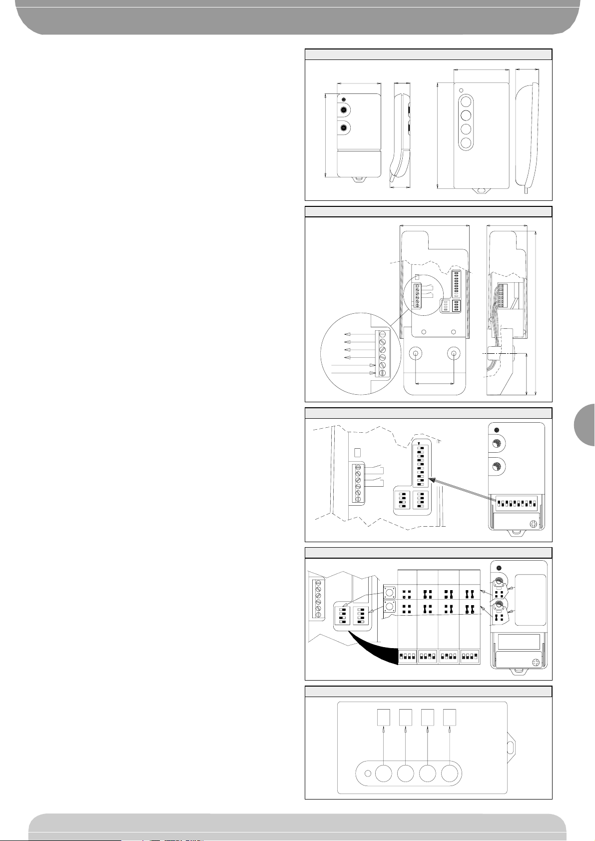
-Dimensions :Look fig.1
-Transmitter versions:TEO1 single-channel with single coding
TEO2 twin channel with single coding.
TEO4 four-channel with single coding.
2) TECHNICAL FEATURES OF THE EXTERNAL RECEIVER
-Reception frequency :433.92Mhz
-Power supply :16 to 28Vac / 11 to 28Vdc
-Antenne : inside
-Relay contact :1A 24Vac-dc
-Working temperature :-20 +55 °C
-Coding by :10 DIP-SWITCH
-Number of combinations :1024 for channel
-Dimensions :Look fig.2
-Receiver versions: REO1 E - single-channel with single coding.
REO2 E - twin-channel with single coding.
3) INSTALLATION
-The presence of metallic objects next to the receiver can disturb the radio
receptor. If the transmitter has insufficient range, move the receiver to a
more suitable position.
4) CONNECTION
Carry out the joint as it is shown in fig.2
5) SETTING OF CODING
The coding of transmission code is set by means of the 10 path DIP
SWITCH which is present in all the transmitters. This coding must coincide
with the one set in the 10 path DIP SWITCH present on the receiver (fig.3).
6) TRANSMISSION TEOx-REOx CHANNEL SELECTION
The 4 path DIP-SWITCH present in the receiver, allows the changing of the
address for activating the transmission channel out of the four available
(fig.4).
The CHx channel address selected with the 4 path DIP SWITCH in the
receiver, must correspond to the one set in the transmitter by means of the
points to be welded (fig.4).
- The transmitter TEO1 normally transmits on the CH1 channel with the
possibility of setting a different address by welding the jumpers present
on the printed circuit (fig.4).
- The transmitter TEO2 normally transmits: button 1-CH1, button 2-CH2,
with the possibility of setting a different address by welding the jumpers
present on the printed circuit (fig.4).
- The transmitter TEO4 normally transmits: button 1-CH1, button 2-CH2,
button 3-CH3, button 4-CH4 without the possibility of setting a different
address (fig.5).
NOTE: The drawings in this manual are purely indicative. The arrangement
of the DIP SWITCH and the POINTS TO BE WELDED may vary. The
procedure described, however, for the SETTING OF THE CODING and
BUTTON - TRANSMISSION CHANNEL ADDRESS remains the same.
FIG. 1
P1
P2
12V
ALKALINE BATTERY
-
+
ON
10987654321
ON
4321
2
S
ON
4311
1
S
ON
4322
1098765
NA
NA
FIJACION CODIFICACION
EINGABE DER CODIERUNG
CODIFICATION
SETTING OF CODING
IMPOSTAZIONE CODIFICA
4
3
2
1
44
18.5
82
TEO4
TEO2
TEO1
16
12.5
65
35
FIG. 2
-
+
24Vac/dc
CH2
CH1
41
162
38.5
4070
NA
NA
FIG. 3
FIG. 4
TEO4
P4
P3
P2
P1
CH4
CH3
CH2
CH1
FIG. 5
ON
4321
3
S
ON
431
1
S
2
P1
P2
P2
P1
12V
ALKALINE BATTERY
-
+
ON
21
43
ON
21
43
ON
2143
ON
21
43
Puntos a soldar
Stellen zu schweksen
Points to be welder
Points a souder
Piazzole a saldare
CH4CH3CH2CH1
 Loading...