


JoyBook S52 System Disassembly Description
Joybook S52 System Disassembly Description
1. Description
Joybook S52 Disassembly can be divided into three main parts. To be more efficient, it is better to get to know more about disassembly process.
You need the following tools:
- Wiha PicoFinish Slotted Screwdriver (Professional Suggestion)
-Crisscross screwdriver, 0×50mm ( 0×50mm)
-Crisscross screwdriver, 1×60mm ( 1×60mm)
-Flat screwdriver( )
-Snipe nose pliers
-Tweezers
-Soft Cushion
-Screws classification box
-Golden type ( )
-Screw Torque Document
zNote
1.Please turn off Joybook and remove battery before disassemble.
2.The screw for different components may very with size.
3.During disassemble process, collect the screws together with correspondent parts for avoid mismatch when assemble.
4.Put a soft pad between repair desk and Joybook to prevent scratch during repair.
5.Void to scrape machine appearance during disassembly.
|
|
|
|
|
Form No JBS52-DOC-004 |
- 1 - |
Confidential □ High ■ Medium □ Low |
||
JoyBook S52 System Disassembly Description
2.System Disassembly
The section discusses at length each major component for disassembly/reassembly and show corresponding illustrations. Use another document “Disassembly Flow Chart” for auxiliary to determine the disassembly sequence for removing components from the notebook.
NOTE: Before you start to install/replace these modules, disconnect all peripheral devices and make sure the notebook is not turned on or connected to AC power.
|
|
|
|
|
1.1.1 Battery Pack |
|
|
|
|
|
1.1.2 HDD Cover/ HDD Module |
|
|
|
|
1.Modular Components |
1.1..3 ODD Module/ ODD Bezel |
|
|
|
|
||
|
|
|
|
1.1.4 DDR-SDRAM |
|
|
|
|
|
|
|
|
|
|
|
|
1.1.5 WLAN Card |
|
|
|
|
|
1.1.6 Keyboard Cover/ Keyboard |
|
|
|
|
Top |
2.1.1 Top Case/Touchpad Case/ Touchpad cable/ MIC cable |
S52 |
|
|
|
2. System Assy |
2.2.1 MB |
|
|||||
|
|
|
|
2.2.2 Thermal/ CPU |
|
|
|
|
|
|
|
|
|
|
|
Base |
2.2.3 CRT PCB board / cable |
|
|
|
|
|
2.2.4 Bluetooth Module |
|
2.2.5 Speakers (L/R) |
|
|
2.2.6 Bottom Case |
|
|
3.1.1 LCD Bezel |
|
3. LCD ASSY |
3.1.2 Hinge Bracket (L/R) |
|
3.1.3 LCD Cover Module |
||
|
|
|
|
|
|
Form No JBS52-DOC-004 |
- 2 - |
Confidential □ High ■ Medium □ Low |
||

JoyBook S52 System Disassembly Description
1. Modular Components
You can easily disassemble “Modular components” (as below indication) no need to disassemble main system.
Battery
ODD |
|
|
RAM |
|
|
|
|
|
K/B Cover |
|
|
|
|
|
|
|
|
|
|
|
|
|
|
|
|
|
|
|
|
|
|
|
|
|
|
|
|
|
|
|
|
K/B |
|
|
|
|
MINI PCI |
|
|
|
|
|
|
|
|
|
|
|
|
|
HDD |
|
|
|
|
|
|
|
|
|
|
|
|
|
||
|
|
|
|
|
|
|
|
|
|
|
|
|
|
|
|
|
|
|
|
|
|
|
|
|
|
|
|
|
|
|
|
|
Port-replicator
Seal Label Position
(Option )
|
|
|
|
|
Form No JBS52-DOC-004 |
- 3 - |
Confidential □ High ■ Medium □ Low |
||
JoyBook S52 System Disassembly Description
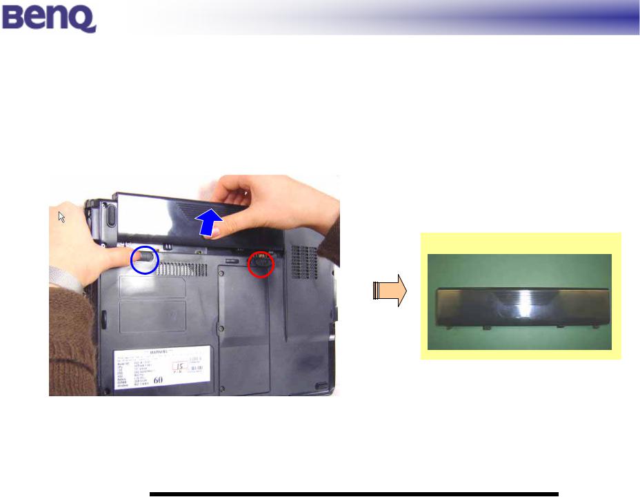
1.1.1 Battery Pack
Disassembly
1. Carefully put the notebook upside down.
2. Pull the battery pack out of the compartment “unlock” ○ position ( n ). (Figure 2-1)
 n
n
while sliding and holding the release lever outwards to the
Battery
Figure 2-1 Remove the battery pack
|
|
|
|
|
Form No JBS52-DOC-004 |
- 4 - |
Confidential □ High ■ Medium □ Low |
||
JoyBook S52 System Disassembly Description
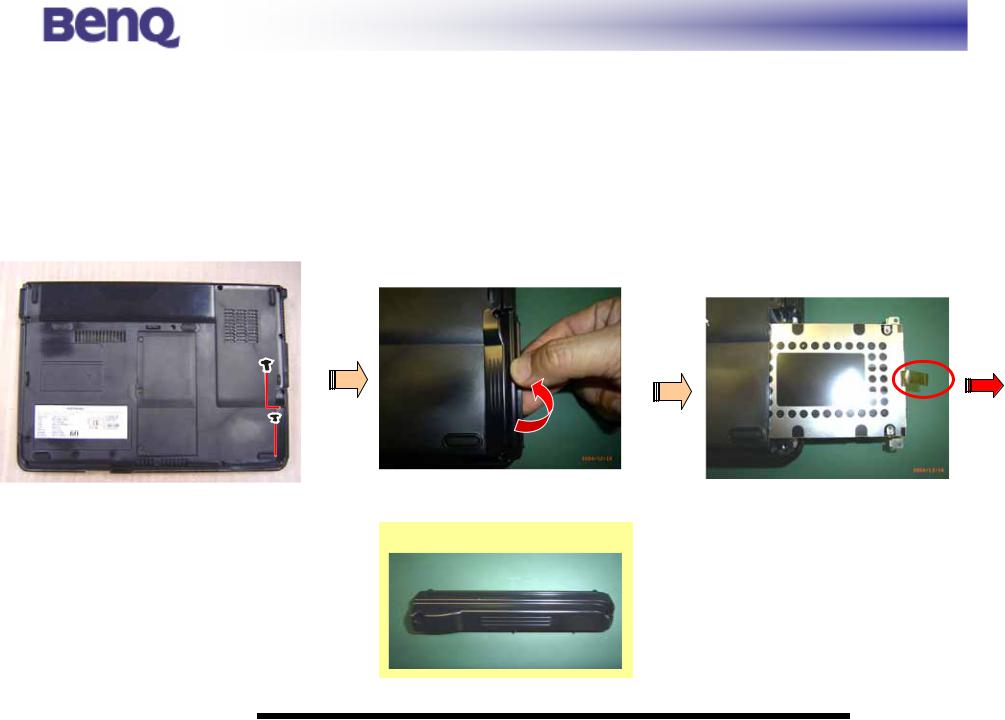
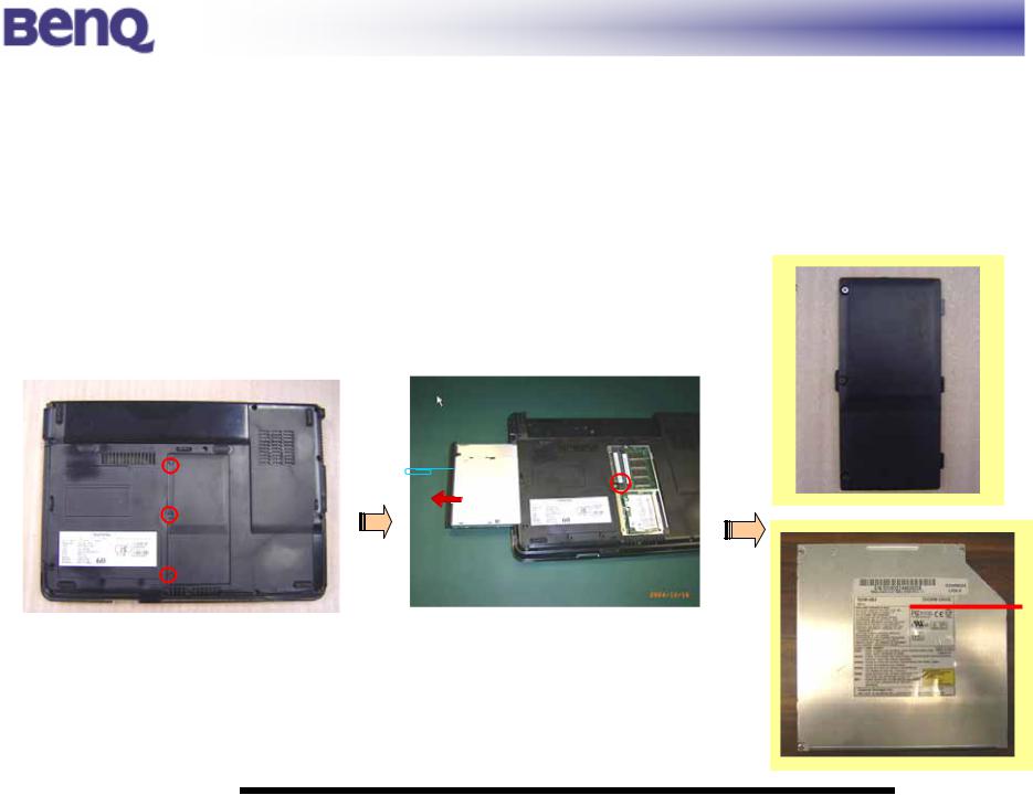
1.1.2HDD Module
Disassembly
1.Carefully put the notebook upside down. And remove the battery pack. (Refer to section 2.2.1 disassembly)
2.Remove 2 *(item 24) screws fastening the HDD compartment cover (Figure 2-2), and lift the HDD cover up. (Figure 2-3).
3.Pull the HDD module right forward from the system.
|
|
|
|
|
|
|
|
|
|
|
|
|
|
|
|
|
|
|
|
|
|
|
|
|
|
|
|
|
|
|
|
|
|
|
|
|
|
|
|
|
|
|
|
|
|
|
|
Figure 2-2 Remove the HDD cover |
Figure 2-3 HDD cover |
Figure 2-4 Pull the HDD drive out |
|||||
|
|
|
|
|
|
|
|
HDD Cover
|
|
|
|
|
Form No JBS52-DOC-004 |
- 5 - |
Confidential □ High ■ Medium □ Low |
||
JoyBook S52 System Disassembly Description
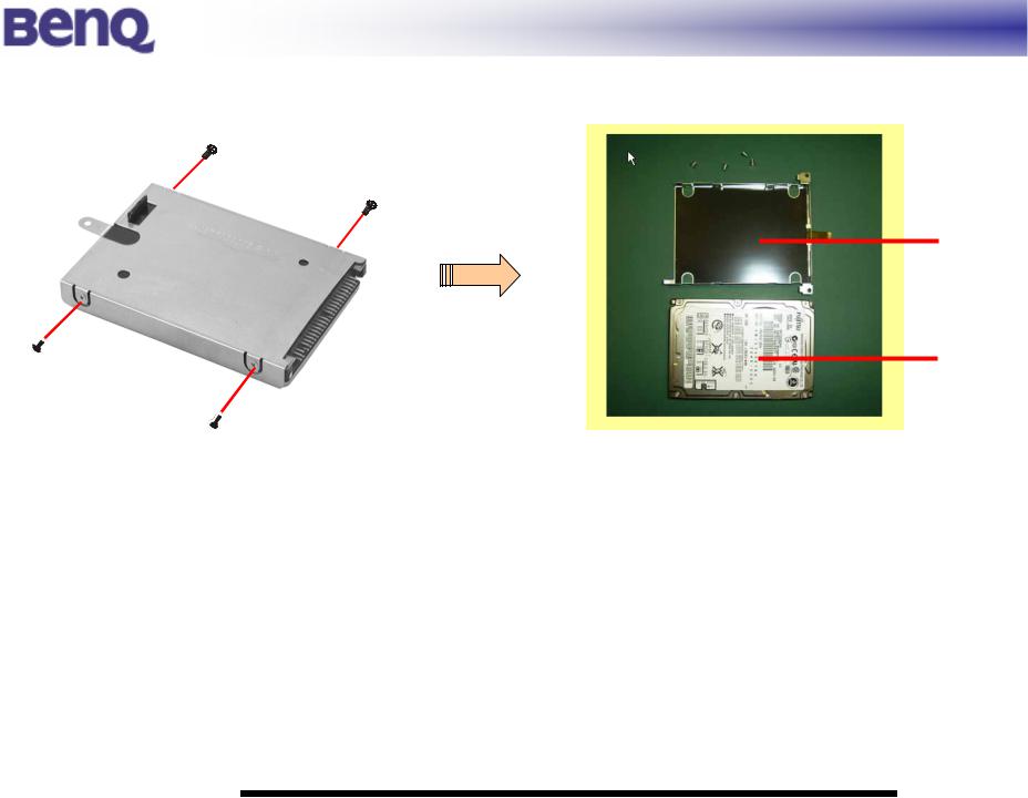
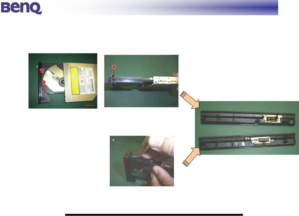
4. Refer to step3, remove 4 *(item 23) screws to separate the HDD module from the HDD case. (Figure 2-4).
HDD case
HDD module
Figure 2-4 Free the HDD drive
|
|
|
|
|
Form No JBS52-DOC-004 |
- 6 - |
Confidential □ High ■ Medium □ Low |
||
JoyBook S52 System Disassembly Description
1.1.3ODD Module (Configuration: DVD & CD-RW Combo/ DVD+RW/ DVD Super-Multi)
Disassembly
1. Carefully put the notebook upside down. And remove the battery pack. (Refer to section 2.1.1 disassembly) 2. Put the notebook back to the upright position. Loosen the 3 screws ( ) to release RAM Door. (Figure 2-5).
3. Then insert a small rod, such as a straightened paper clip, into the drive’s manual eject hole and push firmly to release the tray (o). Pull the tray out until fully extended ( ), then carefully pull harder to remove the ODD Module. (Figure
2-6)
RAM
 Door
Door
n
ODD
Module
Figure 2-5 Remove the ODD Module |
Figure 2-6 Remove the ODD Module |
|
|
|
|
|
Form No JBS52-DOC-004 |
- 7 - |
Confidential □ High ■ Medium □ Low |
||

JoyBook S52 System Disassembly Description
ODD Bezel
There are 2 kinds of bezel includes of GBAS (Quanta) and KME (Panasonic).
How to adjust what kind of your ODD?
KME (Panasonic) |
GBAS (Quanta) |
|||
|
|
|
|
|
|
|
|
|
|
|
|
|
|
|
|
|
|
|
|
|
|
|
|
|
Form No JBS52-DOC-004 |
- 8 - |
Confidential □ High ■ Medium □ Low |
||
JoyBook S52 System Disassembly Description
KME Disassembly
1.Refer to section 2.1.3 (o) step.
2.Remove 3 screws (item 25) as the indication. (Figure 2-7)
Figure 2-7 Remove 3 screws
GBAS Disassembly
1. Turn the ODD to leftside. And push forward the bezel with tweezers lightly as the indication to release it.
(Figure 2-8)
Figure 2-8 push with tweezers
|
|
|
|
|
Form No JBS52-DOC-004 |
- 9 - |
Confidential □ High ■ Medium □ Low |
||
JoyBook S52 System Disassembly Description
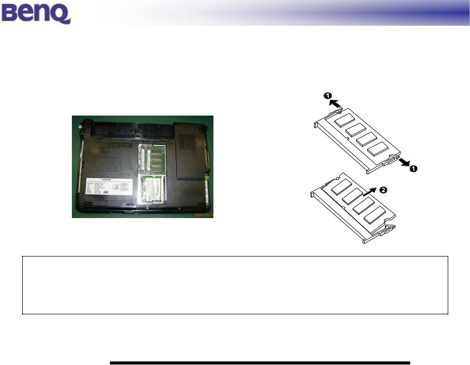
1.1.4DDR-SDRAM
Disassembly
1. |
Refer to section 2.1.3 disassembly ( ) step to remove Door. (Figure 2-9) |
||
2. |
Pull the retaining clips outwards (n) and remove the DDR-SDRAM from the socket (o).(Figure 2-10) |
||
|
|
|
|
|
|
|
|
Figure 2-9 Remove the cover first |
Figure 2-10 Remove the DDR-SDRAM |
Reassembly
To install the DDR, match the DDR's notched part with the socket's projected part and firmly insert the DDR into the socket at 20-degree angle. Then push down until the retaining clips lock the DDR into position.
|
|
|
|
|
Form No JBS52-DOC-004 |
- 10 - |
Confidential □ High ■ Medium □ Low |
||
 Loading...