


PM200M00
BenQ PM200M00, PM245P00, PM250M01, PM300P00, PM318B00 Installation Manual
...
BBeennQQ SSoollaarr PPhhoottoovvoollttaaiicc M
Moodduulleess
IInnssttaallllaattiioonn GGuuiiddee
((IIEECC,, EETTLL))
PM200M00
PM245P00
PM250M01
PM300P00
PM318B00
PM318B01
PM096B00
PM096B01
Version 1.2
Note: The content of this manual is subject to change without notice.
© 2013 AU Optronics All Rights Reserved

2013/10/08 1
BenQ Solar Photovoltaic Modules (IEC, ETL)
Installation Guide for Users
Table of Contents
Chapter 1 General Information .................................................................................................. 2
1.1 Introduction .................................................................................................................. 2
1.2 Limited Warranty and Product Certifications............................................................... 2
1.3 Disclaimer of Liability ................................................................................................. 2
1.4 Guidelines for Safe Handling and Installation ............................................................. 3
Chapter 2 BenQ Solar Module Specifications ........................................................................... 6
2.1 PM200M00 Series........................................................................................................ 6
2.2 PM245P00 Series ......................................................................................................... 6
2.3 PM250M01 Series........................................................................................................ 7
2.4 PM300P00 Series ......................................................................................................... 7
2.5 PM318B00/PM318B01/PM096B00 /PM096B01 Series ............................................. 7
2.6 Performance of PV Modules ........................................................................................ 8
Chapter 3 Mounting Guidelines ................................................................................................. 9
3.1 Mounting with Screws ................................................................................................. 9
3.2 Mounting with Clamps............................................................................................... 10
Chapter 4 Electrical Installation: Wiring and Grounding ........................................................ 12
4.1 Wiring......................................................................................................................... 12
4.2 System Grounding (Negative).................................................................................... 14
4.3 System Grounding (Positive) ..................................................................................... 15
4.4 System Grounding (Transformer less) ....................................................................... 15
4.5 Limitation in Connection ........................................................................................... 15
Chapter 5 Maintenance............................................................................................................. 17
5.1 Module Cleaning Guidelines...................................................................................... 17
5.2 Module Cleaning Instructions .................................................................................... 18
5.3 Cleaning the Frame .................................................................................................... 18
5.4 Visual inspection of the module ................................................................................. 18
5.5 Inspecting connections and cabling............................................................................ 18
Chapter 6 Certifications ........................................................................................................... 20
6.1 IEC Certification ........................................................................................................ 20
6.2 ETL Certification ....................................................................................................... 20

2013/10/08 2
Chapter 1 General Information
1.1 Introduction
The following is the product installation guide for the BenQ Solar photovoltaic modules.
BenQ Solar modules should be installed by certified professionals only. This guide is
designed to be used in combination with industry recognized best practices and all applicable
rules and regulations.
Please read these instructions in entirety before handling or using this product in any way.
IMPORTANT
BenQ Solar modules and this guide are designed for use by certified professionals only.
Failure to follow instructions in this guide AND observe industry best practices may
result in dangerous conditions and could void the product warranty.
1.2 Limited Warranty and Product Certifications
See BenQ Solar Limited Warranty document for full product warranty details and limitations.
Product Warranty version is based on warranty note in effect at the time of product
manufacturing date.
See individual Module Specifications sheet for more information about product certifications
of the desired BenQ Solar module model.
The most up to date version of both of these documents can be found in the BenQsolar.com
Document Center.
http://www.benqsolar.com/?sn=1037&lang=en-US
1.3 Disclaimer of Liability
It is each installer’s responsibility to abide by all relevant rules and regulations when using
this product. Always observe Industry Best Practices when handling, installing, and using this
product. This guide is designed for use by trained and certified solar professionals only. BenQ
Solar does not assume responsibility for loss, damage or expense resulting from installation,
handling or use of this product.

2013/10/08 3
1.4 Guidelines for Safe Handling and Installation
IMPORTANT
THIS PRODUCT IS DESIGNED FOR INSTALLATION BY QUALIFIED
PERSONNEL ONLY.
ALL HANDLING AND INSTALLATIONS MUST BE PERFORMED IN
COMPLIANCE WITH ALL APPLICABLE CODES, RULES AND REGULATIONS.
In addition to the applicable rules and regulations, please follow all guidelines for safe
handling and/or installation of BenQ Solar modules. In addition to the guidelines below,
always observe industry best practices when handling and/or installing any BenQ Solar
module. Save this Installation Guide for future reference.
LIFTING AND HANDLING
Do not lift the module or carry module by junction box or PV cables.
Do not drill holes in the frame.
Avoid scratching the frame. Scratches to the frame will compromise protective coating
and can result in corrosion or weakened structure.
Do not scratch or damage the module backsheet. Scratches to the backsheet could
affect module performance.
Do not stand on, drop, scratch or allow objects to hit modules (especially module glass).
Do not install or handle the modules when wet or during periods of high wind.
Do not install the modules where there may be flammable gases or vapors, since sparks
may be produced.
Save these instructions for future reference.
ELECTRICAL HANDLING AND INSTALLATION
Modules interconnect points conduct direct current (DC) and are sources of voltage
when the module is under load and when it is exposed to light.
Direct current can arc across gaps and may cause injury or death if improper
connection or disconnection is made, or if contact is made with module leads that
are frayed or torn.

2013/10/08 4
Please use caution when handling any module.
Remove all metallic jewelry prior to installing this product to reduce the chance of
accidental exposure to live circuits.
Use properly insulated tools to reduce your risk of electric shock.
Do not touch the terminals while the module is exposed to light.
During installation use suitable protection prevent a discharge of at least 30 direct
current volts to each person on crew.
Do not connect or disconnect modules when current from the modules or an external
source is present.
Do not remove or misuse module connectors, this could void module warranty.
Cover all modules in the PV array with an opaque material before making or breaking
any connections.
Use only the supplied locking connectors and safety clips in order to prevent untrained
persons from disconnecting the modules once installed.
There are no serviceable parts within the module. Do not attempt to change or repair any
part of the module.
Damaged modules (broken glass, torn back sheet, broken j-boxes, broken connectors, etc)
can present electrical hazards as well as laceration hazards. Contact with damaged
module surfaces or module frame can cause electric shock. The dealer or installers
should remove the module from array and contact the supplier for disposal instructions.
STORAGE
When storing modules for any period of time, cover modules to ensure protection from
the elements.
When storing the modules, turn so that the glass is face down. Do not allow water to
collect inside module, this can damage module connectors.
When storing the modules, do not allow the anodized profiles (frames) to come into
contact with contaminants such as cement or mortar, which will cause damage to the
anodic oxide coatings.
*Always contact your module supplier for additional instructions if maintenance is

2013/10/08 5
necessary.*
2013/10/08 6
Chapter 2 BenQ Solar Module Specifications
The module electrical ratings are measured under Standard Test Conditions (STC) of
1000W/m2 irradiance with AM 1.5G spectrum and a cell temperature of 25ºC. BenQ Solar
modules electrical characteristics depend on module Series and Wattage. Please refer to the
tables below to learn more about the characteristics of your module(s).
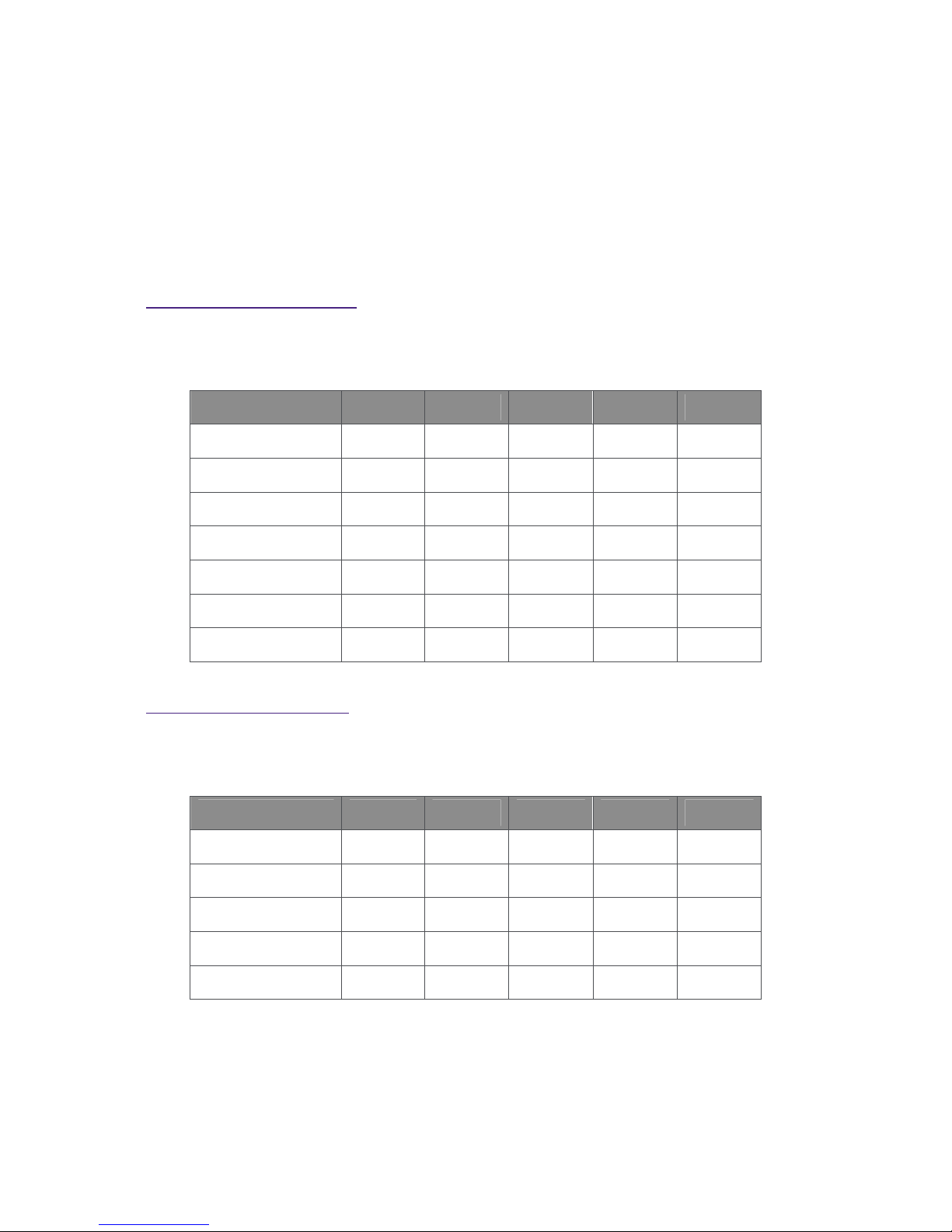
2.1 PM200M00 Series
Module Dimensions (L x W x H): 1318 x 983 x 40 mm (51.87 x 38.70 x 1.57 in)
Module Weight: 15.4 kg (33.5 lbs)
Module Type Pmax (W) Voc (V) Isc (A) Vmp (V) Imp (A)
PM200M00_190 190 30.2 8.60 23.6 8.06
PM200M00_195 195 30.3 8.68 23.7 8.23
PM200M00_200 200 30.4 8.76 23.9 8.37
PM200M00_205 205 30.5 8.84 24.1 8.51
PM200M00_210 210 30.6 8.92 24.3 8.65
PM200M00_215 215 30.7 9.00 24.4 8.82
PM200M00_220 220 30.8 9.08 24.5 8.99
2.2 PM245P00 Series
Module Dimensions (L x W x H): 1639 x 983 x 40 mm (64.52 x 38.7 x 1.57 in)
Module Weight: 18.5 kg (41.1 lbs)
Module Type Pmax (W) Voc (V) Isc (A) Vmp (V) Imp (A)
PM245P00_240 240 37.0 8.58 29.9 8.03
PM245P00_245 245 37.2 8.64 30.3 8.09
PM245P00_250 250 37.4 8.69 30.6 8.17
PM245P00_255 255 37.6 8.76 30.8 8.28
PM245P00_260 260 37.7 8.83 31.2 8.34
 Loading...