

Page 1
L8542878
Rev. 09/09/00
AUTOMAZIONE A TRAINO PER PORTE SEZIONALI RESIDENZIALI
PULLING AUTOMATIC SYSTEM FOR RESIDENTIAL SECTIONAL DOORS
AUTOMATISCHE SCHLEPPVORRICHTUNG FÜR SEKTIONALE TÜREN
AUTOMATISME À ENTRAÎNEMENT POUR PORTES SECTIONNELLES RESIDENTIALES
AUTOMATIZACIÓN DE ARRASTRE PARA PUERTAS SECCIONALES RESIDENTIALES
POCIĄGNIK AUTOMATYCZNY DO BRAM SEKCYJNYCH
JM.3PRO
Libro istruzioni e catalogo ricambi
Operating instructions and spare parts catalogue
Betriebsanleitung und Ersatzteilliste
Livret d’instructions et catalogue des pieces de rechange
Maual de instrucciones y catálogo de recambios
Książeczka z instrukcjami i katalog części wymiennych
UNIONE NAZIONALE COSTRUTTORI
AUTOMATISMI PER CANCELLI, PORTE,
SERRANDE ED AFFINI
Page 2

3
Dichiarazione CE di conformità per macchine
(Direttiva 89/392 CE, Allegato II, parte B)
Divieto di messa in servizio
Fabbricante: Automatismi Benincà SpA.
Indirizzo: Via Capitello, 45 - 36066 Sandrigo (VI) - Italia
Dichiara che: l’automazione a traino per porte sezionali modello JM.3PRO
• è costruito per essere incorporato in una macchina o per essere assemblato con altri macchinari per costituire una macchina
considerata dalla Direttiva 89/392 CE, come modicata;
• non è dunque conforme in tutti i punti alle disposizioni di questa Direttiva;
• è conforme alle condizioni delle seguenti altre Direttive CE:
Direttiva bassa tensione 73/23/CEE, 93/68/CEE.
Direttiva compatibilità elettromagnetica 89/336/CEE, 93/68/CEE.
e che:
• sono state applicate le seguenti (parti/clausole di) norme armonizzate:
EN 55022, EN 61000-3-2, EN 61000-3-3, EN 50082-1, EN 60335-1.
e inoltre dichiara che non è consentito mettere in servizio il macchinario no a che la macchina in cui sarà incorporato o di cui diverrà
componente sia stata identicata e ne sia stata dichiarata la conformità alle condizioni della Direttiva 89/392 CE e alla legislazione
nazionale che la traspone, vale a dire no a che il macchinario di cui alla presente dichiarazione non formi un complesso unico con
la macchina nale.
Benincà Luigi, Responsabile legale.
Sandrigo, 10/02/2007.
Declaration by the manufacturer
(Directive 89/392/EEC, Art. 4.2 and Annex II, sub B)
Divieto di messa in servizio
Manufacturer: Automatismi Benincà SpA.
Address: Via Capitello, 45 - 36066 Sandrigo (VI) - Italia
Herewith declares that: the pulling automatic system for sectional doors model JM.3PRO
• is intended to be incorpored into machinery or to be assembled with other machinery to constitute machinery covered by Directive
89/392 EEC, as amended;
• does therefore not in every respect comply with the provisions of this Directive;
• does comply with the provisions of the following other EEC Directives:
Direttiva bassa tensione 73/23/CEE, 93/68/CEE.
Direttiva compatibilità elettromagnetica 89/336/CEE, 93/68/CEE.
and that:
• the following (parts/clauses of) harmonized standards have been applied:
EN 55022, EN 61000-3-2, EN 61000-3-3, EN 50082-1, EN 60335-1.
and furthermore declares that it is not allowed to put the machinery into service until the machinery into which it is to be incorporated
or of which it is to be a component has been found and declared to be in conformity with the provisions of Directive 89/392/EEC and
with national implementing legislation, i.e. as a whole, including the machinery referred to in this declaration.
Benincà Luigi, Responsabile legale.
Sandrigo, 10/02/2007.
2
Page 3

Herstellerklärung
(gemäß EG-Richtlinie 89/392/EWG, Artikel 4.2 und Anhang II, sub B.)
Verbot der Inbetriebnahme
Hersteller: Automatismi Benincà SpA.
Adresse: Via Capitello, 45 - 36066 Sandrigo (VI) - Italia
erklärt hiermit, daß: Automatische Schleppvorrichtung für sektionale Türen JM.3PRO
• vorgesehen ist zum Einbau in eine Maschine oder mit anderen Maschinen zu einer Maschine im Sinne der Richtlinie 89/392/
EWG, inklusive deren Änderunge, zusammengefügt werden soll;
• aus diesem Grunde nicht in allen Teilen den Bestimmungen dieser Richtlinie entspricht;
• den Bestimmungen der folgenden anderen EG-Richtlinien entspricht:
Direttiva bassa tensione 73/23/CEE, 93/68/CEE.
Direttiva compatibilità elettromagnetica 89/336/CEE, 93/68/CEE.
und daß:
• folgende harmonisierte Normen (oder Teile/Klauseln hieraus) zur Anwendung gelangten:
EN 55022, EN 61000-3-2, EN 61000-3-3, EN 50082-1, EN 60335-1.
und erklärt des weiteren daß die Inbetriebnahme solange untersagt ist, bis die Maschine oder Anlage, in welche diese Maschine
eingebaut wird oder von welcher sie eine Komponente dasteilt, als Ganzes (d.h. inklusive der Maschine, für welche diese Erklärung
ausgesteilt wurde) den Bestimmungen der Richtlinie 89/392/EWG sowie dem entsprechenden nationalen Reschtserlaß zur Umsetzung
der Richtlinie in nationales Recht entspricht, und die entsprechende Konformitätserklärung ausgestellt ist.
Benincà Luigi, Responsabile legale.
Sandrigo, 10/02/2007.
Declaration du fabricant
(Directive 89/392/CEE, Article 4.2 et Annex II, Chapitre B)
Interdiction de mise en service
Fabricant: Automatismi Benincà SpA.
Adresse: Via Capitello, 45 - 36066 Sandrigo (VI) - Italia
Déclaire ci-apres que: l’automatisme à entraînement pour portes sectionnelles JM.3PRO
• est prévue pour être incorporée dans une machine ou être assemblée avec d’autres machines pour consituer une machine couverte
par la directive 89/392/CEE, modiée;
• n’est donc pas conforme en tout point aux dispositions de cette directive;
• est conforme aux dispositions des directives CEE suivantes:
Direttiva bassa tensione 73/23/CEE, 93/68/CEE.
Direttiva compatibilità elettromagnetica 89/336/CEE, 93/68/CEE.
et que:
• les (parties/paragraphes) suivants des normes harmonisées ont été appliquées:
EN 55022, EN 61000-3-2, EN 61000-3-3, EN 50082-1, EN 60335-1.
et déclare par ailleurs qu’il est interdit de mettre la machine en service avant que la machine dans laquelle elle sera incorporée ou
dont elle constitue une parte ait été considerée et declarée conforme aux dispositions de la Directive 89/392/CEE et aux législations
nationales la transposant, c’est-à-dire formant un ensemble incluant la machine concernée par la présente déclaration.
Benincà Luigi, Responsabile legale.
Sandrigo, 10/02/2007.
3
Page 4

5
Declaración CE de conformidad para maquinas
(Directiva 89/392 CE, Apartado II, parte B)
Prohibición de puesta en servicio
Fabricante: Automatismi Benincà SpA.
Dirección: Via Capitello, 45 - 36066 Sandrigo (VI) - Italy
Declara que: la automatización de arrastre para puertas plegables JM.3PRO
• está construída para ser incorporada en una máquina o para ser ensamblada con otras maquinarias para construir una máquina
considerada por la Directiva 89/392 CE, como modicada;
• no es, por consiguiente, conforme en todos los puntos a la posiciones de esta Directiva;
• es conforme a las condiciones de las siguientes otras Directivas CE:
Directiva de la baja tensión 73/23/CEE, 93/68/CEE.
Directiva de compatibilidad electromagnética 89/336/CEE, 93/68/CEE
y que
• han sido aplicadas las siguientes (partes/claúsulas de) normas armonizadas:
EN 55022, EN 61000-3-2, EN 61000-3-3, EN 50082-1, EN 60335-1.
además declara que no ha permitido poner en servicio la maquinaria hasta que la máquina en la cual será incorporada o de la cual
resultará componente esté identicada y no sea declarada la conformidad a las condiciones de la Directiva 89/392 CE y a la legislación
nacional que le corresponda, vale decir, hasta que la maquinaria correspondiente a la presente declaración no forme un conjunto único
con la máquina nal.
Benincà Luigi, Responsable legal.
Sandrigo, 10/02/2007.
Deklaracja UE o zgodności z normami dla maszyn
(Wytyczna 89/392 UE, Załącznik II, Część B)
Zakaz użytkowania
Producent: Automatismi Benincà SpA.
Adres: Via Capitello, 45 - 36066 Sandrigo (VI) - Italia
Oświadcza że: Automatyzm do bram sekcyjnych model JM.3PRO
• został opracowany z myślą o wbudowaniu go do maszyny lub zmontowania z innymi urządzeniami w celu skonstruowania maszyny
uznanej przez Wytyczną 89/392 UE, za zmodykowaną;
• nie jest więc zgodny we wszystkich punktach z Wytyczną;
• jest natomiast zgodny z wymogami innych, poniżej wyszczególnionych, Wytycznych UE:
Wytyczna o niskim napięciu 73/23/EWG i 93/68/EWG
Wytyczna o zdolności współdziałania elektromagnetycznego 89/336/EWG, 93/68/EWG.
i że:
• zastosowane zostały następujące normy (ich klauzule/części) standard:
EN 55022, EN 61000-3-2, EN 61000-3-3, EN 50082-1, EN 60335-1.
ponadto oświadcza, że zabronione jest stosowanie automatyzmu do czasu kiedy maszyna, do której ma być wbudowany lub stanowić
jej element składowy, nie uzyska świadectwa identykacyjnego oraz świadectwa orzekającego jej zgodność z wymogami Wytycznej
89/392 UE oraz z przepisami obowiązującymi w kraju sprowadzającym urządzenie, a więc do czasu kiedy automatyzm stanowiący
przedmiot niniejszego oświadczenia nie stanie się częścią składową urządzenia gotowego.
Benincà Luigi, Radca prawny
Sandrigo 10/02/2007.
4
Page 5
La porta deve aprirsi e chiudersi tirando e spingendo orizzontalmente sul bordo superiore.
It has to be possible to open and close the door by pulling and
pushing horizontally its top edge.
Das Tor muß zu öffnen und zu schließen sein, indem man es an
seinem Oberrand zieht und schiebt.
La porte devra pouvoir être ouverte et fermée en tirant et en
poussant horizontalement sur son bord supérieur.
La puerta debe abrirse y cerrarse tirando y empujando horizontalmente sobre el borde superior.
Brama musi się otwierać i zamykać poprzez poziome
pociąganie i popychanie górnej krawędzi.
min. 40mm
Fig.1
Dati tecnici Technical data Technische Daten
Alimentazione
Alimentazione motore
Potenza assorbita
Velocità di trazione
Forza trazione/spinta
Grado di protezione
Intermittenza lavoro
Temp. funzionamento
Rumorosità
Altezza max. porta:
con PTC3/PTC4
con PTCL4
Peso gruppo motore
Peso totale:
con PTC3/PTC4
con PTCL4
Donnees technique
Alimentation
Alimentation moteur
Puissance absorbée
Vitesse de traction
Force traction/poussée
Indice de protection
Intermittence travail
Temp. fonctionnement
Bruit
Hauteur max. porte:
avec PTC3/PTC4
avec PTCL4
Poids groupe moteur
Poids totale:
avec PTC3/PTC4
avec PTCL4
Feed
Motor feed
Absorbed rating
Drive speed
Drive/thrust force
Degree of protection
Jogging
Operating temp.
Noise level
Max. door height:
with PTC3/PTC4
with PTCL4
Power unit weight
Total weight:
with PTC3/PTC4
with PTCL4
Datos técnicos
Alimentación
Alimentación del motor
Potencia absorbida
Velocidad de tracción
Fuerza tracción/empuje
Grado de protección
Intermitencia de trabajo
Temp. de funcionamiento
Ruido
Altura máx. de puerta:
con PTC3/PTC4
con PTCL4
Peso grupo motor
Peso total:
con PTC3/PTC4
con PTCL4
Speisung
Motorspeisung
Leistung
Zuggeschwindigkeit
Zugkraft/Schubkraft
Schutzart
Betriebsintervall
Betriebstemperatur
Geräuschentwicklung
Max. Torhöhe:
mit PTC3/PTC4
mit PTCL4
Gewicht der Motoreinheit
Gesamtgewicht:
mit PTC3/PTC4
mit PTCL4
Dane techniczne
Zasilanie
Zasilanie silnika
Natężemie
Prędkość ciągnięcia
Siła ciągnięcia/pchania
Stopień ochrony
Cykliczność pracy
Temp. podczas pracy
Max. halas
Wysokość max bramy:
z PTC3/PTC4
z PTCL4
Ciężar zepołu silniko-wego
Ciężar całkowity:
z PTC3/PTC4
z PTCL4
JM.3PRO
230Vac
24Vdc
140W
5,4/8/10 m/1'
600N
IP40
*
-20°C/+70°C
<70dB (A)
2,5m
3,5m
5,9 kg
11,5kg
13,3kg
JM.3PRO
230Vac
24Vdc
140W
3,5/6/8 m/1'
600N
IP40
*
-20°C/+70°C
<70dB (A)
2,5m
3,5m
5,9 kg
11,5kg
13,3kg
* Uso intensivo - Intensive use - Intensive Nutzung - Usage intensif - Uso intensivo - Użytkowanie intensywne
5
Page 6
7
34
202
446
PTC3 3024 / PTC4 3024
PTCL4 4024
PTC3 2660 / PTC4 2660
PTCL4 3660
Fig. 2
Fig. 3
6
Page 7
R
6x18x2 UNI 6593
D
M6 UNI 7474
PTC.3
4+4 M6x16
P
P
Fig. 4a
R
6x18x2 UNI 6593
D
M6 UNI 7474
PTC.4
2+2 M6x16
R2
F
2+2 M6x16
F
PTCL.4
Fig. 4b
7
Page 8
9
Fig. 5
D
Fig. 6
4,8x38
S
P
Fig.7
8
Page 9
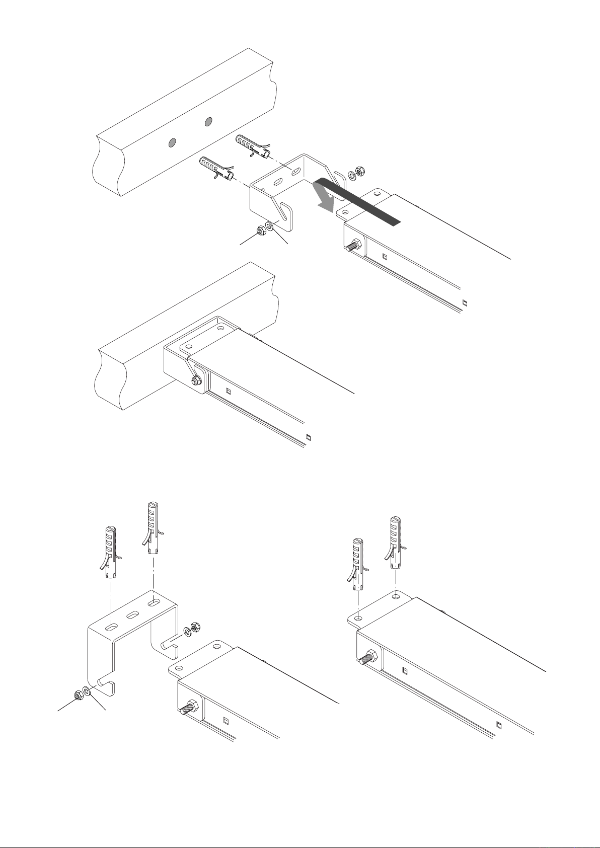
Fissaggio a muro.
Wall xing.
Befestigung an der Mauer.
Fixation murale.
Fijación a la pared.
Przyczepianie do ściany.
M
R
Fig. 8
M
R
Fig. 9
Fissaggio a softto.
Fixing to ceiling.
Befestigung an der Decke.
Fixation au plafond.
Fijación al techo.
Przyczepianie do sutu.
Fissaggio in aderenza al softto
Fixing to ceiling.
Deckenbefestigung
Fixation en adhérence au plafond.
Fijación pegada al techo.
Zamocowanie do sutu
Fig. 10
9
Page 10
11
Fig. 11
PTC.4 / PTCL.4
AU.C25
Fig. 12
10
Page 11
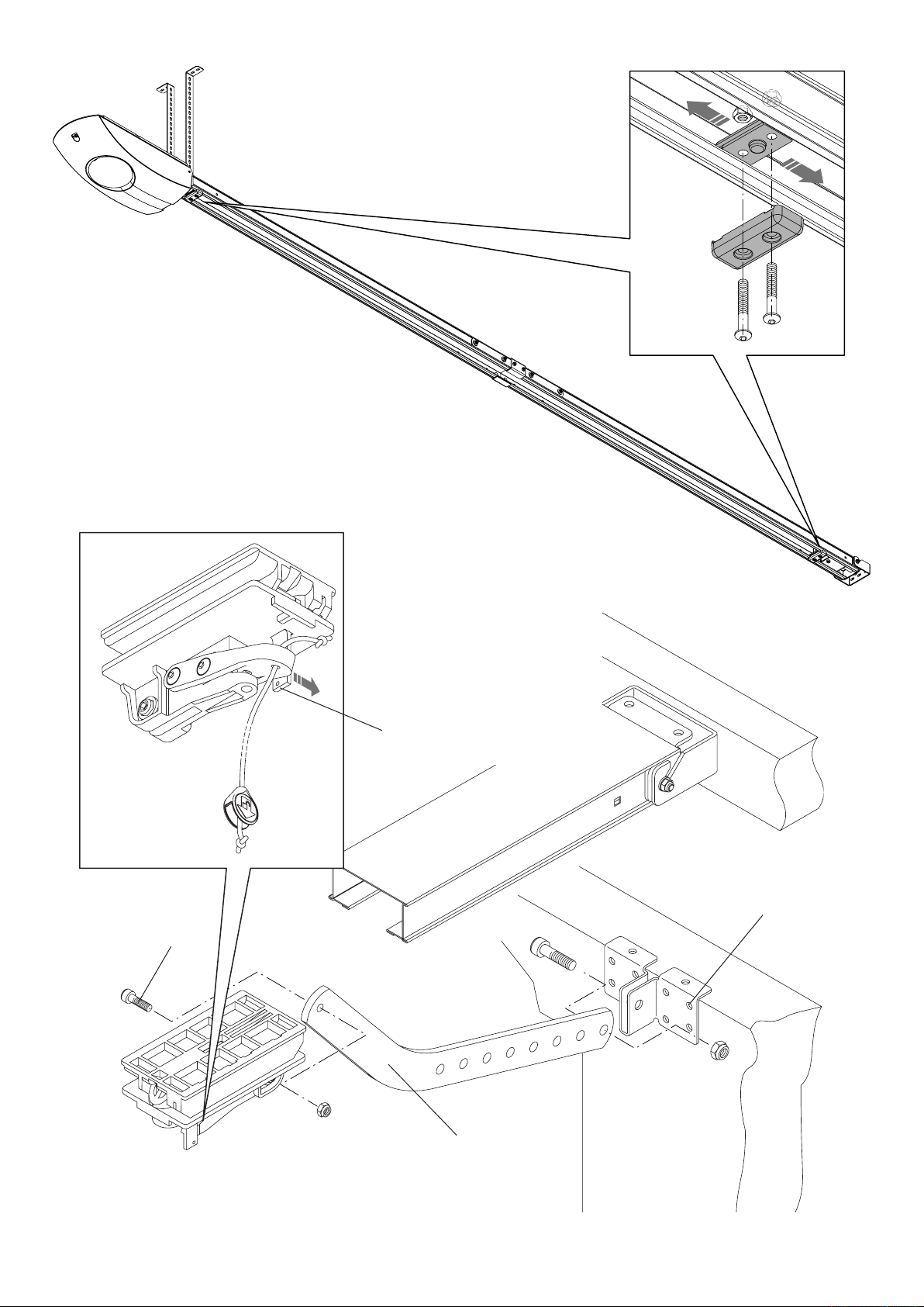
Fig. 13
Per ripristinare il funzionamento automatico
tirare la leva
To reset the automatic operation of the
system pull the lever.
Um die automatische Funktion wieder
herzustellen, den Hebel ziehen.
Pour remettre en état le fonctionnement
automatique tirer le levier.
Para restablecer el funcionamiento automático tirar de la palanca.
W celu przywrócenia działania
automatycznego należy pociągnąć za
dźwignię.
M6X20
S
A
Fig. 14
11
Page 12

13
F1
F2
F1
F2
F1
F2
Fig. 16
Fig. 15
Fig. 17
Fig. 18
12
Page 13

Rosetta 9x24 UNI 6593.
Washer 9x24 UNI 6593.
Scheibe 9x24 UNI 6593.
Rondelle 9x24 UNI 6593.
Arandela 9x24 UNI 6593.
Podkładka 9x24 UNI 6593.
Guaina.
Sheath.
Hülse.
Gaine.
Guaina.
Osłona.
Cavo di acciaio.
Steel cable.
Stahlkabel.
Corde en acier.
Cable de acero.
Pręt żelazny.
Registro.
Register.
Regulierung.
Réglage.
Reglaje.
Rejestr.
Blocca.
Block.
Sperrung.
Blocage.
Bloquea.
Blokuje.
Morsetto.
Clamp.
Klammer.
Étau.
Perrillo.
Zacisk.
Staffa.
Support.
Stütze.
Support.
Soporte.
Zaczep.
Maniglia con piastra.
Handle with plate.
Handgriff mit Platte.
Manette avec plaque.
Manilla con placa.
Uchwyt z płytą.
Rosetta per M8 DIN 6798E.
Washer M8 DIN 6798E.
Scheibe M8 DIN 6798E.
Rondelle M8 DIN 6798E.
Arandela para M8 DIN 6798E.
Podkładka dla M8 DIN 6798E.
Vite M8x10 UNI 5739.
Screw M8x10 UNI 5739.
Schraube M8x10 UNI 5739.
Vis M8x10 UNI 5739.
Tornillo M8x10 UNI 5739.
Śruba M8x10 UNI 5739.
Sblocca.
Unblock.
Freigabe.
Déblocage.
Desbloquea.
Odblokowuje.
Fig.19
13
Page 14

15
Fissare il braccio sul lo superiore della porta.
Fix the arm to the top edge of the door.
Arm an der oberen Kante des Tores befestigen
Fixer le bras sur l’arête supérieure de la porte.
Fijar el brazo en la arista superior de la puerta.
Przymocować ramię do górnego prętu bramy.
Rotaia.
Rail.
Schiene.
Morceau de rail.
Guía.
Szyna.
Braccio per porte a contrappesi art. AU.C25.
Overhead doors with balanceweights: special arm art. AU.C25.
Kipptor mit Gegengewichten: Sonderarm, Teil AU.C25.
Portes basculantes à contrepoids: bras spécial art. AU.C25.
Brazo para puerta de contrapesos art. AU.C25.
Ramię dla bram z przeciwwagą art. AU.C25.
A porta chiusa lasciare 2 ÷ 3 cm.
Keep a distance of 2 ÷ 3 cm when the door is closed.
Wenn die Tür geschlossen ist, lassen 2 ÷ 3 cm.
Il faut lasser 2 ÷ 3 cm quand la porte est ouvert.
Cuando la puerta ésta cerrada, hay que haber 2 ÷ 3 cm.
Podczas zamkniętej bramy pozostawić 2 ÷ 3 cm.
Pattino.
Sliding plate.
Platte.
Plaque.
Patín.
Ślizgacz.
Regolare
Adjust
Regulieren
Régler
Regulación
Regulowanie.
Vite M6x35 UNI 5931
Screw M6x35 UNI 5931
Schraube M6x35 UNI 5931
Vis M6x35 UNI 5931
Tornillo M6x35 UNI 5931
Śruba M6x35 UNI 5931.
Mettere a piombo il braccio.
Level the arm.
Arm lotrecht stellen.
Mettre à plomb le bras.
Aplomar bien el brazo.
Ustawić ramię w pozycji
pionowej.
Fig.20
14
Page 15

Introduzione
Ci congratuliamo con Voi per aver scelto il motoriduttore JM.3PRO.
Tutti gli articoli della vasta gamma Benincà sono il frutto di una ventennale esperienza nel settore degli automatismi e
di una continua ricerca di nuovi materiali e di tecnologie all’avanguardia.
Proprio per questo, oggi siamo in grado di offrire dei prodotti estremamente afdabili che, grazie alla loro potenza, efcacia e durata, soddisfano pienamente le esigenze dell’utente nale.
Tutti i nostri prodotti sono coperti da garanzia.
Inoltre, una polizza R. C. prodotti stipulata con primaria compagnia assicurativa copre eventuali danni a cose o persone
causati da difetti di fabbricazione.
1. Notizie generali
L’automatismo è concepito per motorizzare porte sezionali; per essere applicato su porte basculanti necessita di uno
speciale braccio di attacco (art. AU.C25).
In ogni caso dovranno essere assolte le seguenti condizioni:
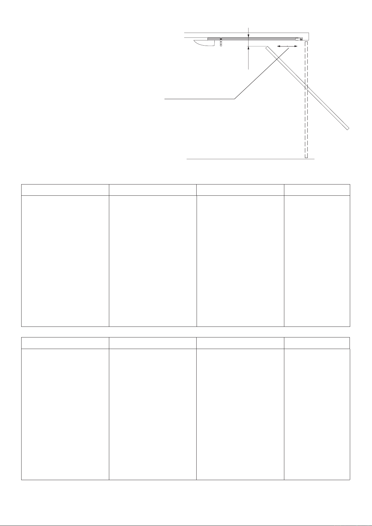
- la distanza tra il punto più alto della porta ed il softto deve essere almeno 40mm (g.1);
- la porta deve potersi aprire e chiudere tirando e spingendo orizzontalmente sul suo bordo superiore (g.1);
- le manovre manuali devono risultare dolci e regolari.
2. Installazione
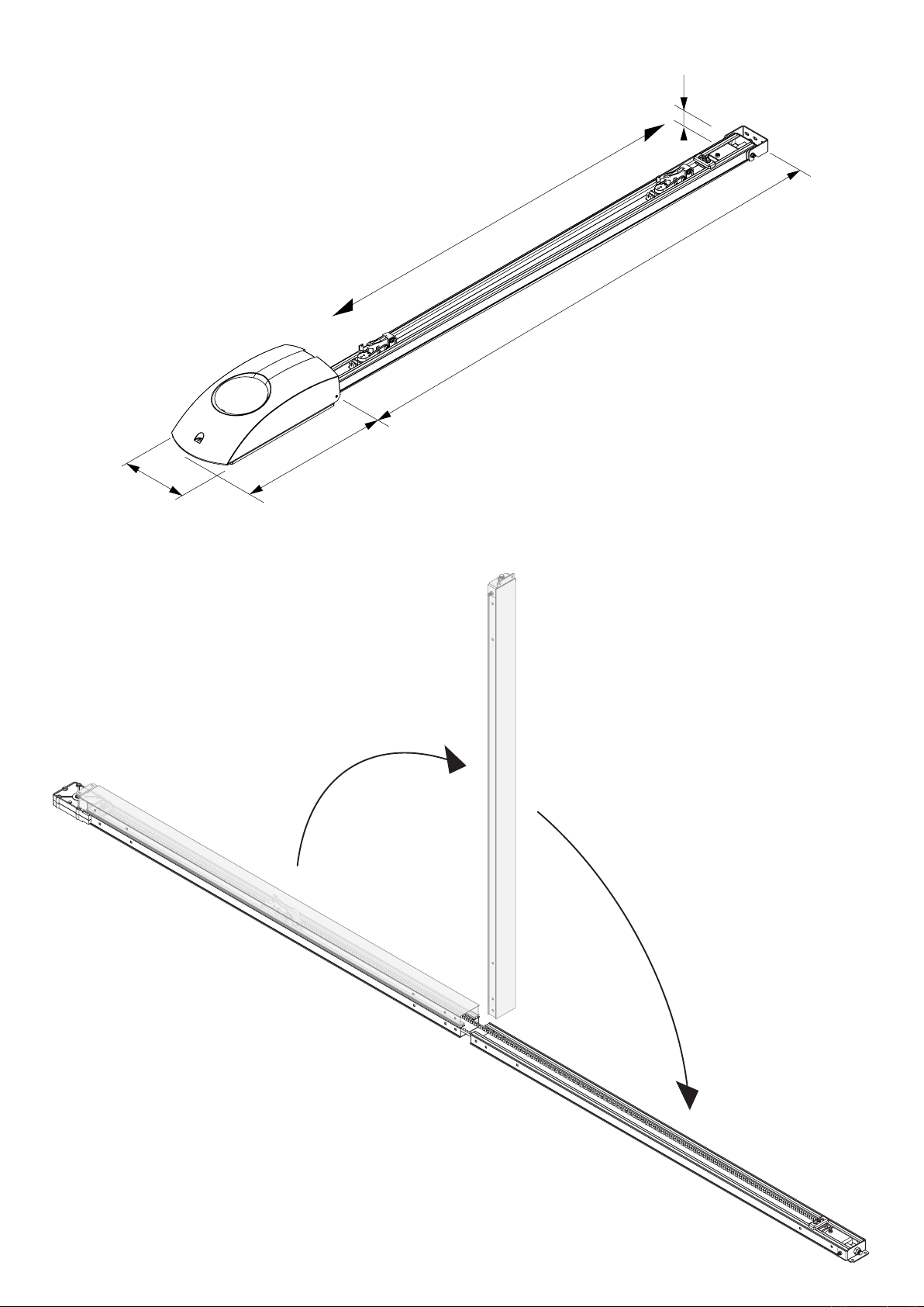
a) posare la rotaia su una supercie piana e distenderla come indicato in Fig.3
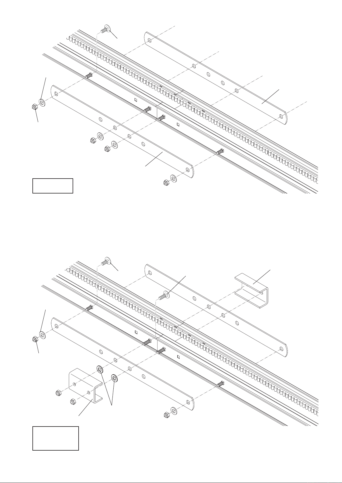
b) facendo riferimento a Fig. 4a, allineare le due estremità delle rotaie e ssarle con i due piatti P utilizzando le 8 viti
M6X16, i dadi D e le rondelle R.
Nel caso di utilizzo della rotaia PTC4/PTCL.4 occorre ssare anche le staffe F evidenziate in Fig.4b, facendo attenzione
alla posizione delle rondelle R2 che devono essere interposte tra staffa F e piatto P.
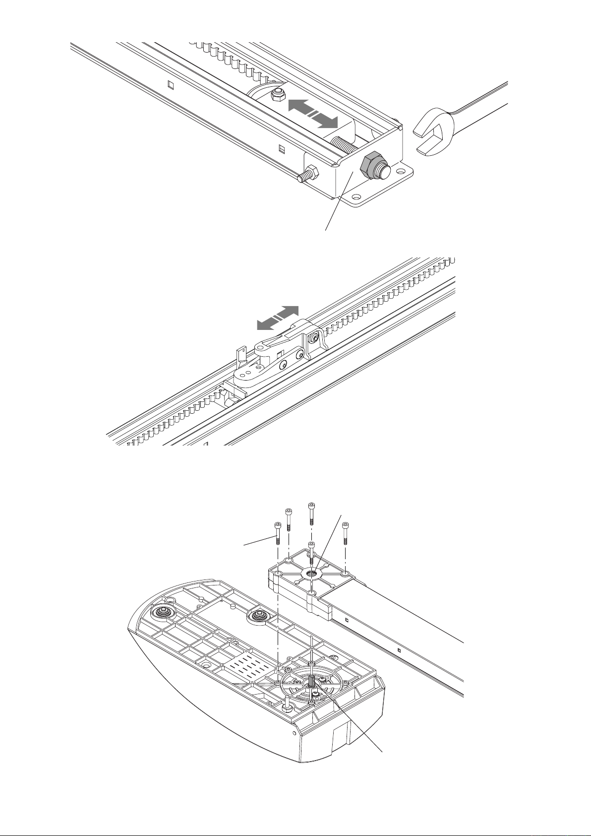
c) vericare il tensionamento della cinghia, se necessario può essere regolata a mezzo del dado D evidenziato in
Fig.5.
La cinghia correttamente tensionata mantiene la posizione lungo tutto il binario, senza essioni, risultando in ogni caso
cedevole ad una leggera pressione manuale.
d) muovere il carrello di trascinamento (Fig.6) no a far collimare la sede della puleggia (rif. S di Fig. 7) con il perno del-
l'albero motore (rif. P di Fig. 7)
e) ssare il binario alla base del motoriduttore come da Fig.7. Fissare con le 5 viti D4,8x38 la rotaia alla base del
motoriduttore.
f) ssare la staffa di aggancio S al muro (Fig.8) o al softto (Fig.9), tracciando in corrispondenza al centro della porta i due
punti di ssaggio. Agganciare la rotaia alla staffa e ssarla con i dadi M e le rondelle R. Posare il corpo motoriduttore
a terra.
Se gli spazi non consentono l'uso della staffa S, è possibile ssare il binario direttamente al softto utilizzando i fori
evidenziati in Fig.10.
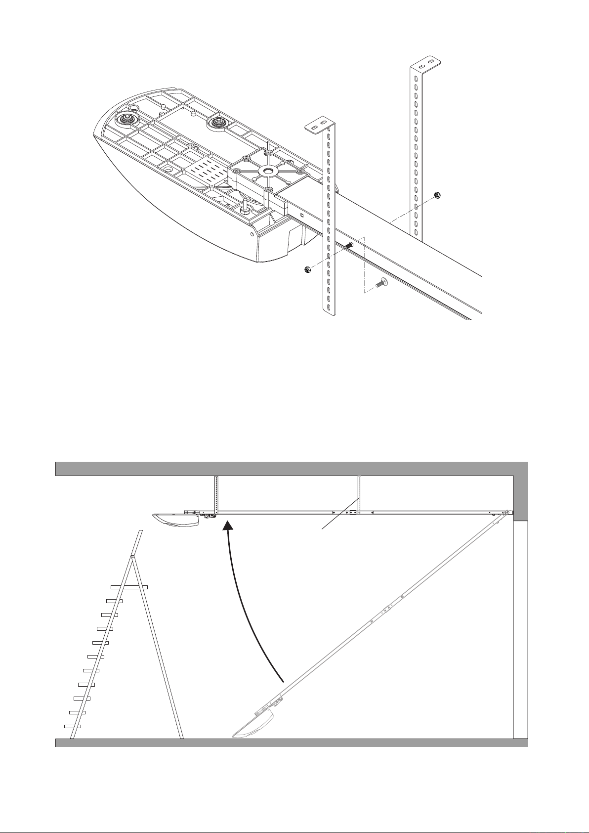
g) predisporre le staffe di attacco al softto utilizzando le apposite sedi nella rotaia in prossimità del motoriduttore (Fig.11)
e ssandole con le viti M i dadi D. Nelle rotaie PTC.4 e PTC.L4 sono fornite altre due staffe di attacco al softto da
ssare in prossimità della giunzione tra i binari.
h) utilizzando una scala alzare il motoriduttore (Fig.12), segnare i punti di ssaggio delle staffe, forare e ssare il
motoriduttore utilizzando viti e tasselli adatti al materiale.
i) ssare i fermi meccanici di apertura e chiusura, a inizio e ne binario, come evidenziato in Fig.13. I fermi verranno
successivamente posizionati con maggior precisione durante la fase di messa a punto dell'automazione
l) collegare l’asta di trascinamento A al pattino di trascinamento mediante la vite a testa cilindrica M6x20 e il dado au-
tobloccante, evitando di bloccare l’asta stessa. Fissare la staffa S alla porta in modo che, a porta chiusa, l’asta A sia
in posizione pressoché verticale. Se necessario accorciare l'asta di trascinamento A.
Nel caso di ante pesanti si consiglia di utilizzare sia i fori superiori sia quelli frontali.
m) Inlare il cordino nella leva si blocco e nel pomello e annodare come indicato nel particolare di Fig.14
n) applicare alla porta l'adesivo di avvertenza fornito in dotazione:
3. Memorizzazione delle posizioni di apertura e chiusura
Il motoriduttore dispone di una centrale di comando con funzione di memorizzazione delle posizioni di apertura e chiusura. La procedura di memorizzazione è descritta nelle istruzioni fornite con la centrale e richiede il posizionamento dei
fermi meccanici di Fig.13.
15
Page 16

17
4. Regolazione della velocità
Sul trasformatore sono presenti due faston evidenziati come F1 e F2 in Fig.15.
Il faston F1 (bianco) regola la velocità di apertura e chiusura della porta, può essere posizionato su tre valori di tensione:
• 20V: per porte basculanti e sezionali (5,4 m/1')
• 28V: esclusivamente per porte sezionali (8 m/1')
• 35V: esclusivamente per porte sezionali (10 m/1')
Il faston F2 (rosso) non deve essere spostato dalla posizione 20V.
ATTENZIONE!: La regolazione della velocità della porta inuisce sul grado di sicurezza dell'automazione
Rispettare le normative vigenti
5. Accessori (opzionali)
Kit batterie di emergenza JM.CB:
consente il funzionamento dell'automazione in assenza di alimentazione di rete.
Il kit è composto da: scheda caricabatterie, 2 batterie 12V, staffa di ssaggio, viti e cablaggi
Le batterie vanno installate sulla parte superiore della base del motoriduttore come da Fig.16.
Per il collegamento delle batterie fate riferimento alle speciche istruzioni.
Nota: Una volta installate le batterie sporgono di circa 10mm dal prolo superiore della rotaia.
Comando manuale a lo JM.PP:
consente il comando dell'automazione dall'interno della rimessa con comando a lo evitando l'installazione di pulsantiere.
Il kit è composto da: gruppo microinterruttore, comando a lo con pomello, molla e cablaggi (Fig.17)
Per l'installazione fate riferimento alle speciche istruzioni.
La Fig.18 rafgura il cordino in posizione di lavoro.
6. Manovra manuale dall’esterno
Nelle porte sezionali è possibile sbloccare l’automazione anche dall’esterno utilizzando l’art. JM.SF (Fig.19).
a) inlare il cavo i metallo nel pattino di scorrimento come indicato nel particolare di Fig.19.
b) avvitare il registro sulla staffa e inlare la guaina .
c) ssare l’altro capo del cavo al dispositivo di sblocco utilizzato. Nella gura è rappresentato a titolo di esempio il
collegamento alla maniglia per porte da garage AU.MS .
NOTA: E’ utilizzabile qualsiasi dispositivo di sblocco a lo purché disponga di una corsa di almeno 15mm.
Se il dispositivo è in grado di mantenere la leva in posizione di sblocco (es. AU.MS) risulta più pratico tagliare la levetta
di aggancio evidenziata nel particolare di Fig. 19. In questo modo riportando la maniglia nelle posizione originale si
ripristina il funzionamento automatico.
7. Montaggio su porte basculanti
Basculante a contrappesi (Fig.20): le basculanti a contrappesi necessitano dell’apposito braccio art. AU.C25.
Unici accorgimenti per il montaggio di quest’ultimo sono:
• ssare il braccio sul lo superiore della porta
• mettere a piombo il braccio stesso.
ATTENZIONE
La polizza RC prodotti, che risponde di eventuali danni a cose o persone causati da difetti di fabbricazione, richiede
l’utilizzo di accessori originali Benincà.
16
Page 17

Introduction
Thank you for choosing our JM.3PRO ratiomotor.
All items in the wide Benincà production range are the result of twenty-years’ experience in the automatism sector and
of continuous research for new materials and advanced technologies.
We are, therefore, in the position to offer highly reliable products that due to their power, effectiveness and useful life,
fully satisfy the nal user’s requirements.
All our products are covered by warranty.
Possible injury to people or accidents caused by defects in construction are covered by a civil liability policy drawn up
with one of the major insurance companies.
1. General information
The system has been studied to motorize sectional doors.
To be applied onto balancing doors, a special tting arm is required (item AU.C25).
In any case, following conditions will have to be observed:
- the distance between the door highest point and the ceiling must be at least 40mm (g. 1).
- it has to be possible to open and close the door by pulling and pushing horizontally its top edge (g.1).
- manual moves must be smooth and regular.
2. Installation
a) Place the track on a at surface and lay it as shown in Fig.3
b) Referring to Fig. 4a, align both ends of the tracks and t them with the two plates P, by using the eight M6X16 screws,
the nuts D and the washers R.
If PTC.4/PTCL.4 track is used, also brackets F, as shown in Fig. 4b, should be used. In this case, pay attention to
position of washers R2, which must be placed between bracket F and plate P.
c) Make sure that the belt is correctly tensioned. If necessary, it can be adjusted through nut D, as shown in Fig.5.
The correctly tensioned belt keeps its position along the entire track, without bending, but still resilient at a slight pres-
sure by hand.
d) Move the drive carrier (Fig.6) until the pulley housing (ref. S of Fig. 7) touches the motor shaft pin (ref. P of Fig. 7)
e) Fix the track to the basis of the gear motor, as per Fig.7. Fit the track to the basis of the gear motor, with the ve
D4,8x38 screws.
f) Fit the hooking bracket S to wall (Fig.8) or ceiling (Fig.9). Mark the two tting points corresponding to the centre of
the door. Hook the track to the bracket and x it by means of nuts M and washers R. Rest the gear motor body on
the oor.
If there is not enough space to use the bracket S, the track can be xed directly to the ceiling through the holes shown
in Fig.10.
g) Position the tting brackets to ceiling by means of the special housings in the track, near the gear motor (Fig.11) and
x them by means of screws M and nuts D. Two tting brackets for mounting to ceiling are supplied with PTC.4 and
PTC.L4 tracks. They must be tted near the joining point of the tracks.
h) By using a ladder, hoist the gear motor (Fig.12), mark the tting points of the brackets, drill the holes and x the gear
motor by means of screws and screw anchors suited to the material.
i) Fix the opening and closing mechanical stoppers, at both ends of the track, as shown in Fig.13. The position of the
stoppers will be adjusted during the nal adjustment of the automatic system.
l) Connect the driving rod A to the drive slide by means of the M6x20 cylinder head screws and the self-tapping nut.
The rod movement should not be obstructed. Fix the bracket S to the door so that, with closed door, the rod A is in
an almost vertical position. Shorten the drive rod A, if required.
In the event of heavy doors, it is recommended to use both upper and front holes.
m) Insert the cord in the release lever and in the knob. Make a knot as indicated in the detail of Fig.14.
n) Apply the warning sticker supplied to the door:
3. How to store the opening and closing positions in memory
The gear motor is equipped with a control unit with a memorisation function of the opening and closing positions. The
memorisation procedure is described in instructions supplied with the control unit and requires the positioning of the
mechanical stoppers, cf. Fig.13.
17
Page 18

19
4. How to regulate speed
On the transformer, two faston terminals are provided, indicated as F1 and F2 in Fig.15.
Faston F1 (white) regulates the opening and closing speed of the door and can be preset on three voltage positions:
• 20V: for sectional and balancing doors (5.4 m/1’)
• 28V: for sectional doors only (8 m/1’)
• 35V: for sectional doors only (10 m/1’)
Faston F2 (red) must not be moved from 20V position.
WARNING!: The adjustment of the door movement speed affects the safety level of the automatic system
Comply with regulations in force
5. Accessories (optional)
JM.CB Emergency Battery Kit:
It permits the operation of the automatic system in the event of power failure.
The kit is composed of: battery charge card, 2 batteries at 12V, tting bracket, screws and cables.
The batteries must be installed on the upper part of the gear motor basis, as per Fig.16.
To connect batteries, please refer to specic instructions.
Note: Once installed, the batteries protrude from the track upper prole by approx. 10mm.
JM.PP Cord Manual Control:
It permits the control of the automatic system from indoor by means of a cord, thus avoiding the installation of a keyboard. The kit is composed of: micro-switch group, cord control with knob, spring and cables (Fig.17)
For the installation, please refer to specic instructions.
Fig.19 shows the cord in working position.
6. Manual operation from outdoor
In sectional doors, the system can be released also from outdoor by using item JM.SF (Fig.19).
A. Insert the metal cable in the slide, as indicated in Figure 19.
B. Fit the adjuster on the bracket and insert the sheath.
C. Fix the other end of the cable to the release device. The gure shows an example of connection to the garage door handle
AU.MS.
N.B.: Any type of cord release device can be used under the condition that the release stroke is of at least 15
mm.
If the device is able to keep the lever in the release position (e.g. AU.MS) it would be easier to cut the hooking lever,
as shown in the detail of Fig. 19. In this way, by moving the handle in the original position, the automatic operation is
reset.
7. Assembling onto balancing doors
Overhead door with balanceweights (g.20): these doors need the special arm art. AU.C25.
In order to assemble it make sure that:
• the arm is xed to the top edge of the door.
• the arm is levelled.
CAUTION
The civil liability policy, which covers possible injuries to people or accidents caused by defects in construction, requires
to use original Benincà accessories.
18
Page 19

Einleitung
Wir danken Ihnen dafür, daß Sie sich für das JM.3PRO Steuergehäuse entschieden haben.
Alle Produkte der umfangreichen Benincà Produktion sind das Ergebnis der zwanzigjährigen Erfahrungen im Bereich der
Automation und der ständigen Erforschung von neuen Materialien und fortgeschrittenen Technologien.
Aus diesem Grund sind wir heute in der Lage, zuverlässige Produkte anzubieten, die, dank ihren Stärke, Wirksamkeit
und Haltbarkeit, der Anforderungen des Endverbrauchers völlig gerecht werden.
Alle Produkte sind durch Garantie gedeckt.
Eventuelle Personen- oder Sachschäden, die durch Fertigungsfehler verursacht werden können, werden durch eine der
wichtigsten Versicherungsgesellschaften gedeckt.
1. Allgemeine Information
Die Automatik bedient über einen Motor sektionale Türen; um an Schwenktüren installiert zu werden, muss ein spezieller
Arm angeschlossen werden (art. AU.C25).
Jedenfalls müssen folgende Bedingungen erfüllt werden:
- Der Abstand zwischen der höchsten Stelle des Tores und der Decke muß wenigstens 40mm sein (Bild 1).
- das Tor muß zu öffnen und zu schließen sein, indem man es an seinem Oberrand zieht und schiebt (Bild 1).
- Die Handgriffe müssen sanft und regelmäßig sein.
2. Installation
a) Die Schiene auf eine ebene Fläche wie in Abb. 3 gezeigt, legen
b) Die beiden Schienenenden aufreihen (siehe Abb. 4a) und mit den beiden Scheiben P mit Hilfe von 8 Schrauben M6x16,
Muttern D und Unterlegscheiben R befestigen.
Falls die Schiene PTC.4/PTCL.4 verwendet wird, müssen auch die Bügel F wie in Abb. 4b befestigt werden; in diesem
Fall darauf achten dass die Unteerlegscheiben R2 zwischen dem Bügel F und der Scheibe P eingesetzt werden.
c) Die Riemenspannung prüfen und falls erforderlicht mit Hilfe der Mutter D (in Abb. 5) einstellen.
Wenn der Riemen richtig gespannt ist, ist er entlang der gesamten Schiene stabil; er verläuft gerade, ohne Biegung
und lässt sich von Hand leicht eindrücken.
d) Den Zugschlitten bewegen (Abb. 6) bis der Sitz der Scheibe (Ref. S in Abb. 7) an den Stift der Motorwelle (Ref. P in
Abb. 7) anschlägt
e) Die Schiene am Boden des Antriebs wie in Abb. 7 befestigen. Mit den 5 Schrauben D4,8x38 die Schiene am Boden
des Antriebs befestigen.
f) Den Einhängebügel S an die Wand (Abb. 8) oder an die Decke (Abb. 9) befestigen und dazu die zwei Befestigungsstel-
len mittig zum Tor markieren. Die Schiene einhängen und mit den Muttern M und den Unterlegscheiben R befestigen.
Den Körper des Antriebs auf den Boden legen.
Falls wegen Platzmangel der Bügel S nicht eingesetzt werden kann, kann die Schiene direkt an die Decke und die in
Abb. 10 abgebildeten Löcher befestigt werden.
g) Die Bügel zur Befestigung an die Decke durch die Sitze in der Schiene in der Nähe des Antriebs (Abb. 11) einsetzen
und mit den Schrauben M und den Muttern D befestigen. Die Schienen PTC.4 und TC.L4 sind mit weiteren zwei Bügeln versehen, die in der Nähe der Schienenverbindungsstellen befestigt werden.
h) Mit Hilfe einer Leiter den Antrieb (Abb. 12) heben und die Befestigungsstellen der Bügel markieren, bohren und den
Antrieb mit geeigneten Schrauben und Dübeln befestigen.
i) Die mechanischen Anschläge zum Öffnen und Schließen am Anfang und am Ende der Schienen wie in Abb. 13 gezeigt,
befestigen. Diese Anschläge werden zu einem späteren Zeitpunkt genauer positioniert, wenn auch die Automatik
eingestellt wird.
l) Den Zugstab A an den Gleitschuh mit der Zylinderkopfschraube M6x20 und der selbstsichernden Mutter befestigen
ohne den Stab jedoch zu blockieren. Den Bügel S an das Tor so befestigen, dass bei geschlossenem Tor der Stab A
praktisch senkrecht zu stehen kommt. Falls erforderlich, den Zugstab A kürzen.
Bei schweren Toren empfehlen wir sowohl die oberen als auch die frontalen Löcher zu verwenden.
m) Die Schnur durch den Sperrhebel und den Kugelgriff ziehen und wie in Abb. 14 gezeigt, binden.
n) Das mitgelieferte Etikett mit dem Warnhinweis auf das Tor kleben:
3. Speichern der Öffnungs- und Schließpositionen
Der Antrieb ist mit einer Steuerungseinheit ausgestattet die die Öffnungs- und die Schließposition speichern kann. Die
Speicherungsprozedur ist in der Anleitung beschrieben, die mit der Einheit geliefert wird; gleichzeitig müssen die mechanischen Anschläge positioniert werden (siehe Abb. 13).
19
Page 20

21
4. Geschwindigkeit einstellen
Der Trafo ist mit zwei Faston versehen die in Abb. 15 durch F1 und F2 gekennzeichnet sind.
Der Faston F1 (weiß) regelt die Öffnungs- und Schließgeschwindigkeit des Tors und kann auf drei Spannungswerte
eingestellt werden:
• 20V: für Schwingtore und sektionale Tore (5,4 m/1‘)
• 28V: nur für sektionale Tore (8 m/1‘)
• 35V: nur für sektionale Tore (10 m/1‘)
Der Faston F2 (rot) darf von der Position 20V nicht verstellt werden.
ACHTUNG! Die Einstellung der Torgeschwindigkeit hat Einuss auf die Sicherheit der Automatik.
Die geltenden Vorschriften beachten!
5. Zubehör (Option)
Set Notfallbatterie JM.CB:
Ermöglicht den Betrieb der Automatik bei Stromausfall.
Das Set besteht aus: Batterieladekarte, 2 Batterien 12V, Befestigungsbügel, Schrauben und Verkabelung.
Die Batterien werden am oberen Teil des Antriebs montiert, wie die Abb. 16 zeigt.
Für den Anschluss der Batterien beziehen Sie sich bitte auf die entsprechenden Anweisungen.
Bemerkung: Wenn die Batterien installiert sind, ragen sie circa 10 mm aus dem oberen Schienenprol heraus.
Manuelle Drahtsteuerung JM.PP:
ermöglicht es die Automatik von innen durch eine Drahtsteuerung zu steuern ohne eine Tastatur installieren zu müssen.
Das Set besteht aus: Mikroschaltereinheit, Drahtsteuerung mit Kugelgriff, Feder und Verkabelung (Abb. 17)
Zur Installation beziehen Sie sich bitte auf die entsprechenden Anweisungen.
Die Abbildung 19 zeigt die Schnur in Arbeitsposition.
6. Manuelle Betätigung von außen
Bei den sektionalen Toren kann die Automatik auch von außen durch den Einsatz des Art. JM.SF (Abb.19) entsichert
werden.
A Das Metallkabel in den Gleitschuh, wie in Abb. 19 gezeigt, stecken.
B Die Stellschraube am Bügel festschrauben und die Hüslse einsetzen.
C Das andere Kabelende an die verwendete Vorrichtung befestigen. Die Abbildung zeigt als Beispiel den Anschluss an den Türgriff
einer Garage AU.MS .
BEMERKUNG: Es kann eine beliebige Entsicherungsvorrichtung mit Draht verwendet werden, vorausgesetzt sie hat
einen Hub von mindestens 15 mm.
Wenn die Vorrichtung den Hebel in der Entsicherungsposition hält (Bsp. AU.MS) könnte es sinnvoller sein den Einhängehebel zu schneiden, wie die Abb. 19 zeigt. So kann der Handgriff in die Ausgangsposition zurückgebracht und der
automatische Betrieb wieder hergestellt werden.
7. Montage an Schwenktüren
Kipptor mit Gegengewichten (Bild 20): Kipptore mit Gegengewichten erfordern den Sonderarm Teil. AU.C25.
Bei seiner Anbringung ist nur zu beachten:
• Arm an der oberen Kante des Tores befestigen,
• Arm lotrecht stellen.
BITTE BEACHTEN
Die Versicherung deckt nur Personen- oder Sachschäden, die durch Fertigungsfehler verursacht werden und gilt nur bei
Einsatz von Benincà Original-Ersatzteilen.
20
Page 21

Introduction
Nous ne pouvons que féliciter d’avoir porté votre choix sur le moto-réducteur JM.3PRO.
Vingt années d’expérience dans le secteur des automatismes ainsi que dans le recherche de nouveaux matériaux et
technologies de pointe, nous ont permis de développer tous les nombreux articles de la gamme Benincà.
Pour ces raisons, nous sommes en mesure de proposer des produits extrémement ables et qui grâce à leurs puissances, performances et longévité, répondent aux exigences des utilisateurs.
Tous nos produits sont garantis.
En plus, une police d’assurance responsabilité civile garantie la couverture d’éventuels sinistres à personnes ou objects
causés par les défauts de fabrication.
1. Notice générales
L’automatisme est conçu pour motoriser des portes sectionnelles; pour pouvoir l’appliquer sur des portes basculantes
il nécessite d’un bras de xation spécial (art. AU.C25).
Dans tous les cas, les conditions suivantes devront être prises:
- la distance entre le point le plus haut de la porte et le plafond devra être au minimum de 40mm (g.1)
- la porte devra pouvoir être ouverte et fermée en tirant et en poussant horizontalement sur son bord supérieur (g.1).
- les opérations manuelles doivent résulter douces et règulières.
2. Installation
a) placez le rail sur une surface plate et étendez-le comme indiqué dans la Fig.3
b) en se référant à la Fig. 4a, alignez les deux extrémités du rail et xez-les avec deux plaques P en utilisant les 8 vis
M6X16, les écrous D et les rondelles R.
En cas d’utilisation du rail PTC.4/PTCL.4 il faut xer aussi les brides F mises en évidence dans la Fig.4b, en faisant
attention à la position des rondelles R2 qui doivent être interposées entre la bride F et la plaque P.
c) vériez la tension de la courroie, si nécessaire elle peut être réglée moyennant l’écrou D mis en évidence dans la
Fig.5.
La courroie dont la tension a été correctement ajustée garde sa position tout le long du rail, sans exions, résultant en
tout cas souple à une faible pression manuelle.
d) déplacez le chariot d’entraînement (Fig.6) jusqu’à ce que le siège de la poulie (rif. S di Fig. 7) ne joigne le pivot du
vilebrequin (rif. P di Fig. 7)
e) xez le rail à la base du motoréducteur comme dans la Fig.7. Fixez avec les 5 vis D4, 8x38 le rail à la base du moto-
réducteur.
f) xez la bride d’accrochage S au mur (Fig.8) ou au plafond (Fig.9), en traçant en correspondance au centre de la porte
les deux points de xation. Accrochez le rail à la bride et xez-le avec les écrous M et les rondelles R. Déposez le
corps du motoréducteur par terre.
Si les espace empêche l’utilisation de la bride S, on peut xer le rail directement sur le plafond en utilisant les trous
mis en évidence dan la Fig.10.
g) prédisposez les brides d’accrochement au plafond en utilisant les sièges spéciaux dans le rail en proximité du mo-
toréducteur (Fig.11) et xez-les avec les vis M et les écrous D. Dans les rails PTC.4 et PTC.L4 deux autres brides
d’accrochement au plafond sont fournies pour être xées en proximité de la jonction entre les rails.
h) en utilisant une échelle, soulever le motoréducteur (Fig.12), marquez les points de xation des brides, trouez et xez
le motoréducteur en utilisant les vis et les chevilles adaptées au matériel.
i) xez les blocages mécaniques d’ouverture et de fermeture, au début et à la n du rail, comme mis en évidence dans
la Fig.13. Par la suite les blocages seront placés avec plus de précision durant la phase de mise à point de l’automation.
l) branchez la tige d’entraînement A à la glissière d’entraînement avec la vis à tête cylindrique M6x20 et l’écrou auto-
bloquant, en évitant de bloquer la tige même. Fixez la tige S à la porte de manière que, la porte ferme, la tige A soit
en position presque verticale. Si nécessaire, raccourcissez la tige d’entraînement A.
En cas de vantaux lourds il est conseillé d’utiliser soit les trous supérieurs soit les trous sur le front.
m) enlez la cordelette dans le levier de déblocage et dans la poignée, enn nouez comme indiqué dans le détail de la
Fig.14
n) appliquez à la porte l’autocollant d’avertissement en dotation:
3. Mémorisation des positions d’ouverture et de fermeture
Le motoréducteur dispose d’une centrale de commande avec fonction de mémorisation des positions d’ouverture et
de fermeture, La procédure de mémorisation est décrite dans les notices fournies avec la centrale et demande le positionnement des blocages mécaniques de la Fig.13.
21
Page 22

23
4. Réglage de la vitesse
Sur le transformateur se trouvent deux connecteurs mise en évidence comme F1 et F2 dans la Fig.15.
Le connecteur F1 (blanc) règle la vitesse d’ouverture et de fermeture de la porte, il peut être placé sur trois valeurs de
tension:
• 20V: pour portes basculantes et sectionnelles (5,4 m/1’)
• 28V: uniquement pour portes sectionnelles (8 m/1’)
• 35V: uniquement pour portes sectionnelles (10 m/1’)
Le connecteur F2 (rouge) à ne pas déplacer de la position 20V.
ATTENTION!: Le réglage de la vitesse de la porte pèse sur le degré de sécurité de l’automatisme
Respectez les normes en vigueur
5. Accessoires (optionnels)
Kit batteries de secours JM.CB:
permet le fonctionnement de l’automatisme en cas de panne de courant.
Le kit se compose de: carte charge-batteries, 2 batteries 12V, bride de xation, vis et câblages
Les batteries doivent être installées sur la partie supérieure de la base du motoréducteur comme dans Fig.16.
Pour brancher les batteries référez-vous aux instructions spéciques.
Note: Une fois installées, les batteries sortent de 10mm environ du prol supérieur du rail.
Commande manuelle à l JM.PP:
permet de commander l’automatisme dès l’intérieur du garage avec commande à l en évitant ainsi l’installation de
pupitres. Le kit se compose de: groupe microinterrupteur, commande à l avec poigné, ressort et câblages (Fig.17)
Pour l’installation référez-vous aux instructions spéciques.
La Fig.18 représente la cordelette en position de travail.
6. Manœuvre manuelle de l’extérieur
Dans les portes sectionnelles il est possible de débloquer l’automatisme même de l’extérieur en utilisant l’art. JM.SF
(Fig.19).
A Insérez le câble métallique dans le chariot entraînement comme indiqué dans la Figure 19
B Vissez la rosette sur la bride et insérez la gaine.
C Fixez l’autre bout du câble au dispositif de déblocage utilisé. La gure illustre à titre d’exemple l’assemblage à la
poignée pour portes de garage AU.MS.
NOTA: On peut utiliser n’importe quel dispositif de déblocage à l, à condition qu’il ait une course d’au moins
15mm.
Si le dispositif est à même de maintenir le levier en position de déblocage (ex. AU.MS) il sera plus pratique de couper
le levier d’accrochage mis en évidence dans le détail de la Fig. 19. De cette manière en ramenant la poigné dans sa
position d’origine on rétablit le fonctionnement automatique.
7. Montages sur les portes basculantes
Portes basculantes à contrepoids (g.20): les portes basculantes à contrepoids nécessitent un bras approprié art. AU.C25.
Les seuls moyens pour le montage de ce dernier sont:
• xer le bras sur l’arête supérieure de la porte;
• mettre à plomb le bras même.
ATTENTION
Pour que la police d’assurance R.C. réponde à d’eventuels sinistres causés à choses ou personnes, en cas de défauts
de fabrication, il faut que soient utilisés des accessoires Benincà.
22
Page 23

Introducción
Nos congratulamos con vd. por haber elegido el motorreductor JM.3PRO.
Todos los artículos de la vasta gama Benincà son el fruto de una veinteañal experiencia en el sector de los automatismos
y de una continua búsqueda de nuevos materiales y de tecnología de vanguardia.
Es precisamente por ello el que hoy nos encontramos en situación de ofrecer productos extremadamente ables que,
gracias a su potencia, ecacia y duración, satisfacen plenamente las exigencias del usuario nal.
Todos nuestros productos están garantizados.
Además, una póliza R.C. productos, contratada con una compañía de seguros de primera línea, cubre eventuales daños
a cosas o personas causados por defectos de fabricación.
1. Noticias generales
El automatismo está diseñado para motorizar puertas plegables; para aplicarlo en puertas basculantes requiere un brazo
especial de conexión (art. AU.C25).
En cualquier caso deberán tenerse en cuenta las condiciones siguientes:
- la distancia entre el punto más alto de la puerta y el techo debe ser de al menos 40mm. (g.1);
- la puerta deberá poder abrir o cerrarse tirando o empujando horizontalmente sobre el borde superior (g.1);
- las maniobras manuales deben resultar suaves y regulares.
2. Instalación
a) colocar el riel sobre una supercie plana y extenderlo como indicado en la Fig.3
b) haciendo referencia a la Fig. 4a, alinear las dos extremidades de los rieles y jarlas con los dos platos P, utilizando
los 8 tornillos M6X16, las tuercas D y las arandelas R.
Si se utiliza el riel PTC.4/PTCL.4 es necesario jar también los estribos F destacados en la Fig.4b, prestando atención
en la posición de las arandelas R2 que se deben poner entre estribo F y plato P.
c) comprobar la tensión de la correa, a ser necesario se puede ajustar por medio de la tuerca D destacada en la Fig.5.
La correa correctamente tensada mantiene la posición a lo largo de todo el riel, sin exiones, aunque en todo caso
puede ceder a una ligera presión manual.
d) mover el carro de arrastre (Fig.6) hasta hacer coincidir el alojamiento de la polea (ref. S de la Fig. 7) con el perno del
eje motor (ref. P de la Fig. 7)
e) jar el riel a la base del motorreductor como mostrado en la Fig.7. Fijar con los 5 tornillos D4 8x38 el riel a la base del
motorreductor.
f) jar el soporte de enganche S a la pared (Fig.8) o al techo (Fig.9), trazando en correspondencia del centro de la puerta
los dos puntos de jación. Enganchar el riel al estribo y jarlo con las tuercas M y las arandelas R. Poner el cuerpo
del motorreductor en el suelo.
Si los espacios no permiten utilizar el soporte S, es posible jar el riel directamente al techo utilizando los agujeros
destacados en la Fig.10.
g) preparar los estribos de jación al techo, utilizando los alojamientos previstos en el riel cerca del motorreductor (Fig.11)
y jándolos con los tornillos M y las tuercas D. Con los rieles PTC.4 y PTC.L4 se suministran otros dos estribos de
jación al techo, a jar cerca de la unión entre los rieles.
h) utilizando una escalera, izar el motorreductor (Fig.12), marcar los puntos de jación de los estribos, taladrar y jar el
motorreductor utilizando tornillos y tacos idóneos para el material perforado.
i) jar los topes mecánicos de apertura y cierre, al principio y al nal del riel, como destacado en la Fig.13. Sucesiva-
mente los topes se colocarán con más precisión durante la fase de puesta a punto de la automatización
l) conectar la vara de arrastre A al patín de arrastre utilizando el tornillo de cabeza cilíndrica M6x20 y la tuerca autoblo-
queante, evitando que se bloquee la propia vara. Fijar el soporte S a la puerta de manera que, con la puerta cerrada,
la vara A esté en posición casi vertical. A ser necesario, acortar la vara de arrastre A.
En el caso de puertas pesadas si aconseja utilizar tanto los agujeros superiores que los frontales.
m) Introducir el cordel en la palanca de bloque y en la empuñadura y anudar como indicado en el detalle de la Fig.14
n) poner en la puerta el adhesivo de advertencia suministrado:
3. Memorización de las posiciones de apertura y cierre
El motorreductor tiene una central de mando con función de memorización de las posiciones de apertura y cierre. El
procedimiento de memorización se describe en las instrucciones suministradas con la central y requiere la colocación
de los topes mecánicos de la Fig.13.
23
Page 24

25
4. Regulación de la velocidad
En el transformador hay dos faston resaltados como F1 y F2 en la Fig.15.
El faston F1 (blanco) ajusta la velocidad de apertura y cierre de la puerta, se puede poner en tres valores de tensión:
• 20V: para puertas basculantes y seccionales (5,4 m/1)
• 28V: exclusivamente para puertas seccionales (8 m/1)
• 35V: exclusivamente para puertas seccionales (10 m/1)
El faston F2 (rojo) no se debe desplazar de la posición 20V.
¡ATENCIÓN! El ajuste de la velocidad de la puerta repercute en el grado de seguridad de la automatización
Respétense las normas vigentes
5. Accesorios (opcionales)
Kit baterías de emergencia JM.CB:
permite el funcionamiento de la automatización también faltando la alimentación de red.
El kit se compone de: tarjeta cargador-baterías, 2 baterías de 12V, soporte de jación, tornillos y cableados
Las baterías se instalan en la parte superior de la base del motorreductor como mostrado en la Fig.16.
Para el conexionado de las baterías hágase referencia a las instrucciones especícas.
Nota: Una vez instaladas las baterías salen aproximadamente 10mm del perl superior del riel.
Mando manual por cable JM.PP:
permite controlar la automatización desde el interior del garaje con un mando por cable, con lo cual se evita la instalación
de pulsadores. El kit se compone de: grupo microinterruptor, mando por cable con empuñadura, muelle y cableados
(Fig.17)
Para la instalación hágase referencia a las instrucciones especícas.
La Fig.18 muestra el cordel en posición de trabajo.
6. Maniobra manual desde el exterior
En las puertas seccionales es posible desbloquear la automatización también desde el exterior utilizando el art. JM.SF
(Fig.19).
A Insertar el cable de metal en el patín de deslizamiento como indicado en la gura 19
B Enroscar el registro sobre el soporte e insertar la vaina.
C Fijar la otra extremidad del cable en el dispositivo de desbloqueo utilizado. En la gura se muestra, como ejemplo, la co-
nexión a la manija para puertas de garaje AU.MS .
NOTA: se puede utilizar cualquier dispositivo de desbloqueo con cable siempre que disponga de una carrera por lo
menos de 15mm.
Si el dispositivo logra mantener la palanca en posición de desbloqueo (por ej. AU.MS) resulta más práctico cortar la
palanca de enganche destacada en el detalle de la Fig. 19. De esta manera, volviendo a poner la manija en la posición
original, se restablece el funcionamiento automático.
7. Montajes en puertas basculantes
Las basculantes de contrapesos (g.20) necesitan el correspondiente brazo art. AU.C25. Las únicas particularidades
para este último montaje son:
• jar el brazo sobre la arista superior de la puerta.
• aplomar bien dicho brazo.
ATENCION
La póliza RC productos, que responde de eventuales daños a personas o cosas causados por defectos de fabricación,
requiere la utilización de accesorios originales Benincà.
24
Page 25

Wprowadzenie
Gratulujemy Państwu wyboru siłownika JM.3PRO.
Wszystkie urządzenia naszej szerokiej gamy produktów są wynikiem dwudziestoletniego doświadczenia w
sektorze automatyzacji bram oraz stałego poszukiwania nowych rozwiązań w zakresie materiałów i awangardowej
technologii.
Właśnie dzięki temu jesteśmy w stanie zaproponować Państwu produkty cieszące się wyjątkowym zaufaniem dzięki
ich mocy, skuteczności działania i trwałości – t.j. cechom, które zadowalają w pełni wymagania użytkownika.
Wszystkie nasze produkty posiadają gwarancję.
Ponadto została zawarta polisa ubezpieczeniowa z jednym ze znaczących towarzystw ubezpieczeniowych, która
pokrywa koszty ewentualnych szkód materialnych lub na rzecz osób, spowodowane błędami fabrycznymi.
1. Informacje ogólne
Automatyzm ten został opracowany z myślą o zmotoryzowaniu bram sekcyjnych; w celu zastosowania go do bram
uchylnych wymagane jest specjalne ramię zaczepowe (art. AU.C25).
W każdym razie spełnione muszą być spełnione następujące warunki:
- odległość pomiędzy najwyższym punktem bramy a sutem musi wynosić co najmniej 40 mm (rys.1);
- brama musi się otwierać i zamykać poprzez poziome pociąganie i popychanie górnej krawędzi (rys.1);
- ręczna obsługa bramy musi przebiegać w sposób łagodny i regularny.
2. Zainstalowanie
a) Położyć szynę na płaszczyźnie płaskiej i rozwinąć ją tak, jak wskazano na Rys.3
b) Tak jak wskazano na Rys. 4a, uliniować dwa końce szyn i zamocować je dwoma tarczami P przy pomocy 8 śrub
M6X16, nakrętek D i podkładek R.
W przypadku zastosowania szyny PTC.4/PTCL.4 należy zamocować także wsporniki F wskazane na Rys. 4b, zwracając
uwagę na położenie podkładek R2, które należy umieścić między wspornikiem F i tarczą P.
c) Sprawdzić naciąg pasa; jeżeli konieczne, wyregulować przy pomocy nakrętki D wskazanej na Rys. 5.
Prawidłowo naciągnięty pas utrzymuje swoje położenie na całej długości szyny, bez ugięć, ale w każdym razie ugina
się na lekki nacisk ręcczny.
d) Przesunąć wózek napędowy (Rys. 6) aż do uliniowania łożyska koła pasowego (punkt S na Rys. 7) z trzpieniem wału
silnika (punkt P na Rys. 7)
e) Zamocować tor do obudowy siłownika tak, jak na Rys. 7. Zamocować przy pomocy 5 śrub D4,8x38 szynę do obudowy
siłownika.
f) Zamocować podporę S do muru (Rys. 8) albo sutu (Rys.9), wytyczyć w miejscu środka bramy dwa punkty zamocowania.
Podstawić szynę do wspornika i zamocować ją przy pomocy nakrętek M i podkładek R. Położyć korpus siłownika na
podłodze.
Jeżeli istniejące miejsce nie pozwala na zastosowanie wspornika S, można zamocować szynę bezpośrednio do sutu
poprzez otwory wskazane na Rys.10.
g) Przygotować zaciski mocujące do sutu przeprowadzając je przez odpowiednie siedziby na szynie w pobliżu siłownika
(Rys.11) i zamocowaćje śrubami M i nakrętkami D. Z szynami PTC.4 i PTC.L4 dostarczane są dwa dodatkowe zaciski
mocujące do sutu, które należy zamocować w pobliżu połączenia szyn.
h) Posługując się drabinką podnieść siłownik (Rys.12), wyznaczyć punkty zamocowania zacisków mocujących, wywiercić
otwory i zamocować siłownik przy pomocy śrub i płytek odpowiednich do materiału.
i) Zamocować mechaniczne ograniczniki biegu otwierania i zamykania, na początku i na końcu szyny tak, jak wskazano
na Rys.13. W fazie regulacji urządzenia ograniczniki zostaną umocowane z większą precyzją.
l) Połączyć drążek napędowy A ze ślizgaczem napędowym przy pomocy śruby z łbem walcowym M6x20 i nakrętki
samozabezpieczającej się, uważając, żeby nie zablokować drążka. Przymocować wspornik S do bramy w taki sposób,
żeby przy bramie zamkniętej drążek A znajdował się w położeniu prawie pionowym. Jeżeli konieczne, należy skrócić
drążek napędowy A.
W przypadku bram ciężkich zaleca się używanie zarówno otworów górnych, jak i przednich.
m) Wprowadzić linkę do dźwigni odblokowania i klamki, a następnie zawiązać, tak, jak szczegółowo wskazane na
Rys.14
n) Nakleić na bramie nalepkę ostrzegawczą załączoną do dostawy:
'
3. Zapisanie w pamięci położenia otwierania i zamykania
Siłownik wyposażony jest w centralkę sterowania z funkcją zapisywania w pamięci położenia otwierania i zamykania.
Procedura zapisywania w pamięci opisana jest w instrukcji dostarczonej wraz z centralką i wymaga ustawienia
ograniczników mechanicznych tak, jak na Rys.13.
25
Page 26

27
4. Regulacja prędkości
Na transformatorze znajdują się dwa przełączniki oznaczone jako F1 i F2 na Rys. 15.
Przełącznik F1 (biały) reguluje prędkość otwierania i zamykania bramy; może być ustawiony na trzech wartościach
napięcia:
• 20V: dla bram uchylnych i sekcyjnych (5,4 m/1’)
• 28V: wyłącznie dla bram sekcyjnych (8 m/1’)
• 35V: wyłącznie dla bram sekcyjnych (10 m/1’)
Przełącznik F2 (czerwony) nie może być przemieszczony z położenia 20V.
UWAGA!: regulacja prędkości bramy ma wpływ na stopień bezpieczeństwa automatyzacji.
Należy przestrzegać obowiązującego prawa.
5. Akcesoria (opcjonalne)
Zestaw baterii buforowych JM.CB:
pozwala na działanie automatyzacji w przypadku braku zasilania sieciowego.
Zestaw składa się z: karty ładowarki baterii, 2 batterii 12V, zacisku mocującego, śrub i okablowania.
Baterie należy zainstalować w górnej części podstawy siłownika tak, jak na Rys.16.
W celu połączenia baterii należy postępować tak, jak wskazano w odpowiednich instrukcjach.
Uwaga: Po zainstalowaniu baterie wystają o około 10 mm od górnej krawędzi szyny.
Sterowanie ręczne JM.PP:
pozwala na sterowanie urządzeniem automatyzacji ze środka garażu przy pomocy steru linkowego, co pozwala na
uniknięcie instalowania tablic przyciskowych. Zestaw składa się z: grupy mikrowyłączników, steru linkowego z uchwytem
kulistym, sprężyny i okablowania (Rys.17)
Instalacja zgodnie z odpowiednią instrukcją.
Rys.18 przedstawia linkę w położeniu roboczym.
6. Manewr ręczny z zewnątrz
Przy bramach sekcyjnych możliwe jest odblokowanie urządzenia automatyzacji z zewnątrz, przy pomocy urządzenia
JM.SF (Rys.19).
A Zaczepić drążek metalowy do ślizgacza przesuwu tak, jak wskazano na rysunku 19.
B Przykręcić do strzemiączka śrubę regulacyjną i założyć uszczelkę.
C Zamocować przeciwną końcówkę drążka do używanego urządzenia odblokowania. Na rysunku pokazane jest
przykładowo zamocowanie do uchwytu drzwi garażowych AU.MS.
UWAGA! Można używać jakiegokolwiek urządzenia odblokowania linkowego, pod warunkiem że długość
biegu wynosi co najmniej 15 mm.
Jeżeli urządzenie jest w stanie utrzymać dźwignię w położeniu odblokowania (n.p. AU.MS), w celach praktycznych można
odciąć dźwigienkę zakotwiczenia wskazaną szczegółowo na Rys. 19. W ten sposób, po przywróceniu uchwytu kulistego
do położenia pierwotnego przywracane jest działanie automatyczne.
7. Montowanie do bram wahadłowych
Wahadłowe z przeciwwagą (rys.20): w przypadku bram wahadłowych z przeciwwagą wymagane jest domontowanie
specjalnego ramienia art. AU.C25.
Dla zamontowania ramienia należy jedynie:
• przymocować ramię do górnego prętu bramy
• ustawić ramię w pozycji pionowej
UWAGA
Towarzystwo ubezpieczeniowe wypłaca odszkodowanie z tytułu ewentualnych szkód poniesionych przez rzeczy lub
osoby w wyniku wad produkcyjnych, pod warunkiem stosowania originalnych części Benincà.
26
Page 27

4
7
5
10
6
9
11
1
2
2
3
8
JM.3PRO
Belt
PTC.3 (8)
Belt
PTC.4 (10)
Belt
PTCL.4 (10)
Mitnehmerwagen
Tendeur de cour.
Rail PTC.3/4
Rail PTC.L4
Chariot d'entr.
Transformateur
Tensor correa Naciągacz pasa
Guía PTC.3/4 Szyna PTC.3/4
Guía PTC.L4 Szyna PTC.L4
Patín de tracción
Trasformador Transformator
Wóżek ciągnący
Riemen
PTC.3 (8) Courroie PTC.3 (8) Correa PTC.3 (8)
Riemen
PTC.4 (10) Courroie PTC.4 (10) Correa PTC.4 (10)
Riemen
PTCL.4 (10)
Courroie PTCL.4 (10)
Correa PTCL.4 (10)
Pas
PTC.3 (8)
Pas
PTC.4 (10)
Pas
PTCL.4 (10)
Pos. Denominazione - Description - Bezeichnung - Dénomination - Denominación - Określenie
Tendicinghia Belt tightening Riemenspanner
1
Rotaia PTC.3/4 Rail PTC.3/4 Schiene PTC.3/4
2
Rotaia PTC.L4 Rail PTC.L4 Schiene PTC.L4
Carro trascinam. Drive trolley
3
Carter Guard Gehäuse Carter Tapa Karter
4
Base Basis Basis Base Base Podstawa
5
Trasformatore Transformer Transformator
6
Motore Motor Motor Moteur Motor Silnik
7
Lampada (4 pz) Lamp Lampe Lampe Lámpara Lampa
8
CP.J4PRO CP.J4PRO CP.J4PRO CP.J4PRO CP.J4PRO CP.J4PRO
9
Supporto Rotaia Track Support Schienenhalterung Support Rail Soporte Riel Wspornik szyny
10
Cinghia PTC.3 (8)
Cinghia PTC.4 (10)
11
Cinghia PTCL.4 (10)
JIM 3 PRO
Cod.
9686670
9686671
9686672
9686673
9686674
9686680
9686675
9686754
9686686
9686679
9686681
9686682
9686683
9686684
27
Page 28

29
JM.3PRO
Libro istruzioni per l’utilizzatore
L
Spingere per ripristinare
il funzio namento automatico.
Tirare verso il basso per
poter eseguire la manovra
manuale.
P
Norme di sicurezza
• Non sostare nella zona di movimento della porta.
• Non lasciare che i bambini giochino con i comandi o in prossimità delle ante.
• In caso di anomalie di funzionamento non tentare di riparare il guasto ma avvertire un tecnico specializzato.
Manovra manuale dall’interno
Per sbloccare l’automazione e procedere alla manovra manuale è sufciente tirare il pomello P verso il basso. Per tornare al funzionamento automatico spingere la levetta L e dare un impulso di apertura o chiusura
all’automazione.
Se l’automazione si trova ad un’altezza da terra tale che la leva L non possa essere raggiunta agevolmente,
utilizzare un altro cordino con pomello.
Manutenzione
• Controllare periodicamente l’efcienza dello sblocco manuale di emergenza.
• Astenersi assolutamente dal tentativo di effettuare riparazioni, potreste incorrere in incidenti; per queste
operazioni contattare un tecnico specializzato.
• L’attuatore non richiede manutenzioni ordinarie, tuttavia è necessario vericare periodicamente l’efcienza
dei dispositivi di sicurezza e le altre parti dell’impianto che potrebbero creare pericoli in seguito ad usura.
Smaltimento
Qualora il prodotto venga posto fuori servizio, è necessario seguire le disposizioni legislative in vigore al
momento per quanto riguarda lo smaltimento differenziato ed il riciclaggio dei vari componenti (metalli, plastiche, cavi elettrici, ecc.); è consigliabile contattare il vostro installatore o una ditta specializzata ed abilitata
allo scopo.
Attenzione
Tutti i prodotti Benincà sono coperti da polizza assicurativa che risponde di eventuali danni a cose o persone
causati da difetti di fabbricazione, richiede però la marcatura CE della ”macchina” e l’utilizzo di componenti
originali Benincà.
28
Page 29

User’s handbook
JM.3PRO
L
Push to reset the automatic operating mode.
Pull downward to carry out the
manual operation.
P
Safety rules
• Do not stand in the movement area of the door.
• Do not let children play with controls and near the door.
• Should operating faults occur, do not attempt to repair the fault but call a qualied technician.
Manual operation from the inside
To release the automatic system and manually operate the door, pull the knob P down. To reset to automatic
operation, push the lever L and send an opening or closing control signal to the automatic system.
If the height at which the system is tted renders the level L difcult to reach, use another cord with knob.
Maintenance
• Every month check the good operation of the emergency manual release.
• It is mandatory not to carry out extraordinary maintenance or repairs as accidents may be caused. These
operations must be carried out by qualied personnel only.
• The operator is maintenance free but it is necessary to check periodically if the safety devices and the other
components of the automation system work properly. Wear and tear of some components could cause
dangers.
Waste disposal
If the product must be dismantled, it must be disposed according to regulations in force regarding the differentiated waste disposal and the recycling of components (metals, plastics, electric cables, etc..). For this
operation it is advisable to call your installer or a specialised company.
Warning
All Benincá products are covered by insurance policy for any possible damages to objects and persons
caused by construction faults under condition that the entire system be marked CE and only Benincá parts
be used.
29
Page 30

31
JM.3PRO
Nach unten ziehen, um den manuellen
Vorgang vornehmen zu können.
Handbuch für den Verbraucher
L
Drücken, um den automatischen
Betrieb wieder herzustellen.
P
Sicherheitsvorschriften
• Nicht im Öffnungsbereich verweilen.
• Kinder nicht mit den Steuerungen oder in der Nähe des Tores spielen lassen.
• Bei Funktionsausfällen nicht versuchen, den Schaden selber zu beheben, sondern den Techniker rufen.
Manuelle Betätigung von Innen
Um die Automatik zu entsichern und sie von Hand zu steuern, genügt es den Kugelgriff P nach unten zu ziehen. Um den automatischen Betrieb wieder herzustellen, den Hebel L drücken und den Impuls zum Öffnen
oder Schließen geben.
Falls die automatische Vorrichtung zu hoch installiert ist und vom Boden nicht leicht erreicht werden kann,
eine Schnur mit Kugelgriff verwenden.
Wartung
• Monatliche Kontrolle der manuellen Notentriegelung
• Es ist absolut untersagt, selbstständig Sonderwartung oder Reparaturen vorzunehmen, da Unfälle die Folge
sein können; wenden Sie sich an den Techniker.
• Der Antrieb braucht keine ordentliche Unterhaltung aber es ist periodisch notwendig die Leistungsfähigkeit
der Sicherheitsvorrichtungen und die andere Teile des Anlages zu prüfen. Sie könnten durch Abnutzung
Gefaht hervorbringen.
Entsorgung
Wird das Gerät außer Betrieb gesetzt, müssen die gültigen Gesetzesvorschriften zur differenzierten Entsorgung
und Wiederverwendung der Einzelkomponenten, wie Metall, Plastik, Elektrokabel, usw., beachtet werden.
Rufen Sie Ihren Installateur oder eine Entsorgungsrma.
Achtung
Alle Produkte BENINCA’ wurden mit einem Versicherungsschein versehen, der alle eventuellen Schäden an
Dingen oder Personen abdeckt, die durch Herstellungsdefekte hervorgerufen wurden, vorausgesetzt, das
Gerät besitzt die Kennzeichnung EU und es wurden original BENINCA’ Einzelkomponenten verwendet.
30
Page 31

Manuel d’instructions pour l’utilisateur
JM.3PRO
L
Poussez pour rétablir le fonctionnement automatique.
Tirer vers le bas pour pouvoir exécuter
la manœuvre manuelle.
P
Normes de sécurité
• Ne pas stationner dans la zone de mouvement de la porte.
• Ne laissez pas les enfants jouer avec les commandes ou à proximité de la porte.
• En cas d’anomalies de fonctionnement, n’essayez pas de réparer la panne mais contactez un technicien
spécialisé.
Manœuvre manuelle de l’intérieur
Pour débloquer l’automatisme et passer à la manœuvre manuelle il suft de tirer la poigné P vers le bas.
Pour revenir au fonctionnement automatique poussez le levier L et donner une impulsion d’ouverture ou de
fermeture à l’automatisme.
Si l’automatisme se trouve à une hauteur du sol telle que le levier L ne peut pas être atteint facilement, servez-vous d’un autre cordon muni d’un gland.
Maintenance
• Contrôler tous les mois le bon état du déverrouillage manuel d’urgence.
• Ne tenter aucune réparation ou intervention qui pourrait s’avérer dangereuse. Contactez impérativement
un technicien spécialisé pour ce type d’opération.
• L’operateur ne demande pas d’entretien particulier mais il faut vérier périodiquement l’efcacité des dispositifs de sécurité ainsi que les autres points de l’installation qui pourraient créer des risques dû à l’usure.
Démolition
Au cas où le produit serait mis hors service, il est impératif de se conformer aux lois en vigueur pour ce qui
concerne l’élimination différenciée et le recyclage des différents composants (métaux, matières plastiques
câbles électriques, etc...) contactez votre installateur ou une rme spécialisée autorisée à cet effet.
Attention
Tous les produits Benincà sont couverts par une police d’assurance qui répond d’éventuels préjudices corporels ou matériels provoqués à cause de défauts de fabrication, mais qui requiert toutefois le marquage CE
de la “machine” et l’utilisation de pièces de rechange d’origine Benincà.
31
Page 32

33
JM.3PRO
Tirar hacia abajo para poder
efectuar la maniobra manual.
Manual de instrucciones para el usuario
L
Empujar para restablecer
el funcionamiento automático.
P
Normas de seguridad
• No pararse en la zona de movimiento de la puerta.
• No dejar que los niños jueguen con los mando o en proximidad de la puerta.
• En caso de anomalías de funcionamiento no intentar reparar la avería sino que avisar a un técnico espe-
cializado.
Maniobra manual desde el interior
Para desbloquear la automatización y proceder a la maniobra manual basta tirar de la empuñadura P hacia
abajo. Para volver al funcionamiento automático se debe empujar la palanca L y dar un impulso de apertura
o cierre a la automatización.
Si la automatización se encuentra a una altura con respecto al suelo tal que no se logre alcanzar fácilmente
la palanca L, utilizar otro cordelillo con empuñadura.
Mantenimiento
• Controlar periodicamente la eciencia del desbloqueo manual de emergencia.
• Abstenerse absolutamente de intentar efectuar reparaciones, podrán incurrir en accidentes; para estas
operaciones contactar con un técnico especializado.
• El operador no requiere mantenimiento habitual, no obstante es necesario vericar periódicamente la e-
ciencia de los dispositivos de seguridad y las otras partes de la instalación que pudiesen crear peligros a
causa del desgaste.
Eliminación de aguas sucias
Cada vez que el producto esté fuera de servicio, es necesario seguir las disposiciones legislativas en vigor
en ese momento en cuanto concierne a la eliminación de suciedad y al reciclaje de varios componentes
(metales, plásticos, cables eléctricos, etc.), es aconsejable contactar con su instalador o con una empresa
especializada y habilitada para tal n.
Atención
Todos los productos Benincà están cubiertos por una póliza de seguros que responde de eventuales daños a
personas o cosas, causados por defectos de fabricación, requiere sin embargo la marca CE de la ”máquina”
y la utilización de componentes originales Benincà.
32
Page 33

Instrukcja obsługi dla użytkownika
JM.3PRO
L
Popchnąć w celu przywrócenia
działania automatycznego.
Pociągnąć do dołu w celu dokonania
manewru ręcznego.
P
Normy bezpieczeństwa
• Nie przestawać w obszarze przemieszczania bramy.
• Nie dopuszczać aby dzieci bawiły się sterownikami lub w pobliżu skrzydeł bramy.
• W przypadku niewłaściwego funkcjonowania nie próbować samemu dokonywania naprawy, tylko zwrócić
się do wykwalikowanego technika.
Manewr ręczny od wewnątrz
W celu odblokowania urządzenia automatycznego w trybie manewru ręcznego wystarczy pociągnąć uchwyt
kulisty P do dołu. W celu powrotu do działania automatycznego należy popchnąć dźwignię L i dać impuls
automatycznego otwarcia lub zamknięcia.
Jeżeli automatyzm znajduje się na takiej wysokości od ziemi, która uniemożliwia dosięgnięcie dźwigienki L,
należy użyć drugiej linki (prętu) z gałką.
Konserwacja
• Sprawdzać okresowo sprawność działania obsługiwanego ręcznie odblokowującego mechanizmu
bezpieczeństwa.
• Nie dokonywać samodzielnych napraw, ponieważ grozi to wypadkiem; zwrócić się do wykwalikowanego
technika.
• Siłownik nie wymaga konserwacji, wystarczy okresowo sprawdzić sprawność działania mechanizmów
bezpieczeństwa oraz niektórych elementów instalacji mogących stanowić zagrożenie z racji na ich stan
zużycia.
Demolowanie
W przypadku gdy produkt nie nadaje się już do użytku konieczne staje się przekazanie go, zgodnie z
obowiązującymi w danym momencie normami, do zróżnicowanego demolowania i odzyskiwania niektórych
elementów (metale, plastyk, przewody elektryczne itp.); zaleca się skontaktować z instalatorem urządzenia
lub rmą specjalistyczną, autoryzowaną do tego rodzaju prac.
Uwaga
Wszystkie produkty Benincà objęte są polisą ubezpieczeniową na pokrycie szkód poniesionych przez rzeczy
lub osoby w wyniku wad produkcyjnych, pod warunkiem że urządzenia posiadają oznakowanie CE i oryginalne
części Benincà.
33
Page 34

Page 35

Page 36

AUTOMATISMI BENINCÀ SpA - Via Capitello, 45 - 36066 Sandrigo (VI) - Tel. 0444 751030 r.a. - Fax 0444 759728
 Loading...