

Page 1
L8542221
07/2012 rev 2
HEADY 24
UNIONE NAZIONALE COSTRUTTORI
AUTOMATISMI PER CANCELLI, PORTE
SERRANDE ED AFFINI
Page 2
HEADY
C
E
B
D
A
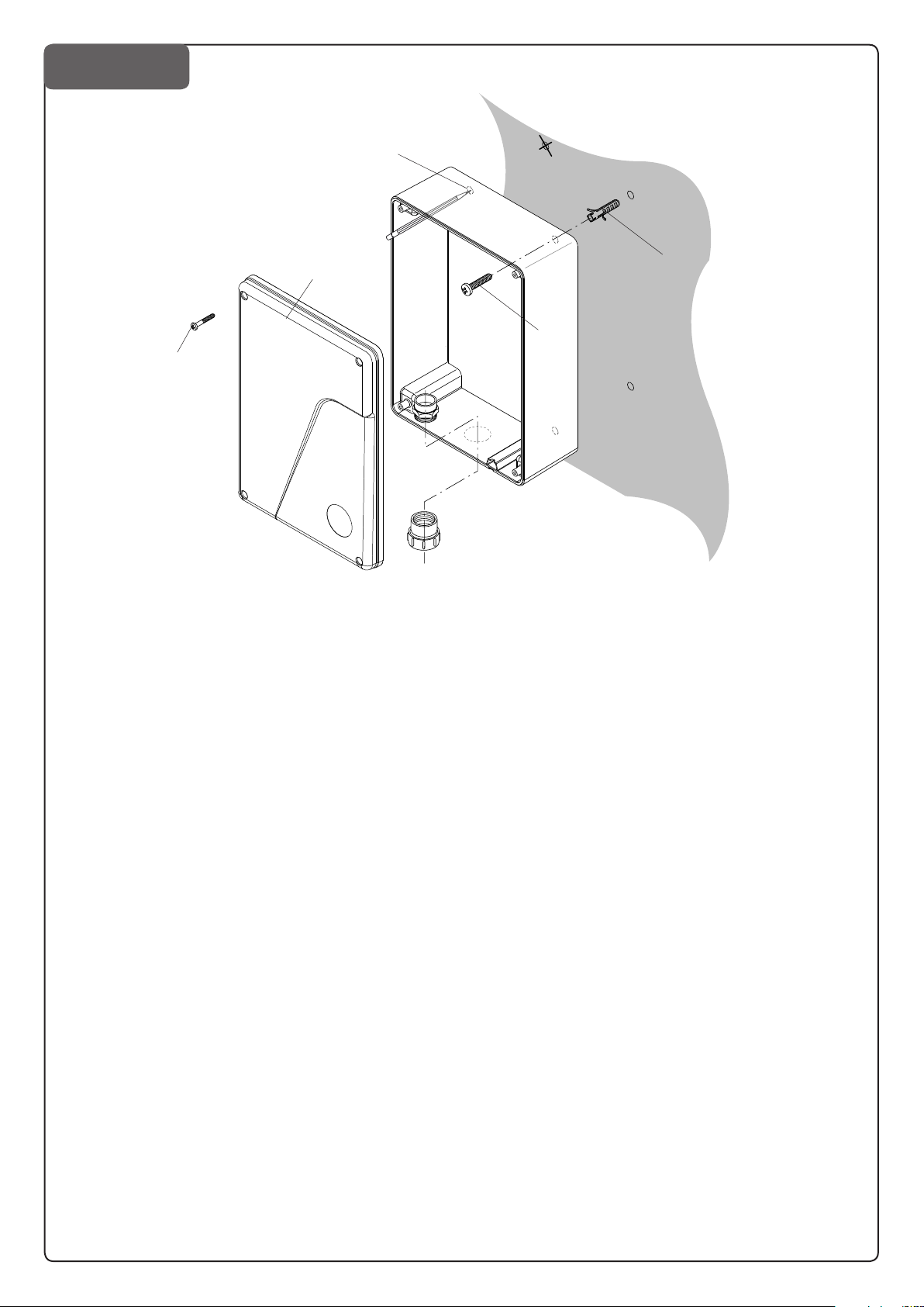
Rimuovere le 4 viti A , quindi rimuovere il coperchio B
Sul fondo del contenitore centrale sono presenti 4 predisposizioni (C) da rompere con un cacciavite.
Posare il fondo alla parete e segnare i 4 punti di foratura.
Eseguire 4 fori ed inserire 4 tasselli (E), fissare la centrale con
le 4 viti D. Tasselli e viti sono fornite in dotazione.
Remove the 4 screws A and then remove cover B
There are 4 set-ups (C) present on the base of the control unit
container, which must be broken using a screwdriver.
Place the base on the wall and mark the 4 drilling points.
Make the 4 holes and insert the 4 plugs (E), fix the control unit
with the 4 screws D. Plugs and screws are supplied.
Entfernen Sie die 4 Schrauben A und nehmen Sie Deckel B ab.
Im Boden des Hauptgehäuses befinden sich 4 vorbereitete Öff-
nungen (C), die mit einem Schraubenzieher aufzubrechen sind.
Halten Sie den Boden an die Wand und zeichnen Sie die 4 Boh-
rungen an.
Führen Sie die 4 Bohrungen aus und setzen Sie 4 Dübel (E) ein.
Fixieren Sie die Steuerung mit den 4 Schrauben D. Dübel und
Schrauben werden mitgeliefert.
Enlever les 4 vis A puis enlever le couvercle B
Au fond du boîtier de la centrale se trouvent 4 ouvertures spéciales (C) qu’il faut creuser à l’aide d’un tournevis.
Appuyer le fond du boîtier contre le mur et marquer avec 4
signes les points de perçage.
Percer les 4 trous et insérer les 4 chevilles (E), fixer la centrale
avec les 4 vis D. Les chevilles et les vis sont fournies en dotation.
Quite los 4 tornillos A, entonces quite la cubierta B
En el fondo de la caja central hay 4 predisposiciones (C) que
hay que romper con un destornillador.
Apoye el fondo a la pared y marque los 4 puntos de perforación.
Realice los 4 agujeros e introduzca los 4 tacos (E), fije la central
con los 4 tornillos D. Se proporcionan los tacos y los tornillos.
Wykręć śruby A i ściągnij pokrywę B.
Śrubokrętem zrób 4 otwory (C)na tylnej ściance skrzynki. Przyłóż
skrzynkę do ściany i zaznacz 4 miejsca na otwory. Wywierć otwory, wsadź 4 kołki(E), przykręć skrzynkę wkrętami (D).
Page 3
SHIELD
ANT
ANT
M1 M2
LAMP
24Vdc
SCA
Photo Test
2CH
SERL
24Vac
24Vac/dc
500mA max
(+) (-)
SWO1/ENC1
SWC1
SWO2/ENC2
SWC2
PHOTO
PHOTC
STOP
PED
P.P.
COM/ENC +
ENC -
COM/ENC+
F1
T 2A
1 2 3 4 5 6 9 10 11 12 13 14 15 16 17 18 19 20 23 24 25 26
3231
+-
RA D IO
U11
Code
____
F1 (230V): 1.6 AT
F1 (115V): 3.15 AT
L
N
1
3
Page 4
4
SWO1/ENC1
SWO2/ENC2
ENC +
ENC -
33323130
+-
RA D I O
U11
M1
+ s -M2+ s -
3+3 x 0.5mm
2
max 10m
2
24V ac 24V ac
COM
NC NO
RX1TX1
24V ac 24V ac
COM
NC NO
RX2TX2
11
24Vac
COM PHOTO COM PHOT-C
24Vac
12 11 1213 18 13 199 10
9 10
test1:on test2:ON
L
N
Service/Zone
Light
230Vac
Relè
24Vac
9 10 11 12
9 10 11 12
SCA
2CH:0ff
serl:0FF
TST1:0FF
TST2:0FF
9 10 11 12
2CH
2CH:0N
serl:0FF
TST1:0FF
TST2:0FF
SERVICE/ZONE LIGHT
serl:0N TST1:0FF
2CH:0FF TST2:0FF
Collegamento ENCODER
ENCODER WIRING
3
4
Page 5

12
EC Declaration of conformity
Declaration pursuant to Directives 2004/108/EC(EMC); 2006/95/EC(LVD)
Manufacturer:
Automatismi Benincà SpA
Address:
Via Capitello, 45 - 36066 Sandrigo (VI) - Italy
Declares that the product:
Command central for 1 24Vdc motor, for single or sliding doors: HEADY 24
is compliant with the conditions of the following EC Directives:
• DIRECTIVE 2004/108/EC OF THE EUROPEAN PARLIAMENT AND COUNCIL of December 15 2004 regarding
the approximation of the legislations of the member States relative to electromagnetic compatibility and that repeals directive
89/336/CEE, according to the following concurred norms:
EN 61000-6-2:2005, EN 61000-6-3:2007.
• DIRECTIVE 2006/95/EC OF THE EUROPEAN PARLIAMENT AND THE COUNCIL of December 12 2006 concerning the approximation of the legislations of the member States relative to electrical material destined to be used within certain
voltage limits, according to the following concurred regulations:
EN 60335-1:2002 + A1:2004 + A11:2004 + A12:2006 + A2:2006 + A13:2008; EN 60335-2-103:2003.
if applicable :
• DIRECTIVE 1999/5/EC OF THE EUROPEAN PARLIAMENT AND THE COUNCIL of March 9 1999 regarding radio
devices and terminal and telecommunications devices and the reciprocal recognisances of their conformity, according to the
following concurred regulations: ETSI EN 301 489-3 V1.4.1 (2002) + ETSI EN 301 489-1 V1.4.1 (2002) + ETSI EN 300 220-3
V1.1.1 (2000) + EN 60950-1 (2001)
Benincà Luigi, Legal manager.
Sandrigo, 02/11/2010.
WARNINGS
This manual has been especially written to be use by
qualified fitters.
None of the information provide in this manual can be
considered as being of interest for the end users.
Preserve this manual for future needs.
The technician has to furnish all the information related to
the step by step function, the manual and the emergency
function of the operator, and to deliver the manual to the
final user.
Foresee on the supply net an onnipolar switch or
selector with distance of the contacts equal or
•
Verify that of the electrical system there is an awry differential interrupter and overcurrent protection.
Some typologies of installation require the connection of
the shutter to be link at a conductive mass of the ground
according to the regulations in force.
superior to 3 mms.
The electrical installation and the operating logic must
comply with the regulations in force.
The leads fed with different voltages must be physically
separate, or they must be suitably insulated with additional
insulation of at least 1 mm.
The leads must be secured with an additional fixture near
the terminals.
During installation, maintenance and repair, interrupt the
power supply before opening the lid to access the electrical parts
Check all the connections again before switching on the
power.
The unused N.C. inputs must be bridged.
The descriptions and the present illustrations in this manual
are not binding. Leaving the essential characteristics of the
product unchanged, the manufacturer reserves himself
the right to bring any change of technical, constructive
or commercial character without undertaking himself to
update the present publication.
Page 6

13
TECHNICAL DATA
Contol unit supply
24 Vdc
Power supply
Output supply
Maximum motor current
Output supply accessories
Protection level
Operating temp.
Radio receiver
Rolling code transmitters supported
230 Vac 50/60 Hz or 115Vac 50/60Hz according to the version
1/2 motor 24Vdc
2.5+2.5 A
24Vdc 500mA max.
IP54
-20°C / +70°C
built in 433,92 MHz confgurabile (rolling-code or programmable + rolling-code)
64
HEADY 24 CONTROL UNIT
AUTOSET FUNCTION
IMPORTANT: The control unit is equipped with the Autoset function to automatically set the main functioning values based on the
type of installation.
The AUTOSET function must be repeated at every function parameter change or upon change of automation conditions. See the
AUTO menu for further information.
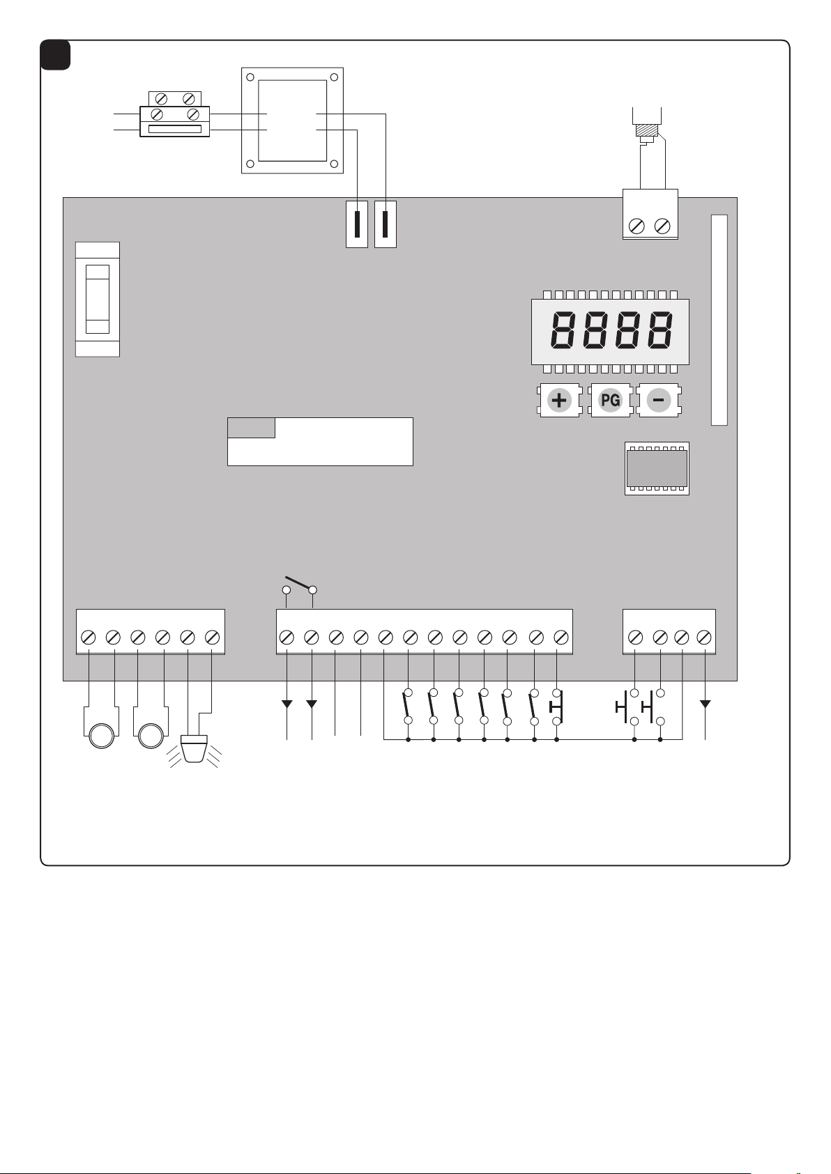
WIRE DIAGRAM
Wire connections shown in Fig. 1 are described hereunder:
Terminal No.
1-2 Motor 1 Connection, motor 1: 24VDC 2.5A max
3-4 Motor 2 Connection, motor 2: 24VDC 2.55A max
5-6 Flashing light Connection, flashing light 24VDC 15W max.
9-10
11-12 24 Vac/dc
13-25 COM/ENC+ Common for limit switch and all the command inlets or encoder power supply.
14 SWO1/ENC1 Motor 1 OPEN limit switch input (N.C. contact) or Motor 1 Encoder connection.
15 SWC1 Motor 1 CLOSE limit switch input, (N.C. Contact)
16 SWO2/ENC2 Motor 2 OPEN limit switch input, (N.C. Contact) or Motor 2 Encoder connection.
17 SWC2 Motor 2 CLOSE limit switch input, (N.C. Contact)
18 PHOTO/BAR
19 PHOTC Input, photocell activated in closing phase only (Normally closed contact)
20 STOP Input, STOP push-button (Normally closed contact)
23 PED
24 Step-by-Step Input, step-by-step push button (Normally open contact)
26 ENC- Input for GND Encoder connection (see Fig.2).
31-32 Antenna Connection to the built-in radio receiver card (31-signal/32-screen).
+ / - 24VAC/dc
Function Description
Normally Open, voltage-free contact, configurable as open gate indicator light, photocell
SCA/
PHOTO TEST/
2 CH
test or second radio channel (see Fig. 4).
For use as “Open gate indicator” the TEST1 and TEST2 logics must be OFF
For use as photocell test it is sufficient to activate one or both TEST logics and connect
the photocells as indicated in Fig.3.
Output, accessory power supply, 24VAC/0.5A max.
IMPORTANT: If the battery charger board is installed, the output (without mains power
connected) has a 24Vdc polarised voltage.
Make sure the devices are correctly connected (i.e. 11:+24Vdc / 12:-0Vdc).
Input, photocell activated in both opening and closing phases
As an alternative, the PHOTO input can be used to connect a safety edge (see BAR log-
ics).
Input, pedestrian push-button (N.O. (Normally Open) contact). It controls the total opening,
motor 1.
Input, 24VAC/24VDC power supply.
In case of use of plug batteries connect the battery charging card as indicated in the specific
installation instructions.
Page 7

14
Extractable Eprom Memory. Contains all the control unit configurations (logics, parameters,
etc.), including the radiotransmitters. In case of faults it is possible to extract Eprom and
insert it into a different control unit, avoiding reprogramming.
U11
CON F IGUR ATIO N
MEMORY
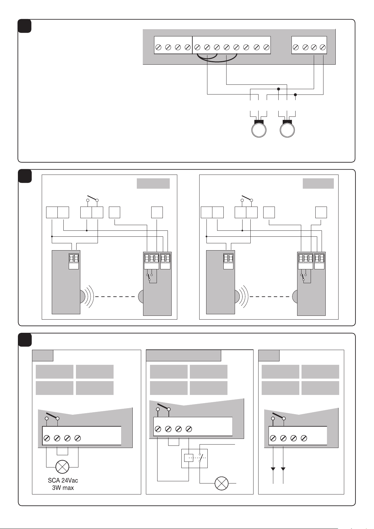
ENCODER WIRING
In case the motor is with Encoder and one wished to connect it to the control unit, carry out the connections indicated in Fig.2, in
this case the SWO1 and SWO2 inputs may not be used as Limit switch inputs.
It is not possible to use the Encoder and the closure Limit switch simultaneously.
Leave SWC1 and SWC2 shorted.
TO CHECK CONNECTIONS
1) Cut-off power supply.
2) Manually release the wings, move them to approx. half-stroke and lock them again.
3) Reset power supply.
4) Send a step-by-step control signal by pressing the <-> push-button.
5) The leeaves must move in OPENING.
In case this does not happen, it is sufficient to invert among them the motor run wires. (1<>2 for M1 motor, and 3<>4 for M2
motor) and, if used, the relative Limit switch inputs (14<>15 for M1 motor, and 16<>17 for M2 motor).
PROGRAMMING
The programming of the various functions of the control unit is carried out using the LCD display on the control unit and setting the
desired values in the programming menus described below.
The parameters menu allows you to assign a numerical value to a function, in the same way as a regulating trimmer.
The logic menu allows you to activate or deactivate a function, in the same way as setting a dip-switch.
Other special functions follow the parameters and logic menus and may vary depending on the type of control unit or the software
release.
TO ACCESS PROGRAMMING:
1 – Press the button <PG>, the display goes to the first menu, Parameters “PAR”.
2 – With the <+> or <-> button, select the menu you want (PAR>LOG>RAD>NMAN>MACI>RES>AUTO>CODE).
3- Press the button <PG>, the display shows the first function available on the menu.
4 - With the <+> or <-> button, select the function you want.
5 - Press the button <PG>, the display shows the value currently set for the function selected.
6 - With the <+> or <-> button, select the value you intend to assign to the function.
7 - Press the button <PG>, the display shows the signal “PRG” which indicates that programming has been completed.
NOTES:
Simultaneously pressing <+> and <-> from inside a function menu allows you to return to the previous menu without making any
changes. Hold down the <+> key or the <-> key to accelerate the increase/decrease of the values.
After waiting 120s the control unit quits programming mode and switches off the display.
When the board is switched on, the software version is displayed for around 5 sec
Hold down the <+> key or the <-> key to accelerate the increase/decrease of the values.
PARAMETERS, LOGIC AND SPECIAL FUNCTIONS
The tables below describe the individual functions available in the control unit.
PARAMETERS (PAR)
MENU FUNCTION
TCA
TM1
TM2
PMo1
PMC1
Automatic closing time. Active only with logic “TCA”=ON.
At the end of the set time the control unit orders a closing manoeuvre.
Operating time, motor 1. The operating time is adjusted at normal speed during
motor 1 opening and closing phases. See Paragraph “Adjustment of the gate
leaf speed”.
By setting the value to 0, the operation is performed with around 2 seconds of
pick-up and then the movement is carried on at reduced speed for the entire
stroke.
Operating time, motor 2. The operating time is adjusted at normal speed during
motor 2 opening and closing phases. See Paragraph “Adjustment of the gate
leaf speed”.
By setting the value to 0, the operation is performed with around 2 seconds of
pick-up and then the movement is carried on at reduced speed for the entire
stroke.
The anti-crash device* (amperometric sensor) operation is adjusted in the opening phase, at normal speed - Motor 1.
The anti-crash device* (amperometric sensor) operation is adjusted in the closing
phase, at normal speed - Motor 1.
MIN-MAX-(Default)
1-240-(40s)
0-99-(5s)
0-99-(5s)
1-99-(50%)**
1-99-(50%)**
MEMO
Page 8

15
PMo2
PMc2
TDMo
TDMC
SLD1
SLD2
Pso1
Psc1
Pso2
Psc2
SeaU
SEAR
* WARNING: AN INCORRECT SETTING OF THESE PARAMETERS MAY RESULT IN AN HAZARD.
COMPLY WITH REGULATIONS IN FORCE!
With motors without limit switch and/or encoder it adjusts the sensitivity of the sensor which causes arrest during
slowing phase.
The anti-crash device* (amperometric sensor) operation is adjusted in the opening phase, at normal speed - Motor 2.
The anti-crash device* (amperometric sensor) operation is adjusted in the closing
phase, at normal speed - Motor 2.
Mot.2 opening delay time.
Regulates the delay time of motor 2 on opening with respect to motor 1
Mot.1 closing delay time
Regulates the delay time of motor 1 on closing with respect to motor 2
Adjusts motor 1 speed during slowing phases. Value expressed in percentage of
normal functioning speed.
Adjusts motor 2 speed during slowing phases. Value expressed in percentage of
normal functioning speed.
The anti-crash device* (amperometric sensor) operation is adjusted in the opening phase, at reduced speed - Motor 1.
The anti-crash device* (amperometric sensor) operation is adjusted in the closing
phase, at reduced speed - Motor 1.
The anti-crash device* (amperometric sensor) operation is adjusted in the opening phase, at reduced speed - Motor 2.
The anti-crash device* (amperometric sensor) operation is adjusted in the closing
phase, at reduced speed - Motor 2.
The intervention threshold of the anti-crashing device (Encoder) during the phase
at normal speed is adjusted.*
0:Off-1:minimum sensitivity - 99: maximum sensitivity
The intervention threshold of the anti-crashing device (Encoder) during braking
is adjusted *.
0:Off-1:minimum sensitivity - 99: maximum sensitivity
1-99-(50%)**
1-99-(50%)**
0-15-(2s)
0-40-(3s)
30-70 (40%)
30-70 (40%)
1-99-(20%)**
1-99-(20%)**
1-99-(20%)**
1-99-(20%)**
0-99-(0%)
0-99-(0%)
** 1: minimum force/torque - 99: maximum force/torque
LOGIC (LOG)
MENU FUNCTION
Enables or disables automatic closing
TCA
IbL
SCL
PP
PRE
Blco
Blc
On: automatic closing enabled
Off: automatic closing disabled
Enables or disables condominium function.
On: condominium function enabled. The step-by-step impulse or transmitter
impulse has no effect during the opening phase.
Off: condominium function disabled.
Enables or disables rapid closing
On: rapid closure is enabled. With open gate, or in the opening phase, the
activation of the photocell causes the automatic closure 3sec after the total
opening of the gate. It is activated only with TCA:ON
Off: rapid closing disabled.
Selects the operating mode of the ”Step by step button” and of the transmitter.
On: Operation: OPEN > CLOSE > OPEN >
Off: Operation: OPEN > STOP > CLOSE > STOP >
Enables or disables pre-blinking.
On: Pre-blinking enabled. Blinking is activated 3s before the motor starts.
Off: Pre-blinking disabled.
Enables or disables the block function in opening.
On: Block function enabled. To use only with motors equipped with Limit
switch. After the intervention of the opening Limit switch the control unit delays
arrest by about 0.5s, so to allow a better strike of the shutter on the stop locks.
Off: Block function disabled
Enables or disables the block function in closing.
On: Block function enabled. To use only with motors equipped with Limit
switch. After the intervention of the opening Limit switch the control unit delays
arrest by about 0.5s, so to allow a better strike of the shutter on the stop locks.
Off: Block function disabled.
ON-OFF-(Default)
(ON)
(OFF)
(OFF)
(OFF)
(OFF)
(OFF)
(OFF)
MEMO
Page 9

16
1mot
Cvar
OPCL
2ch
serl
BAR
TST1
TST2
TSTm
rem
Select the 1/2 motors operating mode:
On: Only motor 1 operating.
Off: Both motors operating.
The code programmable transmitters is enabled or disabled.
On: Radio receiver enabled only for rolling-code transmitters.
Off: Receiver enabled for rolling-code and programmable code transmitters
(self-learning and Dip Switch).
PP input as OPEN and PED input as CLOSED are enabled or disabled.
On: PP input is enabled as OPEN and PED input is enabled as CLOSED.
Off: PP and PED inputs are enabled with their function.
Enables or disables the second radio channel on terminals 9/10.
On: Exit configured with function as second radio channel.
Off: Exit takes on function of service light (see Fig.3).
The service light function is enabled or disabled on the 9/10 output (see Fig.3).
On: This output has the function of service light. At each operation, the output
supplies 24VAC for around 60sec.
The counting of the TLS time starts when the motor stops.
Use an auxiliary relay to control the light.
Off: The output features the SCA function, open gate light: light off with closed
gate, flashing light with moving gate, light on with open gate. See wire diagram.
The operating mode of input 13/18 (PHOTO) is selected.
On: Input for the connection of the mechanical safety edge (Normally Closed
(N..C.) contact), activated in both opening and closing phases. The activation of
the safety edge causes the gate stop and its movement reversion for around 3
seconds. The logics TST1 mush be OFF:
Off: Input for the connection of the photocell (N.C. contact), activated in both
opening and closing phases. When the photocell switches on (open contact), the
gate movement will stop. When the photocell switches off (closed contact), the
control unit will always send an opening control signal to the system, even if the
photocell was activated during closure.
Enables or disables checking of photocells on PHOTO input, active both in closing and in opening.
On: Check enabled. If the check has a negative result, no manoeuvre is commanded. See Fig.3 - “PHOTO TEST”.
Off: Checking of photocells disabled at each manoeuvre.
Enables or disables checking of photocells on PHOTC inputs, active only in closing.
On: Check enabled. If the check has a negative result, no manoeuvre is commanded. See Fig.3 - “PHOTO TEST”.
Off: Checking of photocells disabled at each manoeuvre.
Enables or disables motors check.
On: Check enabled. If the check has a negative result, no manoeuvre is commanded.
Off: Check disabled.
(Enables or disables remote radiotransmitters learning, as indicated in the paragraph “Remote transmitters learning”.
On: Remote learning enabled.
Off: Remote learning not enabled.
(OFF)
(OFF)
(OFF)
(OFF)
(OFF)
(OFF)
(OFF)
(OFF)
(OFF)
(OFF)
RADIO (RADi)
MENU FUNZIONE
By selecting this function, the receiver goes in waiting (Push) for a transmitter code to assign to the step-step function.
PP
2Ch
ped
Press the key of the transmitter to assign to this function.
If the code is valid, it is memorised and the message OK is displayed
If the code is not valid, the message Err is displayed
By selecting this function, the receiver goes into waiting (Push) for a transmitter code to assign to the second radio
channel.
Press the key of the transmitter to assign to this function.
If the code is valid, it is memorised ad the OK message is displayed
If the code is not valid, the message Err is displayed.
By selecting this function, the receiver goes into waiting (Push) for a transmitter code to assign to the pedestrian
opening function.
Press the key of the transmitter to assign to this function.
If the code is valid, it is memorised ad the OK message is displayed
If the code is not valid, the message Err is displayed.
Page 10

17
By selecting this function, the receiver goes into waiting (Push) for a transmitter code to erase from the memory.
CLR
RTR
If the code is valid, it is erased and the message OK is displayed
If the code is not valid or not present in memory, the message Err is displayed
Completely erases memory of the receiver. Confirmation of the operation is requested.
By selecting this function the receiver goes into waiting (Push) for a new PGM pressure to confirm the operation.
At end of erasing the OK message is displayed
CYCLES NUMBER (Nman)
Displays the number of complete cycles (open+close) carried out by the automation.
When the <PG> button is pressed for the first time, it displays the first 4 figures, the second time it shows the last 4. Example
<PG> 0012 >>> <PG> 3456: made 123.456 cycles.
RESET (RES)
RESET of the control unit. ATTENTION!: Returns the control unit to the default values.
Pressing the <PG> button for the first time causes blinking of the letters RES, pressing the <PG> button again resets the control
unit. Note: The transmitters are not erased from the receiver nor is the access password.
All the logics and all the parameters are brought back to default values, it is therefore necessary to repeat the autoset procedure.
AUTOSET (AUTO)
This function must be used to set the optimal automation function values, and at the end of the procedure, it sets medium values
of COUPLING, WORK TIME and SLOWING. To carry out autoset, proceed as follows:
a) Ascertain that no obstacles of any nature are present in the manoeuvre area, if necessary, block off the area in order to prevent
access from people, animals, vehicles, etc.
During autoset phase, the anti-crushing function is not active.
b) Select the AUTO function and press OK.
c) Select with the <+> or <-> button the submenu, NOLS, LSW or ENC based on the presence of Limit switch and/or encoder:
NOLS: if the motor is without Limit switch and encoder
LSW: if the motor is equipped with Limit switch and without encoder
ENC: if the motor is equipped with encoder and without Limit switch
d) once selected press OK to begin the autoset phase.
The control unit carries out a series of manoeuvres for learning of the run of the leves and for parameter configuration.
Initially both the leaves are brought to opening position, then after some opening and closing manoeuvres at different speeds, of
one or both the shutters, the control unit displays the message OK. In case the operation has no positive result, the message ERR
is displayed. Repeat the operation after re-checking the wiring and the eventual presence of obstacles.
In case parametersTM1/TM2 or the speed are changed, repeat the autoset procedure.
During the manoeuvres the display will show some abbreviations: OPM1/OPM2 during opening of the motor 1 or 2 and CLM1/
CLM2 during closing of motor 1 or 2.
PROTECTION CODE (CODE)
It allows to type in an access protection code to the programming of the control unit.
A four-character alphanumeric code can be typed in by using the numbers from 0 to 9 and the letters A-B-C-D-E-F.
The default value is 0000 (four zeros) and shows the absence of a protection code.
While typing in the code, this operation can be cancelled at any moment by pressing keys + and – simultaneously. Once the
password is typed in, it is possible to act on the control unit by entering and exiting the programming mode for around 10 minutes
in order to allow adjustments and tests on functions.
By replacing the 0000 code with any other code, the protection of the control unit is enabled, thus preventing the access to any
other menu. If a protection code is to be typed in, proceed as follows:
- select the Code menu and press OK.
- the code 0000 is shown, also in the case a protection code has been previously typed in.
- the value of the flashing character can be changed with keys + and -.
- press OK to confirm the flashing character, then confirm the following one.
- after typing in the 4 characters, a confirmation message “CONF” appears.
- after a few seconds, the code 0000 appears again
- the previously stored protection code must be reconfirmed in order to avoid any accidental typing in.
If the code corresponds to the previous one, a confirmation message “OK” appears.
The control unit automatically exits the programming phase. To gain access to the Menus again, the stored protection code must
be typed in.
IMPORTANT: TAKE NOTE of the protection code and KEEP IT IN A SAFE PLACE for future maintenance operations.
To remove a code from a protected control unit it is necessary to enter into programming with the password
and bring the code back to the 0000 default value. IF YOU LOOSE THE CODE, PLEASE CONTACT THE AUTHOR-
ISED SERVICE CENTER FOR THE TOTAL RESET OF THE CONTROL UNIT.
Page 11

18
TRANSMITTERS REMOTE LEARNING
PHOT
SWC1
STOP
SWO1 SWO2
SWC2
PHOT-C
P.P. PED
If an already memorised transmitter is available in the receiver it is possible to carry out remote radio learning (without needing to
access the control unit).
IMPORTANT: The procedure must be carried out with leaves in opening during TCA pause or with an open gate if the TCA
logic is OFF. The REM logic must be ON.
Proceed as follows:
1 Press the hidden key of the transmitter which is already memorised.
2 Press, within 5s, the key of the corresponding transmitter which is already memorised to associate to the new transmitter. The
flashing light will turn on.
3 Press within 10s the hidden key of the new transmitter.
4 Press, within 5s, the key of the new transmitter to associate to the channel chosen at point 2. The flashing light will turn off.
5 The receiver memorised the new transmitter and immediately exits from programming.
FUSES
F1: Accessory power supply safety fuse.
F2: General safety fuse
EMERGENCY BATTERY
An optional accessory is available for control unit power supply in case of absence of power.
The kit is made up of a battery charging board and two 12V rechargeable batteries, fixing clamps, screws and wiring.
For further information, refer to the instructions supplied with the accessory.
DIAGNOSTICS
One segment of the display is linked to each input. In the event of failure it switches on
according to the following scheme.
N.C. inputs are represented by the vertical segments. N.O. inputs are represented by
the horizontal segments.
The control unit sees the message AMP1 or AMP2 in case of anti-crushing ammeter
sensor intervention.
ERROR MESSAGES
Some messages that are displayed in case of function anomalies are listed as follows:
Amp1
Amp2
Err1
Err2
Err3
Err4
Err5
Err7
Err8
thrm
Obstacle error motor 1/anti-crushing Check presence of obstacles on motor 1 leaf run
Obstacle error motor 2/anti-crushing Check presence of obstacles on motor 2 leaf run
Motor 1 circuit checking error Check motor 1 connections
Motor 2 circuit checking error Check motor 2 connections
error/fault power circuit Request technical assistance and eventually replace control unit.
PHOTO/BAR photocell checking error
PHOTC photocell checking error
Error active stop (during autoset) In autoset phase, the STOP input has intervened.
Error active input (during autoset) In autoset phase a PP/Open/Close input has intervened.
Motor thermal protection intervention
Check connections, PHOTO/BAR photocell alignment or presence of
obstacles.
Check connections, PHOTC photocell alignment or presence of obstacles.
Wait for motor cooling, in case reset does not take place, motor replacement may be necessary
WASTE DISPOSAL
If the product must be dismantled, it must be disposed according to regulations in force regarding the differentiated waste disposal
and the recycling of components (metals, plastics, electric cables, etc..). For this operation it is advisable to call your installer or a
specialised company.
 Loading...