


Honeywell International Inc.
23500 W 105th Street
Olathe, KS 66061
U.S.A
CAGE: 22373
Telephone: (800) 601-3099 (U.S.A./Canada)
Telephone: (602) 365-3099 (International)
AV8OR
User’s Guide
Pub. No.D200803000008 Page -i Rev 2 Dec 2008.
© Honeywell International Inc. Do not copy without express permission of
Honeywell.

AV8OR User Guide Honeywell-Confidential
Honeywell-Confidential
THIS COPYRIGHTED WORK AND ALL INFORMATION
ARE THE PROPERTY OF HONEYWELL
INTERNATIONAL INC., CONTAIN TRADE SECRETS
AND MAY NOT, IN WHOLE OR IN PART, BE USED,
DUPLICATED, OR DISCLOSED FOR ANY PURPOSE
WITHOUT PRIOR WRITTEN PERMISSION OF
HONEYWELL INTERNATIONAL INC. ALL RIGHTS
RESERVED.
Honeywell Materials License Agreement
The documents and information contained herein ("the
Materials") are the proprietary data of Honeywell
International Inc. and Honeywell Intellectual Properties
Inc (collectively "Honeywell"). These Materials are
provided for the exclusive use of Honeywell Service
Centers; Honeywell-authorized repair facilities;
operators of Honeywell aerospace products subject to
an applicable product support agreement, their wholly
owned-subsidiaries or a formally designated third
party service provider thereunder; and direct
recipients of Materials from Honeywell's Aerospace
Technical Publication Distribution. The terms and
conditions of this License Agreement govern your use
of these Materials, except to the extent that any terms
and conditions of another applicable agreement with
Honeywell regarding the operation, maintenance, or
repair of Honeywell aerospace products conflict with
the terms and conditions of this License Agreement, in
which case the terms and conditions of the other
agreement will govern. However, this License
Agreement will govern in the event of a conflict
between its terms and conditions and those of a
purchase order or acknowledgement.
1. License Grant - If you are a party to an applicable product
support agreement, a Honeywell Service Center agreement, or
an authorized repair facility agreement, Honeywell hereby grants
Pub. No.D200803000008 Page -ii Rev 2 Dec 2008.
© Honeywell International Inc. Do not copy without express permission of
Honeywell.

AV8OR User Guide Honeywell-Confidential
you a limited, non-exclusive license to use these Materials to
operate, maintain, or repair Honeywell aerospace products only
in accordance with that agreement.
If you are a direct recipient of these Materials from Honeywell's
Aerospace Technical Publication Distribution and are not a party
to an agreement related to the operation, maintenance or repair
of Honeywell aerospace products, Honeywell hereby grants you a
limited, non-exclusive license to use these Materials to maintain
or repair the subject Honeywell aerospace products only at the
facility to which these Materials have been shipped ("the
Licensed Facility"). Transfer of the Materials to another facility
owned by you is permitted only if the original Licensed Facility
retains no copies of the Materials and you provide prior written
notice to Honeywell.
2. Rights In Materials - Honeywell retains all rights in these
Materials and in any copies thereof that are not expressly granted
to you, including all rights in patents, copyrights, trademarks, and
trade secrets. No license to use any Honeywell trademarks or
patents is granted under this License Agreement.
3. Confidentiality - You acknowledge that these Materials
contain information that is confidential and proprietary to
Honeywell. You agree to take all reasonable efforts to maintain
the confidentiality of these Materials.
4. Assignment And Transfer - This License Agreement may be
assigned to a formally designated service designee to the extent
allowed under an applicable product support agreement or
transferred to a subsequent owner or operator of an aircraft
containing the subject Honeywell aerospace products. However,
the recipient of any such assignment or transfer must assume all
of your obligations under this License Agreement. No assig nment
or transfer shall relieve any party of any obligation that such party
then has hereunder.
5. Copies of Materials - Unless you have the express written
permission of Honeywell, you may not make or permit making of
copies of the Materials. Notwithstanding the foregoing, you may
make copies of only portions of the Material for your internal use.
You agree to return the Materials and any copies thereof to
Honeywell upon the request of Honeywell.
6. Term - This License Agreement is effective until terminated as
set forth herein. This License Agreement will terminate
immediately, without notice from Honeywell, if you fail to comply
with any provision of this License Agreement or will terminate
Pub. No.D200803000008 Page -iii Rev 2 Dec 2008.
© Honeywell International Inc. Do not copy without express permission of
Honeywell.

AV8OR User Guide Honeywell-Confidential
simultaneously with the termination or expiration of your
applicable product support agreement, authorized repair facility
agreement, or your formal designation as a third party service
provider. Upon termination of this License Agreement, you will
return these Materials to Honeywell without retaining any copies
and will have one of your authorized officers certify that all
Materials have been returned with no copies retained.
7. Remedies - Honeywell reserves the right to pursue all
available remedies and damages resulting from a breach of this
License Agreement.
8. Limitation of Liability - Honeywell does not make any
representation regarding the use or sufficiency of the Materials.
THERE ARE NO OTHER WARRANTIES, WHETHER WRITTEN
OR ORAL, EXPRESS, IMPLIED OR STATUTORY, INCLUDING,
BUT NOT LIMITED TO, (i) WARRANTIES ARISING FROM
COURSE OF PERFORMANCE, DEALING, USAGE, OR TRADE,
WHICH ARE HEREBY EXPRESSLY DISCLAIMED, OR (ii)
WARRANTIES AGAINST INFRINGEMENT OF INTELLECTUAL
PROPERTY RIGHTS OF THIRD PARTIES, EVEN IF
HONEYWELL HAS BEEN ADVISED OF ANY SUCH
INFRINGEMENT. IN NO EVENT WILL HONEYWELL BE LIABLE
FOR ANY INCIDENTAL DAMAGES, CONSEQUENTIAL
DAMAGES, SPECIAL DAMAGES, INDIRECT DAMAGES, LOSS
OF PROFITS, LOSS OF REVENUES, OR LOSS OF USE, EVEN
IF INFORMED OF THE POSSIBILITY OF SUCH DAMAGES. TO
THE EXTENT PERMITTED BY APPLICABLE LAW, THESE
LIMITATIONS AND EXCLUSIONS WILL APPLY REGARDLESS
OF WHETHER LIABILITY ARISES FROM BREACH OF
CONTRACT, WARRANTY, TORT (INCLUDING BUT NOT
LIMITED TO NEGLIGENCE), BY OPERATION OF LAW, OR
OTHERWISE.
9. Controlling Law - This License shall be governed and
construed in accordance with the laws of the State of New York
without regard to the conflicts of laws provisions thereof. This
license sets forth the entire agreement between you and
Honeywell and may only be modified by a writing duly executed
by the duly authorized representatives of the parties.
Pub. No.D200803000008 Page -iv Rev 2 Dec 2008.
© Honeywell International Inc. Do not copy without express permission of
Honeywell.

AV8OR User Guide Honeywell-Confidential
Revision History and Instructions
Manual AV8OR User’s Guide
Revision 2, December 2008
Summary
GoFly:
This user guide supports the 0104 release of GoFly
Added information on disposal of battery
Added an “Connection to External Devices” section in Chapter 2
Weather page now only shows if enabled in Device Setup
Added Traffic Page text and figures
Added additional information about the Aircraft Symbol
Revised Image Overlays on Map Page text and figures to add
METARs and Lightning
Added Weather Caution
Added Traffic Mini-Targets Data Field text and figure
Added additional text and figure for Vertical profiles on Smart Profile
function
Added additional text and figure for Waypoint Alert
Added additional text and figures for Turn Anticipation
Added additional text and figures for creating a user waypoi nt
Added new section for Flight Logging
Added new text and figures for Graphical METARs
Added new text and figures for Graphical AIRMETs
Added new text and figures for Graphical SIGMETs
Added new text and figures for Graphical Conv-SIGMETs
Added new text and figures for Graphical PIREPs
Added new text and figures for Graphical METARs
Added new text and figures for Text TAFs
Added new text and figures for Text PIREPs
Added new text and figures for Text AIRMETs
Added new text and figures for Text SIGMETs
Added new text and figures for Text Conv-SIGMETs
Added new Section for Traffic Function
Added text for SUA Alerting, SUA buffer and SUA Display Filtering to
Navigation Setup page
Pub. No.D200803000008 Page -v Rev 2 Dec 2008.
© Honeywell International Inc. Do not copy without express permission of
Honeywell.

AV8OR User Guide Honeywell-Confidential
Added new text and figures to Device Setup section for Traffic and
NMEA Output setup
Added NMEA RS-232 serial output
GoDrive:
Revised figures to show correct size format
Deleted icons that are not available in GoDrive
Added advanced features for GoDrive 8.3 section.
Appendix:
Revised Downloading Files from PC section
Added Connection to an External Traffic Source section
Pub. No.D200803000008 Page -vi Rev 2 Dec 2008.
© Honeywell International Inc. Do not copy without express permission of
Honeywell.

AV8OR User Guide Honeywell-Confidential
Revision History and Instructions
Manual AV8OR User’s Guide
Revision 1, September 2008
Summary
Added additional information on Map Zooming
Added additional information on OBS Course
Added text and figures for use of Victor Airways in Flight Plans
After activating a flight plan, the Map page is shown instead of the
Main Menu page
Added additional information about overlaid products on the
NEXRAD Composite Reflectivity page
Added text and figure for Common Map Data Sources on the Map
Information page
Added text and figure for Weather Status Page
Pub. No.D200803000008 Page -vii Rev 2 Dec 2008.
© Honeywell International Inc. Do not copy without express permission of
Honeywell.

AV8OR User Guide Honeywell-Confidential
Revision History and Instructions
Manual AV8OR User’s Guide
Revision 0, July 2008
Part Number
This is the original release of this publication.
Pub. No.D200803000008 Page -viii Rev 2 Dec 2008.
© Honeywell International Inc. Do not copy without express permission of
Honeywell.

AV8OR User Guide Honeywell-Confidential
Copyright - Notice
Copyright 2008, Honeywell International Inc. All rights reserved.
Honeywell is a registered trademark of Honeywell International
Inc.
All other marks are owned by their respective companies.
Pub. No.D200803000008 Page -ix Rev 2 Dec 2008.
© Honeywell International Inc. Do not copy without express permission of
Honeywell.


AV8OR User’s Guide Table of Contents
Table of Contents
1. INTRODUCTION .................................................................... 1-1
Honeywell Customer Support ..................................................... 1-2
Honeywell Aerospace Technical Publications ............................ 1-3
2. GETTING STARTED.............................................................. 2-1
UNIT OVERVIEW ....................................................................... 2-1
Displays and Controls ............................................................ 2-1
Supplied Equipment ............................................................... 2-4
Optional Equipment ................................................................ 2-4
Charging the internal battery .................................................. 2-5
Understanding Terms ......................................................... 2-6
Turning AV8OR on/off ............................................................ 2-7
AV8OR Sleep Mode ........................................................... 2-8
Turn Sleep Mode On and Off ............................................. 2-8
Main Menu .............................................................................. 2-8
Getting satellite signals .......................................................... 2-9
View GPS status from Settings .......................................... 2-9
3. AVIATION MODE OPERATION ............................................ 3-1
BASIC OPERATION ................................................................... 3-1
Aviation Mode ......................................................................... 3-1
Program Startup ................................................................. 3-1
Demo Mode ........................................................................ 3-4
Aviation Main Menu Page .................................................. 3-5
VFR MOVING MAP FUNCTION ............................................... 3-10
Main Map Display Window ................................................... 3-10
Data Fields ................................................................... 3-18
VFR Moving Map Operation ................................................. 3-25
Map Zooming ................................................................... 3-25
Map View ......................................................................... 3-25
Smart Profile ................................................................ 3-26
Auto Zoom ................................................................... 3-27
Change View ............................................................... 3-28
NEAREST – Select Nearest Destination: .................... 3-30
Waypoint Alert .................................................................. 3-33
Turn Anticipation .............................................................. 3-34
DIRECT-TO Navigation .................................................... 3-35
Create a Direct-To course from the Map ..................... 3-35
Create a Direct-To course from the keyboard entry (No
Flight Plan) ................................................................... 3-37
Re-center aircraft when Direct-To is already enabl ed . 3-39
Pub. No.D200803000008 Page –TC 1 Rev 2 Dec 2008.
© Honeywell International Inc. Do not copy without express permission of
Honeywell.

AV8OR User’s Guide Table of Contents
Bypass a WPT with a flight plan active ........................ 3-39
Enter a Direct-To WPT with a flight plan active. .......... 3-41
PTR MENU....................................................................... 3-43
Create a User Waypoint .............................................. 3-43
Center the Map around Pointer Position ..................... 3-45
PTR MENU – DIRECT-TO Navigation ............................. 3-46
To select a user defined point on the map: ................. 3-47
PTR MENU – OBS Navigation ......................................... 3-47
To select a NAVAID point on the map: ........................ 3-47
To select a user defined point on the map: ................. 3-48
Center Map ...................................................................... 3-50
Center To WPT/Center Aircraft .................................... 3-50
Selectable GPS Data Source ...................................... 3-51
AUTONAV ........................................................................ 3-51
STOP WATCH ................................................................. 3-52
FLIGHT PLAN FUNCTION ....................................................... 3-54
User WPTS ........................................................................... 3-54
User Airport Entry ............................................................. 3-56
Creating New Flight Plan using the Virtual Keyboard .......... 3-58
Inserting Victor Airways into the Flight Plan ......................... 3-62
Creating New Flight Plan using MAP Selections ................. 3-64
Stored Flight Plans Processing ............................................ 3-68
EDIT FPLAN .................................................................... 3-69
DATA VIEW Mode ....................................................... 3-69
MAP VIEW Mode ......................................................... 3-70
FPLAN ADMIN ................................................................. 3-71
COPY FPLAN .............................................................. 3-71
NEW FPLAN ................................................................ 3-71
INVERT FPLAN ........................................................... 3-71
DELETE FPLAN .......................................................... 3-73
FLY FPLAN ...................................................................... 3-73
Active Flight Plan ......................................................... 3-75
Flight Logging ....................................................................... 3-76
Bendix/King flight log ........................................................ 3-76
Jeppesen FliteStar flight log ............................................. 3-76
Google Earth flight log ...................................................... 3-77
WEATHER FUNCTION ............................................................ 3-78
Hardware Accessory ............................................................ 3-78
Receiving Weather Data....................................................... 3-78
Choose Product .................................................................... 3-79
NEXRAD Composite Reflectivity ..................................... 3-81
Pub. No.D200803000008 Page –TC 2 Rev 2 Dec 2008.
© Honeywell International Inc. Do not copy without express permission of
Honeywell.

AV8OR User’s Guide Table of Contents
NEXRAD Map Setup ................................................... 3-81
Graphical AIRMETs ......................................................... 3-86
Graphical SIGMETs ......................................................... 3-88
Graphical Conv-SIGMETs ............................................... 3-90
Graphical PIREPs ............................................................ 3-92
Text METARs ................................................................... 3-94
Text TAFs ......................................................................... 3-95
Text PIREPs ..................................................................... 3-96
Text AIRMETs .................................................................. 3-97
Text SIGMETs .................................................................. 3-98
Text Conv-SIGMETs ........................................................ 3-99
Legend ................................................................................ 3-100
TRAFFIC FUNCTION ............................................................. 3-102
Hardware Accessory .......................................................... 3-102
Traffic Main Page ............................................................... 3-103
Fields on The Traffic Page: ............................................ 3-103
Traffic Setup ................................................................... 3-104
Flight Level................................................................. 3-105
Enable/Disable Pop-UP ............................................. 3-105
MESSAGES FUNCTION ........................................................ 3-108
Notepad/Checklist .............................................................. 3-110
SYSTEM SETUP FUNCTION ................................................ 3-113
System Setup Menu ........................................................... 3-113
General System Setup ................................................... 3-114
Map Setup ...................................................................... 3-116
Navigation Setup ............................................................ 3-121
Data Field Setup ............................................................ 3-125
Flight Plan Data Setup ................................................... 3-127
Demo Mode Setup ......................................................... 3-128
Device Setup .................................................................. 3-130
Status Page ............................................................... 3-131
NMEA Output Setup ....................................................... 3-136
NMEA Output Setup Options: .................................... 3-137
Transmit Default NMEA Sentences: .......................... 3-138
Transmit Selected NEMA Sentences ........................ 3-138
Shut Down .......................................................................... 3-139
4. AUTOMOTIVE MODE OPERATION ..................................... 4-1
Warnings and Safety information................................................ 4-1
Glossary ...................................................................................... 4-2
GETTING STARTED .................................................................. 4-4
Simple and Advanced modes ................................................. 4-6
Pub. No.D200803000008 Page –TC 3 Rev 2 Dec 2008.
© Honeywell International Inc. Do not copy without express permission of
Honeywell.

AV8OR User’s Guide Table of Contents
Soft Keys and Controls on the screen .................................... 4-8
Using keyboards .......................................................... 4-10
Additional Controls ....................................................... 4-11
Using the Map .............................................................. 4-12
Checking the Details of a Map Location ...................... 4-13
Manipulating the Map .................................................. 4-14
Status Information and Hidden Controls on the Map... 4-16
Using the Cursor (the selected map location) ............. 4-22
Advanced Functions ............................................................. 4-23
Smart Zoom ................................................................. 4-23
Position Markers .......................................................... 4-24
Current GPS Position and Lock-on-Road .................... 4-24
Returning to Normal Navigation ................................... 4-24
Selected Location (Cursor) .......................................... 4-25
Original Position in the Cursor Menu ........................... 4-25
Daytime and night color schemes................................ 4-26
Color scheme in tunnels .............................................. 4-26
Route Calculation and Recalculation ........................... 4-26
Itinerary ........................................................................ 4-27
Track Logs ................................................................... 4-29
Route demonstration ................................................... 4-30
POI (Points of Interest) ................................................ 4-30
Saving POI ................................................................... 4-31
Managing POI .............................................................. 4-31
Road Safety Cameras ................................................. 4-31
Saving Road Safety Cameras ..................................... 4-32
Camera Warning .......................................................... 4-32
Camera Types ............................................................. 4-32
Camera Directions ....................................................... 4-34
Speed limit warning ..................................................... 4-35
Advanced Features in GoDrive Version 8.3 ............................. 4-35
ROUTE Navigation ................................................................... 4-37
Selecting the Destination of a Route .................................... 4-37
Selecting the Cursor as the destination ....................... 4-37
Entering an address or part of an address .................. 4-38
Entering an Address (Europe) ..................................... 4-38
Entering an Address (North America, Australia) .......... 4-40
Entering an Address if house numbering is restarted . 4-42
Enter an Address without knowing the district/suburb . 4-44
Selecting an Intersection as the Destination ............... 4-46
Selecting a City Center as the Destination .................. 4-47
Pub. No.D200803000008 Page –TC 4 Rev 2 Dec 2008.
© Honeywell International Inc. Do not copy without express permission of
Honeywell.

AV8OR User’s Guide Table of Contents
Entering an Address with a Postal Code ..................... 4-48
Tips on Entering Addresses Quickly ............................ 4-50
Selecting the destination from your Favorites ............. 4-50
Selecting the destination from the POIs ...................... 4-51
Selecting the destination with saved POI search criteria 4-
53
Selecting the destination from the History ................... 4-53
Selecting the destination by entering its coordinate .... 4-54
Creating a Multi-point Route (inserting a Via Point) ............. 4-55
Creating a Multi-point Route (Append a New Destination) .. 4-56
Editing the Route .................................................................. 4-57
Viewing Whole Route on the Map (Fit-to-Screen) ................ 4-58
Watching the Simulation of the Route .................................. 4-58
Enabling Safety Mode .......................................................... 4-59
Pausing the Active Route ..................................................... 4-59
Deleting the Next Via Point from the Route ......................... 4-59
Deleting the Active Route ..................................................... 4-60
Using Track Logs .................................................................. 4-60
Recording the travelled path (creating a Track Log) ... 4-61
Simulating a Track Log on the map ............................. 4-61
Changing the color of a Track Log .............................. 4-62
Saving a Route ..................................................................... 4-62
Loading a Saved Route ........................................................ 4-62
Reference book (Advanced mode) ........................................... 4-64
Map Screen .......................................................................... 4-65
Icons on the map ......................................................... 4-69
Battery, GPS Position Quality, Vehicle Type Indicator 4-70
Status Indicator Strip ................................................... 4-71
Next two Route Events (Turn Preview fields) .............. 4-72
Objects on the map .......................................................... 4-74
Streets and Roads ....................................................... 4-74
Elements of the Active Route ...................................... 4-74
Detour menu ................................................................ 4-76
Cursor menu ................................................................ 4-77
Position menu .............................................................. 4-80
Route Information screen ............................................ 4-80
Trip Information screen ................................................ 4-83
Trip Computer screen .................................................. 4-88
Quick menu .................................................................. 4-88
GPS data screen ......................................................... 4-91
Find menu ............................................................................. 4-94
Pub. No.D200803000008 Page –TC 5 Rev 2 Dec 2008.
© Honeywell International Inc. Do not copy without express permission of
Honeywell.

AV8OR User’s Guide Table of Contents
Route menu .......................................................................... 4-95
Manage Menu .................................................................. 4-96
Manage Saved Routes ................................................ 4-97
Manage History ............................................................ 4-97
Manage Track Logs ..................................................... 4-98
Manage Favorites ........................................................ 4-99
Manage POIs ............................................................... 4-99
Manage Saved Search Criteria .................................. 4-101
User Data Management ............................................. 4-102
Settings Menu ..................................................................... 4-103
Map Screen Settings ................................................. 4-105
Sound Settings........................................................... 4-106
Route Planning Options ............................................. 4-107
Regional Settings ....................................................... 4-110
Navigation Settings .................................................... 4-111
Warning Settings ....................................................... 4-113
GPS Settings ............................................................. 4-114
Menu Settings ............................................................ 4-115
Device Settings .......................................................... 4-116
Track Log Settings ..................................................... 4-117
5. MULTIMEDIA ......................................................................... 5-1
Music Player ............................................................................... 5-1
Photos ......................................................................................... 5-2
Movie player ................................................................................ 5-4
Ebook Reader ............................................................................. 5-5
Downloading Multimedia Files .................................................... 5-6
6. SYSTEM SETTINGS .............................................................. 6-1
GPS Status ................................................................................. 6-1
Backlight Brightness ................................................................... 6-1
Backlight control bar ............................................................... 6-2
Backlight shutdown setting ..................................................... 6-2
Volume ........................................................................................ 6-2
Enable/disable audio output ................................................... 6-3
Volume control bar ................................................................. 6-3
System Info ................................................................................. 6-3
Bluetooth ..................................................................................... 6-4
7. APPENDIX ............................................................................. 7-1
Acronyms and Abbreviations ...................................................... 7-1
Downloading/Uploading files from/To PC ................................... 7-4
Connection to An External GPS Source ..................................... 7-7
Bendix/King KLN-94 ............................................................... 7-7
Pub. No.D200803000008 Page –TC 6 Rev 2 Dec 2008.
© Honeywell International Inc. Do not copy without express permission of
Honeywell.

AV8OR User’s Guide Table of Contents
Garmin© GNS 430/430W/530/530W ..................................... 7-7
Connection to An External Weather Source ............................... 7-9
Bendix/King KDR-610 Setup .................................................. 7-9
WxWorx XM Weather Receiver Serial Setup ....................... 7-11
WxWorx XM Weather Receiver Bluetooth Setup ................. 7-12
Connection to An External Traffic Source ................................ 7-17
Zaon XRX - Serial Setup ...................................................... 7-17
Configuration of the Zaon XRX ........................................ 7-17
Configuration of AV8OR................................................... 7-17
External Flight Plans ................................................................. 7-19
Jeppesen FliteStar© PC Application ................................... 7-19
Pub. No.D200803000008 Page –TC 7 Rev 2 Dec 2008.
© Honeywell International Inc. Do not copy without express permission of
Honeywell.

AV8OR User’s Guide Table of Contents
List of Illustrations
Figure 2-1: AV8OR Controls ........................................................... 2-1
Figure 2-2: Charging with AV8OR turned off .................................. 2-5
Figure 2-3: Charge is completed ..................................................... 2-6
Figure 2-4: AV8OR Power Up ......................................................... 2-7
Figure 2-5: AV8OR Power off ......................................................... 2-8
Figure 2-6: AV8OR Sleep Mode ..................................................... 2-8
Figure 2-7: Main Menu .................................................................... 2-9
Figure 2-8: Settings Page ............................................................... 2-9
Figure 2-9: GPS Signal Strength Page – Locked and Unlocked .. 2-10
Figure 2-10: GPS Information of Current position......................... 2-11
Figure 2-11: GPS Data flow .......................................................... 2-11
Figure 2-12: GPS Reset ................................................................ 2-12
Figure 3-1: Initial Title Page ............................................................ 3-1
Figure 3-2: Self Test Failed ............................................................. 3-2
Figure 3-3: Self Test Failed Caution ............................................... 3-2
Figure 3-4: SELF TEST COMPLETED Page .................................. 3-3
Figure 3-5: Final Title Page ............................................................. 3-3
Figure 3-6: Demo Mode .................................................................. 3-4
Figure 3-7: Map Page ..................................................................... 3-5
Figure 3-8: Main Menu Page ........................................................... 3-5
Figure 3-9: Flight Plan – Flight Plan Index Page ............................ 3-6
Figure 3-10: Messages – Messages Info Page .............................. 3-7
Figure 3-11: Weather – Weather Map Page ................................... 3-7
Figure 3-12: Traffic Main Page ........................................................ 3-8
Figure 3-13: System Setup – System Setup Menu page ................ 3-9
Figure 3-14: Main Map Display Page ............................................ 3-10
Figure 3-15: Map – No position data CAUTION ........................... 3-12
Figure 3-16: Map – No Altitude Available CAUTION .................... 3-13
Figure 3-17: Topo On Map - Overlay Setup .................................. 3-13
Figure 3-18: TFR Overlay ............................................................. 3-14
Figure 3-19: TFR Overlay - Popup ................................................ 3-14
Figure 3-20: TFR Overlay - MORE INFO ...................................... 3-15
Figure 3-21: Lightning Strikes on Map Page ................................. 3-15
Figure 3-22: Map – Non-pointer Map mode .................................. 3-16
Figure 3-23: Map – Pointer Map mode ......................................... 3-17
Figure 3-24: Map – Pointer Tag Window / Title Window .............. 3-17
Figure 3-25: Map – Without soft keys ........................................... 3-18
Figure 3-26: Map – Map View Setup ............................................ 3-26
Pub. No.D200803000008 Page –TC 8 Rev 2 Dec 2008.
© Honeywell International Inc. Do not copy without express permission of
Honeywell.

AV8OR User’s Guide Table of Contents
Figure 3-27: Map - Smart Profile On ............................................. 3-26
Figure 3-28: Smart Profile - Airspace Vertical Boundaries ........... 3-27
Figure 3-29: Auto Zoom Mode ...................................................... 3-27
Figure 3-30: Map – Topo On ......................................................... 3-28
Figure 3-31: Map – Relative Terrain ............................................. 3-29
Figure 3-32: Map – Topo Off ......................................................... 3-30
Figure 3-33: Map – Nearest Database Selection .......................... 3-31
Figure 3-34: Map – Nearest Airport List ........................................ 3-32
Figure 3-35: Map – Airport information ......................................... 3-32
Figure 3-36: Map - Airport Filter .................................................... 3-33
Figure 3-37: Map – Direct-To OFF ................................................ 3-33
Figure 3-38: Waypoint Alert .......................................................... 3-34
Figure 3-39: Turn Anticipation ....................................................... 3-35
Figure 3-40: Map - Select a NAVAID ............................................ 3-36
Figure 3-41: Map - Direct To a NAVAID ....................................... 3-36
Figure 3-42: Map - Navigate to a NAVAID point ........................... 3-37
Figure 3-43: Map – Virtual Keyboard ............................................ 3-37
Figure 3-44: Map – Entered Waypoint Info ................................... 3-38
Figure 3-45: Re-center aircraft – Step 1 ....................................... 3-39
Figure 3-46: Step 1 Bypass a WPT .............................................. 3-40
Figure 3-47: Bypass a WPT - Step 2 ............................................ 3-40
Figure 3-48: Bypass a WPT - Step 3 ............................................ 3-41
Figure 3-49: Bypass a Waypoint Step 4 ....................................... 3-41
Figure 3-50: Enter a New WPT with Flight Plan Active ................ 3-42
Figure 3-51: Enter New WPT – Select KEYBD Soft key .............. 3-42
Figure 3-52: Enter New WPT Ident ............................................... 3-43
Figure 3-53: New Direct-To Active. ............................................... 3-43
Figure 3-54: Map –PTR MENU – Save Waypoint ........................ 3-44
Figure 3-55: Map – User Defined Waypoint .................................. 3-44
Figure 3-56: User Waypoint - MORE INFO .................................. 3-45
Figure 3-57: PTR Menu - Center to Map ...................................... 3-45
Figure 3-58: Pointer Menu ............................................................ 3-46
Figure 3-59: Map Centered on Pointer ......................................... 3-46
Figure 3-60: Map – Navigate to a user defined WPT ................... 3-47
Figure 3-61: OBS Course to NAVAID ........................................... 3-48
Figure 3-62: Map –OBS Start........................................................ 3-48
Figure 3-63: Map – OBS Navigation ............................................. 3-49
Figure 3-64: Map – OBS Configuration ......................................... 3-49
Figure 3-65: Map – Center to WPT ............................................... 3-50
Figure 3-66: Map – Center Aircraft ............................................... 3-51
Figure 3-67: Stop Watch Data Field .............................................. 3-52
Pub. No.D200803000008 Page –TC 9 Rev 2 Dec 2008.
© Honeywell International Inc. Do not copy without express permission of
Honeywell.

AV8OR User’s Guide Table of Contents
Figure 3-68: Flight Plan Index Page ............................................. 3-54
Figure 3-69: Flight Plan - User Waypoint List ............................... 3-55
Figure 3-70: Flight Plan – New/Edit User Waypoint ..................... 3-55
Figure 3-71: Flight Plan – WPT Range and Bearing Config ......... 3-56
Figure 3-72: User Airport Entry Page 1 ......................................... 3-57
Figure 3-73: User Airport Entry Page 2 ......................................... 3-57
Figure -3-74: Flight Plan - Index Page with no Flight Plan ........... 3-58
Figure 3-75: New Flight Plan Page ............................................... 3-58
Figure -3-76: Virtual Keyboard ...................................................... 3-59
Figure -3-77: Enter Waypoint Identifier ......................................... 3-59
Figure -3-78: Waypoint Entry Window .......................................... 3-60
Figure -3-79: All WPTs Entered into Flight Plan ........................... 3-61
Figure -3-80: Flight Plan Saved .................................................... 3-62
Figure 3-81: Stored Flight Plan ..................................................... 3-62
Figure 3-82: Stored Plan ............................................................... 3-63
Figure 3-83: Select Airway Segment ............................................ 3-63
Figure 3-84: Select Entry and Exit Points ..................................... 3-64
Figure 3-85: Updated Flight Plan with Victor Airway..................... 3-64
Figure 3-86: Flight Plan Index ....................................................... 3-65
Figure 3-87: New Flight Plan Page ............................................... 3-65
Figure 3-88: Flight Plan – Map Selection of WPTs ....................... 3-66
Figure 3-89: Flight Plan - Waypoint Detail .................................... 3-66
Figure 3-90: Flight Plan - Selected Waypoint Detail Information .. 3-67
Figure 3-91: Flight Plan - Stored Flight Plan with a Waypoint ...... 3-67
Figure 3-92: Flight Plan - Save Waypoint ..................................... 3-68
Figure 3-93: Flight Plan – Flight Plan Accepted ............................ 3-68
Figure 3-94: Flight Plan Index Page ............................................. 3-69
Figure 3-95: Flight Plan - DATA VIEW .......................................... 3-70
Figure 3-96: Flight Plan Selected WPT from Map ........................ 3-70
Figure 3-97: Flight Plan - FPLAN ADMIN ..................................... 3-71
Figure 3-98: Flight Plan - COPY FPLAN ....................................... 3-71
Figure 3-99: Invert Flight Plan - Step 1 ......................................... 3-72
Figure 3-100: Invert Flight Plan - Step 2 ....................................... 3-72
Figure 3-101: Invert Flight Plan - Step 3 ....................................... 3-73
Figure 3-102: Delete Flight Plan ................................................... 3-73
Figure 3-103: Flight Plan - FLY FPLAN ........................................ 3-74
Figure 3-104: Flight Plan – Active Flight Plan ............................... 3-74
Figure 3-105: WX – No Data Received ......................................... 3-79
Figure 3-106: WX – Non-pointer mode ......................................... 3-80
Figure 3-107: WX – Choose Product ............................................ 3-80
Figure 3-108: WX – NEXRAD with Cloud and Coverage Overlay 3-81
Pub. No.D200803000008 Page –TC 10 Rev 2 Dec 2008.
© Honeywell International Inc. Do not copy without express permission of
Honeywell.

AV8OR User’s Guide Table of Contents
Figure 3-109: WX NEXRAD Map - Overlay Setup ........................ 3-82
Figure 3-110: WX - NEXRAD & Storm Cells Overlay ................... 3-82
Figure 3-111: Graphical TFRs....................................................... 3-83
Figure 3-112: TFR Popup Window ............................................... 3-83
Figure 3-113: TFR MORE INFO Window ..................................... 3-84
Figure 3-114: WX - Graphical METARs ........................................ 3-85
Figure 3-115: WX: - Graphical METARs Data Box ....................... 3-85
Figure 3-116: WX: - Text METARs Page ...................................... 3-86
Figure 3-117: WX – AIRMETs....................................................... 3-86
Figure 3-118:WX - Graphical AIRMET Popup Window ................ 3-87
Figure 3-119:WX: - Graphical AIRMET LEGEND ......................... 3-88
Figure 3-120: WX - Text AIRMET Page ........................................ 3-88
Figure 3-121: WX - Graphical SIGMETs ....................................... 3-89
Figure 3-122: WX - Graphical SIGMET Popup Window ............... 3-89
Figure 3-123: WX - Graphical SIGMET Legend ........................... 3-90
Figure 3-124: WX - Text SIGMETs ............................................... 3-90
Figure 3-125: WX - Graphical Conv SIGMETs ............................. 3-91
Figure 3-126: WX - Graphical CONV SIGMET Popup ................. 3-91
Figure 3-127: WX - Graphical Conv SIGMET Legend .................. 3-92
Figure 3-128: WX - Text CONV SIGMETs Page .......................... 3-92
Figure 3-129: WX - Graphical PIREPs .......................................... 3-93
Figure 3-130: WX - Graphical PIREPs Popup Window ................ 3-93
Figure 3-131: WX - Graphical PIREPs Legend ............................. 3-94
Figure 3-132: WX - Text PIREPs .................................................. 3-94
Figure 3-133: WX - Text METARs ................................................ 3-95
Figure 3-134: WX - Text TAFs ...................................................... 3-96
Figure 3-135: WX –Text PIREPs .................................................. 3-97
Figure 3-136: Text AIRMETs ........................................................ 3-98
Figure 3-137: Text SIGMETs ........................................................ 3-99
Figure 3-138: Text Conv-SIGMETs ............................................ 3-100
Figure 3-139: WX – Pointer mode .............................................. 3-101
Figure 3-140: WX – Legend Info ................................................. 3-101
Figure 3-141: Traffic Main Page ................................................. 3-103
Figure 3-142: Traffic Page - Traffic Setup ................................... 3-105
Figure 3-143: Traffic page - Enable Pop-Up ............................... 3-106
Figure 3-144: Traffic page - Disable Pop-Up .............................. 3-107
Figure 3-145: Messages ............................................................. 3-108
Figure 3-146: Notepad Page ....................................................... 3-112
Figure 3-147: Checklist Page ...................................................... 3-112
Figure 3-148: System Setup - System Setup Menu Page .......... 3-113
Figure 3-149: System Setup – General System Setup Options . 3-114
Pub. No.D200803000008 Page –TC 11 Rev 2 Dec 2008.
© Honeywell International Inc. Do not copy without express permission of
Honeywell.

AV8OR User’s Guide Table of Contents
Figure 3-150: System Setup – Setting values ............................. 3-114
Figure 3-151: System Setup – Map System Setup Options ....... 3-117
Figure 3-152: Map System Setup – Point Feature Setup ........... 3-118
Figure 3-153: Map System Setup -- Select Map Layer ............... 3-119
Figure 3-154: Map System Setup – Line Feature Setup ............ 3-119
Figure 3-155: Map System Setup – Airspace Setup ................... 3-120
Figure 3-156: Map System Setup – Overlay Setup 1 ................. 3-120
Figure 3-157: Map System Setup – Overlay Setup 2 ................. 3-120
Figure 3-158: System Setup – Navigation Setup ........................ 3-121
Figure 3-159: System Setup – Data Field Setup ........................ 3-125
Figure 3-160: System Setup – Wide windows Data Field ........... 3-127
Figure 3-161: System Setup – Flight Plan Data Setup ............... 3-127
Figure 3-162: System Setup – Demo Mode Setup ..................... 3-128
Figure 3-163: System Setup – Demo Mode Setup Ident Settings .... 3-
129
Figure 3-164: System Setup – Demo Mode Setup Ident Details 3-129
Figure 3-165: System Setup – Device Setup Menu .................... 3-130
Figure 3-166: System Setup – Status Page ................................ 3-132
Figure 3-167: System Setup – Internal GPS Status ................... 3-133
Figure 3-168: System Setup – External GPS Status .................. 3-133
Figure 3-169: System Setup - Common Map Data Sources ...... 3-134
Figure 3-170: System Setup – Software and Database Version 3-134
Figure 3-171: System Information Page ..................................... 3-135
Figure 3-172: Traffic Status Page ............................................... 3-135
Figure 3-173: System Setup - Weather Status Page .................. 3-136
Figure 3-174: NMEA Output Setup Page .................................... 3-137
Figure 3-175: Power Off .............................................................. 3-140
Figure 4-1: AV8OR Main Menu ....................................................... 4-4
Figure 4-2: Simple Mode ................................................................. 4-5
Figure 4-3: Advanced Mode ............................................................ 4-5
Figure 4-4: Map Screen ................................................................ 4-13
Figure 4-5: Itinerary ....................................................................... 4-28
Figure 4-6: Guidance Stripes ........................................................ 4-36
Figure 4-7: Highway Signposts ..................................................... 4-36
Figure 4-8: Enter an Address (Europe) ......................................... 4-39
Figure 4-9: Find an Address - USA ............................................... 4-41
Figure 4-10: Map Screen Advanced Mode ................................... 4-65
Figure 4-11: Route Information Screen ......................................... 4-81
Figure 4-12: Trip Information Screen ............................................ 4-84
Figure 4-13: Quick Menu ............................................................... 4-89
Figure 4-14: GPS Status ............................................................... 4-91
Pub. No.D200803000008 Page –TC 12 Rev 2 Dec 2008.
© Honeywell International Inc. Do not copy without express permission of
Honeywell.

AV8OR User’s Guide Table of Contents
Figure 4-15 Settings Menu .......................................................... 4-103
Figure 5-1: Multimedia Menu .......................................................... 5-1
Figure 5-2: Music Player - Searching for a Music File .................... 5-2
Figure 5-3: Music Player - Playing Music ........................................ 5-2
Figure 5-4: Photo Browser – Searching for a Photo ....................... 5-3
Figure 5-5: Photo Browser - Viewing a Photo ................................. 5-3
Figure 5-6: Movie Player - Searching for a Movie .......................... 5-4
Figure 5-7: Movie Player - Playing a Movie .................................... 5-5
Figure 5-8: EBook Reader – Searching for a Book ........................ 5-5
Figure 5-9: Ebook Reader ............................................................... 5-6
Figure 6-1: Settings Page ............................................................... 6-1
Figure 6-2: Backlight Page .............................................................. 6-2
Figure 6-3: Volume Control ............................................................. 6-3
Figure 6-4: System Info Screen ...................................................... 6-4
Figure 6-5: Bluetooth Main Page .................................................... 6-4
Figure 6-6: BlueTooth Manager ...................................................... 6-5
Figure 6-7: BlueTooth - Search in Process ..................................... 6-5
Figure 6-8: Bluetooth Device Explorer ............................................ 6-6
Figure 6-9: Bluetooth Service Browser ........................................... 6-6
Figure 6-10: Bluetooth Devices Paired ........................................... 6-7
Figure 7-1: Connection to USB port. ............................................... 7-4
Figure 7-2: Configure AV8OR as external drive ............................. 7-5
Figure 7-3: External GPS Setup Screen ......................................... 7-8
Figure 7-4: Weather Setup - KDR-610 ............................................ 7-9
Figure 7-5: WxWorx XM Weather Setup ....................................... 7-11
Figure 7-6: WxWorx Bluetooth Receiver Setup ............................ 7-12
Figure 7-7: BlueTooth Main Page ................................................. 7-13
Figure 7-8: BlueTooth Manager .................................................... 7-13
Figure 7-9: BlueTooth - Search in Process ................................... 7-14
Figure 7-10: BlueTooth WxRadio Found ...................................... 7-14
Figure 7-11: BlueTooth Passkey Required ................................... 7-15
Figure 7-12: BlueTooth Service Browser Screen.......................... 7-15
Figure 7-13: Bluetooth - Serial Port Found ................................... 7-16
Figure 7-14: BlueTooth Serial Port Connected. ............................ 7-16
Figure 7-15: Device and Port Setup – Traffic ................................ 7-18
Pub. No.D200803000008 Page –TC 13 Rev 2 Dec 2008.
© Honeywell International Inc. Do not copy without express permission of
Honeywell.

AV8OR User’s Guide Table of Contents
List of Tables
Table 2-1 Displays and Controls ..................................................... 2-2
Table 2-2 AV8OR Maps .................................................................. 2-4
Table 2-3 Standard Equipment ....................................................... 2-4
Table 2-4 Optional Equipment ........................................................ 2-5
Table 3-1 Course Deviation Limits ................................................ 3-19
Table 3-2 Calculated Time En Route ............................................ 3-20
Table 3-3 Time Zones ................................................................... 3-23
Table 3-4 Relative Terrain ............................................................. 3-29
Table 3-5 Graphical AIRMET Types ............................................. 3-87
Table 3-6 Messages .................................................................... 3-108
Table 7-1 Directory Structure .......................................................... 7-5
Table 7-2 KLN 94 Pinouts ............................................................... 7-8
Table 7-3 GNS 430/430W/530/530W Pinouts ................................ 7-8
Table 7-4 KDR 610 Pinouts .......................................................... 7-10
Pub. No.D200803000008 Page –TC 14 Rev 2 Dec 2008.
© Honeywell International Inc. Do not copy without express permission of
Honeywell.

AV8OR User’s Guide Table of Contents
Pub. No.D200803000008 Page –TC 15 Rev 2 Dec 2008.
© Honeywell International Inc. Do not copy without express permission of
Honeywell.


AV8OR User’s Guide Introduction
1. INTRODUCTION
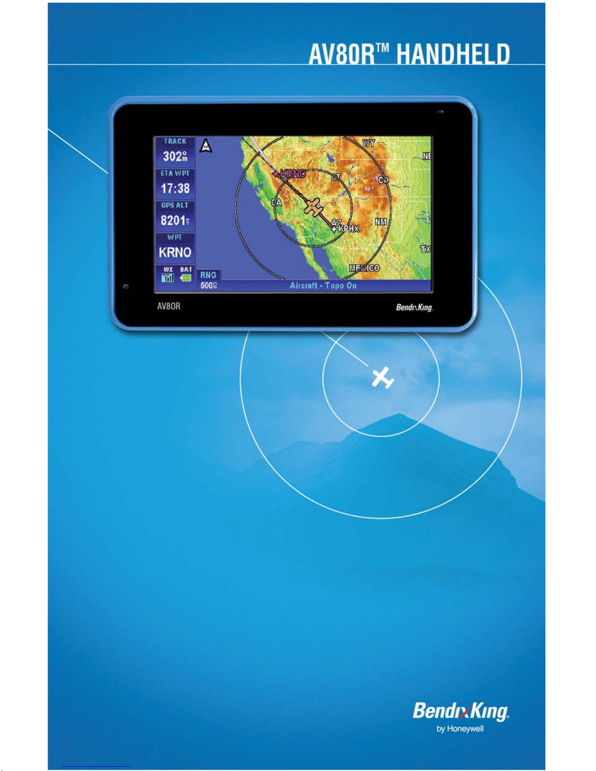
Thank you for choosing the Honeywell AV8OR, a Multi-Function
Display (MFD) that integrates GPS, Navigation Database, Graphical
Terrain, and XM Weather into a single, easy to use, portable aviation
device. In addition to the benefits for aviation use, this device also
contains a complete compliment of automotive navigation and multimedia features for use when not in your aircraft. To get the most out
of your new navigation system, read this manual completely to learn
the features for your unit.
Pub. No D200803000008 Page 1-1 Rev 2 Dec 2008.
© Honeywell International Inc. Do not copy without express permission of
Honeywell.

AV8OR User’s Guide Introduction
HONEYWELL CUSTOMER SUPPORT
For more information, including details regarding your warranty, visit
www.bendixking.com/av8or
For technical support of this product please contact your local
Bendix/King Dealer. To locate the Bendix/King Dealer nearest you
visit www.bendixking.com/av8or
For additional support, contact Honeywell Customer & Product
Support: at:
US & Canada: 1-877-712-2386
All other countries: 1-913-712-2613
Fax: 1-913-712-5697
.
.
Pub. No D200803000008 Page 1-2 Rev 2 Dec 2008.
© Honeywell International Inc. Do not copy without express permission of
Honeywell.

AV8OR User’s Guide Introduction
HONEYWELL AEROSPACE TECHNICAL
PUBLICATIONS
If you have access to the Internet, go to the Honeywell Online
Technical Publications Web site at
https://portal.honeywell.com/wps/portal/aero
• Download or see publications online
• Make an order for a publication
• Tell Honeywell of a possible data error in a publication.
If you do not have access to the Honeywell Online Technical
Publications web site and need techni cal publications information:
• Send an e-mail message to the complete customer care
to:
center at:
• Send a fax or speak to a person at the Customer and
Product Support contact numbers
cas-publications-distribution@honeywell.com
Pub. No D200803000008 Page 1-3 Rev 2 Dec 2008.
© Honeywell International Inc. Do not copy without express permission of
Honeywell.

AV8OR User’s Guide Introduction
This Page
Intentionally Left Blank
• .
Pub. No D200803000008 Page 1-4 Rev 2 Dec 2008.
© Honeywell International Inc. Do not copy without express permission of
Honeywell.

AV8OR User’s Guide Getting Started
2. GETTING STARTED
UNIT OVERVIEW
DISPLAYS AND CONTROLS
The AV8OR has the displays and controls that follow as shown
in Figure 2-1:
Pub. No D200803000008 Page 2-1 Rev 2 Dec 2008.
© Honeywell International Inc. Do not copy without express permission of
Figure 2-1: AV8OR Controls
Honeywell.

AV8OR User’s Guide Getting Started
Table 2-1 Displays and Controls
FIG
NO
DISPLAY OR
CONTROL
DESCRIPTION
1 Touch screen 4.3 inch TFT touch screen.
The resolution is 480 x 272
pixels.
2 POWER key The POWER key is used to
turn the unit on and off and
also can put the unit into
Sleep mode and wake the unit
from Sleep mode.
3 MENU key The MENU key returns the
user to the main menu from
any program in the unit.
4 LED charging status
indicator
Shows the status of the
charging system while the unit
is being charged.
5 SD slot and SD card The SD slot holds a SD card
which contains the aviation
and automotive navigation
software.
6 LOCK tab The LOCK tab disables all
controls and stops the touch
screen from responding to
taps.
7 6 VDC power
connector
This connector lets the unit
receive power from an AC or
an automotive DC.
8 Microphone The microphone is used for
Bluetooth connections to cell
phones.
9 USB/Serial port This is used for a standard
USB connection to a PC to
download movies, pictures, Ebooks and new updates to the
navigational software. Also
used for a RS 232 connection
Pub. No D200803000008 Page 2-2 Rev 2 Dec 2008.
© Honeywell International Inc. Do not copy without express permission of
Honeywell.

AV8OR User’s Guide Getting Started
k
r
FIG
NO
DISPLAY OR
CONTROL
DESCRIPTION
to external hardware with an
optional cable.
10 AV-IN port Future expansion
11 Headset jac
The headset jack accepts a
standard headphone miniature
stereo adapter so the user can
listen to music or movies from
the unit.
12 Volume control knob The volume control controls
the volume of the sound
through the rear speaker or
the Headset jack if a headset
is plugged in.
13 External GPS antenna
jack
The remote GPS antenna jack
allows the user to plug in the
remote GPS antenna that is
supplied with the unit for
better satellite reception.
14 Stylus The stylus allows the user to
precisely tap the touch screen.
15 Removable battery
cover
A replaceable battery is
included with the unit. An
optional battery with a longer
life is also available. The serial
number for the unit is located
on the case under the battery.
16 Internal speake
AV8OR has an Internal
speaker for music, movies,
routing instructions
17 Reset button The reset button reboots the
AV8OR unit.
Pub. No D200803000008 Page 2-3 Rev 2 Dec 2008.
© Honeywell International Inc. Do not copy without express permission of
Honeywell.

AV8OR User’s Guide Getting Started
r
–
SUPPLIED EQUIPMENT
The AV8OR comes preloaded with either USA or European Maps:
Table 2-2 AV8OR Maps
INCLUDED DATABASE
AV8OR SYSTEM PART
NUMBER
066-01207-0001 USA Maps 071-00261-0101
066-01207-0002 European Maps 071-00261-0102
The AV8OR comes with the standard equipment that follows:
Table 2-3 Standard Equipment
DATABASE
( ON SD CARD)
HONEYWELL
PART NUMBER
ITEM PART NUMBER DESCRIPTION
1 066-01207-0099 GPS Base Display Unit, with 800
mAh Battery and battery mounting
bracket
2 005-03702-0002 12-28 VDC Adapto
3 005-03702-0003 120/220 VAC Adapter (with electrical
plug)
4 005-03702-0004 PC/USB Cable
5 005-03702-0005 Carrying Bag
6 005-03702-0006 Remote GPS Antenna
7 005-03702-0007 Aviation Mount
8 005-03702-0009 Automotive Windshield Mount
9 005-03702-0010 Earphone
10 005-03702-0012 CD
User manual
11 005-03702-0013 Quick Reference Guide
OPTIONAL EQUIPMENT
The following accessories are available for the AV8OR:
Pub. No D200803000008 Page 2-4 Rev 2 Dec 2008.
© Honeywell International Inc. Do not copy without express permission of
Honeywell.

AV8OR User’s Guide Getting Started
Table 2-4 Optional Equipment
ITEM PART NUMBER DESCRIPTION
1 005-03702-0014 1600,mAh Battery, (with mounting
bracket)
2 005-03702-0008 Automotive Dashboard Mount
3 005-03702-0017 RS232 Cable
Note: The list of optional equipment may change in the future. For
the latest list of options please visit the www.bendixking.com/av8or
website.
CHARGING THE INTERNAL BATTERY
Before using this unit for the first time or when replacing the internal
battery with a new battery, the internal battery in the AV8OR must be
charged.
Find the power connector (7) on the right side of the unit. Refer
to Figure 2-1.
Re
charge the unit by either using the DC power adapter or the
120/220V AC adapter.
The LED charging indicator (4) on the unit shows a yellow light while
the unit is charging.
Figure 2-2: Charging with AV8OR turned off
When the unit is completely charged, the yellow light changes to a
green light. If the unit is turned on while charging, the charging
Pub. No D200803000008 Page 2-5 Rev 2 Dec 2008.
© Honeywell International Inc. Do not copy without express permission of
Honeywell.

AV8OR User’s Guide Getting Started
animation in the top right portion of the screen also displays a green
battery with full bars.
Note: Battery recycling is encouraged. When replacing the battery,
dispose the old battery in accordance with Local and National
Disposal Regulations.
Figure 2-3: Charge is completed
USING AV8OR
This section explains how to enter and select information with the
AV8OR.
Understanding Terms
The AV8OR unit is designed to allow quick, convenient selection of
navigation options and data entry. As you progress through this
user’s manual, you are directed to tap a specific soft key or highlight
a field on the screen. In order to highlight a field, just touch the field
on the screen.
• Touch or Tap: Use your finger or the AV8OR stylus to touch the
screen on the soft key and remo ve it quickly
• Double tap: Use your finger or the stylus to touch the screen
twice on a field. The double tap is used to open a menu
selection box.
Pub. No D200803000008 Page 2-6 Rev 2 Dec 2008.
© Honeywell International Inc. Do not copy without express permission of
Honeywell.

AV8OR User’s Guide Getting Started
• Pan: Touch the screen and move your finger or stylus across
the screen while continuing to touch the screen. This allows you
to scroll the map and change settings.
• Highlight: Touch on the screen to select the desired individual
fields. Moving the highlight to a desired location allows the user
to make a selection, begin data entry, or scroll through a list.
• Field: The location on a page where data or an option can be
entered and shown.
• Scroll Bar: When viewing a list of items that is too long to show
on the screen, a scroll bar appears along the right side of the list.
To scroll through a list, hold your finger or stylus on the scroll bar
and move your finger or stylus up or down and the list of items
will move up or down too.
TURNING AV8OR ON/OFF
The first time your new AV8OR is turned on, the GPS receiver must
collect satellite data and establish its present location. Before you
turn on the unit, make sure that it has a clear and unobstructed view
of the sky to receive satellite signals.
1. Ensure that the “Lock” switch is unlocked.
2. Hold the Power down soft Key until the blue screen shows.
Figure 2-4: AV8OR Power Up
3. To turn off the AV8OR, press and hold the Power soft Key until
POWER OFF screen shows.
Pub. No D200803000008 Page 2-7 Rev 2 Dec 2008.
© Honeywell International Inc. Do not copy without express permission of
Honeywell.

AV8OR User’s Guide Getting Started
Figure 2-5: AV8OR Power off
AV8OR Sleep Mode
AV8OR can be put into sleep mode as shown in Figure 2-6. AV8OR,
while in
sleep mode, continues to run in a low power mode.
Figure 2-6: AV8OR Sleep Mode
Turn Sleep Mode On and Off
1. To put the unit in Sleep mode, press and quickly release the
Power soft Key until Sleeping shows on the screen for a moment,
then the screen goes blank.
2. To wake up the unit, press and quickly release the Power soft
Key.
MAIN MENU
After the logo startup page shows, the MAIN MENU is displayed.
Pub. No D200803000008 Page 2-8 Rev 2 Dec 2008.
© Honeywell International Inc. Do not copy without express permission of
Honeywell.

AV8OR User’s Guide Getting Started
Figure 2-7: Main Menu
GETTING SATELLITE SIGNALS
When the AV8OR is turned on, it automatically begins to search for
satellite signals. This process can take a few minutes. Be sure the
device has a clear and unobstructed vie w of the sky.
View GPS status from Settings
You can monitor GPS status by tapping the Settings soft key on the
Main Menu page (refer to Figure 2-7), and tapping on the GPS
Status soft key (refer to Figure 2-8).
Figure 2-8: Settings Page
The GPS Status page provides a visual reference of satellite
acquisition, receiver status, current position and a reset mechanism.
Pub. No D200803000008 Page 2-9 Rev 2 Dec 2008.
© Honeywell International Inc. Do not copy without express permission of
Honeywell.

AV8OR User’s Guide Getting Started
GPS SIGNAL STRENGTH
The GPS Signal Strength page is the default page for GPS Status.
As the receiver locks onto satellites, a bar appears for each satellite.
The bar shows the signal strength for each satellite. The bar
changes color from grey to blue when the satellite is locked.
Figure 2-9: GPS Signal Strength Page – Locked and Unlocked
CURRENT POSITION
Tapping this soft key displays the longitude, latitude, altitude (ALT)
and UTC time information for the current position when the device
has acquired a GPS satellite lock.
Pub. No D200803000008 Page 2-10 Rev 2 Dec 2008.
© Honeywell International Inc. Do not copy without express permission of
Honeywell.

AV8OR User’s Guide Getting Started
Figure 2-10: GPS Information of Current position
GPS DATA FLOW
Tapping this soft key shows the GPS national marine electronics
association (NMEA) data in real-time.
SATELLITE ACQUISITION RESET
Tapping this soft key causes the GPS engine to reset. If the unit has
difficulty acquiring satellites, tapping the GPS reset soft key will clear
the GPS engine memory.
Pub. No D200803000008 Page 2-11 Rev 2 Dec 2008.
© Honeywell International Inc. Do not copy without express permission of
Figure 2-11: GPS Data flow
Honeywell.

AV8OR User’s Guide Getting Started
Figure 2-12: GPS Reset
Tap the
soft key to return to the Settings page.
Pub. No D200803000008 Page 2-12 Rev 2 Dec 2008.
© Honeywell International Inc. Do not copy without express permission of
Honeywell.

AV8OR User’s Guide Aviation Mode Operation
Basic Operation
3. AVIATION MODE OPERATION
BASIC OPERATION
This section introduces how to start the aviation mode navigation,
and what the status of the program is during the initialization process.
AVIATION MODE
On the Main Menu page, tap the icon to start the
Aviation mode navigation program.
Program Startup
While the Aviation mode is starting, a startup title page is displayed,
as shown in Figure 3-1.
A self-test status window is displayed under the title box. The selftest checks to make sure the internal navigation, cartography and
terrain databases are correct. While the self-test is checking these
databases, the window header SELF TEST IN PROGRESS is
displayed in yellow.
A green check mark is placed to the right of each test item as it is
checked.
Pub. No D200803000008 Page 3-1 Rev 2 Dec 2008.
© Honeywell International Inc. Do not copy without express permission of
Figure 3-1: Initial Title Page
Honeywell.

AV8OR User’s Guide Aviation Mode Operation
Basic Operation
If the initial self-test fails, the unit is unable to continue operating
safely. A red
is displayed in place of the check mark and the first
soft key changes to HELP, as shown in Figure 3-2.
Figure 3-2: Self Test Failed
When the HELP soft key is tapped, a caution message is displayed
as shown in Figure 3-3.
Figure 3-3: Self Test Failed Caution
The unit should be turned off and then turned back on. If AV8OR still
fails the self-test, please contact customer support.
If the self-test finishes successfully, the self-test window header
changes to SELF TEST COMPLETED in green, as shown in Figure
3-4.
Pub. No D200803000008 Page 3-2 Rev 2 Dec 2008.
© Honeywell International Inc. Do not copy without express permission of
Honeywell.

AV8OR User’s Guide Aviation Mode Operation
Basic Operation
Figure 3-4: SELF TEST COMPLETED Page
The SELF TEST COMPLETED page shows for 2 seconds then the
final title page is displayed as shown in Figure 3-5.
The final title page shows the expiration date of the current
database. Use the AV8OR as an aid to situational awareness only
when the database is current.
For additional information on the current software and database
versions, please go to the System Setup page and tap on the Status
Page soft key to bring up the System Status Menu. Highlight the
Software and Database Versions and tap the Select soft key to
show the current software and software versions.
Pub. No D200803000008 Page 3-3 Rev 2 Dec 2008.
© Honeywell International Inc. Do not copy without express permission of
Figure 3-5: Final Title Page
Honeywell.

AV8OR User’s Guide Aviation Mode Operation
Basic Operation
The user can browse the Bendix/King web page at
http://www.bendixking.com/av8or
to see if a newer version of the
software or database is available.
If the OK soft key is pushed to acknowledge the Jeppesen database,
the Aviation Map page is displayed, as shown in Figure 3-7.
If the DEMO MODE
soft key is tapped, then AV8OR will enter a
simulation mode.
Demo Mode
Demo Mode lets the user become familiar with handling the AV8OR
system on the ground by running in a simulation mode. When the
AV8OR is in Demo Mode, it performs the same as when it is
receiving valid sensor signals to use the various functions. Demo
Mode can only be activated on the final title page during startup, as
shown in Figure 3-5. After tapping the DEMO MODE sof
simulator shows a caution page which must be acknowledged before
continuing.
t key, the
Tap the OK soft key to acknowledge the caution and then the Map
page is displayed.
Pub. No D200803000008 Page 3-4 Rev 2 Dec 2008.
© Honeywell International Inc. Do not copy without express permission of
Figure 3-6: Demo Mode
Honeywell.

AV8OR User’s Guide Aviation Mode Operation
Basic Operation
Figure 3-7: Map Page
Aviation Main Menu Page
Tap on the MAIN MENU soft key on the Map page to display the
Aviation Main Menu Page.
An example of each function in Aviation Mode appears below. Each
function has a specific use and is discussed later in this guide. The
following figures are each of the function’s first pages.
Map: Tap on the soft key on the Aviation Main Menu
•
to return to the Moving Map page. The Map mode is the primary
mode of the system. Refer to the VFR Moving Map Function on
page 3-10 for a detailed explanation of the MAP mode.
Pub. No D200803000008 Page 3-5 Rev 2 Dec 2008.
© Honeywell International Inc. Do not copy without express permission of
Figure 3-8: Main Menu Page
Honeywell.

AV8OR User’s Guide Aviation Mode Operation
Basic Operation
• Flight Plans: Tap on the soft key on the Aviation
Main Menu to show the Flight Plan Index page. The Flight Plan
Index page allows user Waypoints (WPT) and flight plans be
edited and/or created. Refer to the Flight Plan Function section
on pag
e 3-54 for a detailed explanation of the use of flight plan
s.
Figure 3-9: Flight Plan – Flight Plan Index Page
Messages: Tap on the soft key on the Aviation Main
•
Menu to show the Messages page. Refer to the Messages
Function section for a detailed explanation of the Message
function.
Pub. No D200803000008 Page 3-6 Rev 2 Dec 2008.
© Honeywell International Inc. Do not copy without express permission of
Honeywell.

AV8OR User’s Guide Aviation Mode Operation
Basic Operation
Figure 3-10: Messages – Messages Info Page
•
Weather: Tap on the soft key on the Aviation Main
Menu to show the Weather page (if weather is enabled in Device
Setup). The AV8OR system connects with a Bendix/King KDR610 XM receiver or a WxWorx XM receiver through a Bluetooth
or RS 232 interface to receive weather data from the XM
Satellite Radio network. Refer to the Weather Function section
on page 3-78 for a detailed explanation of the Weather function.
Refer to the Connection to An External Weather Source section
in the Appen
onnect the AV8OR to an XM receiver.
c
dix on page 7-9 for a detailed explanation on how to
Figure 3-11: Weather – Weather Map Page
Pub. No D200803000008 Page 3-7 Rev 2 Dec 2008.
© Honeywell International Inc. Do not copy without express permission of
Honeywell.

AV8OR User’s Guide Aviation Mode Operation
Basic Operation
• Traffic: Tap on the soft key on the Aviation Main
Menu to show the Traffic page. The AV8OR system connects
through a RS-232 interface to devices such as the Zaon XRX
traffic receiver. Refer to the Traffic Function section on page 3102 for a detailed explanation of the Traffic function. Refer to
the Connection to An External Traffic Source section on page 717 in the APPENDIX for a detailed explanation on how to
connect the AV8OR to a Traffic receiver.
Figure 3-12: Traffic Main Page
• Settings: Tap on the soft key on the Aviation Main
Menu to show the Settings page. Use the System Setup Menu to
setup map, navigation, data fields, flight plan and other display
preferences. Refer to the System Setup Function section on
page 3-113 for a detailed explanatio
n of the system setup
function.
Pub. No D200803000008 Page 3-8 Rev 2 Dec 2008.
© Honeywell International Inc. Do not copy without express permission of
Honeywell.

AV8OR User’s Guide Aviation Mode Operation
Basic Operation
Figure 3-13: System Setup – System Setup Menu page
Exit: Tap on the soft key on the Aviation Main Menu to
•
exit back to the Main Menu.
Pub. No D200803000008 Page 3-9 Rev 2 Dec 2008.
© Honeywell International Inc. Do not copy without express permission of
Honeywell.

AV8OR User’s Guide Aviation Mode Operation
VFR Moving Map Function
VFR MOVING MAP FUNCTION
The AV8OR features a real-time moving map that can do much more
than just plot your course. The core capability of AV8OR MAP mode
function is its intuitive mapping and navigation function, which is
capable of displaying highly detailed, vectored (point and line) maps.
This detailed vector data includes road over flown data, street
address data, airspace boundaries, airports, Navigational Aid
(NAVAID)s, lakes, rivers, coastlines, cities, highways and terrain
elevation data used to help situational awareness.
MAIN MAP DISPLAY WINDOW
On the Aviation Main Menu, tap on the soft key to enter the
Main Map page, as shown in Figure 3-14.
Figure 3-14: Main Map Display Page
• Data field information (1): The data field information is
displayed along the left side of the screen. For more information
about the data field window configuration please refer to Data
Fields in the next section.
• The ZOOM IN (2)
the map.
Pub. No D200803000008 Page 3-10 Rev 2 Dec 2008.
© Honeywell International Inc. Do not copy without express permission of
icon decreases the displayed range of
Honeywell.

AV8OR User’s Guide Aviation Mode Operation
VFR Moving Map Function
• North Pointer (3): In the upper left corner of the Map display is
a North pointer. The pointer has a triangle shape
. The north
pointer always points north to help orient the map view. Double
tapping on the north pointer toggles the map orientation between
North Up and the Track Up mode.
• Map Page (4): The map page is the main page for Go Fly
aviation mode. The map page shows the aircraft position on the
map.
• Aircraft Symbol (5): A Fixed wing
or Rotary wing
aircraft symbol is displayed in the center of the screen that
represents the actual position of the aircraft. The aircraft symbol
points in the direction of the GPS track based on a valid GPS
position fix.
• If Rotary Wing is selected as aircraft type, and AV8OR
loses a valid GPS position fix, the aircraft symbol is
removed from the screen.
• If Fixed Wing is selected as the aircraft type, and the
aircraft stops, the aircraft symbol stays on the screen
and point in the direction of the last known GPS track.
When the GPS speed is greater than 3 kts, the aircraft
symbol follows the GPS track as the heading source.
The symbol is changed in the System Setup – General
System Setup page.
• Menu Soft keys (6): The menu soft keys are displayed on the
right side of the screen. They allow the user to navigate through
the menu directory. The soft keys are shown initially when the
Map page is first displayed. After a configurable period of time,
the soft keys are removed from the Map page. Tapping on the
Map page causes the menu soft keys to display again. The
MAIN MENU soft key returns to the Aviation Main Menu page.
• Title Bar (7): The title bar shows the currently selected map
view across the bottom of the Map page.
• The ZOOM OUT (8)
the map.
Pub. No D200803000008 Page 3-11 Rev 2 Dec 2008.
© Honeywell International Inc. Do not copy without express permission of
icon increases the displayed range of
Honeywell.

AV8OR User’s Guide Aviation Mode Operation
VFR Moving Map Function
• Map Range (9): The current range (labeled RNG ) is
displayed in the range tag window in the lower left corner of the
display. The range distance unit (nautical miles, statute miles or
kilometers) is configured in the System Setup-GENERAL
SYSTEM SETUP page. Range is measured on the map as the
distance from the center of the aircraft symbol to the outer ring
around the aircraft. The inner ring is at one-half the displayed
range value. These rings are turned on or off in System SetupMAP SETUP page.
• Status window (10): When there is a new aircraft status, a
flashing icon is displayed in the status window in the left bottom
of the data window column
. The status window also
shows the battery condition and the status of the XM weather
receiver (if installed) and traffic information (if installed)
. .
Caution: When AV8OR has lost its GPS position fix, a blue “No
position data” caution message is displayed across the screen and
the aircraft symbol is not displayed.
Figure 3-15: Map – No position data CAUTION
If no altitude data is available and the map display option is set
to Relative Terrain Map, then a “No Altitude Available” message
is displayed.
Pub. No D200803000008 Page 3-12 Rev 2 Dec 2008.
© Honeywell International Inc. Do not copy without express permission of
Honeywell.

AV8OR User’s Guide Aviation Mode Operation
VFR Moving Map Function
Figure 3-16: Map – No Altitude Available CAUTION
Image overlays on Map page: The Topo On Map – Overlay Setup
page shows the images that can be overlaid on the Map page, as
shown in the following figure.
Figure 3-17: Topo On Map - Overlay Setup
• Flight Plan: When there is an active flight plan, the legs and
turning points of the flight plan are shown (Including Direct-To).
• Flight Log Trail: Flight log points are plotted when the flight log
overlay has been enabled for the current map scale.
• Metar: If a meteorological aviation report (METAR) is available,
the METAR icon shows on the map. Tap on the METAR icon to
show the text METAR page.
• TFR: If a TFR is available, a yellow and black dashed TFR
boundary is displayed on the map as shown in the figure below.
Pub. No D200803000008 Page 3-13 Rev 2 Dec 2008.
© Honeywell International Inc. Do not copy without express permission of
Honeywell.

AV8OR User’s Guide Aviation Mode Operation
VFR Moving Map Function
Figure 3-18: TFR Overlay
Tap on the TFR boundary to show the TFR Pop-UP window.
Figure 3-19: TFR Overlay - Popup
Tap on the MORE INFO soft key to show the Temporary Flight
Restriction window.
Pub. No D200803000008 Page 3-14 Rev 2 Dec 2008.
© Honeywell International Inc. Do not copy without express permission of
Honeywell.

AV8OR User’s Guide Aviation Mode Operation
VFR Moving Map Function
Figure 3-20: TFR Overlay - MORE INFO
• Lightning: A lightning strike icon shows in areas where lightning
occurs as shown in the following figure.
Figure 3-21: Lightning Strikes on Map Page
A Lightning strike icon may be caused by a single or multiple
strikes in the same area.
Each strike is less than 7 minutes old when it is initially displayed
on the Map page. Each strike is displayed for 20 minutes. A
lightning strike can remain on the Map page for up to 27 minutes
total.
Pub. No D200803000008 Page 3-15 Rev 2 Dec 2008.
© Honeywell International Inc. Do not copy without express permission of
Honeywell.

AV8OR User’s Guide Aviation Mode Operation
VFR Moving Map Function
CAUTION
The lightning strikes and displayed weather are for
informational purposes only. Weather information from the
XM receiver is not real time and the displayed weather images
should not be used for tactical flying.
• Map page Pointer/Non-Pointer:
The Non-pointer MAP mode screen is displayed showing the
aircraft’s current position on the map using the aircraft symbol in the
center of the screen, if valid GPS signals are available.
Figure 3-22: Map – Non-pointer Map mode
If the soft keys have been hidden, touching anywhere on the screen
in the Main Map Window, will activate a black arrow pointer and the
CLEAR PTR and PTR MENU soft keys will be shown. The pointer
follows the finger or stylus around the screen until the finger or stylus
is lifted from the screen. The pointer can be moved in any direction
to interrogate WPTs or specific map features, such as: airports,
airspace, user defined WPTs and so on. While the pointer is active
the map stops moving to permit easier pointer access to objects, and
the aircraft moves over the map.
Pub. No D200803000008 Page 3-16 Rev 2 Dec 2008.
© Honeywell International Inc. Do not copy without express permission of
Honeywell.
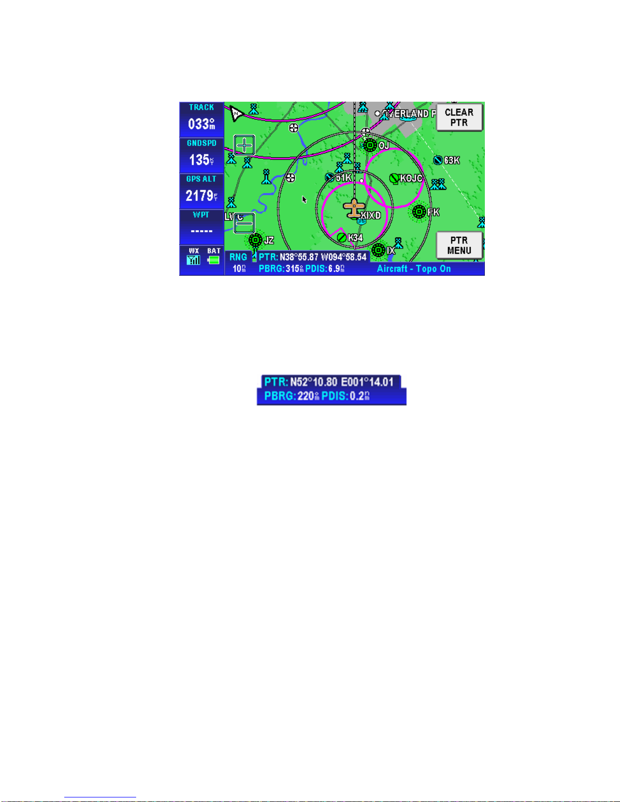
AV8OR User’s Guide Aviation Mode Operation
VFR Moving Map Function
Figure 3-23: Map – Pointer Map mode
In Pointer Map mode, the pointer tag window displays the pointer
position in the currently selected coordinate system. Below the
pointer tag window, the title window component displays the bearing
and distance of the pointer relative to the aircraft’s position.
Figure 3-24: Map – Pointer Tag Window / Title Window
The pointer is removed from the screen after 30 seconds of no
further input (touching and dragging of the pointer).
• Auto-Hide Soft keys: When the map mode is displayed without
touching any control, the on-screen soft key labels are removed
from the screen after a period of time that is configurable, as
shown in Figure 3-25. The default time is 30 seconds.
Pub. No D200803000008 Page 3-17 Rev 2 Dec 2008.
© Honeywell International Inc. Do not copy without express permission of
Honeywell.

AV8OR User’s Guide Aviation Mode Operation
VFR Moving Map Function
Figure 3-25: Map – Without soft keys
For configuration of the Auto-Hide Soft keys, please refer to
the General System Setup page in the System Setup section.
The lab
els are redisplayed when the user touches the screen. This
feature maximizes the visible area for mapping. This feature can be
disabled by setting the Auto-Hide Keys on the Map Mode Page to
OFF in the General System Setup page (Refer to the
General
System Setup section on page 3-114).
Data Fields
Up to four data windows can show at a time on the left side of the
map page. Up to 9 data windows can be configured for display. The
five data windows that do not show on the page are displayed by
dragging the data windows up or down to show the data fields that
are off screen.
Data fields are selected in the System Setup Menu, Refer to
Data Field Setup section on page 3-125.
the
The Data Fields that follow can be selected for display on the map
page.
Altitude Data Field
The Altitude Data Field displays the highest priority
enabled GPS altitude source.
Pub. No D200803000008 Page 3-18 Rev 2 Dec 2008.
© Honeywell International Inc. Do not copy without express permission of
Honeywell.

AV8OR User’s Guide Aviation Mode Operation
VFR Moving Map Function
Bearing Data Field
The Bearing Data Field displays the bearing of the
current destination WPT for the aircraft position in degrees relative to
magnetic north.
Course Deviation Indicator (CDI) Data Field
The Course Deviation Indicator Data Field displays the
perpendicular distance from the aircraft position to the desired track.
The triangle in the center displays whether the aircraft is going TO or
FROM the destination WPT. If the triangle points upwards, the
aircraft is going TO the destination. If the triangle points downwards,
the aircraft is going FROM the destination.
The table below displays the full scale limits for the CDI.
Table 3-1 Course Deviation Limits
Units Available CDI limits
Nautical miles 0.3 nm, 1.0 nm and 5.0 nm
Statute miles 0.4 sm, 1.0 sm and 5.0 sm
Kilometers 0.6 km, 2.0 km and 10.0 km
Departure Time Data Field
The departure time window displays the departure time
when the ground speed of the aircraft is 20 knots or higher. The time
is displayed in HH:MM format. The time is dashed if there is no
departure time available.
Distance to Waypoint Data Field
The distance to waypoint data window displays the
distance from the aircraft to the destination waypoint. The distance is
displayed in the currently selected units for distance.
Pub. No D200803000008 Page 3-19 Rev 2 Dec 2008.
© Honeywell International Inc. Do not copy without express permission of
Honeywell.
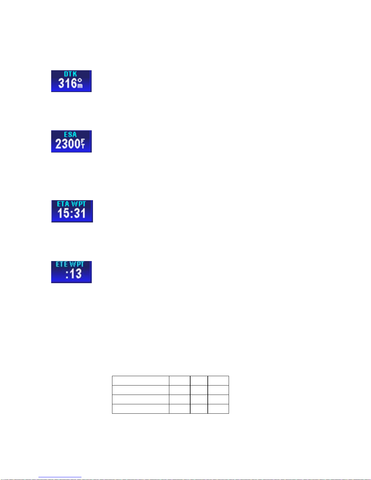
AV8OR User’s Guide Aviation Mode Operation
VFR Moving Map Function
Desired Track Data Field
The desired track data window displays the magnetic
angle from the start waypoint to the destination waypoint as an
integer value
En-Route Safe Altitude Data Field
The en-route safe altitude data window displays the
highest “minimum off-route altitude” along the track line between the
start and destination waypoints. The ESA is displayed in the
currently selected altitude units.
Estimated Time of Arrival Data Field
The estimated time of arrival data window displays the
calculated arrival time calculated as the distance to the destination
waypoint, divided by the ground speed, plus the current time.
Estimated Time En-Route Data Field
The estimated time en-route data window displays the
calculated time en route as the distance to the destination waypoint,
divided by the ground speed. If the ETE is greater than 10 minutes
then the format is HH:MM. If HH is less than 10 then no leading
zeroes are displayed. Otherwise the format is MM:SS, with leading
zeroes displayed. If the ETE is invalid or greater than 24 hours then
“--:--“ is displayed.
Examples are shown in the following table:
Table 3-2 Calculated Time En Route
1hr 55 min 1 : 55
1min:55 sec 01 : 55
24 min : 24
35 sec 00 : 35
Pub. No D200803000008 Page 3-20 Rev 2 Dec 2008.
© Honeywell International Inc. Do not copy without express permission of
Honeywell.

AV8OR User’s Guide Aviation Mode Operation
VFR Moving Map Function
Flight Time Data Field
The flight time data window displays the current flight
duration in HH:MM format. The flight timer displays the current time
in flight or, if the flight has ended, the duration of the flight just ended.
The flight timer begins counting when the ground speed exceeds 20
knots. The flight timer continues until the unit shuts down, or until the
ground speed has been below 3 knots for 5 minutes. If the ground
speed exceeds 20 knots after the flight time had previously stopped
then the flight time continues from the previous flight time.
Groundspeed Data Field
The ground speed data window displays the current
aircraft ground speed in the configured units.
Minimum Safe Altitude Data Field
The minimum safe altitude data window displays the
minimum off-route altitude (from the Jeppesen MORA database.) at
the current aircraft position.
The MSA value is displayed in the currently selected units for altitude.
If the position is invalid then the MSA value is displayed as dashes.
Near Position Data Field
The near position data window displays the current
aircraft position relative to a near-by database feature that is
determined by the user configuration.
If the displayed distance to the nearest selected database feature is
less than 0.1, in the currently selected distance units, then the
position is described as ‘AT’ the database feature.
If the distance is 0.1 or more then the compass bearing from the
database feature is also displayed.
Pub. No D200803000008 Page 3-21 Rev 2 Dec 2008.
© Honeywell International Inc. Do not copy without express permission of
Honeywell.

AV8OR User’s Guide Aviation Mode Operation
VFR Moving Map Function
The bearing is one of sixteen compass bearings (e.g. ENE, NE, and
SSW).
The icon, used to display the database item on the map, is displayed
immediately below the ident.
The ident is displayed to the maximum width displayable in the
selected data window size.
Present Position Data Field
The present position data window displays the
coordinates of the aircraft position in the currently selected
coordinate system.
If the present position is unknown then dashes are displayed.
Stop Watch Data Field
The Stop Watch Window displays the current value of
the Stop Watch in MM:SS format.
The time counts up from 00:00 when enabled (started) and the text
color changes to yellow.
The time stops counting when disabled and the text color changes to
white.
The time is displayed as --:-- in white text when the window is first
displayed.
The largest value that can show is 99:59 at which time it rolls over to
00:00.
Time Data Field
The time data window displays the current system time
in the selected time zone.
The selected time zone abbreviation is displayed in the data window
title, after the word TIME.
If the time is unavailable then dashes are displayed.
The table below lists the time zones that are selectable:
Pub. No D200803000008 Page 3-22 Rev 2 Dec 2008.
© Honeywell International Inc. Do not copy without express permission of
Honeywell.

AV8OR User’s Guide Aviation Mode Operation
f
VFR Moving Map Function
Table 3-3 Time Zones
Time Zone
Description O
Abbreviation
LCL Local time –user
configurable offset from
UTC
UTC Universal time 0:00
GST Greenland Standard Time -3:00
GDT Greenland Daylight Saving
Time
ATS Atlantic Standard Time -4:00
ATD Atlantic Daylight Saving
Time
EST Eastern Standard Time -5:00
EDT Eastern Daylight Saving
Time
CST Central Standard Time -6:00
CDT Central Daylight Saving
Time
MST Mountain Standard Time -7:00
MDT Mountain Daylight Saving
Time
PST Pacific Standard Time -8:00
PDT Pacific Daylight Saving
Time
AKS Alaska Standard Time -9:00
AKD Alaska Daylight Saving
Time
HAS Hawaii Standard Time -10:00
HAD Hawaii Daylight Saving
Time
SST Samoa Standard Time -11:00
SDT Samoa Daylight Saving
Time -
Track Angle Error Data Field
fset
from UTC
User
defined
-2:00
-3:00
-4:00
-5:00
-6:00
-7:00
-8:00
-9:00
-10:00
The track angle error data window displays the
difference between the desired track and the current aircraft track
Pub. No D200803000008 Page 3-23 Rev 2 Dec 2008.
© Honeywell International Inc. Do not copy without express permission of
Honeywell.

AV8OR User’s Guide Aviation Mode Operation
VFR Moving Map Function
over ground in integer degrees. An arrow indicates the direction to
steer to reduce the track angle error.
Track Angle Data Field
The track angle data window displays the track angle of
the aircraft over the ground in integer degrees relative to magnetic
north.
Track To Steer Data Field
The track to steer data window displays the calculated
optimum track over ground angle to be flown to achieve the desired
track to the destination waypoint as an integer value relative to
magnetic north.
Traffic Mini-Targets Data Field
The traffic mini-targets data field displays a reduced
representation of the main traffic display within a double height data
field. All of the mini-traffic targets are displayed relative to the nose
of the aircraft. The traffic mini-targets only show when the Map page
is in “Track Up” mode. This prevents confusion between the main
Map page display and the mini targets display.
The traffic mini-targets data field displays targets out to 6 nm (7 sm
or 10 km).
Waypoint Ident Data Field
The waypoint ident data window displays the ident of
the current destination waypoint.
If the waypoint ident is unavailable then dashes are displayed.
The waypoint ident is truncated to fit into the size of the data window.
Cross Track Error Data Field
Pub. No D200803000008 Page 3-24 Rev 2 Dec 2008.
© Honeywell International Inc. Do not copy without express permission of
Honeywell.

AV8OR User’s Guide Aviation Mode Operation
VFR Moving Map Function
The cross track error data window displays the
magnitude of, and direction to steer, to reduce the perpendicular
distance between the aircraft position and the desired track. An
arrow is displayed to the right of the cross track error value indicating
the direction to steer to reduce the cross track error.
VFR MOVING MAP OPERATION
Map Zooming
ZOOM IN or ZOOM OUT changes the current map range to the next
value. Holding either soft key smoothly increments or decrements
(changes the range by 10 percent) through the ranges permitting the
user to stop at almost any range value desired. Pushing the opposite
ZOOM soft key steps the range in the opposite direction. The map
range value will be displayed on the RNG label.
The ZOOM IN and ZOOM OUT soft keys disappear when the
maximum or minimum limit is reached.
When the pilot operates the unit outside of the data base region
contained on the SD card and zooms into a range that requires the
high resolution terrain data, the pilot will see a purple background
screen color and a message stating “Outside Database Region”.
This warning and alert is issued at all zoom levels where the high
resolution terrain data is not available.
Map View
The MAP VIEW soft key allows the user to select the information to
be shown on the map. Tapping the MAP VIEW soft key on the MAIN
MAP DISPLAY window brings up the CHANGE VIEW soft key.
Pub. No D200803000008 Page 3-25 Rev 2 Dec 2008.
© Honeywell International Inc. Do not copy without express permission of
Honeywell.

AV8OR User’s Guide Aviation Mode Operation
VFR Moving Map Function
Figure 3-26: Map – Map View Setup
Tap the SAVE & EXIT soft key to return to the Map page.
Smart Profile
The Smart Profile mode displays the vertical profile of the flight path
along the route of flight above the title bar. A cross section of the
terrain for the flight is shown on the vertical profile. A dashed line is
shown to represent the altitude of the flight path.
If Smart Profile is OFF, tapping the MAP VIEW soft key ,then the
SMART PROFILE soft key toggles Smart Profile to ON. The map
image shrinks 25% to show the SMART PROFILE on the bottom on
the screen.
Figure 3-27: Map - Smart Profile On
If Smart Profile is ON tapping the SMART PROFILE soft key toggles
the Smart Profile mode to OFF.
Pub. No D200803000008 Page 3-26 Rev 2 Dec 2008.
© Honeywell International Inc. Do not copy without express permission of
Honeywell.

AV8OR User’s Guide Aviation Mode Operation
VFR Moving Map Function
Vertical profiles of airspace vertical boundaries and man-made
obstructions are also displayed in the Smart Profile window.
Figure 3-28: Smart Profile - Airspace Vertical Boundaries
Auto Zoom
Tapping the AUTO ZOOM soft key resumes the Auto Zoom mode if
Auto zoom has been set to “Suspended”.
Figure 3-29: Auto Zoom Mode
The Auto Zoom function can be turned on or off or suspended
When flying the last leg of a Flight Plan or when flying a Direct To,
the system automatically zooms to a screen range that keeps the
destination WPT within the display area. The system continues to
zoom in to the lowest zoom level.
Pub. No D200803000008 Page 3-27 Rev 2 Dec 2008.
© Honeywell International Inc. Do not copy without express permission of
Honeywell.

AV8OR User’s Guide Aviation Mode Operation
VFR Moving Map Function
When the lowest zoom has been reached and the aircraft begins to
fly away from the destination WPT, then the system zooms out
automatically to keep the WPT within the display area.
When auto zoom is in operation AUTO (Automatic) is shown in the
RNG (Range) display field. Pushing either the ZOOM IN or ZOOM
OUT soft key cancels the auto zoom capability.
Change View
Tapping the CHANGE VIEW soft key toggles the display through the
different map types. The Map page defaults to Topo On.
• Topo On
Figure 3-30: Map – Topo On
• Relative Terrain
CAUTION
NEVER USE THE TOPOGRAPHIC ELEVATION
DISPLAYED ON THIS EQUIPMENT AS YOUR SOLE
REFERENCE FOR TERRAIN AVOIDANCE.
Pub. No D200803000008 Page 3-28 Rev 2 Dec 2008.
© Honeywell International Inc. Do not copy without express permission of
Honeywell.

AV8OR User’s Guide Aviation Mode Operation
k
VFR Moving Map Function
Figure 3-31: Map – Relative Terrain
• On the Relative Terrain map, the terrain is colored
according to its height relative to the aircraft, as
shown in the following table.
o A 0.5 nm radius circle around each is colored
according to the height of the obstacle relative to the
aircraft, as shown in the following table.
Table 3-4 Relative Terrain
Relative Terrain
Altitude (feet)
Relative
Obstacle
Color Dither
Altitude (feet)
>= +250 >= -250 Red 50%
-250 to +249 -750 to –251 Yellow 50%
-750 to –251 -1250 to –751 Yellow 25%
-1250 to –751 -17500 to –1251 Dark
Green
/Dark
Yellow
-2000 to –1251 < -2000 to -1751 Dark
Green
< -2000 < -2000 Blac
o At ranges of 200 nm and less, areas not covered by
the terrain database are displayed using a 50 % red
dithered pattern.
Pattern
Percent
Filled
50%
100%
100%
Pub. No D200803000008 Page 3-29 Rev 2 Dec 2008.
© Honeywell International Inc. Do not copy without express permission of
Honeywell.

AV8OR User’s Guide Aviation Mode Operation
VFR Moving Map Function
o The Relative Terrain Map is rotated and scaled
consistent with the current map location, orientation
and range.
o When terrain data is scaled for display, the highest
elevation is used for each location to determine its
color.
o The 0.5 nm radius circles around obstacles are
displayed only if their radii after scaling are large
enough to be shown.
o If altitude information is not available then a warning
message is displayed on the map image with the text
“No Altitude Available. Relative Terrain Not Displayed.”
• Topo Off
Figure 3-32: Map – Topo Off
Tapping the MAP SETUP soft key allows the user to configure the
Map Setup options. For more detail information about Map Setup,
refer to the System Setup – Map Setup section.
NEAREST – Select Nearest Destination:
The NEAREST soft key gives access to the Nearest Database
Selection window, as shown in Figure 3-33. The NE
lets the user get information or navigate using a
WPT within the nearest database.
Pub. No D200803000008 Page 3-30 Rev 2 Dec 2008.
© Honeywell International Inc. Do not copy without express permission of
AREST soft key
soft key to any
Honeywell.

AV8OR User’s Guide Aviation Mode Operation
VFR Moving Map Function
Figure 3-33: Map – Nearest Database Selection
Tapping the NEAREST soft key on the Map page shows the
Nearest Database Selection menu. In the menu you can select;
Nearest Airports, Nearest VORs, Nearest User WPTs or Nearest
Towns and Cities as a destination.
The 40 nearest Airports/Helipads, VORs or User Waypoints or a
combination of them that are nearest to the aircraft’s current position
are accessible through the Nearest Database Selection menu.
To select an item as your destination from the Nearest Database
Selection Menu:
Tap the NEAREST soft key in MAP mode.
Select the category (Near Airports, Near VORs, Near User WPTs,
Near Towns and Cities), using the pointer to highlight the selection.
Tap the SELECT soft key to show the list of possible destinations for
the selected category.
Pub. No D200803000008 Page 3-31 Rev 2 Dec 2008.
© Honeywell International Inc. Do not copy without express permission of
Honeywell.

AV8OR User’s Guide Aviation Mode Operation
VFR Moving Map Function
Figure 3-34: Map – Nearest Airport List
The user can select one destination and tap the MORE INFO soft
key to view the detail information, as shown in Figure 3-35. The
ZOOM IN an
d ZOOM OUT soft keys allow the user to change the
airport area map range. Tap the NEXT soft key to display the next
page of airport information.
Figure 3-35: Map – Airport information
For Nearest Airports, tapping the AIRPORT FILTER soft key allows
the user to configure the airport filter by setting the minimum runway
length and surface requirements. The filter will not allow airports
below the minimum requirements to be displayed in the list.
Pub. No D200803000008 Page 3-32 Rev 2 Dec 2008.
© Honeywell International Inc. Do not copy without express permission of
Honeywell.

AV8OR User’s Guide Aviation Mode Operation
VFR Moving Map Function
Figure 3-36: Map - Airport Filter
When the user has selected (highlighted) the nearest point in the
desired destination list, the user taps the
soft key. The system
sets a new course from the aircraft’s present position directly to the
desired nearest point’s position and shows the new Direct-To course
on the map.
To cancel an active Direct-To navigation, tap the soft key, tap the
Clear soft key on the virtual keyboard and then tap the Enter soft
key.
Waypoint Alert
Pub. No D200803000008 Page 3-33 Rev 2 Dec 2008.
© Honeywell International Inc. Do not copy without express permission of
Figure 3-37: Map – Direct-To OFF
Honeywell.

AV8OR User’s Guide Aviation Mode Operation
VFR Moving Map Function
The Waypoint Alert flashes the next desired track (NEXT DTK) when
the estimated time to the next waypoint is about 20 seconds as
shown in the following figure. Turning to establish the NEXT DTK will
aid in intercepting the next leg of the flight plan.
Figure 3-38: Waypoint Alert
Turn Anticipation
When Turn Anticipation is enabled in Navigation Setup, it
provides turn guidance to a new course to intercept the next leg of
the flight plan.
Waypoint Alerting begins when the estimated time to the start of the
turn is about 20 seconds. The Waypoint Alert is annunciated by
flashing the next desired track (NEXT DTK) window as shown in the
figure above.
When the computed turn point is reached TURN TO is displayed as
shown in the following figure.
Pub. No D200803000008 Page 3-34 Rev 2 Dec 2008.
© Honeywell International Inc. Do not copy without express permission of
Honeywell.

AV8OR User’s Guide Aviation Mode Operation
VFR Moving Map Function
Figure 3-39: Turn Anticipation
The required bank angle to follow the arc will normally be between 3°
and 25° depending on the aircraft speed and the amount of course
change.
DIRECT-TO Navigation
Direct-To Navigation lets the user set a course line from his current
position to any other position. Direct-To Navigation can be done with
the methods that follow:
• Create a Direct-To course from the Map.
• Create a Direct-To course from the keyboard entry.
• Re-center the aircraft when Direct-To is already enabled
• Bypass a WPT with a flight plan active
• Enter a new WPT with a flight plan active.
Create a Direct-To course from the Map
Pan and zoom in/out on the map to find the NAVAID point you want
to set a course to. Tap on the NAVAID point to show its name, more
detail information about the NAVAID point is shown by tapping the
MORE INFO soft key, as shown in Figure 3-40.
Pub. No D200803000008 Page 3-35 Rev 2 Dec 2008.
© Honeywell International Inc. Do not copy without express permission of
Honeywell.

AV8OR User’s Guide Aviation Mode Operation
VFR Moving Map Function
Figure 3-40: Map - Select a NAVAID
Tapping the PTR MENU soft key, on the right side of the screen,
shows the soft key.
Figure 3-41: Map - Direct To a NAVAID
Tapping the
soft key causes the system to create a new course
from the aircraft’s present position directly to the selected NAVAID
point. The new course line is colored magenta.
Pub. No D200803000008 Page 3-36 Rev 2 Dec 2008.
© Honeywell International Inc. Do not copy without express permission of
Honeywell.

AV8OR User’s Guide Aviation Mode Operation
VFR Moving Map Function
Figure 3-42: Map - Navigate to a NAVAID point
Create a Direct-To course from the keyboard entry (No
Flight Plan)
Tap the soft key from the Map page to display the virtual
keyboard on the screen as shown in Figure 3-43.
Figure 3-43: Map – Virtual Keyboard
Tap the Esc soft key to return to the Map page.
Tap the Clear soft key to clear the entry you typed in.
The user taps on the keyboard to enter the Ident, name or the
location of the existing NAVAID point. The closest match to the entry
shows on the page as you type in the data. If the closest match is
Pub. No D200803000008 Page 3-37 Rev 2 Dec 2008.
© Honeywell International Inc. Do not copy without express permission of
Honeywell.

AV8OR User’s Guide Aviation Mode Operation
VFR Moving Map Function
correct, tap the Enter soft key to accept without having to finish
typing the complete location.
After the Enter key is tapped, a Waypoint Entry screen shows
detailed information about the entered location.
Figure 3-44: Map – Entered Waypoint Info
Tap the CANCEL soft key to cancel the Direct-To and return to the
virtual keyboard page to enter a different location or to Esc back to
the Map page.
Tap the MORE INFO soft key to see additional information about the
location. If additional pages are available, the NEXT INFO soft key
shows. When finished browsing the additional data, tap the CLEAR
soft key to return to the WayPoint Entry Screen.
Tap the OBS soft key to start an OBS course and show the
magnetic heading from your present position to the WPT
.
Tap the DIRECT TO soft key to accept the entered location. The
system sets a new course from the aircraft’s present position directly
to the entered WPT’s position and shows the new Direct-To course
on the Map.
Pub. No D200803000008 Page 3-38 Rev 2 Dec 2008.
© Honeywell International Inc. Do not copy without express permission of
Honeywell.

AV8OR User’s Guide Aviation Mode Operation
VFR Moving Map Function
Re-center aircraft when Direct-To is already enabled
When flying on a course using the Direct-To function, if the aircraft
gets away from the course line on the map, the pilot can easily
create a new course line to the destination from the aircraft’s present
position by using the steps that follow:
Tap the
soft key from the Map page to display the virtual
keyboard. The active Direct-To destination will already be filled in on
the keyboard.
Figure 3-45: Re-center aircraft – Step 1
Tap the Enter soft key to use the entered WPT and re-center the
course line from the aircraft’s present position to the destination.
Bypass a WPT with a flight plan active
When a flight plan is active, the pilot may want to bypass one of the
WPTs in the flight plan and go direct to one of the other WPTs. Use
the steps that follow to bypass a WPT.
The active course shows as a magenta line on the Map.
Pub. No D200803000008 Page 3-39 Rev 2 Dec 2008.
© Honeywell International Inc. Do not copy without express permission of
Honeywell.

AV8OR User’s Guide Aviation Mode Operation
VFR Moving Map Function
Figure 3-46: Step 1 Bypass a WPT
Tap on the
soft key to display the Active Flight Plan page.
Figure 3-47: Bypass a WPT - Step 2
Highlight the WPT in the Active Flight Plan you want to go to next.
Pub. No D200803000008 Page 3-40 Rev 2 Dec 2008.
© Honeywell International Inc. Do not copy without express permission of
Honeywell.

AV8OR User’s Guide Aviation Mode Operation
VFR Moving Map Function
Figure 3-48: Bypass a WPT - Step 3
Tap on the
soft key to create a new course from the aircraft’s
present position to the selected WPT.
Figure 3-49: Bypass a Waypoint Step 4
Enter a Direct-To WPT with a flight plan active.
The active course shows as a magenta line on the Map.
Pub. No D200803000008 Page 3-41 Rev 2 Dec 2008.
© Honeywell International Inc. Do not copy without express permission of
Honeywell.

AV8OR User’s Guide Aviation Mode Operation
VFR Moving Map Function
Figure 3-50: Enter a New WPT with Flight Plan Active
Tap on the
soft key to display the Active Flight Plan page.
Figure 3-51: Enter New WPT – Select KEYBD Soft key
Tap on the KEYBD ENTRY soft key to display the virtual keyboard
entry screen with the next WPT entry already entered.
Enter the new WPT you want to go direct to.
Pub. No D200803000008 Page 3-42 Rev 2 Dec 2008.
© Honeywell International Inc. Do not copy without express permission of
Honeywell.

AV8OR User’s Guide Aviation Mode Operation
VFR Moving Map Function
Figure 3-52: Enter New WPT Ident
Tap on the Enter soft key when done and then tap on the OK soft
key to activate the Direct-To WPT. This will suspend the active flight
plan and create a new course from the aircraft present position to the
selected location. The new course shows in a magenta color.
PTR MENU
Create a User Waypoint
When you tap a NAVAID point or any blank place on the map, the
PTR MENU soft key is displayed. Tap the PTR MENU soft key to
show the pointer menu.
Pub. No D200803000008 Page 3-43 Rev 2 Dec 2008.
© Honeywell International Inc. Do not copy without express permission of
Figure 3-53: New Direct-To Active.
Honeywell.

AV8OR User’s Guide Aviation Mode Operation
VFR Moving Map Function
.
Figure 3-54: Map –PTR MENU – Save Waypoint
Choose the Save Waypoint item, and tap the SELECT soft key, a
user defined WPT is created at the point position on the map with
the name USRXXX. Tap on the waypoint to show the User Waypoint
popup window, as shown in the figure below
Figure 3-55: Map – User Defined Waypoint
The User Waypoint popup window lists the waypoint ID and the date
and time the waypoint was created.
Tap on the MORE INFO soft key to display additional information
about the waypoint.
Pub. No D200803000008 Page 3-44 Rev 2 Dec 2008.
© Honeywell International Inc. Do not copy without express permission of
Honeywell.

AV8OR User’s Guide Aviation Mode Operation
VFR Moving Map Function
Figure 3-56: User Waypoint - MORE INFO
Tap the DELETE WPT soft key to delete the waypoint.
Tap the CLEAR soft key to return to the previous menu.
Center the Map around Pointer Position
On the Map page, tap a point on the map to display the PTR MENU
soft key.
Figure 3-57: PTR Menu - Center to Map
Tap on the PTR MENU soft key to show the pointer menu.
Pub. No D200803000008 Page 3-45 Rev 2 Dec 2008.
© Honeywell International Inc. Do not copy without express permission of
Honeywell.

AV8OR User’s Guide Aviation Mode Operation
VFR Moving Map Function
Figure 3-58: Pointer Menu
Choose the Center Map option and tap the SELECT soft key to
center the position of the Map page on the pointer position.
Figure 3-59: Map Centered on Pointer
PTR MENU – DIRECT-TO Navigation
The DIRECT TO shows the course to navigate the aircraft to the
desired WPT directly when the WPT was selected from the pointer
map mode screen. When the user moves the pointer arrow to any
desired map location, the pointer’s position (PTR), bearing (PBRG)
Pub. No D200803000008 Page 3-46 Rev 2 Dec 2008.
© Honeywell International Inc. Do not copy without express permission of
Honeywell.

AV8OR User’s Guide Aviation Mode Operation
VFR Moving Map Function
and distance (PDIS) are shown on two lines at the bottom left of the
screen
To select a user defined point on the map:
If the user taps on a point on the map that is not a NAVAID pointer
stored in database, taps on the PTR MENU soft key and then taps
the
the pointer position on the map and a new course from the aircrafts
present position directly to the selected NAVAID point is created.
The new course line is colored magenta.
soft key, a temporary WPT named USRXXX is created at
Figure 3-60: Map – Navigate to a user defined WPT
PTR MENU – OBS Navigation
To select a NAVAID point on the map:
If the user touches a NAVAID point on the map and taps the PTR
MENU soft key, the OBS soft key will be shown. After the OBS soft
key is tapped, the OBS window shows the magnetic course to the
NAVAID.
Pub. No D200803000008 Page 3-47 Rev 2 Dec 2008.
© Honeywell International Inc. Do not copy without express permission of
Honeywell.

AV8OR User’s Guide Aviation Mode Operation
VFR Moving Map Function
Figure 3-61: OBS Course to NAVAID
To select a user defined point on the map:
If the point the user touches is not a NAVAID point, then after the
OBS soft key is tapped, a temporary WPT is created at that position.
The OBS course ends at that user defined temporary WPT.
To edit the OBS Course Angle, double tap on the OBS Course
Window to open a key pad.
After the OBS point is selected the OBS course selection window is
shown and the DONE,
and CANCEL OBS soft keys are
displayed, as shown in Figure 3-62.
Figure 3-62: Map –OBS Start
Tap the DONE soft key and the adjusted OBS course is activated
and a course is generated to the selected point, as shown in Figu re
3-63.
Pub. No D200803000008 Page 3-48 Rev 2 Dec 2008.
© Honeywell International Inc. Do not copy without express permission of
Honeywell.

AV8OR User’s Guide Aviation Mode Operation
VFR Moving Map Function
Figure 3-63: Map – OBS Navigation
Tap the OBS ADJUST soft key to show the following window.
Figure 3-64: Map – OBS Configuration
Here double tapping on the OBS Course window allows the user to
adjust the OBS course.
The user can fly an OBS course to any selected point even while
flying an active flight plan. This provides the ability to show an
extended runway centerline for any airport or user selected point of
interest.
Cancel the OBS using the
or CANCEL OBS soft keys.
Pub. No D200803000008 Page 3-49 Rev 2 Dec 2008.
© Honeywell International Inc. Do not copy without express permission of
Honeywell.

AV8OR User’s Guide Aviation Mode Operation
VFR Moving Map Function
Center Map
In pointer map mode (User taps on the map and a black pointer is
shown and the PTR MENU soft key is tapped), the CENTER MAP
soft key is shown as an option on the Pointer Menu. Refer to Figure
3-54.
The CENTER MAP option is tapped to center the map on the PTR
position on the map.
Tap on the CLEAR PTR to return clear the PTR position and center
the aircraft on the map. The PTR position will remain centered on the
Map for a period of time and then the Map page changes to show
the aircraft position centered on the Map.
Center To WPT/Center Aircraft
After any kind of navigation was activated, in Non-Pointer mode, the
CENTER TO WPT soft key is shown for the user to view the WPT
position on the map.
The CENTER TO WPT soft key changes to a CENTER AIRCRAFT
soft key after the CENTER TO WPT soft key is tapped.
The CENTER AI RCRAFT soft key is shown for the user to show the
aircraft’s present position on the map.
Figure 3-65: Map – Center to WPT
Pub. No D200803000008 Page 3-50 Rev 2 Dec 2008.
© Honeywell International Inc. Do not copy without express permission of
Honeywell.

AV8OR User’s Guide Aviation Mode Operation
VFR Moving Map Function
Figure 3-66: Map – Center Aircraft
Selectable GPS Data Source
The AV8OR system can receive data from either the internal or an
external GPS Source. When an external source is configured, the
unit uses data from it. Switching to the internal GPS source is
automatic when data from the external source is no longer valid or
available.
AUTONAV
When enabled, AutoNav allows the AV8OR to automatically switch
to the internal GPS source when the external source is unavailable
or has failed.
The AutoNav function is not enabled until both the internal and the
external position source have acquired a valid satellite fix or the Go
Fly program has been running for 4 minutes.
If the external position source is invalid for more than 5 seconds, the
Go Fly program will switch to the internal GPS antenna.
The following sequence of events occurs:
• If the flight plan source is the external GPS, then the flight
plan is captured and cross-referenced to the internal
database.
Pub. No D200803000008 Page 3-51 Rev 2 Dec 2008.
© Honeywell International Inc. Do not copy without express permission of
Honeywell.

AV8OR User’s Guide Aviation Mode Operation
VFR Moving Map Function
• The following warning message is displayed that requires
pilot confirmation.
“The external GPS source is no longer available. The GPS
source has been changed to the internal GPS backup. GPS
limited to VFR use only. PRESS OK TO ACKNOWLEDGE”.
• Touching the OK soft key closes the message window.
• If the external GPS source becomes valid again for a period
of more than 5 seconds, the AutoNav function automatically
switches back to the external GPS source.
• The following warning message window is displayed that
requires pilot confirmation.
“The external GPS source is now available. The GPS source
has been changed to the external GPS source. PRESS OK
TO ACKNOWLEDGE”.
• Tapping the OK soft key closes the message window.
STOP WATCH
Figure 3-67: Stop Watch Data Field
The stopwatch can be started or stopped only when the
data window shows on the Map screen.
When the stopwatch is stopped, double tap the
the timer.
Pub. No D200803000008 Page 3-52 Rev 2 Dec 2008.
© Honeywell International Inc. Do not copy without express permission of
icon to start
Honeywell.

AV8OR User’s Guide Aviation Mode Operation
VFR Moving Map Function
When the stopwatch is running, double tap the icon to stop
the timer. Double tap the
icon to reset it.
When the stopwatch is active, it continues to count even if the
stopwatch data window is not being displayed.
Pub. No D200803000008 Page 3-53 Rev 2 Dec 2008.
© Honeywell International Inc. Do not copy without express permission of
Honeywell.

AV8OR User’s Guide Aviation Mode Operation
Flight Plan Function
FLIGHT PLAN FUNCTION
VFR flight plans can be created in the AV8OR-XP when configured
to use the internal GPS.
Flight plans can also be created on a PC with the Jeppesen
FliteStar© PC application. Refer to the Chapter 7 Appendix section,
for more information on how to import a flight plan.
The FLIGHT PLAN function is selected through the Aviation Main
Menu, as shown in Figure 3-7. Tap on the
icon to open the
Flight Plans Index page.
Figure 3-68: Flight Plan Index Page
Two options are available from the Initial Page, NEW FPLAN and
USER WPTS.
USER WPTS
Tapping the USER WPTS soft key shows the current User defined
WPTs list. Refer to Figure 3-93.
Pub. No D200803000008 Page 3-54 Rev 2 Dec 2008.
© Honeywell International Inc. Do not copy without express permission of
Honeywell.

AV8OR User’s Guide Aviation Mode Operation
Flight Plan Function
Figure 3-69: Flight Plan - User Waypoint List
The user can tap the NEW WPT soft key to define a new WPT. A
maximum of 1000 user WPTs can be created.
The user can also tap the EDIT WPT soft key to edit the selected
WPT’s parameters.
Figure 3-70: Flight Plan – New/Edit User Waypoint
When the user creates a new WPT or edits an existing WPT, the
User Waypoint Edit page is shown. The AV8OR system creates a
default: Ident name, Icon, Position, Comment 1 and Comment 2
parameters for the new WPT. The default Ident name is in the format
USRXXX and the default position is the current aircraft’s position.
In the User Waypoint Edit page the user can edit all these
parameters. Highlight the Ident item, and the CLEAR IDENT soft key
becomes available to clear the current Ident name. Highlight the
Pub. No D200803000008 Page 3-55 Rev 2 Dec 2008.
© Honeywell International Inc. Do not copy without express permission of
Honeywell.

AV8OR User’s Guide Aviation Mode Operation
Flight Plan Function
Comment 1 / Comment 2 items and the CLEAR TEXT soft key
becomes available to clear the comment text.
Tap the RNG&BRG soft key to display the range and bearing
configuration page.
Figure 3-71: Flight Plan – WPT Range and Bearing Config
In the Range and Bearing page the DELETE soft key allows the user
to delete this WPT. The SAVE&EXIT soft key saves all WPT
configurations and exits to the User Waypoint List page (Note: If the
user entered the User Waypoint Edit page from the VFR moving
map page, then this screen will return to the VFR moving map page.)
Tap the USER WPT soft key to return to the User Waypoint Edit
page.
User Airport Entry
If a VFR Airport Icon is selected for the Icon field, a NEXT soft key is
displayed on the screen as shown in the following figure.
Pub. No D200803000008 Page 3-56 Rev 2 Dec 2008.
© Honeywell International Inc. Do not copy without express permission of
Honeywell.
 Loading...