

Beko CWB 9550 X, CWB 9510 X, CWB 6600 X, CWB 6500 X, CWB 9600 X Operating Instructions
GB
COOKER HOOD - User instructions
CZ
ODSAVAČ PAR
DK
EMHÆTTE - Brugervejledning
FIN
LIESITUULETIN – Käyttöohje
GR
ΑΠΟΡΡΟΦΗΤΗΡΑΣ ΣΕ ΕΚ∆ΟΣΗ ΑΠΟΡΡΟΦΗΣΗΣ – Εγχειρίδιο χρήσησ
H
ELSZÍVÓ KÜRTŐ – Használati utasítás
N
AVTREKKSKAPPE – Bruksanvisning
PL
OKAP ZASYSAJĄCY - instrukcja obsługi
R
HOTĂ ASPIRANTĂ – Manual de utilizare
RUS
ВЫТЯЖНОЙ КОЛПАК - Руководство пользователя
S
SPISKÅPA – Bruksanvisning
- návod k použití

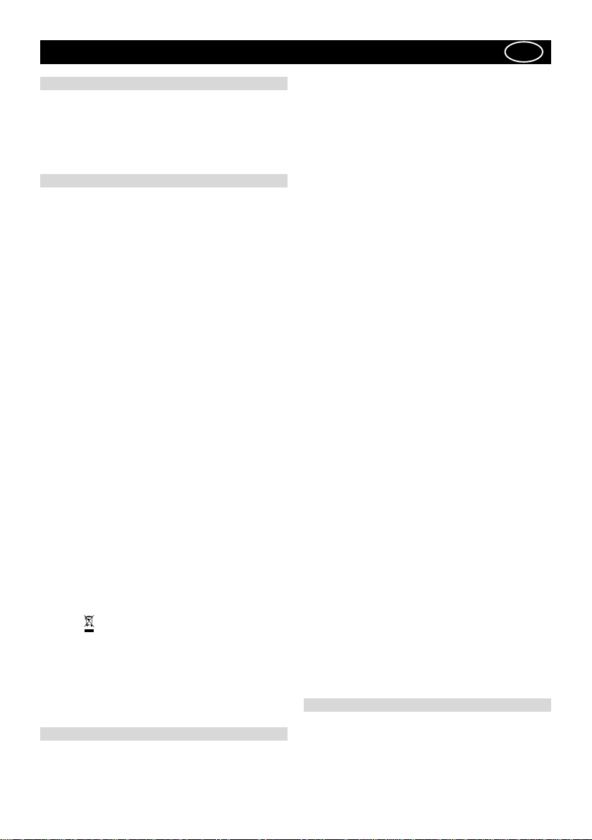
ABC
M
Fig.1
20
max 90 cm
Fig.2
A
235
A
A
Fig.3
B
A
C
A
Fig.4
B
Fig.5
- 3 -
A
Fig.6
Fig.7
A
B
Fig.8 Fig.9
A
A
C
B
G
E
D
D
F
E
A
C
B
A
B
D
C
F
E
A
B
A
B
Fig.10 Fig.11
D
C
F
E
B
C
D
E

ENGLISH
GB
GENERAL
Carefully read the following important information regarding
installation safety and maintenance. Keep this information
booklet accessible for further consultations. The
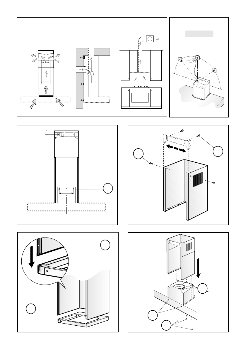
appliance has been designed for use in the ducting version
(air exhaust to the outside – Fig.1B), filtering version (air
circulation on the inside – Fig.1A) or with external motor
(Fig.1C).
SAFETY PRECAUTION
1. Take care when the cooker hood is operating
simultaneously with an open fireplace or burner that
depend on the air in the environment and are supplied by
other than electrical energy, as the cooker hood removes
the air from the environment which a burner or fireplace
need for combustion. The negative pressure in the
environment must not exceed 4Pa (4x10⁻⁵ bar). Provide
adequate ventilation in the environment for a safe
operation of the cooker hood. Follow the local laws
applicable for external air evacuation.
Before connecting the model to the electricity network:
- control the data plate (positioned inside the appliance)
to ascertain that the voltage and power correspond to
the network and the socket is suitable. If in doubt ask a
qualified electrician.
- If the power supply cable is damaged, it must be replaced
with another cable or a special assembly, which may be
obtained direct from the manufacturer or from the Technical
Assistance Centre.
2. WARNING !
In certain circumstances electrical appliances may
be a danger hazard.
A) Do not check the status of the filters while the
cooker hood is operating
B) Do not touch bulbs or adjacent areas, during or
straight after prolonged use of the lighting installation.
C) Flambè cooking is prohibited underneath the cooker
hood
D) Avoid free flame, as it is damaging for the filters
and a fire hazard
E) Constantly check food frying to avoid that the
overheated oil may become a fire hazard
F) Disconnect the electrical plug prior to any
maintenance.
G) This appliance is not intended for use by young
children or infirm persons without supervision
H) Young children should be supervised to ensure they
do not play with the appliance
I) There shall be adequate ventilation of the room when
the rangehood is used at the same time as appliances
burning gas or other fuels
L) There is a risk of fire if cleaning is not carried out in
accordance with the instructions
This appliance conforms to the European Directive EC/
2002/96, Waste Electrical and Electronic Equipment
(WEEE). By making sure that this appliance is disposed
of in a suitable manner, the user is helping to prevent
potential damage to the environment or to public health.
he
symbol on the product or on the accompanying
paperwork indicates that the appliance should not be
treated as domestic waste, but should be delivered to a
suitable electric and electronic appliance recycling
collection point. Follow local guidelines when disposing
of waste. For more information on the treatment, re-use
and recycling of this product, please contact your local
authority, domestic waste collection service or the shop
where the appliance was purchased.
INSTALLATION INSTRUCTIONS
Assembly and electrical connections must be carried out
by specialised personnel.
• Electric Connection
The appliance has been manufactured as a class II,
therefore no earth cable is necessary.
The connection to the mains is carried out as follows:
BROWN = L line
BLUE = N neutral
If not provided, connect a plug for the electrical load
indicated on the description label. Where a plug is
provided, the cooker hood must be installed in order that
the plug is easily accessible. An omnipolar switch with a
minimum aperture of 3mm between contacts, in line with
the electrical load and local standards, must be placed
between the appliance and the network in the case of
direct connection to the electrical network.
• The minimum distance between the support surfaces
of the cooking pots on the cooker top and the lowest part
of the cooker hood must be at least 65 cm. If a connection tube composed of two parts is used, the upper part
must be placed outside the lower part. Do not connect
the cooker hood exhaust to the same conductor used to
circulate hot air or for evacuating fumes from other appliances generated by other than an electrical source. Before proceeding with the assembly operations, remove
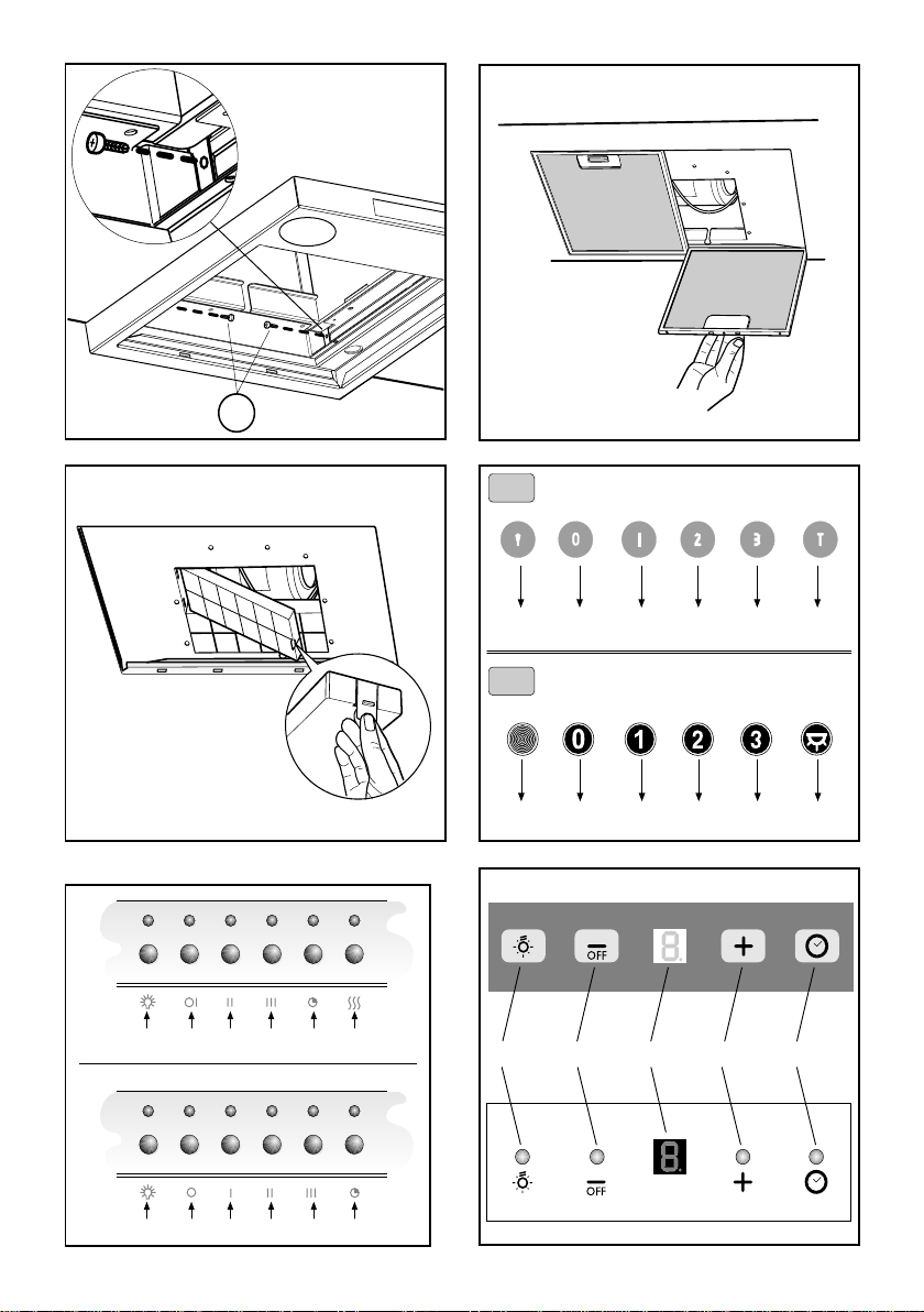
the anti-grease filter(s) (Fig.7) so that the unit is easier
to handle.
- In the case of assembly of the appliance in the suction
version prepare the hole for evacuation of the air.
• FIXING TO THE WALL
Drill the holes A respecting the distances indicated (Fig.2).
Fix the appliance to the wall and align it in horizontal
position to the wall units. When the appliance has been
adjusted, definitely fix the hood using the screws A (Fig.5).
For the various installations use screws and screw anchors suited to the type of wall (e.g. reinforced concrete,
plasterboard, etc.). If the screws and screw anchors are
provided with the product, check that they are suitable
for the type of wall on which the hood is to be fixed.
• FIXING THE DECORATIVE TELESCOPIC FLUE
Arrange the electrical power supply within the dimensions of the decorative flue. If your appliance is to be
installed in the ducting version or in the version with
external motor, prepare the air exhaust opening. Adjust
the width of the support bracket of the upper flue (Fig.3).
Then fix it to the ceiling using the screws A (Fig.3) in
such a way that it is in line with your hood and respecting
the distance from the ceiling indicated in Fig.2. Connect
the flange C to the air exhaust hole using a connection
pipe (Fig.5).
Insert the upper flue into the lower flue. Fix the lower flue
to the hood using the screws B provided (Fig.5), extract
the upper flue up to the bracket and fix it with the screws
B (Fig.3). If your appliance has the lower connections
indicated as in Fig. 4 A, the fixing to be carried out is that
shown in Fig. 6 A
To transform the hood from a ducting version into a
filtering version, ask your dealer for the charcoal filters
and follow the installation instructions.
• FILTERING VERSION
Install the hood and the two flues as described in the
paragraph for installation of the hood in ducting version.
To assemble the filtering flue refer to the instructions
contained in the kit. If the kit is not provided, order it
from your dealer as accessory. The charcoal filters must
be fitted in the ducting unit located inside the hood
(Fig.8).
USE AND MAINTENANCE
• It is recommended to operate the appliance prior to
cooking.
It is recommended to leave the appliance in operation for
15 minutes after cooking is terminated in order to
completely eliminate cooking vapours and odours.
- 5 -

The proper function of the cooker hood is conditioned by
the regularity of the maintenance operations, in particular,
the active carbon filter.
• The anti-grease filters capture the grease particles
suspended in the air, and are therefore subject to clogging
according to the frequency of the use of the appliance.
In order to prevent fire hazard, it is recommendable to
clean the filter at a maximum of 2 months by carrying out
the following instructions:
- Remove the filters from the cooker hood and wash them
in a solution of water and neutral liquid detergent, leaving
to soak.
- Rinse thoroughly with warm water and leave to dry.
- The filters may also be washed in the dishwasher.
The aluminium panels may alter in colour after several
washes. This is not cause for customer complaint nor
replacement of panels.
• The active carbon filters purify the air that is replaced
in the environment. The filters are not washable nor reuseable and must be replaced at maximum every four
months. The saturation of the active carbon filter depends
on the frequency of use of the appliance, by the type of
cooking and the regularity of cleaning the anti-grease
filters.
• Clean the fan and other surfaces of the cooker hood
regularly using a cloth moistened with denatured alcohol
or non abrasive liquid detergent.
• The illumination installation is designed for use during
cooking and not for prolonged general illumination of the
environment. Prolonged use of the illumination installation
notably reduces the duration of the bulb.
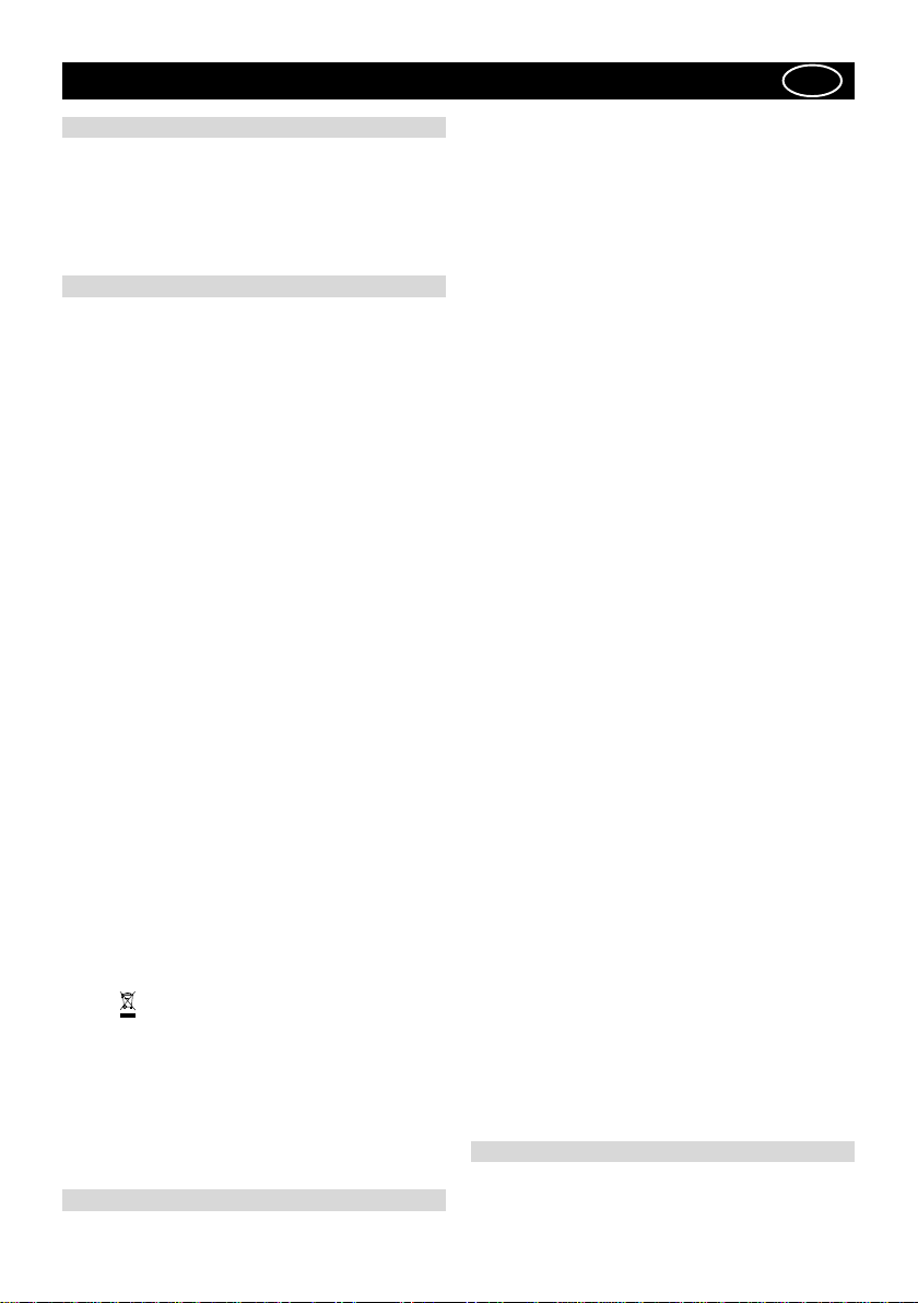
COMANDS: (Fig.11)
Push-button A = on/off lights switch
Push-button B = on/off cooker hood switch. The appli-
ance switches on at speed level 1, If the cooker hood is
on depress the push-button for 2 sec. to switch off the
cooker hood. If the cooker hood is at speed level 1 it will
not be necessary to depress the push-button to switch
the cooker hood off. Decreases the motor speed.
Display C = indicates the motor speed level selected
and activates the timer.
Push-button D = switches on the cooker hood. Increases
the motor speed. Touching the key at 3rd speed, the
intensive function runs for 10', then the appliance go
back to work at the original speed. During this function
the display blinks.
Key E = The Timer times the functions on activation for
15 minutes, after which they are switched off. The Timer
is deactivated by re-pressing Key E. When the Timer is
activated the decimal point must flash on the display.
The Timer cannot be activated if the intensive speed is
functioning.
The “clean air” function is activated by pressing key E
for 2 seconds when the appliance is switched off. This
switches the motor on for 10 minutes every hour at the
first speed. During functioning a rotary movement of the
peripheral segments must be visualised on the display.
When this time has passed the motor switches off and
the fixed letter “C” must be visualised on the display
until the motor re-starts after 50 minutes for another 10
minutes and so on. Press any key apart from the light
keys to return to normal functioning. Press key E to
deactivate the function.
• Active carbon/grease filter saturation: Fig.11
- When display item C flashes, at a speed where it
alternates with the letter F (e.g. 1 and F), the grease
filters must be washed.
- When display item C flashes, at a speed where it
alternates with the letter A (e.g. 1 and A), the carbon
filters must be replaced.
After the clean filter has been positioned correctly, the
electronic memory must be reset by pressing button A
for approximately 5 seconds, until the indication F or A
shown on the display C stops flashing.
• COMAND: ELECTRONIC (Fig.10A):
A = LIGHT
B = OFF/SPEED I
C = SPEED II
D = SPEED III
E = AUTOMATIC STOP TIMER – 15 minutes (*)
F = FILTER SATURATION RESET LIGHT
When the “filter saturation” light flashes, the anti-grease
filters must be washed.
When the light comes on without flashing, the anti-grease
filters must be washed and the carbon filters replaced (in
case of operation whit the recycling version).
When this operation has been completed, press the key
to reset it.
• COMAND: (Fig.9A) LUMINOUS - (Fig.10B) ELECTRONIC
the key symbols are explained below:
A = LIGHT
B = OFF
C = SPEED I
D = SPEED II
E = SPEED III
F = AUTOMATIC STOP TIMER - 15 minutes (*)
• If your appliance does not have the INTENSIVE speed
function, press key E for two seconds and it will be
activated for 10 minutes after which it will return to the
previously set speed.
When the function is active the LED flashes. To interrupt it before the 10 minutes have expired press key E
again.
• By pressing key F for two seconds (with the hood
switched off) the “clean air” function is activated. This
function switches the appliance on for ten minutes every
hour at the first speed. As soon as this function is activated the motor starts up at the first speed for ten
minutes, During this time key F and key C must flash at
the same time.
After ten minutes the motor switches off and the LED of
key F remains switched on with a fixed light until the
motor starts up again at the first speed after fifty minutes and keys F and C start to flash again for ten minutes and so on.
By pressing any key for the exclusion of the hood light
the hood will return immediately to its normal functioning
(e.g. if key D is pressed the “clean air” function is
deactivated and the motor moves to the 2nd speed
straight away. By pressing key B the function is deactivated).
(*) The “automatic stop timer” delays stopping of the
hood, which will continue functioning for 15 minutes at
the operating speed set at the time this function is activated.
• Active carbon/grease filter saturation: Fig.9A / Fig.10B
- When button A flashes at a frequency of 2 seconds,
the grease filters must be cleaned.
- When button A flashes at a frequency of 0.5 seconds,
the carbon filters must be replaced.
After the clean filter has been replaced, the electronic
memory must be reset by pressing button A for
approximately 5 seconds, until the light on the button
stops flashing.
•COMANDS:(Fig.9B) MECHANICAL the key symbols are
explained below:
A = LIGHT
B = OFF
C = SPEED I
D = SPEED II
E = SPEED III
G = MOTOR WORKING indicator
THE MANUFACTURER DECLINES ALL RESPONSIBILITY
FOR EVENTUAL DAMAGES CAUSED BY BREACHING
THE ABOVE WARNINGS.
ČESKY
POLSCPOLSC
ÚVOD’
Přečtěte si pozorně obsah návodu, protože poskytuje
důležité informace týkající se bezpečné instalace,
používání i údržby zařízení. Uchovejte si návod pro
jakoukoliv budoucí potřebu. Přístroj je určen k odsávání
(odvádění vzduchu ven – obr.1B), filtrování (recyklace
vzduchu v místnosti – obr.1A) nebo k použití s externě
umístěným motorem (obr.1C).
BEZPECNOSTNÍ OPATRENÍ
1. Vyžaduje se opatrnost, jestliže jsou současně v
činnosti odsávač par a jiný hořák nebo tepelné zařízení
závisející na vzduchu místnosti a napájené jinou energií
než elektrickou, protože odsávač par spotřebovává
vzduch z okolí, který hořák nebo jiné tepelné zařízení
potřebují ke spalování. Negativní tlak nesmí překročit
4Pa (4x10
odpovídající ventilace místnosti. Při odvádění vzduchu
do vnějšího prostředí je nutné se řídit platnými předpisy
Vaší země.
Před napojením modelu na elektrickou síť:
- Zkontrolujte tabulku s údaji umístěnou uvnitř přístroje a
ověřte si, že napětí a výkon odpovídají místní síti a
rovněž zásuvka je vhodná.
V případě jakékoliv pochyby se poraďte s kvalifikovaným
elektrikářem.
- Je-li napájecí kabel poškozen, musí být nahrazen
speciálním kabelem nebo sadou, které jsou k dispozici u
výrobce nebo v jeho servisním středisku.
2. UPOZORNĚNÍ !
Za určitých okolností mohou být elektrické spotřebiče
nebezpečné.
A) Neprovádějte kontrolu filtrů se zapnutým
B) Nedotýkejte se žárovek a prostoru kolem nich behem
C) Nedotýkejte se žárovek, bylo-li zařízení déle v
D) Je zakázáno upravovat pokrmy manipulí přímého
E) Vyvarujte se volnému plameni, je škodlivý pro filtry
F) Při smažení jídel zajistěte, aby se rozpálený olej
G) Před provedením jakékoliv údržby vypněte přístroj
Toto zařízení je označeno v souladu s Evropskou směrnicí
2002/96/ES, Waste Electrical and Electronic Equipment
(WEEE). Tím, že se uživatel ujistí o správné likvidaci
tohoto výrobku, přispívá k předcházení případným
negativním následkům na životní prostředí a na zdraví.
Symbol
poukazuje na to, že se s tímto výrobkem nesmí zacházet
jako s běžným domovním odpadem, ale musí se odeslat
do vhodné sběrny určené pro recyklaci elektrických a
elektronických zařízení. Zařízení se musíte zbavit
v souladu s místními předpisy pro likvidaci
odpadu.Podrobnější informace o zacházení s tímto
výrobkem, jeho opětovným použitím a recyklací můžete
získat, když se obrátíte na příslušný místní úřad, sběrnou
službu domovního odpadu nebo obchod, ve kterém jste
výrobek zakoupili.
–5
bar). K bezpečnému provozu je tedy nutná
spotřebičem
užití nebo ihned po dlouhodobém užití osvetlovacího
zarízení.
chodu
ohně pod fungujícím odsávačem
a mohl by způsobit požár
nevznítil
z elektrické sítě.
na výrobku nebo na přiložené dokumentaci
NÁVOD K INSTALACI
Operace spojené s montáží a elektrická napojení musí
CZ
být provedeny pouze odborným personálem.
• Elektrické zapojení
Zařízení je vyrobeno v II. třídě, a proto žádný vodič nesmí
být uzemněn.
Napojení k elektrické síti musí být provedeno následovně:
HNĚDÁ = L vodič
MODRÁ = N neutrální vodič
Na přívodní kabel, pokud ji již neobsahuje, namontujte
zástrčku normalizovanou pro příkon uvedený v technických
charakteristikách výrobku.
V případě přímého zapojení na elektrickou síť je nezbytné
přístroj připojit přes vícepólový spínač s minimální vzdáleností
3 mm mezi rozpojenými kontakty, dostatečně dimenzovaný
a odpovídající platným normám.
• Minimální vzdálenost mezi opěrnou plochou varných nádob
na varném zažízení a nejnižším bodem kuchyňského krytu
musí být alespoň 65 cm.
Vývod odsavače nesmí být napojen na vývod, ve kterém
cirkuluje teplý vzduch, nebo který je používán k odvádění
kouře ze zařízení napájených jinou energií než elektrickou.
Před zahájením montáže vyjměte z odsavače tukový filtr
(obr.7). Usnadníte si tak manipulaci s přístrojem.
V případě montáže přístroje ve verzi odsávače je třeba
připravit otvor k evakuaci vzduchu.
• UPEVNĚNÍ KE ZDI
Vyvrtat díry A podle uvedených kót (Obr.2). Odsavač
upevněte ke zdi a vyrovnejte jej do horizontální polohy
pomocí závěsů. Po vyrovnání odsavač definitivně upevněte
prostřednictvím dvou šroubů A (obr.5). Pro různé montážní
podmínky použijte příslušné typy šroubů a hmoždinek, které
budou odpovídat typu zdiva (např. armovaný beton,
sádrokarton atd.). Budou-li šrouby a hmoždinky dodány jako
součást produktu, ujistěte se, zda odpovídají typu zdiva,
na něž má být odsavač namontován.
• MONTÁŽ DEKORATIVNÍCH TELESKOPICKÝCH
SPOJOVACÍCH PRVKŮ
Elektrický přívod protáhněte pod krytem dekoračního spoje.
Má-li být váš přístroj nainstalován ve verzi odsávání nebo
v provedení s externě umístěným motorem, proveďte otvor
pro odtah vzduchu. Nastavte šířku úchytné konzoly horního
spoje (obr .3). Následně ji upevněte ke stropu prostřednictvím
šroubů A (obr.3) takovým způsobem, aby byla v ose s vaším
odsavačem a dodržujte přitom vzdálenost od stropu,
vyznačenou obr.2. Propojit prostřednictvím spojovací roury
přírubu C s otvorem odtahu vzduchu (obr.5).
Vsadit horní spojovací prvek do spodního spojovacího prvku.
Spodní spojovací prvek ke krytu, používajíce šrouby B ve
výbavě (obr. 5), vysunout horní díl až ke třmenu a upevněte
jej pomocí šroubů B (obr. 3).
V případě, že má váš přístroj spoje nižší, jako na obr. 4 A,
připevnění je shodné s obr. 6.A.
Budete-li chtít změnit funkci zařízení z odsavače na filtrační
verzi, vyžádejte si u vašeho prodejce filtry s aktivním uhlíkem
a sledujte montážní pokyny.
• FILTR AČNÍ VERZE
Odsavač a spojovací prvky instalovat tak, jak je uvedeno
v bodu, který se týká montáže krytu ve verzi odsavače. Při
montáži filtrační vložky se řiďte pokyny obsaženými v balení.
Není-li souprava ve výbavě, objednejte ji u svého dodavatele
jako příslušenství. Filtry s aktivním uhlíkem musí být vloženy
do odsávací jednotky odsavače (obr.8).
POUŽITÍ A ÚDRŽBA
• Doporučujeme zapojení přístroje před přípravou
jakéhokoliv vařeného pokrmu.
Doporučujeme nechat odsávač zapnutý po 15 minut po
dovaření jídel, k úplnému odsátí spotřebovaného vzduchu.
- 7 -

Správné fungování odsávače závisí na pravidelném
provádění údržby, zvláště operací k čištění filtru proti
mastnotám a filtru s aktivním uhlíkem.
• Úkolem filtru proti mastnotám je zadržovat částice tuků
rozptýlené ve vzduchu a proto se mohou ucpávat po
různě dlouhé době v závislosti na tom, jak často a jakým
způsobem je odsávač používán.
V každém případě je zapotřebí filtry očistit alespoň jednou
za 2 měsíce a postupovat při tom následovně:
- Odstranit filtry z odsávace a umýt je v roztoku vody a
neutrálního tekutého cistícího prostredku a nechat
rozpustit špínu.
- Opláchnout rádne pod vlažnou vodou a nechat uschnout.
- Filtry lze rovněž umývat v myčce nádobí.
Po několikerém umytí hliníkových panelů může dojít ke
změně jejich barvy. Tato skutečnost neopravňuje k
reklamaci a žádosti o jejich eventuální výměnu.
• Filtry s aktivním uhlíkem slouží k vyčištění vzduchu,
který bude opět uveden do prostředí. Filtry není možné
mýt či obnovovat a musejí být vyměňovány minimálně
každé čtyři měsíce. Saturace aktivního uhlíku závisí na
délce použití odsávače, typu kuchyně a pravidelnosti
čištění filtru proti mastnotám.
• Očistit pravidelně všechny usazeniny na ventilátoru a
ostatním povrchu a použít k tomu hadr navlhčený v
denaturovaném lihu nebo v neutrálních, nebrusných
tekutých čistících prostředcích.
• Osvetlovací zarízení je projektováno pro užití behem
varení a nikoliv pro prodloužené použití za úcelem
celkového osvetlení prostredí. Nadmerné použití
osvetlovacého zarízení podstatne sníží prumerné trvání
žárovek.
OVLÁDÁNÍ (Obr. 11):
Tlačítko A – rozsvítí/zhasne světla
Tlačítko B – zapne/vypne odsávač. Přístroj je uveden do
chodu při první rychlosti. Je-li odsavač zapnutý, vypněte
jej stisknutím tlačítka na 2 sek. Pokud se odsávač nachází
ve fázi první rychlosti, není nezbytné dlouze stisknout
tlačítko za účelem vypnutí. Snižuje se rychlost motoru.
Displej C – ukazuje zvolenou rychlost motoru a uvedení
do chodu časového spínače
Tlačítko D – zapne odsávač. Zvyšuje rychlost motoru.
Stiskne-li se tlačítko od třetí rychlosti, je nastavena
intenzívní funkce na 10 vteřin, pak se přístroj vrátí do
fáze pracovní rychlosti v okamžiku uvedení do chodu.
Během této funkce displej bliká.
Tlačítko E = Časovač slouží k časovému ovládání funkcí
v průběhu 15 minut po jeho aktivaci; po uplynutí uvedené
doby se tyto funkce vypnou. Vypnutí časovače se provádí
stisknutím tlačítka E. Aktivace funkce časovače musí
být signalizována blikáním desetinné tečky na displeji.
Je-li aktivována intenzivní rychlost, aktivace časovače
není možná.
Stisknutím tlačítka E na 2 sekundy při vypnutém zařízení
se aktivuje funkce „clean air“. V rámci této funkce se
motor zapne každou hodinu na 10 minut a během této
doby se bude otáčet první rychlostí. Během jeho činnosti
bude na displeji zobrazen rotační pohyb obvodových
segmentů. Po uplynutí uvedené doby dojde k vypnutí
motoru a na displeji musí být zobrazeno písmeno „C“,
aniž by blikalo, dokud nebude po uplynutí dalších 50
minut motor znovu spuštěn na 10 minut, a tak dále.
• Nasycení protitukových filtrů/filtrů s aktivním uhlím:
Fig.11
- Když displej C bliká a střídavě zobrazuje provozní
rychlost a písmeno F (např.1 a F), je třeba vyčistit
protitukové filtry.
- Když displej C bliká a střídavě zobrazuje provozní
rychlost a písmeno A (např.1 a A), je třeba vyměnit
uhlíkové filtry.
Po vložení čistého filtru je třeba vynulovat elektronickou
paměť stisknutím tlačítka A na dobu přibližně 5 sek.,
dokud signalizace F nebo A na displeji C nepřestane
blikat.
OVLÁDÁNÍ: ELEKTRONIKA (Obr.10A)
Tlačítko A – OSVĚTLENÍ
Tlačítko B – VYPNUTÍ/PRVNÍ RYCHLOST
Tlačítko C – DRUHÁ RYCHLOST
Tlačítko D – TŘETÍ RYCHLOST
Tlačítko E – ČASOVÝ SPÍNAČ AUTOMATICKÉ VYPNUTÍ
15 minut (*)
Tlačítko F – RESET KONTROLKA SATURACE FILTRŮ
Pokud bliká kontrolka „SATURACE FILTRŮ“, je třeba
vyčistit protiolejové filtry.
Pokud se kontrolka rozsvítí a nebliká, je třeba vyčistit
protiolejové filtry a vyměnit uhlíkové filtry (v případě
funkce ve verzi recirkulace). Po dokončení této operace
je třeba stisknout tlačítko za účelem resetování.
OVLÁDÁNÍ:
(Obr.9A) SVĚTELNÉ - (Obr.10B) ELEKTRONIKA následuje
přehled symbolů:
Tlačítko A – OSVĚTLENÍ
Tlačítko B – VYPNUTÍ
Tlačítko C – PRVNÍ RYCHLOST
Tlačítko D – DRUHÁ RYCHLOST
Tlačítko E – TŘETÍ RYCHLOST
Tlačítko F – ČASOVÝ SPÍNAČ AUTOMATICKÉ VYPNUTÍ
15 minut (*)
Pokud je váš prístroj vybven funkcí INTENZÍVNÍ rychlost,
je treba stisknout po dobu aespon 2 s tlacítko E a rychlost
bude aktivována po deset minut a poté se vrátí do
rychlosti, jež byla předem nastavena.
Pokud je funkce aktivní, led bliká. Chcete –li ji přerušit
před vypršením 10 minut, stiskněte znovu klávesu E.
Po stisknutí tlacítka F po dobu 2 s (kryt je vypnut) bude
aktivována funkce „clean air“. Tato funkce zapne motor
na deset minut každou hodinuna první rychlost. Jakmile
bude tato funkce aktivována, motor bude uveden do
chodu na první rychlost po dobu 10 s, behem které
budou blikat soucasne tlacítka F a C. Po uplynutí této
doby se motor vypne a led tlacítka F zustane osvetlen
až do doby, kdy po 50 minutách bude znovu motor uveden
do chodu na první rychlost a led F a C znovu zacnou
blikat po 10 minut a tak dále. Po stisknutí jakéhokoliv
tlacítka s výjimkou svetel se kryt okamžite vrátí do svého
normálního fungování. (napr. pokud se stiskne tlacítko D,
deaktivuje se funkce „clean air“ a motor zacne pracovat
na druhou rychlost, stisknutím tlacítka B se tato funkce
deaktivuje.
(*) Funkce „ČASOVÝ SPÍNAČ AUTOMATICKÉ VYPNUTÍ“
opožďuje vypnutí odsávače, který bude pokračovat ve
funkci pracovní rychlostí, která byla nastavena
v okamžiku zapnutí této funkce, 15 minut.
• Nasycení protitukových filtrů/filtrů s aktivním uhlím:
Obr.9A - Obr.10B
- Blikání tlačítka A frekvencí 2 sek. poukazuje na potřebu
umytí protitukových filtrů.
- Blikání tlačítka A frekvencí 0,5 sek. poukazuje na potřebu
výměny uhlíkových filtrů.
Po vložení čistého filtru je třeba vynulovat elektronickou
paměť stisknutím tlačítka A na dobu přibližně 5 sek.,
dokud tlačítko nepřestane blikat.
OVLÁDÁNÍ: Mechanické (Obr.9B)
Tlačítko A – OSVĚTLENÍ
Tlačítko B – VYPNUTÍ
Tlačítko C – PRVNÍ RYCHLOST
Tlačítko D – DRUHÁ RYCHLOST
Tlačítko E – TŘETÍ RYCHLOST
Tlačítko G - Wskaźnik
VÝROBCE ODMÍTÁ JAKOUKOLIV ZODPOVĚDNOST ZA
ŠKODY ZPŮSOBENÉ NEDODRŽENÍM UVEDENÝCH
UPOZORNĚNÍ.
DANSK
GENERELLE OPLYSNINGER
Læs omhyggeligt indholdet af denne brugsanvisning, da
den giver vigtige oplysninger vedrørende sikkerheden
ved installering, brug og vedligeholdelse. Opbevar brugsanvisningen til senere brug. Apparatet er udarbejdet til at
kunne fungere; udsugende (udledning af luft til eksterne
omgivelser Fig.1B) filtrerende (intern cirkulation af luft
Fig.1A) og med udvendig motor. (Fig.1C).
OPLYSNINGER VEDRØRENDE SIKKERHED
1. Udvis forsigtighed hvis der samtidigt med emhætten er
en varmekilde eller flamme i funktion, som er afhængig af
luften i omgivelserne og forsynet med energi, der ikke er
elektrisk, eftersom emhætten fjerner den luft fra omgivelserne, som flammen eller varmekilden har brug for til
forbrænding. Det negative tryk i lokalet må ikke overstige 4 Pa (4x10⁻⁵ bar). For størst mulig sikkerhed, sørg
for en passende ventilation af rummet. Hvad angår udsugningen til eksterne omgivelser følg de gældende normer.
Før modellen tilsluttes el-nettet:
- Kontrollèr informationsetiketten (placeret indeni apparatet), for at sikre, at spændingen og styrken er i overensstemmelse med el-nettet og at stikkontakterne er
egnede. Hvis De er i tvivl, konsultèr en kvalificeret elektriker.
- Hvis forsyningsledningen er beskadiget, skal den
udskiftes med en ledning eller en særlig samling fra
fabrikanten eller et autoriseret servicecenter.
2. ADVARSEL!
I bestemte situationer kan elektriske hvidevarer være
farlige.
A) Forsøg ikke at kontrollere filtrene mens emhætten
er tændt.
B) Rør ikke ved pærer eller områderne omkring dem
i forbindelse med længere brug af belysningsanlægget
eller straks herefter.
C) Rør ikke ved lamperne efter længerevarende brug
af apparatet.
D) Det er forbudt at flambere under emhætten.
E) Undgå åben flamme da det er skadelig for filtrene
og kan forårsage brand.
F) Hold friturestegning under konstant overvågning for
at undgå, at olien overophedes og bryder i brand.
G) Før man udføre enhver form for vedligeholdelse
skal emhætten være afbrudt fra el-nettet.
Dette apparat er udviklet i overensstemmelse med det
europæiske direktiv 2002/96/EF om affald
af elektrisk og elektronisk udstyr (WEEE). Ved at sikre
sig, at dette produkt bortskaffes på korrekt vis, bidrager
brugeren til at forhindre eventuelle negative miljømæssige
og sundhedsmæssige påvirkninger.
Symbolet
følger med produktet, angiver, at produktet ikke skal
behandles som husholdningsaffald, men at det skal
bortskaffes på passende vis på genbrugsstationer til
elektriske og elektroniske apparater. Apparatet skal
bortskaffes i overensstemmelse med de gældende regler
for bortskaffelse af affald. For yderligere oplysninger om
håndtering, genvinding og genbrug af dette produkt, bedes
man kontakte de lokale myndigheder, teknisk forvaltning
eller forretningen, hvor produktet er købt.
INSTRUKTION VED INSTALLERING
Monteringen og udførelsen af de elektriske forbindelser, skal udføres af specialiseret personale.
Den elektriske forbindelse.
Apparatet er udarbejdet i klasse II, derfor skal der ikke
på produktet eller på dokumentationen, der
DK
tilsluttes et kabel til jordforbindelsen.
Tilslutning til el-nettet skal udføres som følgende:
BRUN = L Linje
BLÅ = N Neutal
Hvis det ikke allerede findes, montèr da et standardstik
beregnet til den forsyning, som er angivet på
etiketten.Hvis der allerede er et stik, sørg da for at det er
let tilgængelig efter installation af apparatet.
I tilfælde af en direkte tilslutning til el-nettet er det nødvendigt at anbringe en flerpolet afbryder med en afstand
mellem kontakterne på minimum 3 mm, mellem apparatet
og nettet. Afbryderen skal passe til el- forsyningen og
være i overenstemmelse med de gældende normer.
• Minimums distancen mellem kogeoverfladen, målt fra
selve kogepladerne, og den nederste del af emhhætten,
skal være mindst 65 cm.Hvis der anvendes et
forbindelsesrør bestående af to eller flere dele, skal den
øverste del placeres udenpå den nederste. Tilslut ikke
udledningen fra emhætten med et rør, hvori der cirkulere
varm luft eller som anvendes til at udlede røg fra apparater,
der ikke bruger elektrisk energi. Inden man begynder
monteringen fjernes filtret (Fig.7) for at gøre håndteringen
af apparatet lettere.
- I de tilfælde, hvor apparatet skal installeres i en
udsugende version, forberedes åbningen til udledning af
luft.
• FASTSPÆNDING TIL VÆG
Lav hullerne A , idet de anviste mål overholdes (Fig.2).
Fastspænd apparatet til væggen og ret ind, til det flugter
med ophænget. Når apparatet er i vater, spændes
emhætten fast ved hjælp af de 2 skruer A (Fig.5).Til
forskellige typer montering anvendes skruer og rawlplugs, der passer til den bestemte type mur (f.eks.
jernbeton, gips osv. ). Hvis skruer og rawlplugs følger
med apparatet, bør man sikre sig, at de egner sig til
væggen, hvor emhætten skal spændes fast.
• FASTSPÆNDING AF DE SAMMENSKYDELIGE
PYNTEPANELER
Indsæt El-tilslutningen i rillen på panelet. Hvis apparatet
skal installeres som aftræksemhætte eller med udvendig
motor, laves først hul til udsugning af luften. Regulér
bredden på det øverste panels ophæng (Fig.3). Spænd
herefter ophænget fast til loftet med skruerne A (Fig.3),
så det er i vinkel med emhætten, idet den anviste afstand til loftet i Fig.2 overholdes. Forbind flangen C til
udsugningshullet ved hjælp af et tilslutningsrør (Fig.5).
Indsæt det øverste panel i det nederste. Fastspænd det
nederste panel til emhætten med de medfølgende skruer
B (Fig.5), træk det øverste panel ud til ophænget og
spænd det fast med skruerne B (Fig.3).
“Hvis Deres apparats nederste skinner sidder som vist i
Fig. 4A, skal de fastgøres som angivet i Fig. 6A.”
Skal emhætten laves om fra aftræk til filtrering, anskaffes kulfiltre hos forhandleren, hvorefter monteringsvejledningen følges.
• FILTRERING
Installér emhætten og de to paneler som vist i kapitlet
om montering af aftræksemhætte. Ved montering af filtret
følges de instruktioner, som følger med sættet. Hvis sættet
ikke følger med apparatet, kan det bestilles som tilbehør
hos forhandleren. Kulfiltre skal anvendes på
udsugningsagregatet inde i emhætten (Fig.8).
BRUG OG VEDLIGEHOLDELSE
• Det anbefales at man sætter apparatet i funktion inden
man begynder tilberedning af madvarer.
Det anbefales at man laser apparatet fungere i 15 minutter
efter at maden er blevet tilberedt, for at den mættede luft
kan blive fjernet helt.
Korrekt funktion af emhætten afhænger af hvor ofte der
udføres vedligeholdelse; dette gælder specielt for filtret
til modvirkning af fedtafsættelse og det aktive kulfilter.
- 9 -
 Loading...