


DDX-3216
OPERATING MANUAL
Version 1.1 November 2001
ENGLISH
www.behringer.com
SAFETY INSTRUCTIONS
CAUTION: To reduce the risk of electric shock, do not remove
the cover (or rear). No user serviceable parts
inside; refer servicing to qualified personnel.
WARNING: To reduce the risk of fire or electric shock, do not
expose this appliance to rain and moisture.
This symbol, wherever it appears, alerts you to the
presence of uninsulated dangerous voltage inside
the enclosure—voltage that may be sufficient to
constitute a risk of shock.
This symbol, wherever it appears, alerts you to
important operating and maintenance instructions
in the accompanying literature. Please, read the
manual.
DETAILED SAFETY INSTRUCTIONS:
All the safety and operation instructions should be read before
the appliance is operated.
Retain instructions:
The safety and operating instructions should be retained for
future reference.
Heed warnings:
All warnings on the appliance and in the operating instructions
should be adhered to.
Follow instructions:
All operation and user instructions should be followed.
Water and moisture:
The appliance should not be used near water (e. g. near a
bathtub, washbowl, kitchen sink, laundry tub, in a wet basement,
or near a swimming pool, etc.).
Ventilation:
The appliance should be situated so that its location or position
does not interfere with its proper ventilaton. For example, the
appliance should not be situated on a bed, sofa rug, or similar
surface that may block the ventilation openings: or placed in a
built-in installation, such as a bookcase or cabinet that may impede
the flow of air through the ventilation openings.
Heat:
The appliance should be situated away from heat sources
such as radiators, heat registers, stoves, or other appliances
(including amplifiers) that produce heat.
Power source:
The appliance should be connected to a power supply only of
the type described in the operating instructions or as marked on
the appliance.
Grounding or polarization:
Precautions should be taken so that the grounding or
polarization means of an appliance is not defeated.
Power-cord protection:
Power supply cords should be routed so that they are not
likely to be walked on or pinched by items placed upon or against
them, paying particular attention to cords and plugs, convenience
receptacles and the point where they exit from the appliance.
Cleaning:
The appliance should be cleaned only as recommended by the
manufacturer.
Non-use periods:
The power cord of the appliance should be unplugged from
the outlet when left unused for a long period of time.
Object and liquid entry:
Care should be taken so that objects do not fall and liquids are
not spilled into the enclosure through openings.
Damage requiring service:
The appliance should be serviced by qualified service
personnel when:
s the power supply cord or the plug has been damaged; or
s objects have fallen, or liquid has been spilled into the
appliance; or
s the appliance has been exposed to rain; or
s the appliance does not appear to operate normally or ex-
hibits a marked change in performance; or
s the appliance has been dropped, or the enclosure damaged.
Servicing:
The user should not attempt to service the appliance beyond
that which is described in the operating instructions. All other
servicing should be referred to qualified service personnel.
2
FOREWORD
Dear Customer,
Welcome to the team of DDX3216 users, and thank you very
much for expressing your confidence in BEHRINGER products
by purchasing the DDX3216.
It is one of my most pleasant tasks to write this letter to you,
because it is the culmination of many months of hard work
delivered by our engineering team to reach a very ambitious
goal: To produce a digital mixer, which fully satisfies your and
our expectations and delivers a superior sound quality, easy
operation and technical specifications. The task to design the
DDX3216 certainly meant a great deal of responsibility, which
we assumed by focusing on you, the discerning user and
musician. It also meant a lot of work and night shifts to accomplish
this goal. But it was fun, too. Developing a product usually brings
a lot of people together, and what a great feeling it is when
everybody who participated in such a project can be proud of
what we’ve achieved.
It is our philosophy to share our joy with you, because you are
the most important member of the BEHRINGER family. With your
highly competent suggestions for new products you’ve greatly
contributed to shaping our company and making it successful. In
return, we guarantee you uncompromising quality (manufactured
under ISO9000 certified management system) as well as excellent
technical and audio properties at an extremely favorable price.
All of this will enable you to fully unfold your creativity without
being hampered by budget constraints.
We are often asked how we manage to produce such highgrade devices at such unbelievably low prices. The answer is
quite simple: it’s you, our customers! Many satisfied customers
means large sales volumes enabling us to get better conditions
of purchase for components, etc. Isn’t it only fair to pass this
benefit back to you? Because we know that your success is
our success, too!
I would like to thank the following people, whose help on “Project
DDX3216” has made it all possible:
s all BEHRINGER users who made valuable contributions with
their suggestions and ideas;
s Joost, Jean, Jos, Jörg, Thomas and Christian whose
passionate work made the DDX3216 a really out-of-theordinary digital mixing console;
s Thorsten and Markus who designed this excellent manual;
s Ina and Volker for the sophisticated mechanics;
s everybody who contributed with great enthusiasm to this
project.
My friends, it’s been worth the trouble.
Thank you very much,
Uli Behringer
CAUTION!
+
Please note that extreme volume levels can damage your hearing and/or headphones. Be sure to use appropriate
volumes levels.
3

Ultra-flexible, automated 32-channel 16-bus digital mixing console
s State-of-the-art 32-channel digital mixing console with 16 internal busses and 8 aux sends for extreme routing flexibility
s High-power floating point DSP technology ensures virtually unlimited internal dynamic range
s Ultra high-resolution 24-bit AKM® A/D and CRYSTAL® D/A converters
s 12 ULN (Ultra Low-Noise) microphone inputs with analog inserts and switchable phantom power
s 4-band fully parametric equalizer, low-cut filter, gate, compressor and phase inverter on all 32 channels with additional delay
function on the first 16 channels
s Four built-in effects processors with first-class algorithms, such as reverb, chorus, flanger, phaser, delay, pitch shifter,
tremolo, lo-fi, LFO filter, ring modulator and more
s 17 ultra-precise, low-noise 100-mm motorized ALPS® faders
s Freely configurable built-in level meters on all channels and channel controls with LED rings, which control any of nine
selectable parameters per channel
s Fully-featured static and dynamic automation functions
s Four freely assignable analog outputs on balanced 1/4" TRS connectors
s Internal input/output patchbay for easy routing of complex signal configurations
s Six master controllers for comfortable push-and-turn functionality
s Large, easy-to-read LCD display with adjustable contrast
s Synchronization to SMPTE, MTC or internal clock
s Dither, word length and noise shaping adjustable for digital main outputs
s Two slots for installation of optionally available digital interfaces based on AES/EBU (8 I/O), ADAT® (16 I/O) or TDIF formats (16 I/O)
s MIDI and RS232 connectors allow communication with a PC or numerous other devices
s Extensive MIDI implementation (MMC, program changes, control changes, MIDI sysex)
s PC card slot for saving/loading various libraries and other settings
s Free PC software for data transmission and management downloadable at www.ddx3216.com (serial cable included)
s 19" rack-mounting kit included
s Manufactured under ISO9000 certified management system
4
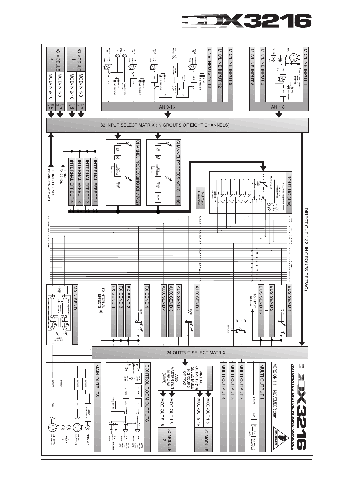
BLOCK DIAGRAM
5

TABLE OF CONTENTS
1. INTRODUCTION.......................................................................................................10
1.1 Digital vs. analog ............................................................................................................................................. 10
1.2 Concept ............................................................................................................................................................ 10
1.2.1 Architecture ........................................................................................................................................ 10
1.2.2 Design concept and componentry .................................................................................................... 11
1.2.3 Open architecture .............................................................................................................................. 11
1.3 Before you begin .............................................................................................................................................. 11
1.3.1 Shipment ........................................................................................................................................... 11
1.3.2 Initial operation .................................................................................................................................. 11
1.3.3 Warranty............................................................................................................................................. 11
2. CONTROL ELEMENTS AND CONNECTORS ........................................................12
2.1 Connection interfaces and control elements on the top side of the DDX3216 .............................................. 1 2
2.1.1 Microphone and line inputs 1-12 ...................................................................................................... 12
2.1.2 Line inputs 13 to 16........................................................................................................................... 12
2.1.3 Phantom power and 2-track inputs/outputs ..................................................................................... 12
2.1.4 Control room and phones sections .................................................................................................. 13
2.2 The rear panel of the DDX3216....................................................................................................................... 13
2.2.1 Control room, multi and main outputs .............................................................................................. 13
2.2.2 Digital S/PDIF and wordclock inputs/outputs ................................................................................... 13
2.2.3 SMPTE and RS232 inputs ................................................................................................................ 13
2.2.4 MIDI connections ............................................................................................................................... 14
2.2.5 Power supply and fuse...................................................................................................................... 14
2.2.6 Option slots 1 and 2 .......................................................................................................................... 14
2.3 PCMCIA card slot ............................................................................................................................................. 14
2.4 Channels and main mix .................................................................................................................................. 14
2.4.1 Channel strips ................................................................................................................................... 14
2.4.2 Main Mix ............................................................................................................................................. 15
2.5 Display ............................................................................................................................................................. 16
2.6 Snapshot automation: switches and displays ................................................................................................ 16
2.7 Left switch block .............................................................................................................................................. 16
2.7.1 Fader bank ........................................................................................................................................ 16
2.7.2 Channel control bank ........................................................................................................................ 17
2.7.3 Proc(ess) bank .................................................................................................................................. 17
2.7.4 General bank ..................................................................................................................................... 17
2.7.5 Auto(mation) bank ............................................................................................................................. 18
3. DIGITAL CHANNEL PROCESSING.........................................................................18
3.1 CHANNEL LIBRARIES..................................................................................................................................... 18
3.2 CHANNEL PROCESSING switches ................................................................................................................19
3.3 A/B function ...................................................................................................................................................... 19
3.4 Equalizer .......................................................................................................................................................... 19
3.4.1 EQ menu page .................................................................................................................................. 19
3.4.2 HIGH PASS menu page .................................................................................................................... 19
3.4.3 EQ LIBRARY menu page .................................................................................................................. 19
3.4.4 EQ parameters .................................................................................................................................. 19
3.5 Dynamics processing ..................................................................................................................................... 20
3.5.1 GATE menu page .............................................................................................................................. 20
3.5.2 COMP(RESSOR) menu page ........................................................................................................... 20
3.5.3 Compressor parameters .................................................................................................................. 20
3.5.4 DYNAMICS LIBRARY menu page ..................................................................................................... 21
3.6 DELAY menu .................................................................................................................................................... 21
4. CHANNEL ROUTING AND BUSSES ......................................................................22
4.1 Channel routing ............................................................................................................................................... 22
4.2 Multi-track bus faders ...................................................................................................................................... 22
4.3 Aux and FX sends ............................................................................................................................................ 22
6

5. EFFECTS PROCESSORS ....................................................................................... 24
5.1 FX menu........................................................................................................................................................... 24
5.1.1 Selecting an effect algorithm............................................................................................................. 24
5.2 Editing effect algorithms .................................................................................................................................. 24
5.2.1 Cathedral ........................................................................................................................................... 24
5.2.2 Plate................................................................................................................................................... 24
5.2.3 Small Hall .......................................................................................................................................... 25
5.2.4 Room ................................................................................................................................................. 25
5.2.5 Concert .............................................................................................................................................. 25
5.2.6 Stage ................................................................................................................................................. 26
5.2.7 Spring Reverb.................................................................................................................................... 26
5.2.8 Gated Reverb..................................................................................................................................... 26
5.2.9 Stereo Delay ...................................................................................................................................... 27
5.2.10 Echo................................................................................................................................................. 27
5.2.11 Stereo Chorus ................................................................................................................................. 27
5.2.12 Stereo Flanger................................................................................................................................. 27
5.2.13 Stereo Phaser ................................................................................................................................. 28
5.2.14 Pitch Shifter ..................................................................................................................................... 28
5.2.15 Delay................................................................................................................................................ 28
5.2.16 Flanger ............................................................................................................................................ 28
5.2.17 Chorus ............................................................................................................................................. 28
5.2.18 Phaser ............................................................................................................................................. 29
5.2.19 Tremolo ........................................................................................................................................... 29
5.2.20 Autopan ........................................................................................................................................... 29
5.2.21 Enhancer ......................................................................................................................................... 29
5.2.22 Graphic Equalizer ............................................................................................................................ 30
5.2.23 LFO Filter ......................................................................................................................................... 30
5.2.24 Auto Filter ......................................................................................................................................... 30
5.2.25 LoFi.................................................................................................................................................. 30
5.2.26 Ring Modulator ................................................................................................................................ 31
6. MONITOR SECTION AND LEVEL METERS ...........................................................31
6.1 MONITOR menu .............................................................................................................................................. 31
6.1.1 Mono/stereo switching ...................................................................................................................... 31
6.1.2 Monitor switching ............................................................................................................................... 32
6.2 Solo function .................................................................................................................................................... 32
6.2.1 Soloing input channels and FX returns ............................................................................................ 32
6.2.2 Soloing aux, FX and master busses................................................................................................. 32
6.3 Level meters .................................................................................................................................................... 32
6.3.1 Channel strip level meters ................................................................................................................ 32
7. GROUPS, PAIRS AND COPY FUNCTIONS ............................................................ 33
7.1 Fader and mute groups ................................................................................................................................... 33
7.1.1 Creating and updating fader and mute groups ................................................................................ 33
7.1.2 Viewing groups .................................................................................................................................. 33
7.1.3 ISOLATE switch ................................................................................................................................. 33
7.2 Pair function ..................................................................................................................................................... 34
7.2.1 Pairing channels ............................................................................................................................... 34
7.2.2 Unpairing channels ........................................................................................................................... 34
7.2.3 Pairing aux sends ............................................................................................................................. 34
7.3 Copying channel settings ................................................................................................................................ 34
8. INPUT/OUTPUT ROUTING ...................................................................................... 3 5
8.1 MULTI outputs .................................................................................................................................................. 35
8.1.1 Assigning signals to the MULTI outputs ........................................................................................... 35
8.2 Input/output routing .......................................................................................................................................... 35
8.2.1 Input routing....................................................................................................................................... 35
8.2.2 Output routing .................................................................................................................................... 35
8.2.3 OUTPUT page in the I/O menu ......................................................................................................... 36
8.2.4 MODULE page in I/O menu............................................................................................................... 36
8.3 Configuring the S/PDIF input and output......................................................................................................... 36
8.3.1 S/PDIF page in the I/O menu............................................................................................................. 36
7

9. FILE MANAGEMENT................................................................................................ 37
9.1 Saving/loading files to/from a computer .......................................................................................................... 37
9.1.1 Communications setup .................................................................................................................... 37
9.1.2 File management .............................................................................................................................. 37
9.2 Using a PC card .............................................................................................................................................. 38
9.2.1 Formatting a PC card ........................................................................................................................ 38
9.2.2 Saving files to a PC card ................................................................................................................... 38
9.2.3 Loading files from a PC card ............................................................................................................ 38
9.2.4 Loading snapshot and library files ................................................................................................... 38
9.2.5 Loading ALL files ............................................................................................................................... 38
9.2.6 Deleting snapshot or library presets ................................................................................................ 38
10. SNAPSHOT AUTOMATION.................................................................................... 38
10.1 Memory contents of a snapshot preset......................................................................................................... 39
10.2 Snapshot automation control elements ....................................................................................................... 39
10.3 Loading snapshots ....................................................................................................................................... 39
10.4 Snapshot Safe function ................................................................................................................................. 39
10.5 Saving snapshots .......................................................................................................................................... 39
1 1. DYNAMIC AUTOMA TION ....................................................................................... 39
11.1 Introduction .................................................................................................................................................... 39
1 1.2 Overview ......................................................................................................................................................... 40
11.2.1 Absolute mode ................................................................................................................................ 40
11.2.2 Relative mode.................................................................................................................................. 40
11.2.3 Various operating modes ................................................................................................................ 40
11.2.4 Snapshots and dynamic automation .............................................................................................. 41
11.2.5 Global automation switches ........................................................................................................... 41
11.2.6 AUTO/REC switches in the channel strips ..................................................................................... 41
1 1.3 DYNAMIC AUTOMA TION menu...................................................................................................................... 41
1 1.3.1 AUTOM. page................................................................................................................................... 41
11.3.2 SETUP page .................................................................................................................................... 42
11.3.3 RECORD page ................................................................................................................................ 42
11.4 Dynamic automation in practice .................................................................................................................... 42
11.4.1 Starting a project.............................................................................................................................. 42
11.4.2 Perfecting a mix ............................................................................................................................... 43
11.4.3 Disabling RECORD—FADEBACK, OFFSET and WR TO END ...................................................... 43
12. SETUP .................................................................................................................... 4 4
12.1 FS CLOCK page ............................................................................................................................................ 44
12.2 Test oscillator ................................................................................................................................................. 44
12.3 PREFS page .................................................................................................................................................. 44
12.3.1 CONFIRMA TION ON OVERWRITE.................................................................................................. 44
12.3.2 CHANNEL MUTE AFTER FADER.................................................................................................... 44
12.3.3 AUTOMA TION AUTO SA VE .............................................................................................................. 45
12.3.4 MAIN CONTROL AS AUX/FX MASTER ............................................................................................ 45
12.3.5 DISPLAY FOLLOWS CHANNEL CONTROL ................................................................................... 45
12.3.6 DISPLAY FOLLOWS AUTOMA TION SWITCHES............................................................................. 45
12.3.7 ONL Y ODD-EVEN P AIRING............................................................................................................. 45
12.3.8 GROUPS FADERPAGE BOUND ..................................................................................................... 45
12.3.9 AUTO CHANNEL SELECT .............................................................................................................. 45
13. MIDI CONTROL ......................................................................................................45
13.1 SETUP page in the MIDI menu...................................................................................................................... 45
13.1.1 Timecode ........................................................................................................................................ 45
13.2 MACHINE CONTROL page in MIDI menu..................................................................................................... 45
13.2.1 MIDI machine control ...................................................................................................................... 45
13.3 RX/TX page in MIDI menu.............................................................................................................................. 46
14. EXPANSIONS .........................................................................................................46
14.1 AES/EBU ........................................................................................................................................................ 47
14.2 ADAT®............................................................................................................................................................. 47
14.3 TDIF-1 ............................................................................................................................................................ 47
8

15. APPLICA TIONS......................................................................................................48
15.1 Studio setups ................................................................................................................................................. 48
15.1.1 DDX3216 in combination with one or several ALESIS® ADAT® or TASCAM® recorders DA-38/DA-78HR . 48
15.2 The DDX3216 in live applications ................................................................................................................. 49
15.2.1 Live recording with the DDX3216.................................................................................................... 49
15.2.2 Sound reinforcement ...................................................................................................................... 49
16. SPECIAL FUNCTIONS........................................................................................... 50
16.1 Updating the DDX3216 operating system .................................................................................................... 50
16.1.1 OS update with PC software ........................................................................................................... 50
16.1.2 OS update with PC card .................................................................................................................. 50
16.2 Recalling the factory presets and automatic fader calibration ..................................................................... 50
17. INST ALLATION....................................................................................................... 51
17.1 Rack mounting .............................................................................................................................................. 51
17.2 Audio connections ......................................................................................................................................... 51
17.2.1 Analog connections ......................................................................................................................... 51
17.2.2 Digital connections (S/PDIF)........................................................................................................... 51
17.3 MIDI ................................................................................................................................................................ 52
18. APPENDIX.............................................................................................................. 53
18.1 MIDI Implementation ..................................................................................................................................... 53
18.2 MIDI Control Changes ................................................................................................................................... 54
19. SPECIFICATIONS .................................................................................................. 55
20. WARRANTY............................................................................................................56
9

1. INTRODUCTION
Thank you very much for expressing your confidence in
BEHRINGER products by purchasing the DDX3216.
The BEHRINGER DDX3216 is an enormously powerful and fullfeatured digital mixing console based on 24-bit technology.
Despite its compact size, the standard version of this console
offers 16 complete inputs, four aux sends, four effect sends, 16
busses, four on-board effects processors and comprehensive
routing options. Optionally available expansion modules
(AES/EBU, ADAT
with 32 digital inputs and 32 digital outputs, so as to connect four
digital 8-track recorders or 24-track hard-disk recording systems.
The twelve ultra low-noise microphone preamplifiers featuring
24-bit CRYSTAL® A/D converters can be enhanced by means of
additional ADAT® or TDIF-compliant 8-channel A/D converters to
make sure that your DDX3216 provides enough connection
options even for major-scale live applications. What is more, the
DDX3216 features static and dynamic automation functions
(“snapshots”) to record parameter changes.
Your DDX3216 is equipped with a large number of ergonomically
placed control elements, which you can use to operate a variety
of functions in a very intuitive way. For example, the console
has 17 faders controlling the levels of 32 input channels, 16
master busses, four aux sends and four internal effect sends
as well as eight effect returns from the on-board effects
processors. The knob, or channel controller on each channel is
even more flexible, as it is always assigned to the same channel
as the fader below it, but it can control any of nine different
parameters on that channel—channel pan or the send level for
one of the four aux or four FX sends. The display with adjustable
contrast gives you a clear picture of various functions, such as
EQ, dynamics, routing, delay, etc. The six master controllers
below the display control the parameters as shown in the display.
To give you maximum flexibility and enable you to work quickly
and intuitively with the DDX3216, we designed the user interface
so that it resembles that of an analog console. The faders made
by ALPS® are motorized, i. e. are automatically set to the correct
position. The channel controllers have LEDs around them
showing their current position. The switches above the faders
are always assigned to the same channel as their faders, and
give you direct access to the solo, mute and select functions. In
addition, there is even a dedicated automation switch per channel.
So, even when the display is used for other control functions,
up to six parameters can be controlled simultaneously using the
rotary controls or master controllers. You will find that the user
interface of your DDX3216 can be operated even more quickly
than that of a huge studio console with hundreds of controls!
®
and TDIF) allow you to upgrade your DDX3216
+ This manual first describes the terminology used,
so that you can fully understand the DDX3216 and
its functions. Please read the manual carefully and
keep it for future reference.
1.1 Digital vs. analog
For quite a long time, the mixing of audio signals has been the
domain of analog mixing consoles. Not only were digital consoles
extremely costly and hence beyond the means of ambitious
amateurs or free-lance owners of project studios, but they were
also looked down upon for lacking the warmth of analog devices.
While digital technologies have found widespread use in effects
processors over the past few years, their prices have gone
down and the concepts of digital mixing consoles have been
reconsidered. Latest research findings in digital signal
processing have made it possible to improve the quality of digital
consoles to such an extent that they are now challenging their
analog competitors. Which benefits do digital mixing consoles
offer?
1. Flexibility in signal processing and routing: since most of
the signal processing is done in the software domain,
designers can let their imagination run free. The functions
implemented in an analog console are determined by the
hardware used, so that later modifications and updates
are usually impossible. The functionalities of digital mixing
consoles, however, can be expanded with the help of
software updates.
2. The mixing results become “predictable”: unlike analog
consoles, which use a sophisticated set of analog components to realize a specific audio result, digital signal
processors always give you predictable results, because
audio signals are processed with the help of so-called
algorithms (calculation rules) based on mathematical formulas and equations. The designers of such algorithms can
use a wealth of sound possibilities greatly exceeding those
of analog circuits and devices.
3. No noise generation during signal processing: since the
entire signal processing takes places in the mathematical
domain, once the signal has been converted from analog
to digital in the A/D converter, no further noise will be
added in the console. The only noise sources in digital
consoles are preamplifiers and A/D converters of poor
quality, and of course noise-affected signals on the input
will be processed with all the noise components they
contain, while “clean” signals will stay clear throughout
the entire console. Analog consoles, however, always
suffer from the basic noise floor produced by their componentry, which inevitably adds noise to the audio signal.
4. Since all parameters and operating steps are realized in
the form of discrete values, they can be easily stored and
automated—in the analog world this feature can be provided by sophisticated and costly consoles only.
A weak point of many digital consoles is their operating concept.
Often, the entire console and all its functions must be operated
from just a few control elements. As you will see in this manual,
it can be done differently. The DDX3216 allows you to operate
each single parameter quickly and intuitively using separate and
dedicated controls. Seeing is believing!
1.2 Concept
1.2.1 Architecture
In its basic version, the DDX3216 is equipped with 16 (+ 2)
analog inputs and ten analog outputs, and can be expanded to
32 inputs and 32 outputs (16 at the same time). Each expansion
card contains 8 or 16 digital inputs/outputs for the integration of
digital multi-track or hard-disk recorders, samplers, MIDI modules,
external digital effects or additional A/D and D/A converters.
Expansion cards are available for the standard digital formats
AES/EBU (8 I/O), ADAT® (16 I/O) and TDIF (16 I/O).
The analog interface section of your DDX3216 comprises 12
mic/line inputs; inputs 13-16 are exclusively designed for linelevel signals. An analog 2-track input allows you to connect a
2-track master recorder and can be assigned to inputs 15 and 16.
The main (XLR, balanced), control room (1/4" TRS, balanced),
phones and four multi outputs (1/4" TRS, balanced) are analog.
The multi outputs are wired to busses aux 1-4, but can be used
individually for any one of the 28 busses available on the DDX3216
(bus 1-16, aux 1-4, FX 1-4, solo L+R and main L+R).
The standard configuration of your DDX3216 also includes a
digital S/PDIF input/output. The digital input is fitted with a sample
rate converter to avoid synchronization problems, and can replace
input channels 13/14. The digital output carries a digital version
of the main output, e. g. to connect a DAT recorder.
When fitted with one of the optional I/O modules, inputs 17-32
become really useful, as they have all of the functionalities of
inputs 1-16, except for the channel delay feature. Also, with an
I/O module fitted, full use can be made of the console’s 16 busses
and comprehensive routing facilities.
10
1. INTRODUCTION

1.2.2 Design concept and componentry
The philosophy behind BEHRINGER products guarantees a
no-compromise circuit design and employs the best choice of
components. The operational amplifiers used in the DDX3216
are exceptional. They boast extreme linearity and very low
distortion characteristics. The 24-bit AKM® A/D and CRYSTAL
D/A converters feature excellent technical specifications and
audio properties, reproducing even the tiniest details of the analog
input signal. All computations are performed by four state-ofthe-art SHARC® DSPs made by ANALOG DEVICES®. The
professional motorized faders made by ALPS® are of excellent
quality and offer you maximum precision as well as smooth and
low-noise operation—even after many years of use—so as to
reproduce level settings with highest accuracy. To complement
this design the choice of components includes low-tolerance
resistors and capacitors and several other stringently selected
elements.
The DDX3216 uses SMD technology (Surface Mounted
Device). These subminiature components adapted from
aerospace technology allow for an extreme packing density to
further improve the console’s overall reliability. Additionally, your
DDX3216 was manufactured in compliance with the ISO9000
certified management system.
1.2.3 Open architecture
As the operating system (firmware) of your DDX3216 is stored
in a flash ROM, you can update the OS at any time from a personal
computer or PC card.
We are committed to improving the DDX3216 operating
software, working on new algorithms and considering your ideas
and suggestions. The resulting software updates will be made
available free of charge on the Internet, so as to ensure that
your DDX3216 will never outdate.
What is more, we will establish a forum on our web site at
www.behringer.com, from where you can download a wealth
of additional information on your DDX3216 (e. g. user manual
updates, presets for various libraries, etc.). Also, you can share
your experience with other users and keep yourself informed
about latest modifications and upgrades for your DDX3216.
+ Please ensure that only qualified personnel install
and operate the DDX3216. During installation and
operation, the user must have sufficient electrical
contact to earth, otherwise electrostatic charges
might affect the operation of the unit.
®
1.3.3 Warranty
Please take the time to fill out and return the warranty card
within 14 days after the date of purchase, so as to be entitled to
benefit from our extended warranty. Or use our online registration
option available on the World Wide Web at www.behringer.com.
1.3 Before you begin
1.3.1 Shipment
Your DDX3216 was carefully packed in the factory and the
packaging is designed to protect the unit from rough handling.
Nevertheless, we recommend that you carefully examine the
packaging and its contents for any signs of physical damage,
which may have occurred during transit.
+ If the unit is damaged, please do not return it to
BEHRINGER, but notify your dealer and the shipping
company immediately, otherwise claims for damage
or replacement may not be granted. Shipping claims
must be made by the consignee.
1.3.2 Initial operation
Be sure that there is enough space around the unit for cooling
and please do not place the DDX3216 on high-temperature
devices such as radiators or power amps etc. to avoid
overheating.
Please use the enclosed power cord to connect the unit to the
mains. The cord complies with all applicable safety standards.
Blown fuses may only be replaced by fuses of the same type
and rating.
+ Please note that all units must be grounded
properly. For your own safety, you should never
remove any ground connectors from electrical
devices or power cords, or render them inoperative.
1. INTRODUCTION
11
2. CONTROL ELEMENTS AND
CONNECTORS
This chapter describes the various control elements of your
DDX3216. Analog controls and connectors will be discussed in
full detail.
2.1 Connection interfaces and control elements
on the top side of the DDX3216
The connectors and controls for the analog inputs are located
in the upper section of the DDX3216. Ex factory, the analog
inputs are assigned to channels 1-16.
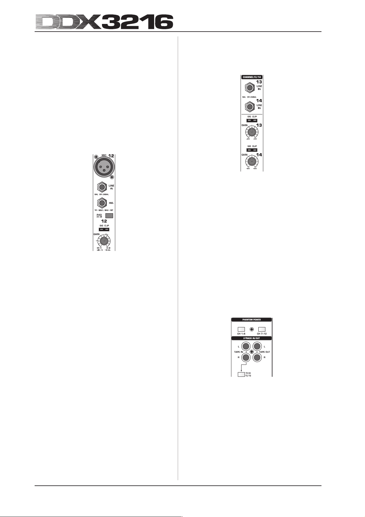
2.1.1 Microphone and line inputs 1-12
The inputs 1-12 are mic/line inputs and have analog insert
points (ISR = Insert Send Return).
Fig. 2.1: Connectors and controls of analog mic/line inputs
MIC
The microphone inputs are on balanced XLR connectors and
feature a switchable phantom power supply for condenser mics
(cf. chapter 2.1.3 “Phantom power and 2-track inputs/outputs”).
LINE IN
The line inputs are on balanced 1/4" TRS connectors and
function in parallel to the microphone inputs.
INSERT
The insert points are on 1/4" TRS connectors (tip = send, i. e.
connection with input of external device; ring = return, i. e.
connection with output of external device; shaft = ground, cf.
chapter 17.2.1 “Analog connections”). In this way, you can insert
analog signal processing devices before the channel’s A/D
converters. Use commercially available insert cables (1/4" TRS
on 2 x 1/4" phone connectors) for this connection. Insert points
are very useful when you need to process channel signals with
dynamic processors or equalizers. The insert points can also be
used as tape sends to a multi-track recorder.
PAD
This attenuation switch (PAD) for line-level signals (or
microphones with very high output levels) reduces the input
gain by 20 dB.
SIG and CLIP LEDs
These LEDs monitor the analog signal level after the insert point.
When gain ist closed, the SIG LED lights at approx. -46 dBu (mic)/
-23 dBu (line) indicating the presence of audio. The CLIP LED
lights at approx. 0 dBu (mic)/+23 dBu (line) and warns you of
signal distortion.
+ Make sure that the CLIP LED does not light up.
GAIN
Use the GAIN control to adjust the mic/line input signal gain.
The setting range is from +10 dB to +60 dB for the XLR input, and
from -10 dB to +40 dB for the 1/4" TRS input.
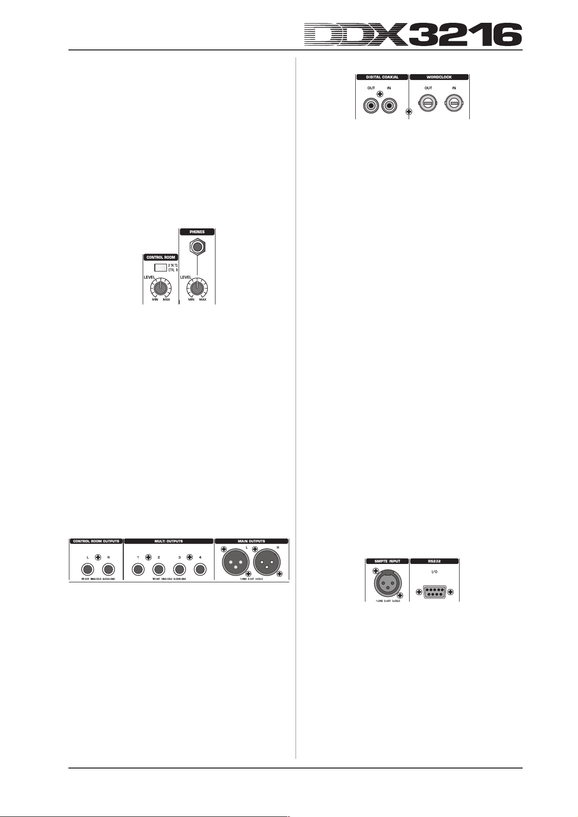
2.1.2 Line inputs 13 to 16
Inputs 13-16 are on balanced 1/4" TRS connectors and can be
used for line-level signals only.
Fig. 2.2: Connectors and controls for inputs 13-16
LINE IN
The line inputs are on balanced 1/4" TRS connectors.
SIG and CLIP LEDs
These LEDs monitor the analog signal level after the insert
point. When gain is in center position, the SIG LED lights at approx.
-36 dBu (unity gain) indicating the presence of audio. The CLIP
LED lights at approx. +10 dBu (unity gain) and warns you of
signal distortion.
GAIN
Use the GAIN control to adjust the line input signal gain. The
setting range is from -20 dB to +20 dB.
+ On the S/PDIF page in the I/O menu, you can assign
the inputs of channels 13/14 to the digital S/PDIF
input. When S/PDIF is selected as the signal source
for channels 13/14, the “normal” channel input
signals are replaced by the signals present at the
digital S/PDIF input.
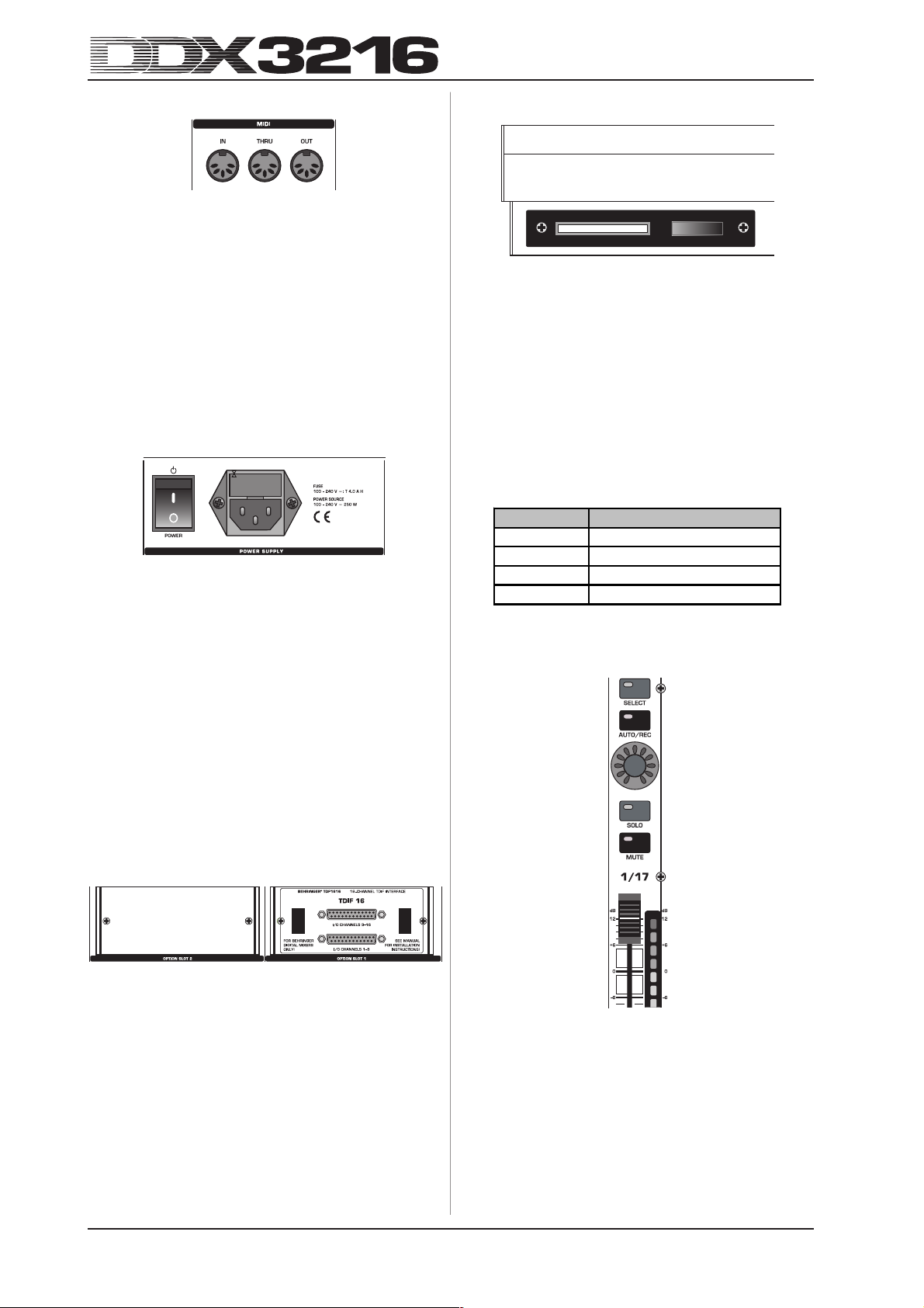
2.1.3 Phantom power and 2-track inputs/outputs
Fig. 2.3: Phantom power and 2-track inputs/outputs
The +48 V phantom power required for condenser mics can
be activated separately for channels 1-6 and 7-12. The
associated switches light up when phantom power is on.
CH. 1-6
This switch activates the phantom power supply for microphone
channels 1-6.
CH. 7-12
This switch activates the phantom power supply for microphone
channels 7-12.
+ Please mute your audio system before you activate
the phantom power supply, so as to prevent switchon thumps from being passed on to your monitor
speakers and/or headphones.
12
2. CONTROL ELEMENTS AND CONNECTORS
TAPE IN
These RCA connectors (nominal level: -10 dBV) are used to
return the signals from a stereo master recorder.
+ Press the 2 TK TO CTRL R switch to monitor the
TAPE INPUTS via the control room and/or phones
outputs.
TAPE OUT
These RCA connectors are wired in parallel to the MAIN OUT
and provide the main mix signal with a nominal level of -10 dBV
(unbalanced).
TO CH 15/16
This switch sends the signal present at the TAPE IN connectors
to channels 15/16, and disables line inputs 15/16.
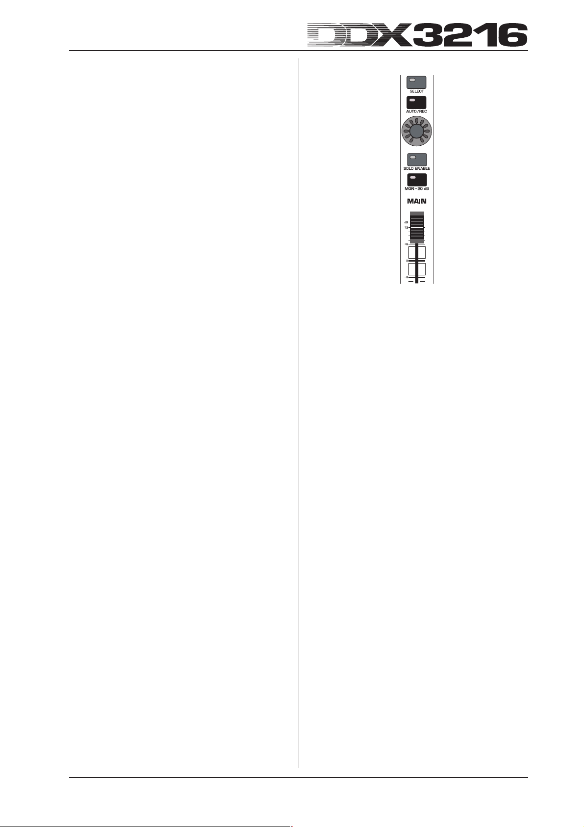
2.1.4 Control room and phones sections
Fig. 2.4: Control room and phones sections
2 TK TO CTRL R
Press this switch to route the signal applied to the TAPE IN to
the control room and phones outputs.
LEVEL (control room)
This LEVEL control adjusts the control room output level.
+ You can also select other signals in the MONITOR
menu (see chapter 6.1 ”MONITOR menu”) and route
them to the control room output.
PHONES connector
Connect your headphones to this 1/4" TRS connector. The
PHONES signal and the CONTROL ROOM signal are identical.
LEVEL (phones)
This LEVEL control determines the headphones volume and
works independently of the control room LEVEL control.
2.2.2 Digital S/PDIF and wordclock inputs/outputs
Fig. 2.6: Digital S/PDIF and wordclock inputs/outputs
DIGITAL COAXIAL OUT
The digital coaxial output (RCA) provides the MAIN MIX signal
in a digital S/PDIF format. The parameters word length and dither
for the digital output can be adjusted on the S/PDIF page in the I/O
menu.
DIGITAL COAXIAL IN
This RCA connector allows you to feed in S/PDIF signals, with
a sampling rate between 32 and 50 kHz. The input is fitted with
a sample rate converter, so as to be able to feed in digital signals
with a sample rate other than that used by the DDX3216.
The S/PDIF input can be routed exclusively to channels 13/14,
replacing the input signal connected to these inputs (see S/PDIF
in I/O menu).
If the DDX3216 is operated via its digital connectors, all digital
devices connected to the console must be synchronized to a
common wordclock rate. With an (optionally available) I/O module
installed and devices such as digital multi-track recorders
connected via digital leads, one of these devices must be defined
as the wordclock master providing the clock rate for all other
units. For this purpose, the DDX3216 generates internal clock
rates of 44.1 or 48 kHz. In slave mode the console can be clocked
via its wordclock input or from an device connected to an I/O
module. The wordclock signal source is adjusted on the
FS CLOCK page in the SETUP menu.
Wordclock signals are usually distributed in a network
configuration, i. e. using 75-Ω coaxial cables, BNC-T adapters
and terminating resistors.
WORDCLOCK OUT
The word clock output is on a BNC connector and provides a
wordclock signal with the sample rate used by the console (TTL
level square wave).
WORDCLOCK IN
The wordclock Input is on a BNC coaxial connector and accepts
wordclock signals between 40 and 50 kHz.
2.2 The rear panel of the DDX3216
2.2.1 Control room, multi and main outputs
Fig. 2.5: Control room, multi and main outputs
CONTROL ROOM OUTPUTS
Normally, the control room output is connected to the monitor
system set up in the control room and provides the stereo main
mix or specific solo signals. The outputs are on balanced 1/4"
TRS connectors with a nominal level of +4 dBu.
MULTI OUTPUTS
The MULTI outputs can carry any of the 28 bus signals in your
DDX3216, i. e. aux outputs, FX sends, stereo main mix, stereo
solo bus or one of the 16 master bus signals. The outputs must
be assigned accordingly on the MULTI page in the I/O menu
(default: aux sends 1-4). The MULTI outputs are on balanced
1/4" TRS connectors with a nominal level of +4 dBu.
MAIN OUTPUTS
The MAIN outputs provide the MAIN MIX signal and are on
balanced XLR connectors with a nominal level of +4 dBu.
2. CONTROL ELEMENTS AND CONNECTORS
+ If you encounter problems with the reception of
word clock signals, you can connect a 75-ohm
resistor to the wordclock input of the DDX3216.
2.2.3 SMPTE and RS232 inputs
Fig. 2.7: SMPTE and RS232 inputs
SMPTE INPUT
The timecode input (XLR-3) accepts SMPTE timecode signals
for the control of the console’s dynamic automation. Usually, such
signals are provided by a computer, video or multi-track recorder.
The frame rate and incoming timecode are displayed on the SETUP
pages in the MIDI and DYNAMIC AUTOMATION menus.
RS232 I/O
The 9-pin RS232 connector enables the DDX3216 to communicate with a computer. For example, you can save and load files,
or update the DDX3216 operating system.
Of course, you will find an appropriate serial cable (1:1) for
the connection to the serial interface of your personal computer
included with your DDX3216.
13
2.2.4 MIDI connections
Fig. 2.8: MIDI connections
The MIDI connectors on the rear of the console are on
internationally standardized 5-pin DIN jacks. Use MIDI cables to
connect your DDX3216 to other MIDI equipment. Such cables are
commercially available, their length should not exceed 50 feet.
The data are transmitted via electrically isolated optocouplers.
MIDI IN: use this input to receive MIDI control data.
MIDI THRU: this connector provides an identical copy of the
MIDI signal received at the MIDI IN jack.
MIDI OUT: use this output to transmit data to a connected
computer or other MIDI equipment.
2.2.5 Power supply and fuse
Fig. 2.9: Power supply and fuse
POWER switch
Use the POWER switch to turn the DDX3216 on and off.
FUSE HOLDER
Use the enclosed IEC power cord to connect the unit to the
mains. It complies with all applicable safety standards. Blown
fuses must always be replaced by fuses of the same type and
rating.
IEC MAINS CONNECTOR
Use this mains connector and the enclosed power cord to
connect the unit to the mains.
SERIAL NUMBER
Please take the time to fill in and return the warranty card
within 14 days after the date of purchase, so as to benefit from
our extended warranty. Or use our online registration option
available on the World Wide Web at www.behringer.com.
2.3 PCMCIA card slot
Fig. 2.11: PCMCIA card slot
The PCMCIA card slot is used to exchange data between the
DDX3216 and a PC card equipped with a flash memory.
+ Only use PC cards of the “5 V ATA Flash Card” type
(any memory capacity permitted).
2.4 Channels and main mix
The DDX3216 features 16 identical channel strips controlling all
of the 32 inputs, 16 master busses, four aux and four FX sends
as well as eight returns from the built-in effects devices. For this
purpose, your DDX3216 has four fader banks with 16 channels
each. The MAIN fader always controls the stereo main mix.
Fader bank Channels
CH 1-16 Channels 1 to 16
CH 17-32 Channels 17 to 32
BUS OUT 1-16 Busses 1 to 16
AUX/FX Aux/FX sends and FX ret urn s
Tab. 2.1: Four fader banks and associated channels
2.4.1 Channel strips
2.2.6 Option slots 1 and 2
Fig. 2.10: Option slots 1 and 2
These two option slots allow you to expand your DDX3216 by
means of two optionally available expansion cards, which are
equipped with various digital connectors (AES/EBU, ADAT® and
TDIF).
Fig. 2.10 shows a TDIF module installed in slot 1. The second
slot is not in use and has a blank panel attached.
+ A detailed installation manual is enclosed with each
optionally available expansion card.
14
2. CONTROL ELEMENTS AND CONNECTORS
Fig. 2.12: Channel strip
Each of the 16 channel strips has the following firmly assigned
control elements:
Channel fader
The channel faders are 100-mm motorized faders made by
ALPS®. Their function depends on what is selected in the fader
banks.
Channel level meter
Each fader has a channel level meter assigned to it. Depending
on the active fader bank, this meter reads the pre-fader or preprocessing levels (inputs), or the post-fader output level (outputs
such as bus, aux and FX). Normally, the channel meter follows
the fader bank settings and reads the level of its associated
fader. However, it can also display the levels of a fader bank
preset in the METERS menu. For example, the meters can read
channels 1-16, while the faders actually control channels 17-32.
Always use the highest levels possible, but make sure that the
red CLIP LED does not light up. Clipping can be the source of
unpleasant digital distortion in the input/output sections of a digital
console, where the signals are converted into analog or fixedpoint digital signals.
CHANNEL CONTROL
The channel controller above the faders is basically assigned
to the same channel as the fader located below it. Depending on
what has been selected in the CHANNEL CONTROL bank, it can
adjust up to nine different parameters of the channel (pan or the
send level for one of the four aux or FX sends). The eleven LEDs
grouped around the controller read its current position.
The channel controller functions are not enabled for all
channels in the various fader banks. For example, the bus output
have no aux, FX send or pan controls. In this case, the channel
controllers are inoperative, their LEDs do not light up.
SELECT switch
Use the SELECT switch to select a channel for on-screen
editing, and for pairing or grouping several channels. Normally,
only one channel can be selected at a time. When you select a
channel that belongs to a channel pair, the SELECT switch of the
other channel starts flashing. Now, all changes made to the
selected channel will affect the other channel as well. When
you select a channel that belongs to a group of channels, only
the fader setting will be transferred to the other group channels.
AUTO/REC switch
The AUTO/REC button controls the dynamic automation (see
chapter 11 “DYNAMIC AUTOMATION”). When automation is off
(AUTOMATION menu via SETUP switch), the AUTO/REC switch
activates the SNAPSHOT SAFE function, which is indicated by a
flashing green LED in the switch. A channel in SNAPSHOT SAFE
mode remains unaffected when you load a stored snapshot
(RECALL).
SOLO switch
The SOLO switch sends the signal of the selected channel to
a solo bus that is routed to the control room and/or phones
outputs. The MAIN MIX signal is unaffected by this switch. Both
PFL (pre-fader listening) and AFL (after-fader listing) modes are
available and displayed in the MONITOR menu. For solo to function,
the SOLO ENABLE switch in the main channel strip must be
pressed and the 2 TK TO CTRL R switch must be off. All channels
(even those muted) can be soloed.
The solo function is available for all input channels, effect
returns, master busses and aux/FX masters. Any number of
input channels and FX returns can be routed simultaneously to
the solo bus, but only two output channels (master bus and aux/
FX master). When you select a third channel, the first channel
soloed will be disabled automatically. More information on the
solo function can be found in chapter 6.2 “Solo function”.
MUTE switch
The MUTE switch mutes the channel. The GROUP function
allows you to create MUTE groups. Muted channels can still be
soloed. The MUTE switch has two operating modes: pre or postfader (PREFS page in SETUP menu). When CHANNEL MUTE
AFTER FADER is on, the MUTE switch is effective only on the
post-fader send signals or the post-fader bus routing. When
CHANNEL MUTE AFTER FADER is off, all sends and the entire
bus routing (both pre and post-fader) are muted.
2.4.2 Main Mix
Fig. 2.13: MAIN fader
MAIN fader
The MAIN fader controls the level of the stereo main mix, which
is also indicated by the MAIN meter in the display.
CHANNEL CONTROL
The channel controller in the MAIN strip works like the channel
controllers in the channel strips. It controls the BALANCE of the
left/right main signals. As long as MAIN CONTROL AS AUX/FX
MASTER is activated on the PREFS page in the SETUP menu, the
channel controller additionally adjusts one of the aux/FX master
send levels. Use one of the CHANNEL CONTROL buttons in the
left switch block in order to select the relevant aux/FX master
send (see chapter 12.3.4 “MAIN CONTROL AS AUX/FX MASTER”).
SELECT switch
The SELECT switch selects the MAIN strip for on-screen editing.
AUTO/REC switch
The AUTO/REC switch controls the dynamic automation. When
automation is off, the AUTO/REC switch activates the SNAPSHOT
SAFE function, which is indicated by a flashing green LED in the
switch. A channel in SNAPSHOT SAFE mode remains unaffected
when you load a stored snapshot (RECALL).
SOLO ENABLE switch
The SOLO ENABLE switch activates the solo function, which
replaces the main mix signal in the control room or phones outputs
by the selected channel signal. When SOLO ENABLE is off, the
solo function is not available, i. e. pressing a SOLO switch in an
input/output channel will have no effect.
When SOLO ENABLE is on, the solo bus is routed to the control
room bus, as soon as you press one of the channel SOLO
switches; the LED of the SOLO ENABLE switch starts flashing.
Pressing SOLO ENABLE again will cancel all solo settings.
+ When the 2 TK TO CTRL R switch is pressed, the
solo signal is not routed to the control room output.
MON -20 dB switch
This switch reduces the level of the signal sent to the control
room output by 20 dB. When the 2 TK TO CTRL R switch is
pressed, this function has no effect on the control room signal.
2. CONTROL ELEMENTS AND CONNECTORS
15
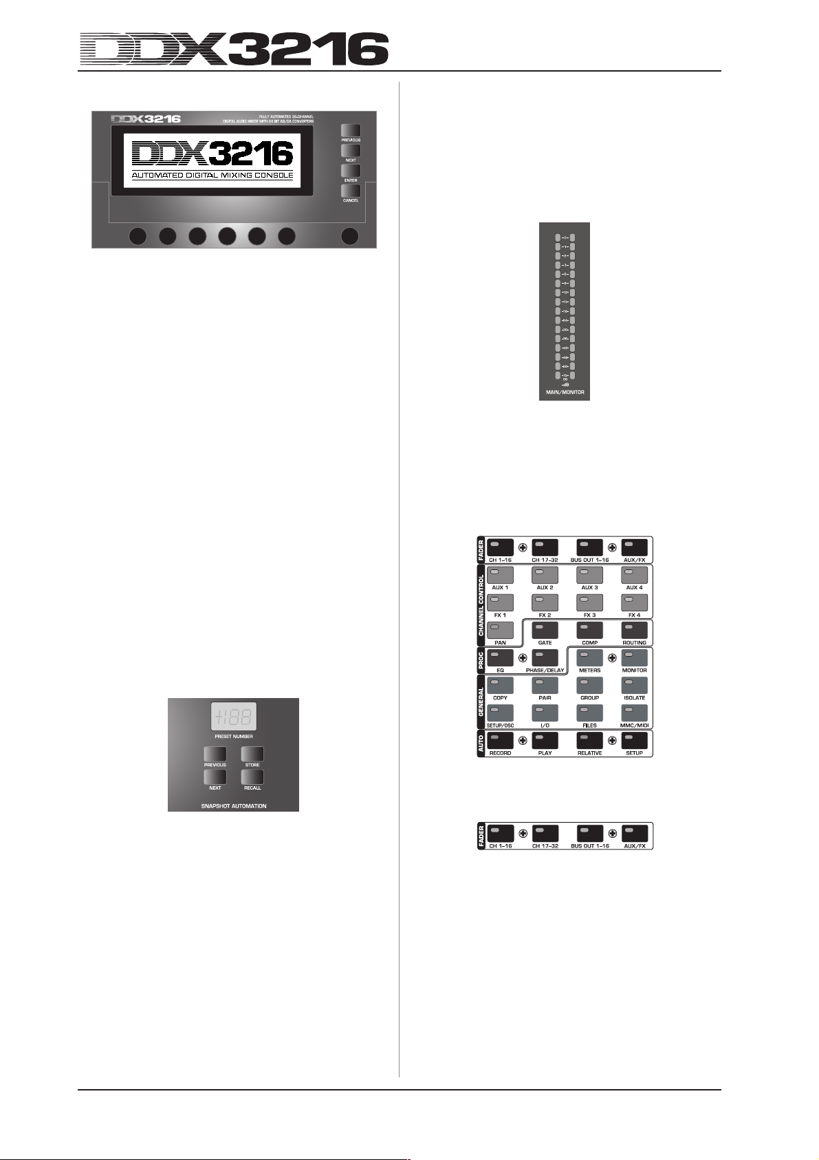
2.5 Display
Fig. 2.14: Display with control elements
Many functions of your mixing console are controlled via the
display, including the general setup, channel processing and the
built-in effects processors. By pressing a switch in the switch
block, you can display whole groups of associated menu pages.
Each group has a menu bar on the upper right side, and each
single menu page has a tab along the top left part of the display.
A thick black line surrounding the tab indicates the active display
page. Press the keys in the switch block to the left of the display
or the PREVIOUS and NEXT switches to scroll through the
available pages.
The contrast knob on the right below the display allows you to
adjust the display brilliance to suit the lighting conditions and
viewing angle.
Master control
The six master controllers just below the display operate the
controls depicted in the display. They function like the channel
controllers, but feature an additional function which is enabled
by pressing the respective controller.
Navigation switches
Use the PREVIOUS and NEXT switches to move from page to
page within one specific menu. Another way to navigate through
the various menu pages is to repeatedly press a switch from the
switch block located to the left of the display. The CANCEL
switch activates the CANCEL button in various menu pages and
dialog boxes, while the ENTER switch performs different
functions in the menu pages and dialog boxes.
RECALL
Recalls the snapshot stored in the selected automation memory.
PRESET NUMBER display
This display reads the number of the current preset or the one
that has been selected for loading. After selection with the
PREVIOUS and NEXT switches, the display shows a decimal
point indicating that the preset has not been recalled yet. Press
the RECALL switch to confirm your selection; the point in the
display disappears.
Fig. 2.16: MAIN/MONITOR level meters
MAIN/MONITOR level meter
Depending on the current configuration, this level meter displays
the MAIN or MONITOR bus levels. When the solo function is
enabled, you can also meter the level of the solo bus.
2.7 Left switch block
2.6 Snapshot automation: switches and displays
Fig. 2.15: Snapshot automation
Almost all settings for the control of audio parameters, except
for the analog level controls, can be stored in any of the 128
snapshot automation memories. The switches and LED display
in the snapshot automation section give you direct access to
these memory locations. Further information on this can be found
in chapter 10 “SNAPSHOT AUTOMATION”.
NEXT
Selects the next highest automation memory, and displays the
SNAPSHOT AUTOMATION menu.
PREVIOUS
Selects the next lowest automation memory, and displays the
SNAPSHOT AUTOMATION menu.
STORE
Displays the STORE SNAPSHOT menu, in which you can name
and store the current settings of the console.
Fig. 2.17: Left switch block
2.7.1 Fader bank
Fig. 2.18: Fader bank
The 16 channel strips are used to control all 32 inputs and 16
master busses, the four aux and four effect masters as well as
the eight returns from the built-in effects units. To this end, your
console has four fader banks with 16 channel strips each. The
master fader always controls the stereo main mix.
The fader bank switches (CH 1-16, CH 17-32, BUS OUT 1-16
and AUX/FX) select the active fader bank. The switches and
controls in the channel strips are always assigned to the same
channel as the faders.
The fader menu reads the levels of all faders in the current
fader bank. If faders or mutes have been organized in groups,
each group has a specific letter assigned to it in the square field
above the faders (mute groups on top of fader groups). All
faders or mutes with the same letter are grouped together.
16
2. CONTROL ELEMENTS AND CONNECTORS
Groups can span more than one fader menu page.
A second press on the fader bank switches CH 1-16 or
CH 17-32 displays the CHANNEL LIB page, where you can save
and recall all channel processing settings for the selected channel.
To navigate between the two menu pages, either press the
corresponding fader bank switch or use the PREVIOUS and
NEXT switches to the right of the display.
2.7.2 Channel control bank
comprise several pages. Use the PREVIOUS and NEXT switches
to the right of the display to scroll through the available menu
pages (or press the CHANNEL PROCESSING switch several
times). The channel processing functions are described in full
detail in chapter 3 “DIGITAL CHANNEL PROCESSING”.
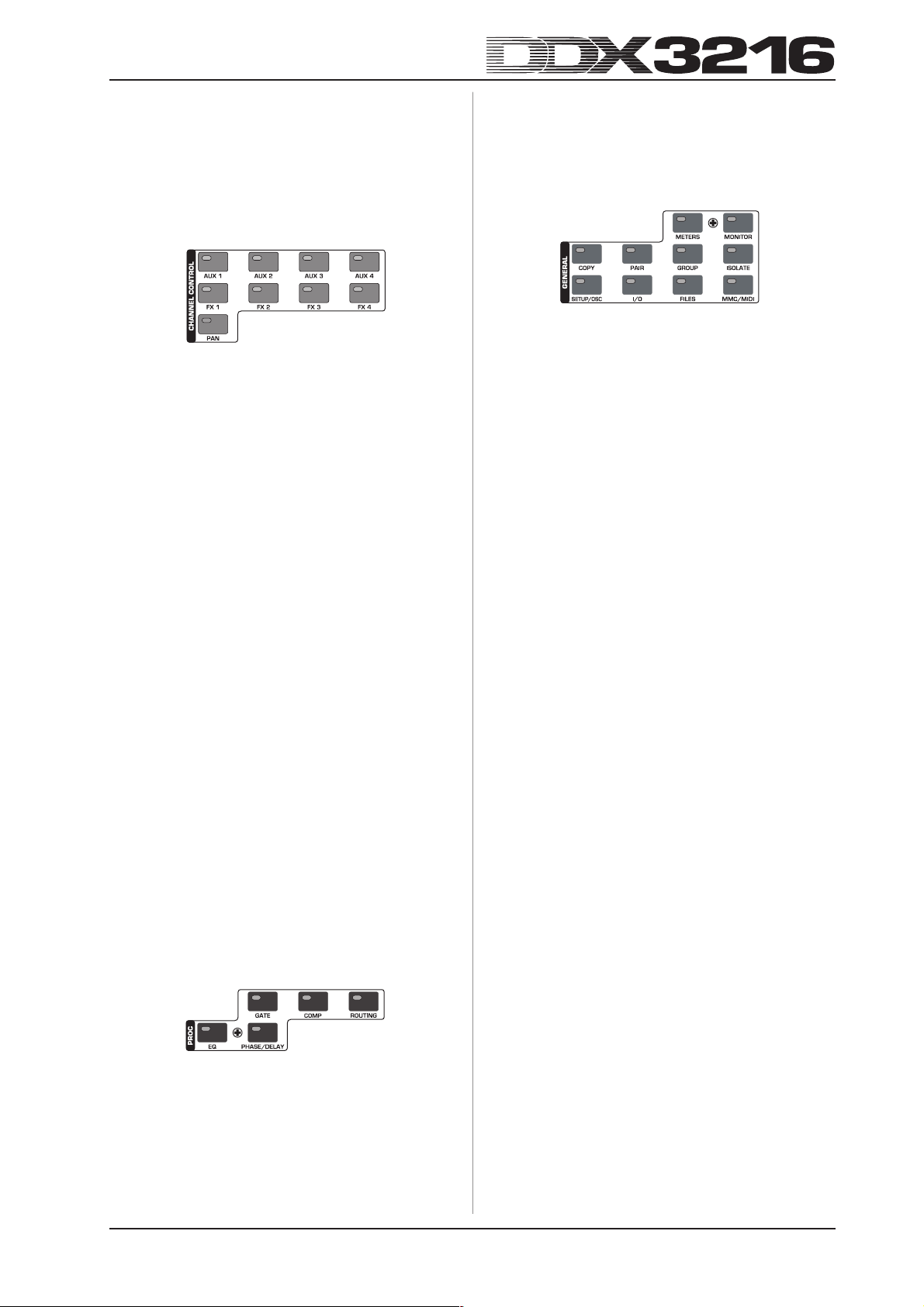
2.7.4 General bank
Fig. 2.21: General bank
Fig. 2.19: Channel control bank
The channel controller above the fader is always assigned to
the same channel as the fader below it, and can be used to
control one of nine channel parameters (channel pan, or the
send level of one of the four aux or four FX sends). The eleven
LEDs surrounding the controller indicate its current position.
The parameter assigned to the controller is selected by means
of nine dedicated switches located in the switch block in the left
console section. These switches also display the menu page for
the selected function. When the function DISPLAY FOLLOWS
CHANNEL CONTROL (PREFS page in SETUP menu) is enabled,
the first press of the CHANNEL CONTROL switch also displays
the associated menu page (send, FX 1-4 or LIB page). When this
function is off, the menu page will be displayed only by pressing
the CHANNEL CONTROL switch a second time; in this mode,
only the channel controller function will be changed. As with all
display pages, multiple presses of the CHANNEL CONTROL
switch display the available menu pages (which can also be
done with the PREVIOUS and NEXT switches to the right of the
display).
The FADER functions for the rotary control are not available
for all channels. For example, the bus outputs have no aux or
effect sends, nor do they have a pan parameter. In this case, the
LED ring around the controller will be off, and turning the controller
will have no effect. Instead, the display will read “FUNCTION
NOT AVAILABLE”.
AUX 1-4
Assigns one of the four aux sends to the channel controllers.
FX 1-4
Assigns one of the four FX sends to the channel controllers.
PAN
Assigns the channel pan to the channel controller. The channel
controller in the MAIN strip exclusively functions as BALANCE
control for the stereo mix. However, for this purpose, MAIN
CONTROL AS AUX/FX MASTER on the PREFS page in the SETUP
menu needs to be deactivated (ex works).
2.7.3 Proc(ess) bank
Fig. 2.20: Proc(ess) bank
All input channels as well as the main mix outputs are equipped
with a comprehensive set of dynamics and equalization functions.
Inputs 1-16 also have delay sections.
The signal processing in the selected channel is adjusted by
means of on-screen controls. The CHANNEL PROCESSING
switches (PROC) display the menu pages for the corresponding
functions in the selected channel: EQ, gate, compressor, phase/
delay and routing. Many of the CHANNEL PROCESSING menus
These switches access menu pages for various console
settings or to activate specific functions. In some cases, several
pages are grouped together, and you can scroll through them
with the PREVIOUS and NEXT switches or by pressing a GENERAL
switch several times.
METERS
Displays the menu page for controlling the level meters, which
are specifically described in chapter 6 ”MONITORING AND LEVEL
METERS”.
MONITOR
Display the menu page for controlling the monitor speakers via
the Control Room monitor output. This switch flashes whenever
the signal source assigned to the Control Room output is not the
stereo main mix. The monitoring functions are discussed in
chapter 6 “MONITORING AND LEVEL METERS”.
COPY
Opens the COPY dialog, in which you can exchange data
between single channels. The COPY parameters are specifically
described in chapter 7 “GROUPS, PAIRS AND COPY FUNCTIONS”.
PAIR
Opens the PAIR dialog, in which neighboring channels can be
grouped as stereo pairs. Pairing/grouping of channels is discussed
in chapter 7 “GROUPS, PAIRS AND COPY FUNCTIONS”.
GROUP
Opens the GROUP dialog, in which you can organize faders
and mutes in groups. The FADER menu shows the current mute
and fader groups. Fader and mute groups are specifically
described in chapter 7 “GROUPS, PAIRS AND COPY FUNCTIONS”.
ISOLA T E
Temporarily disables, or “isolates” all groups, but has no effect
on paired channels. The LED in the ISOLATE switch lights up, as
long as all groups are disabled. When the ISOLATE switch is
engaged, all members from one group can be set independently of
each other, for example, to re-adjust the balance between grouped
channels. When ISOLATE is turned off, all groups are re-activated,
using the new mute and fader positions as link values.
SETUP/OSC
Displays the SETUP menu for controlling the parameters word
clock, user preferences and oscillator. Details on this can be
found in chapter 12 “SETUP”.
I/O
Displays the menu pages for the input/output and multi-output
routing, S/PDIF input/output and “dither” for the digital outputs of
optional I/O modules. More on these menu pages can be found in
chapter 8.2 “I/O Routing”.
FILES
Displays the menu pages for saving, loading and deleting files,
and for updating the operating system. Details on these functions
can be found in chapter 9 “FILE MANAGEMENT”.
MMC/MIDI
Displays the menu pages for the MIDI and MMC settings (MIDI
Machine Control). For detailed information please read chapter
13 “MIDI CONTROL”.
2. CONTROL ELEMENTS AND CONNECTORS
17
 Loading...