Behringer 305 Quick Start Guide

Quick Start Guide
305 EQ/MIXER/OUTPUT
Legendary Analog Parametric EQ, Mixer and Output Module for Eurorack
Controls
(4)


 (1)
(1)
(5) |
|
(2) |
(6) |
|
|
|
|
|
(7) |
|
(3) |
(8) |
|
|
|
|
|
(9) |
|
(14) |
(10) |
|
(15) |
|
|
|
(11) |
(13) |
(12) |
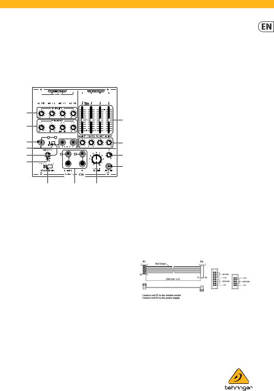
(1)MIXER INPUTS (1 / 2 / 3 / 4) – Use these jacks to route audio signals into the OUTPUT MIXER section via cables with 3.5 mm connectors. Channel 1 includes a pre-wired, normalled connection from the parametric EQ section, so the PARAMETRIC EQ output can directly enter the Channel 1 signal path just before the volume slider. If a 3.5 mm connector is inserted into the MIXER INPUT 1 jack, the EQ output is disconnected and replaced by the incoming jack signal from MIXER INPUT 1.
(2)VOLUME SLIDERS – Use these sliders for independent volume control of each input channel.
(3)PANPOT – These knobs control each channel’s placement in the stereo field.
(4)LEVEL (1 / 2 / 3 / 4) – Use these knobs to cut or boost each of the PARAMETRIC EQ’s four frequency bands.
(5)BANDWIDTH – These knobs control the width or narrowness of the parabolic filter curve for each frequency band. Higher values narrow the curve, while lower values produce a wider, gentler parabolic curve.
(6)FREQUENCY – Use these knobs to adjust the placement of each EQ filter around the center value shown just above the knob.
(7)IN – Use this input to route external signals into the PARAMETRIC EQ section via cables with 3.5 mm
connectors. The IN jack’s associated signal and clip LEDs read the input signal level when BYP is selected on the EQ/BYP sliding switch. When EQ is selected on the EQ/BYP sliding switch, the LEDs read the EQ output level.
V 1.0
(8)EQ/BYP – This sliding switch turns the PARAMETRIC EQ circuit on or off. When the switch is in the BYP position, and the EQ circuit is inactive, the signal coming in through the IN jack will be passed through unaltered to the Channel 1 mixer channel.
(9)EQ OUT (1 / 2) – Use these parallel output jacks to send the PARAMETRIC EQ section’s processed signal out for use elsewhere via cables with 3.5 mm connector. When the EQ/BYP switch is in the BYP (bypassed) position, the signal coming in through the IN jack will be duplicated at the EQ OUT outputs.
(10)MIX LEVEL – Use this knob to adjust the volume of the STANDARD OSC output before the adjusted signal is then sent to the headphone LEVEL control and the final MASTER VOLUME control.
(11)FREQ (OFF / 220 / 440 / 880) – This sliding switch turns the onboard oscillator (STANDARD OSC) on or off and chooses the oscillator’s frequency. The oscillator’s output goes to the OUTPUT MIXER section as a pre-wired parallel connection, like an additional fifth mono channel, that is blended into the mixer section’s output using the MIX LEVEL control.
(12)MASTER VOLUME – Use this knob to make final level adjustments before the mix goes to the MASTER OUTPUTS.
(13)MASTER OUTPUTS – Use these outputs to send out the final mix via separate left and right jacks via cables with either 3.5 mm or ¼” connectors. For a single mono output, use only the output labeled L/MONO.
(14)LEVEL (PHONES) – Use this knob to control the volume level for the PHONES output.
(15)PHONES – This output sends out the final mix for headphones with a 1/8” stereo connector.
Power Connection
The 305 EQ/MIXER/OUTPUT module comes with the required power cable for connecting to a standard Eurorack power supply system. Follow these steps to connect power to the module. It is easier to make these connections before the module has been mounted into a rack case.
1.Turn the power supply or rack case power off and disconnect the power cable.
 Loading...