Behringer 1004 Quick Start Guide

Quick Start Guide
OSCILLATOR MODULE 1004
Legendary 2500 Series Dual Core VCO Module for Eurorack
Controls
(1)
(2)
(3)


 (4)
(4)
(6) |
|
(7) |
(5) |
|
|
(8) |
|
(9) |
|
(10) (11) (12) (13)
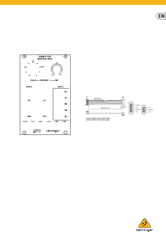
(1)COARSE FREQUENCY – Sets the frequency from 0.03 to 32 Hz in the low (LFO) range, or from 15.5 Hz to 16 kHz in the high (audio) range, depending on the Fine frequency knob setting.
(2)FINE FREQUENCY – Adjusts the frequency by a factor of ±1 octave, potentially halving or doubling the frequency at either extreme.
(3)ENABLE switch – Turns the oscillator on and off.
(4)RANGE switch – Determines whether the oscillator operates in the low (subsonic/LFO) band or the high (audio) band.
(5)WAVEFORM switches – Engage up to 5 waveforms by moving the relevant toggle switch to the left, or engage the inverse waveform by moving the switch to the right. The center position turns the waveform off. Engaging multiple switches simultaneously produces the average of all active waveforms.
(6)PW knob – Manually control the pulse width for the pulse waveform.
(7)FM 2 knob – Attenuates the signal connected to the FM
2input.
(8)PWM knob – Adjusts the modulation depth of the PMW control input.
(9)FM 1 knob – Attenuates the signal connected to the FM
1input.
(10)KYBD – Connect a keyboard or other external frequency control via 3.5 mm TS cable.
(11)FM 1/2 – Connect external voltages to modulate the frequency.
(12)PWM – Connect an external voltage to modulate the pulse width.
(13)OUT – Send the oscillator signal to other modules via 3.5 mm TS cable.
Power Connection
The unit comes with the required power cable for connecting to a standard Eurorack power supply system. Follow these steps to connect power to the module. It is easier to make these connections before the module has been mounted into a rack case.
1.Turn the power supply or rack case power off and disconnect the power cable.
2.Insert the 16-pin connector on the power cable into the socket on the power supply or rack case. The connector has a tab that will align with the gap in the socket, so it cannot be inserted incorrectly. If the power supply does not have a keyed socket, be sure to orient pin 1 (-12 V) with the red stripe on the cable.
3.Insert the 10-pin connector into the socket on the back of the module. The connector has a tab that will align with the socket for correct orientation.
4.After both ends of the power cable have been securely attached, you may mount the module in a case and turn on the power supply.
V 1.0
 Loading...