Behringer 1036 Quick Start Guide

Quick Start Guide
SAMPLE & HOLD / RANDOM VOLTAGE MODULE 1036
Legendary 2500 Series Dual Sample and Hold with Voltage Controlled Clock Module for Eurorack
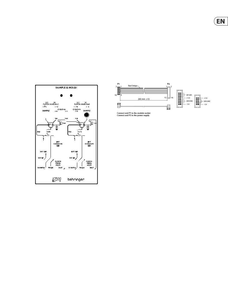
(10)EXT IN - Connect an external voltage which will be sampled and manipulated.
(11)SAMPLE - Connect an external oscillator or keyboard trigger to generate a sample command pulse.
(12)FM IN - Connect a voltage to control the clock frequency modulation of the pulse generator.
(13)OUT - Send the sample to other modules via 3.5 mm TS cable.
Controls
(1)


(2)
(3)
(4)
(5)
(6)
(7)
(8)
(9)
(10)
(11)
(12)(13)
(1)LED - Indicates that clock A or B is engaged.
(2)CLOCK FREQ - Sets the clock frequency value.
(3)CLOCK RANGE - Determines whether the value selected with the associated Clock Frequency knob is interpreted by a factor of 1/10th or x10. For example, a setting of 50 on the knob will either result in 5 Hz or 500 Hz.
(4)SAMPLE - Manually generate a sample command pulse.
(5)CLOCK ON/OFF - Engage clock A and B pulse generators independently. Clock A can be assigned to both sample and hold sections if desired.
(6)TRIG/GATE - Determines whether a short trigger or longer gate will open the sampler. In the trigger position, the positive edge of the pulse will open the sampler for about 10 ms, whereas the gate position will hold the output of the sampler open for the entire duration of the positive pulse.
(7)INT RANDOM SIG - Adjusts the level of the internal random signal generator, which can be used instead of or in addition to an external signal.
(8)EXT SIG - Attenuates the signal connected to the EXT IN jack.
(9)CLOCK FREQ MOD - Attenuates the signal connected to the FM IN jack.
Power Connection
The unit comes with the required power cable for connecting to a standard Eurorack power supply system. Follow these steps to connect power to the module. It is easier to make these connections before the module has been mounted into a rack case.
1.Turn the power supply or rack case power off and disconnect the power cable.
2.Insert the 16-pin connector on the power cable into the socket on the power supply or rack case. The connector has a tab that will align with the gap in the socket, so it cannot be inserted incorrectly. If the power supply does not have a keyed socket, be sure to orient pin 1 (-12 V) with the red stripe on the cable.
3.Insert the 10-pin connector into the socket on the back of the module. The connector has a tab that will align with the socket for correct orientation.
4.After both ends of the power cable have been securely attached, you may mount the module in a case and turn on the power supply.
Installation
The necessary screws are included with the module for mounting in a Eurorack case. Connect the power cable before mounting.
Depending on the rack case, there may be a series of fixed holes spaced 2 HP apart along the length of the case, or a track that allows individual threaded plates to slide along the length of the case. The free-moving threaded plates allow precise positioning of the module, but each plate should be positioned in the approximate relation to the mounting holes in your module before attaching the screws.
Hold the module against the Eurorack rails so that each of the mounting holes are aligned with a threaded rail or threaded plate. Attach the screws part way to start, which will allow small adjustments to the positioning while you get them all aligned. After the final position has been established,
tighten the screws down.
V 1.0
 Loading...