


Quick Start Guide
MODAMP MODULE 1005
Legendary 2500 Series Ring Modulator and VCA Module for Eurorack
Controls
(1)
(2)


 (3)
(3)
(4) |
|
|
(5) |
|
|
(9) |
|
|
|
|
|
(6) |
|
|
(12) |
(7) |
|
|
|
|
|
(8) |
|
|
|
|
|
(10) |
|
|
(13) |
|
|
|
|
(11) |
(14) |
(15) |
(16) |
(1)AMPLIFIER GAIN – This knob controls the VCA’s gain and final output volume at the OUT jack.
(2)UNMOD GAIN – This knob controls the IN A signal gain when the module is in UNMOD mode (as indicated by the UNMOD button). UNMOD mode allows the module to be used as a VCA when modulation is not required.
(3)AMPLIFIER CONTROL MODE (EXP’L/LINEAR) – This sliding switch determines whether the VCA gain response is exponential (EXP’L) or linear (LINEAR).
(4)UNMOD – Press this button to place the module into UNMOD mode. In UNMOD mode, the IN A signal passes to the OUT jack without any modulation, and the signal level is controlled by both the UNMOD GAIN and AMPLIFIER GAIN knobs. IN B does not function in UNMOD mode.
(5)MOD – Press the button to activate MOD mode. In MOD mode, the circuit combines the IN A signal and the IN B signal to produce an output signal that is a modulated combination of the two input signals.
(6)RATIO – Use this knob in MOD mode to offset the tune control voltage that is sent out through the CV B jack. This function only operates when MOD mode is selected.
(7)TUNE – Use this knob in MOD mode to control the output level of the tune control voltage sent out through both the CV A and CV B jacks. This function only operates when MOD mode is selected.
(8)IN A – This knob controls the input level for the signal coming in through the IN A jack.
(9)IN B – This knob controls the input level for the signal coming in through the IN B jack.
(10)IN A / IN B – Use these input jacks to route in audio signals for the internal modulation process via cables with
3.5mm connectors.
(11)CV A / CV B – Use these jacks to route TUNE (CV A and CV B) and RATIO (CV B offset) control voltages out to the
two VCOs that typically supply the audio signals to the IN A and IN B inputs to be modulated.
(12)CV IN – Use this jack to route in control voltage signals for remote control of the AMPLIFIER GAIN setting.
(13)MOD – Use this jack to route in a trigger signal to remotely activate MOD mode via a cable with 3.5 mm connectors.
(14)GATE – Use this input jack to route in a gate signal to turn the modulation circuit on and off via a cable with
3.5mm connectors.
(15)UNMOD – Use this jack to route in a trigger signal to remotely switch off MOD mode via a cable with 3.5 mm connectors .
(16)OUT – This jack sends out the final VCA signal via cable with 3.5 mm connectors.
V 1.0
2 MODAMP MODULE 1005
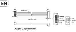
Power Connection
The MODAMP MODULE 1005 module comes with the required power cable for connecting to a standard Eurorack power supply system. Follow these steps to connect power to the module.
It is easier to make these connections before the module has been mounted into a rack case.
1.Turn the power supply or rack case power off and disconnect the power cable.
2.Insert the 16-pin connector on the power cable into the socket on the power supply or rack case. The connector has a tab that will align with the gap in the socket, so it cannot be inserted incorrectly. If the power supply does not have a keyed socket, be sure to orient pin 1 (-12 V) with the red stripe on the cable.
3.Insert the 10-pin connector into the socket on the back of the module. The connector has a tab that will align with the socket for correct orientation.
4.After both ends of the power cable have been securely attached, you may mount the module in a case and turn on the power supply.
Installation
The necessary screws are included with the module for mounting in a Eurorack case. Connect the power cable before mounting.
Depending on the rack case, there may be a series of fixed holes spaced 2 HP apart along the length of the case, or a track that allows individual threaded plates to slide along the length of the case.
The free-moving threaded plates allow precise positioning of the module, but each plate should be positioned in the approximate relation to the mounting holes in your module before attaching the screws.
Hold the module against the Eurorack rails so that each of the mounting holes are aligned with a threaded rail or threaded plate. Attach the screws part way to start, which will allow small adjustments to the positioning while you get them all aligned. After the final position has been established, tighten the screws down.
 Loading...