

Page 1
Installation and Operating instructions for
C9900-P223 and C9900-P224
Power Supply Units
Version: 1.2
Date: 2012-02-22
Page 2

Page 3

Table of contents
Table of contents
1. Foreword 2
Notes on the Documentation 2
Liability Conditions 2
Trademarks 2
Patent Pending 2
Copyright 2
State at Delivery 2
Delivery conditions 2
Description of safety symbols 3
Basic safety measures 4
Operator's obligation to exercise diligence 4
2. Product Description 5
Appropriate Use 5
Beckhoff power supply technology 5
Electrical data 6
3. Installation Instructions 7
Configuration and installation 7
Connection with the motherboard 8
Pin assignment 8
Connection with the Industrial PC 9
Pin assignment of the connector 9
External wiring 10
Cable Cross Sections 10
PC_ON and Power Status functions 10
UPS output, C9900-P224 only 11
UPS output function 11
Wiring diagram 11
Fitting the cable 12
Material for assembling the connectors 12
Assembling the connectors 12
4. Operating Instructions 13
UPS Software Components (only C9900-P224) 13
Installation on the PC 13
Help files 13
Servicing 13
Shutting down 13
Disposal 13
5. Troubleshooting 14
Beckhoff Support & Service 14
Beckhoff branches and partner companies 14
Beckhoff Headquarters 14
Beckhoff Support 14
Beckhoff Service 14
6. Appendix 15
Technical data 15
Approvals 15
FCC: Federal Communications Commission Radio Frequency Interference
Statement 15
FCC: Canadian Notice 15
C9900-P223 / C9900-P224 1
Page 4

Foreword
Foreword
Notes on the Documentation
This description is only intended for the use of trained specialists in control
and automation engineering who are familiar with the applicable national
standards. It is essential that the following notes and explanations are
followed when installing and commissioning these components.
The responsible staff must ensure that the application or use of the
products described satisfy all the requirements for safety, including all the
relevant laws, regulations, guidelines and standards.
Liability Conditions
The documentation has been prepared with care. The products described
are, however, constantly under development. For that reason the
documentation is not in every case checked for consistency with
performance data, standards or other characteristics. In the event that it
contains technical or editorial errors, we retain the right to make alterations
at any time and without warning. No claims for the modification of products
that have already been supplied may be made on the basis of the data,
diagrams and descriptions in this documentation.
Trademarks
Beckhoff®, TwinCAT®, EtherCAT®, Safety over EtherCAT®, TwinSAFE®
and XFC
Automation GmbH.
Other designations used in this publication may be trademarks whose use
by third parties for their own purposes could violate the rights of the
owners.
Patent Pending
The EtherCAT Technology is covered, including but not limited to the
following patent applications and patents:
EP1590927, EP1789857, DE102004044764, DE102007017835
with corresponding applications or registrations in various other countries.
The TwinCAT Technology is covered, including but not limited to the
following patent applications and patents:
EP0851348, US6167425 with corresponding applications or registrations in
various other countries.
Copyright
© Beckhoff Automation GmbH.
The reproduction, distribution and utilization of this document as well as the
communication of its contents to others without express authorization are
prohibited. Offenders will be held liable for the payment of damages. All
rights reserved in the event of the grant of a patent, utility model or design.
State at Delivery
All the components are supplied in particular hardware and software
configurations appropriate for the application. Modifications to hardware or
software configurations other than those described in the documentation
are not permitted, and nullify the liability of Beckhoff Automation GmbH.
Delivery conditions
In addition, the general delivery conditions of the company Beckhoff
Automation GmbH apply.
®
are registered trademarks of and licensed by Beckhoff
2 C9900-P223 / C9900-P224
Page 5
Foreword
Description of safety symbols
The following safety symbols are used in this operating manual. They are
intended to alert the reader to the associated safety instructions.
Acute risk of injury!!
DANGER
WARNING
CAUTION
Attention
Note
If you do not adhere the safety advise adjoining this symbol, there is
immediate danger to life and health of individuals!
Risk of injury!
If you do not adhere the safety advise adjoining this symbol, there is
danger to life and health of individuals!
Hazard to individuals!
If you do not adhere the safety advise adjoining this symbol, there is
obvious hazard to individuals!
Hazard to devices and environment
If you do not adhere the notice adjoining this symbol, there is obvious
hazard to materials and environment.
Note or pointer
This symbol indicates information that contributes to better understanding.
C9900-P223 / C9900-P224 3
Page 6
Foreword
Basic safety measures
Use only with Beckhoff Industrial PCs
Note
The power supply unit must only be used in conjunction with Beckhoff
Industrial PCs!
Switch off the power supply of the system during installation!
Attention
During assembly, removal and electrical wiring of the power supply unit,
the power supply of the system must be switched off in order to prevent
damage on the power supply unit and the Industrial PC.
Items of equipment that have been switched off must be secured against
being switched on again.
Do not open the power supply unit while voltage is applied!
WARNING
The supply voltage must be switched off before the power supply unit
housing is opened.
Operator's obligation to exercise diligence
Only appropriately trained staff may install the power supply unit!
CAUTION
The operator must ensure that only appropriately trained electricians deal
with installation and wiring of the power supply unit.
4 C9900-P223 / C9900-P224
Page 7

Product Description
Product Description
Appropriate Use
The C9900-P223 and C9900-P224 power supply unit provide the power
supply for Beckhoff Industrial PCs.
The C9900-P224 power supply in conjunction with a C9900-U330 b attery
pack allows the construction of an uninterruptible power supply (UPS).
Risk of explosion!
WARNING
Schematic diagram of
power supply unit wirings
Risk of explosion if other battery packs are used!
Beckhoff power supply technology
Innovative solution for
shutting down Industrial
PCs
C9900-P223 / C9900-P224 5
Industrial PCs equipped with a UPS are in actual use frequently switched
off by simply turning off the supply voltage. In this case the PC shuts down
via the battery. However, over time this reduces the service life of the
battery.
The new Beckhoff power supply technology approach addresses this
problem and now offers the user the option of switching the PC off without
the need for using the battery, thereby reducing the load on the battery.
In addition to the main switch this innovative solution uses an ON/OFF
switch for the machine. Basically, the main switch remains switched on and
provides the power supply for the PC during shutdown. Via the PC ONinput of the power supply the PC gets the command to shut down the
operating system.
Once the PC has shut down, the PC power supply unit sets the Power
Status-output (P-S) to 0, what indicates that the process is complete and
that the main voltage can be switched off. This can be done manually via a
signal lamp connection or via a contactor. With this solution the main
Page 8

Product Description
switch generally only has to be switched off if the control cabinet has to be
opened. The battery will only be used in the event of a power failure.
In order to maintain a screen display for the Industrial PC in the event of a
power failure, the C9900-P224 power supply unit is equipped with a UPS
output 27 V / 1.4 A for connecting a Control Panel with a display dimension
up to 19 inches. This enables a power failure to be visualized and
displayed to the user. Once the PC has shut down, the UPS output is
switched off.
For a detailed functional description please refer to section External wiring.
Electrical data
Input voltage: 22–30V DC/ 15A
Power output: max. 150W, depending on cooling
Output voltages: + 5V 20A
+ 12V 5A
+ 5VSB 1A
6 C9900-P223 / C9900-P224
Page 9
Installation Instructions
Installation Instructions
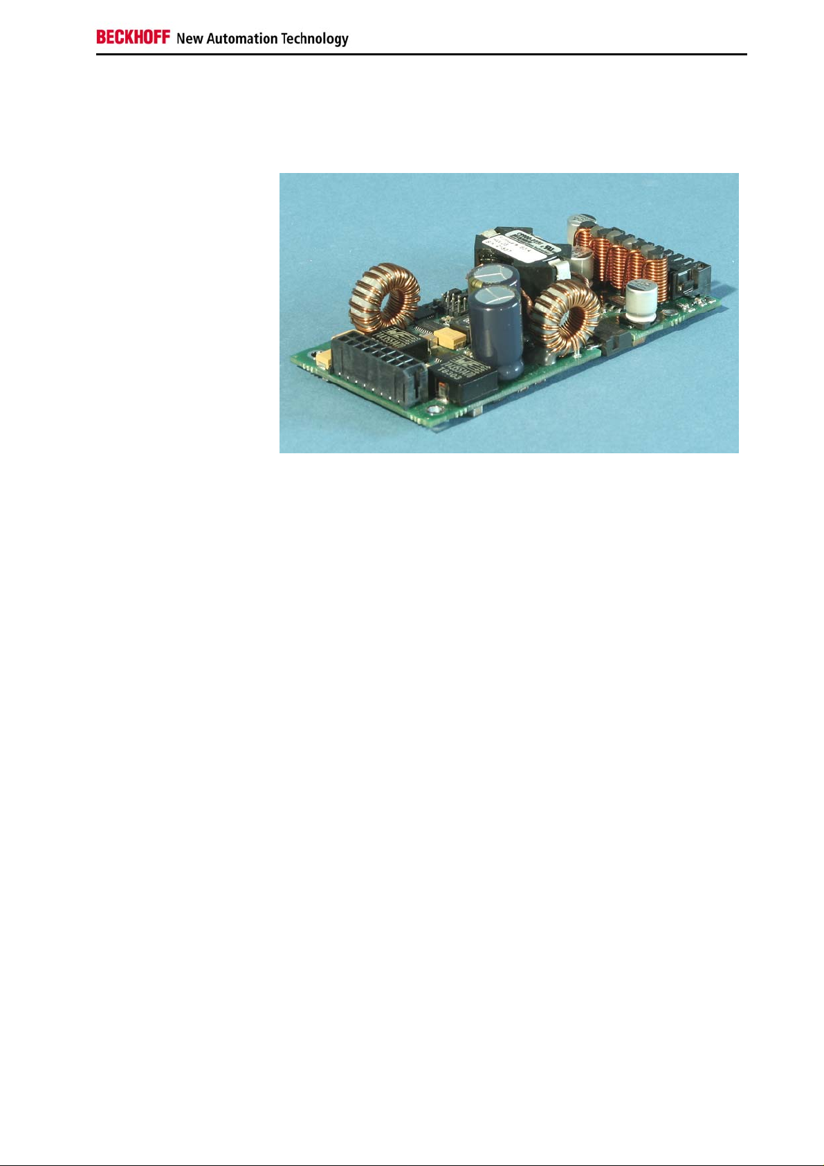
Configuration and installation
View of the power supply
unit
1
2
The power supply unit is installed at the prescribed position in the Industrial
PC.
The figure shows the supply connections for the power supply unit (1) and
the electrical connections for the motherboard (2).
C9900-P223 / C9900-P224 7
Page 10

Installation Instructions
Connection with the motherboard
Pin strips
on the output side
Connection with the
motherboard
Pin assignment of the
output connector
Signal description
The power supply unit is connected with the motherboard according to the
installation instructions of the board.
Pin assignment
Connector: MOLEX-34045-1613
Function Description
Pin Signal Pin Signal
1
2
3
4
5
6
7
8
RX
PS_ON
ATXSW
+ 12V
GND
GND
+ 5V
+ 5V
9
10
11
12
13
14
15
16
TX
Powergood
5 V Standby
+ 12V
GND
GND
+ 5V
+ 5V
RX TTL-input RS232-interface (view from power supply)
TX TTL-output RS232- interface (view from power supply)
PS_ON TTL-input voltage request from motherboard
High -> motherboard reports "stand-by"
Low -> motherboard reports "connect voltage"
Powergood TTL-output
Low -> voltages at motherboard connector not o.k.
High -> voltages at output connector o.k.
ATXSW TTL-output
Enables the Power supply to boot the Industrial PC via the ATXswitch:
Low -> motherboard logic shall open the ATX-switch
HIGH -> motherboard logic shall close the ATX-switch
GND ground
VCC +5V 20A
+12V +12V 5A
5V-Standby +5V 1A standby voltage
8 C9900-P223 / C9900-P224
Page 11
Installation Instructions
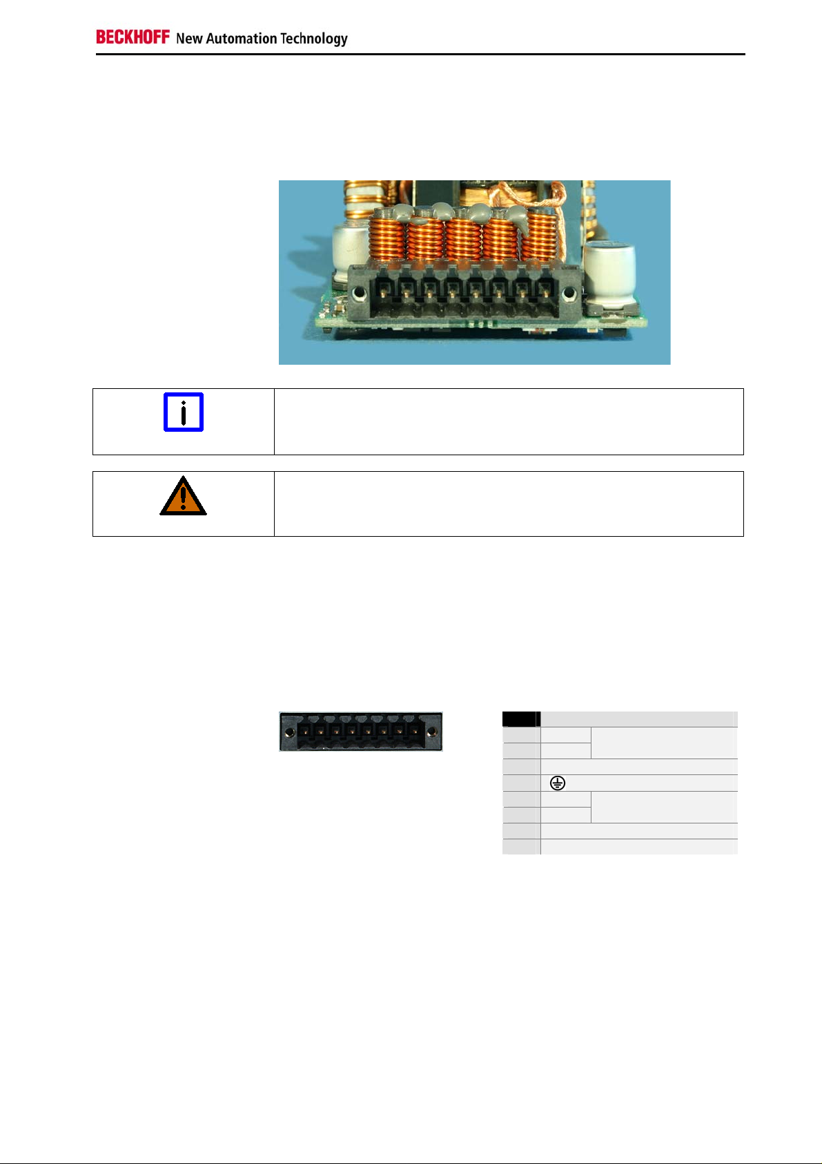
Connection with the Industrial PC
The pin strip shown on the photograph is mounted on the power supply
unit for connecting the unit with the power supply, switch, battery pack
(C9900-P224 only) and UPS output (C9900-P224 only).
Pin strips
on the input side
Uninterruptible power supply (UPS)
Note
With the C9900-P224 power supply you can realize an uninterruptible
power supply (UPS) using the battery pack C9900-U330.
Risk of explosion!
Risk of explosion if other battery packs are used!
WARNING
A Control Panel can be connected to the UPS output of the C9900-P224.
The maximum current loading is 1.4 A.
Pin assignment of the connector
The power supply and the external circuit for switching the Industrial PC on
and off are connected via the 8-pole plug connector .
Pin assignment for
connecting the switch, the
power supply and the
battery pack (optional)
1 2 3 4 5 6 7 8
Pin Function
1
-
2
+
3
UPS+ (only C9900-P224)
4
5
-
6
+
7
PC_ON
8
Power-Status
Battery Pack
(only C9900-P224)
24 V DC
Power Supply
C9900-P223 / C9900-P224 9
Page 12

Installation Instructions
The external wiring consists of the connection of the power supply, the
External wiring
battery pack (only C9900-P224) and the connection of customized
components for shutting down the PC.
The external wiring occurs according to the wiring diagram, see chapter
Wiring diagram.
Cable Cross Sections
Note cable cross sections,
avoid voltage drop!
For the connection of the power supply, wiring with a cable-cross-section
of 1.5 mm
With bigger distances between voltage source and PC, you take the
voltage drop as a function of the cable-cross-section as well as voltage
fluctuations of your distribution voltage into account, so that is secured that
the voltage doesn't fall under 22 V at the power supply.
Insert fuse
2
must be used.
Attention
The power supply must be protected with 16 A.
PC_ON and Power Status functions
Attention
If the PC_ON input is connected to 24 V via a switch, the PC shuts
down according to the rules. The PC_ON signal is inverted, i.e. the
PC shuts down if the 24 V connection is live.
If the PC_ON input is NOT connected by the user, the PC can be
booted in the familiar way by connecting the supply voltage and shut
down via the battery by switching off the supply voltage.
Service life of the rechargeable battery
This procedure significantly reduces the service life of the rechargeable
battery and should therefore not be used.
Once the PC has shut down, the Power Status output is switched
from 24 V to 0 V. Via this output a signal lamp can be connected or a
contactor for de-energizing the whole system. The maximum load for
the Power Status output is 0.5 A and a suitable fuse should be
provided.
10 C9900-P223 / C9900-P224
Page 13
Installation Instructions
UPS output, C9900-P224 only
In order to maintain a screen display for the PC in the event of a power
failure, the C9900-P224 power supply unit is equipped with a UPS output
for connecting a Control Panel. The maximum load for the output is 1.4 A.
The UPS output is located on the power supply unit adjacent to the mains
plug (see also section Product Description.
UPS output function
The 27 V DC connection at the UPS output is live even after a power
failure. The maximum load is 1.4 A (C9900-P224 only).
Once the PC has been de-energized via the UPS software, the UPS
output is switched to 0 V. Any connected panel is thus switched off,
and total discharge of the rechargeable battery is prevented.
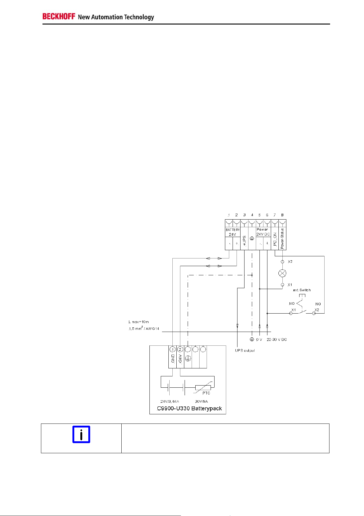
Wiring diagram
Wiring according to the wiring diagram.
The circuit of PC_ON and Power-Status is symbolical.
Wiring diagram external
switch and power supply
Connection of the Battery Pack and UPS Output
Note
C9900-P223 / C9900-P224 11
Connection of the Battery Pack and UPS Output only in combination with
C9900-P224 power supply.
Page 14

Installation Instructions
Fitting the cable
Wiring in accordance with
wiring diagram
Fit the cables for the power supply of the Industrial PC, the connection of
the battery pack as well as the connection of the power-switch in
accordance with the wiring diagram, using the included material for
assembling the connectors.
Material for assembling the connectors
Material for assembling the
connectors
Plug connector 8-pole, Strain
relief housing with lacing cord
Conductive cross-section The connector is specified for 16 A and can lift conductive cross-sections
Fitting the connector to the
cable
Assembling the connectors
until 1.5 mm
So the connector is fitted to the cable:
1. Strip insulation from the cable ends (Length of stripped conductor
2
.
is 8 – 9 mm).
2. Screw together the cable ends in the 8-pole plug connector in
accordance with wiring diagram.
Applying the strain relief
Thread the lacing cord into that
lower part of the strain relief
housing.
Putting in the plug
connector
Fixing the upper part of the
strain relief housing
Put the plug connector into that
lower part of the strain relief
housing.
Tighten the lacing cord and pinch off
the plastic strap.
Fix the upper part of the strain relief
housing by snapping it onto the
lower part.
12 C9900-P223 / C9900-P224
Page 15

Operating Instructions
Operating Instructions
UPS Software Components
(only C9900-P224)
Installing the UPS driver
software
For operating the power supply unit as a UPS, the UPS driver software and
the associated UPS driver must be installed on the Industrial PC.
On delivery of the Beckhoff Industrial PC with operating system the
software is already installed. Should the software not be installed on your
PC, the drivers can be installed from the driver CD provided.
Installation on the PC
Installation To install the UPS driver software, execute file
Beckhoff_UPS_vx.xx.xx.exe from the subdirectory of UPS\… from the
CD provided on the Industrial PC (Driver-archive for the Industrial-PC,
C9900-S700-xxxx).
The program is self-extracting and will guide the user through the
installation routine.
Help files
Beckhoff Information
System
The driver software comes with a detailed help function.
The help files can be called up either directly from the configuration register
by clicking the Help button, or under via Start > Programs > Beckhoff >
UPS software components.
Servicing
The power supply unit is maintenance-free.
Shutting down
Disposal
Dismantling the case
Observe national
electronics scrap
regulations
The device must be fully dismantled in order to dispose of it. The housing
can be sent for metal recycling.
Electronic parts must be disposed of in accordance with national
electronics scrap regulations.
C9900-P223 / C9900-P224 13
Page 16

Troubleshooting
Troubleshooting
In the event of a fault contact your Beckhoff Service.
Beckhoff Support & Service
Beckhoff and their partners around the world offer comprehensive support
and service, guaranteeing fast and competent assistance with all questions
related to Beckhoff products and system solutions.
Beckhoff branches and partner companies
Please contact your Beckhoff branch office or partner company for local
support and service on Beckhoff products!
The contact addresses for your country can be found in the list of Beckhoff
branches and partner companies: www.beckhoff.com
You will also find further documentation
for Beckhoff components there.
Beckhoff Headquarters
Beckhoff Automation GmbH
Eiserstraße 5
33415 Verl
Germany
Phone:
Fax: +49(0)5246/963-198
e-mail: info@beckhoff.com
+49(0)5246/963-0
Beckhoff Support
Beckhoff offers you comprehensive technical assistance, helping you not
only with the application of individual Beckhoff products, but also with wideranging services:
worldwide support
design, programming and commissioning of complex automation
systems
training program for Beckhoff system components
Hotline:
Fax: +49(0)5246/963-9157
e-mail: support@beckhoff.com
+49(0)5246/963-157
Beckhoff Service
The Beckhoff service center supports you in all matters of after-sales
service:
on-site service
repair service
spare parts service
hotline service
Hotline:
Fax: +49(0)5246/963-479
e-mail: service@beckhoff.com
Quote the project number If servicing is required, please quote the project number of your product.
+49(0)5246/963-460
14 C9900-P223 / C9900-P224
Page 17

Appendix
Appendix
Technical data
Electrical data Input voltage: 22-30V DC/ 15A
Power output: max. 150W , depending on cooling
Output voltages: see section Electrical data
Dimensions Dimensions (W x H x D): 50 x 25 x 104 mm
Weight: 120 g
Do not use the power
supply unit in areas of
explosive hazard
Environmental conditions Ambient temperature: 0 to 55°C
Shock resistance
The power supply unit must not be used where there is a risk of
explosion.
The following conditions must be observed during operation:
Atmospheric humidity: Maximum 95%, non-condensing
Sinusoidal vibration
(EN 60068-2-6):
58 to 500 Hz: 0.5 G (~ 5 m/ s
Impact
(EN 60068-2-27/ -29):
10 to 58 Hz: 0.035 mm
5 G (~ 50 m/ s²), duration: 30 ms
2
)
EMC compatibility Resistance to interference: according to EN 61000-6-2
Emission of interference: according to EN 61000-6-4
Transport and storage The same values for atmospheric humidity and shock resistance are to be
observed during transport and storage as in operation. The shock
resistance during transport can be improved by appropriate packaging of
the power supply unit. The ambient temperature during storage and
transport must be between -20°C and +65°C.
Approvals
FCC: Federal Communications Commission
Radio Frequency Interference Statement
FCC Approval for USA This equipment has been tested and found to comply with the limits for a
Class A digital device, pursuant to Part 15 of the FCC Rules. These limits
are designed to provide reasonable protection against harmful interference
when the equipment is operated in a commercial environment. This
equipment generates, uses, and can radiate radio frequency energy and, if
not installed and used in accordance with the instruction manual, may
cause harmful interference to radio communications. Operation of this
equipment in a residential area is likely to cause harmful interference in
which case the user will be required to correct the interference at his own
expense.
FCC: Canadian Notice
FCC Approval for Canada This equipment does not exceed the Class A limits for radiated emissions
as described in the Radio Interference Regulations of the Canadian
Department of Communications.
C9900-P223 / C9900-P224 15
 Loading...