

Page 1

Bus coupler with RS485 interface
BK8000
Technical Documentation
Version 1.2
2006-10-30
Page 2

Contents
Contents
1. Foreword 3
Notes on the documentation 3
Liability Conditions 3
Delivery conditions 3
Copyright 3
Safety Instructions 4
State at Delivery 4
Description of safety symbols 4
2. Basic information 5
The Beckhoff bus terminal system 5
The interfaces 7
Power supply 7
Power supply to the power contacts 7
Power contacts 7
RS 485 Connection 8
K-bus contacts 8
Supply isolation 8
The operating modes of the bus coupler 9
Mechanical construction 10
Electrical data 10
The peripheral data in the process image 12
Starting operation and diagnostics 14
3. RS 485 Coupler BK8000 16
System presentation 16
The media: plugs and cable 17
Data communication 18
4. Appendix 22
Sample arrangement of a process image in the bus coupler 22
Representation of analog signals in the process image 24
5. Support and Service 26
Beckhoff's branch offices and representatives 26
Beckhoff Headquarters 26
2 BK8000
Page 3

Foreword
Foreword
Notes on the documentation
This description is only intended for the use of trained specialists in control and automation engineering
who are familiar with the applicable national standards. It is essential that the following notes and
explanations are followed when installing and commissioning these components.
Liability Conditions
The responsible staff must ensure that the application or use of the products described satisfy all the
requirements for safety, including all the relevant laws, regulations, guidelines and standards.
The documentation has been prepared with care. The products described are, however, constantly under
development. For that reason the documentation is not in every case checked for consistency with
performance data, standards or other characteristics. None of the statements of this manual represents a
guarantee (Garantie) in the meaning of § 443 BGB of the German Civil Code or a statement about the
contractually expected fitness for a particular purpose in the meaning of § 434 par. 1 sentence 1 BGB. In
the event that it contains technical or editorial errors, we retain the right to make alterations at any time
and without warning. No claims for the modification of products that have already been supplied may be
made on the basis of the data, diagrams and descriptions in this documentation.
Delivery conditions
In addition, the general delivery conditions of the company Beckhoff Automation GmbH apply.
Copyright
©
This documentation is copyrighted. Any reproduction or third party use of this publication, whether in
whole or in part, without the written permission of Beckhoff Automation GmbH, is forbidden.
BK8000 3
Page 4
Foreword
Safety Instructions
State at Delivery
All the components are supplied in particular hardware and software configurations appropriate for the
application. Modifications to hardware or software configurations other than those described in the
documentation are not permitted, and nullify the liability of Beckhoff Automation GmbH.
Description of safety symbols
The following safety symbols are used in this documentation. They are intended to alert the reader to the
associated safety instructions..
This symbol is intended to highlight risks for the life or health of personnel.
Danger
This symbol is intended to highlight risks for equipment, materials or the
Attention
environment.
This symbol indicates information that contributes to better understanding.
i
Note
4 BK8000
Page 5

Basic information
Basic information
Up to 64 bus terminals
each with 2 I/O channels
for any form of signal
Decentralized wiring of the
I/O level
IPC as control unit
Bus couplers for all current
bus systems
Standard C rail assembly
Modularity
Display of channel status
The K-bus
End terminal
The Beckhoff bus terminal system
The bus terminal system is the universal connecting link between a
fieldbus system and the sensor/actor level. A unit consists of a bus coupler,
which is the interface to the fieldbus, and up to 64 electronic terminals, of
which the last is an end terminal. Terminals, each with two I/O channels,
are available for any form of technical signal and can be combined as
desired. The various types of terminal are all constructed in the same way,
so that the planning costs are kept extremely low. The height and depth of
the construction are calculated for compact terminal cabinets.
Fieldbus technology makes it possible to use compact control
architectures. The I/O level does not need to be taken right up to the
control unit. Sensors and actors can be connected decentrally with minimal
lengths of cable. You can position the control unit at any convenient
location in the installation. Using an industrial PC as control unit makes it
possible to implement the operating and monitoring element as part of the
control hardware, so the control unit can be located on an operating desk,
control point or similar. The bus terminals constitute the decentralized
input/output level of the control unit in the switch cabinet and its
subordinate terminal cabinets. As well as the sensor/actor level, the power
unit of the equipment is also controlled via the bus system. The bus
terminal replaces a conventional terminal as the cabling level in the switch
cabinet; the switch cabinet can be made smaller.
The Beckhoff bus terminal system combines the advantages of a bus
system with the functionality of compact terminals. Bus terminals can be
used on all current bus systems and serve to reduce the diversity of parts
in the control unit, while behaving like the conventional standard units for
the relevant bus system and supporting the entire range of functionality of
the bus system.
The simple and compact assembly on a standard C rail, and the direct
cabling of actors and sensors without cross connections between the
terminals, serve to standardize the installation, as does the uniformly
designed labeling.
The small size and great flexibility of the bus terminal system mean that
you can use it anywhere that you could use a terminal and use any type of
connection – analog, digital, serial or direct sensors.
The modular construction of the terminal row, using bus terminals with
various functions, limits the number of unused channels to at most one per
function. Two channels to a terminal is the optimum solution for the number
of unused channels and the cost per channel. The possibility of using
power input terminals to provide separate power supplies also helps to
minimize the number of unused channels.
The integrated light-emitting diodes close to the sensor/actor indicate the
status of each channel.
The K-bus is the path taken by data within the terminal row. The bus
coupler carries the K bus through all the terminals by means of six contacts
on the side walls of the terminals, and the end terminal terminates the K
bus. The user does not need to know anything about the function of the K
bus or the internal operation of terminals and bus couplers. There are
numerous software tools available which provide for convenient planning,
configuration and operation.
BK8000 5
Page 6
Basic information
Power input terminals
for separately powered
groups
Three power contacts pass the operating power to the following terminals.
You can use power input terminals to subdivide the terminal row as desired
into groups, each with a separate power supply. These power input
terminals are not taken into account for addressing the terminals, you can
insert them at any position along the terminal row.
You can install up to 64 terminals on a terminal row, including power input
terminals and the end terminal.
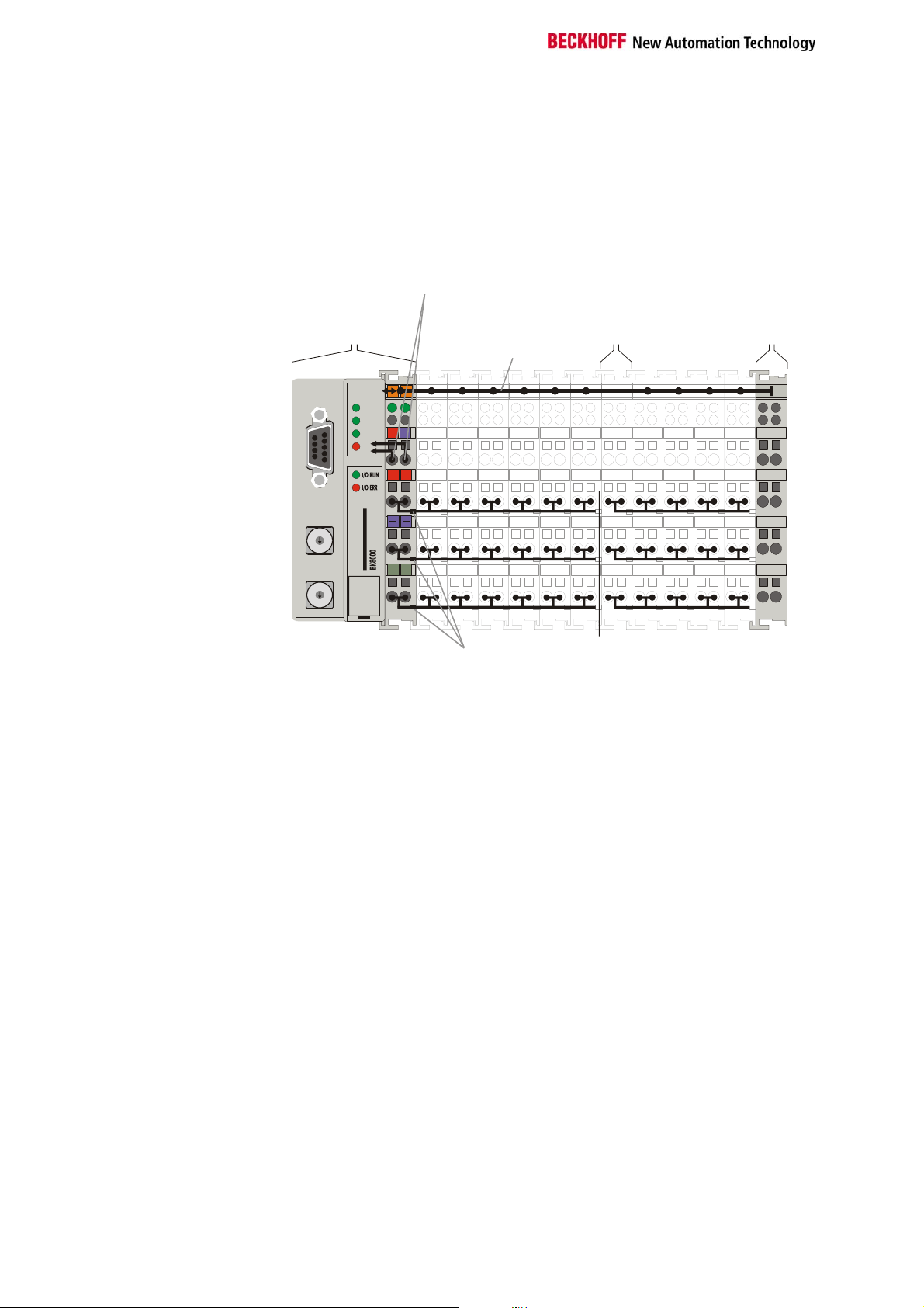
The principle of the bus
terminal
RS485
bus coupler
BK8000
Power supply
for the
bus coupler
K-Bus
Potential
input
terminal
Bus end
terminal
Bus couplers for various
fieldbus systems
0201
WD
RX
24V
0V
TX
ERR
++
BECKHOFF
PE PE
Power
contacts
Potential
isolation
X1
9
8
7
6
X10
9
8
7
6
RS 485
0
1
2
3
4
5
0
1
2
3
4
5
You can use a variety of bus couplers to attach the electronic terminal row
quickly and easily to the various fieldbus systems, and you can also
subsequently convert to a different fieldbus system. The bus coupler deals
with all the necessary monitoring and control tasks for operating the
attached bus terminals, indeed all the operation and configuration of the
bus terminals is carried out via the bus coupler. The fieldbus, K bus and I/O
level are electrically isolated.
If the exchange of data across the fieldbus is temporarily interrupted, logic
states are preserved, digital outputs are cleared and analog outputs revert
to a reset value which can be individually configured for each output when
the equipment is set up.
6 BK8000
Page 7
Basic information
The interfaces
There are six ways of making a connection to a bus coupler. These
interfaces are designed as plug connections and spring terminals.
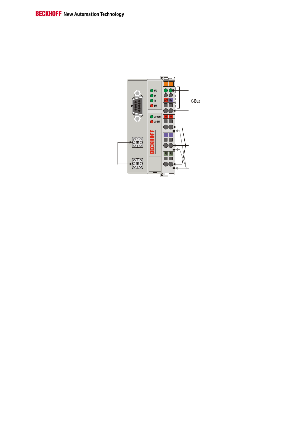
The RS485 coupler
BK8000
RS 485
Power LEDs
Bus coupler/power contacts
24 V DC on the topmost
terminals
Lower 3 terminal pairs for
power input
maximum 24 V
maximum 10 A
Spring contacts at the side
RS 485
Power supply bus coupler
24 V DC/GND
X1
Input
Address
Selector
X10
BK 8000
power contacts
power contacts
Power supply
The bus couplers need an operating power of 24 V DC which is connected
via the topmost spring terminals, labeled "24 V” and "0 V”. This power
supply serves not only the electronic components of the bus coupler but
(via the K bus) also the bus terminals. The power supply of the bus coupler
circuitry and that of the K-bus (Terminal bus) are electrically isolated from
the voltage of the field level.
Power supply to the power contacts
The six lower connections with spring terminals can be used to supply
power to the peripherals. The spring terminals are connected in pairs to the
power contacts. The power supply to the power contacts has no
connection to the power supply of the bus couplers. The power input is
designed to permit voltages up to 24 V. The pair-wise arrangement and the
electrical connection between the feed terminal contacts makes it possible
to loop through the wires connecting to different terminal points. The load
on the power contact may not continuously exceed 10 A. The current
capacity between two spring terminals is the same as the capacity of the
connecting wires.
Power contacts
On the right-hand side face of the bus coupler are three spring contacts
which are the power connections. The spring contacts are recessed in slots
to prevent them from being touched. When a bus terminal is connected,
the blade contacts on the left-hand side of the bus terminal are connected
to the spring contacts. The slot and key guides at the top and bottom of the
bus couplers and bus terminals ensure reliable location of the power
contacts.
BK8000 7
Page 8
Basic information
9 pole Sub-D female
connector strip
6 contacts at the side
3 supply groups:
fieldbus
K-bus
peripheral level
Setting up the power levels
in the bus terminal system
RS 485 Connection
There is a recessed front surface on the left-hand side. A 9-pole Sub-D
connector can be plugged in here. A detailed description of the RS485
interface can be found in a further part of this manual (chapter entitled 'The
media: plugs and cable').
K-bus contacts
The connections between the bus coupler and the bus terminals are
effected by gold contacts at the right-hand side of the bus coupler. When
the bus terminals are plugged together, these gold contacts automatically
complete the connection to the bus terminals. The K bus is responsible for
the power supply to the electronic components of the K bus in the bus
terminals, and for the exchange of data between the bus coupler and the
bus terminals. Part of the data exchange takes place via a ring structure
within the K bus. Disengaging the K bus, for example by pulling on one the
bus terminals, will break this circuit so that data can no longer be
exchanged. However, there are mechanisms in place which enable the bus
coupler to locate the interruption and report it.
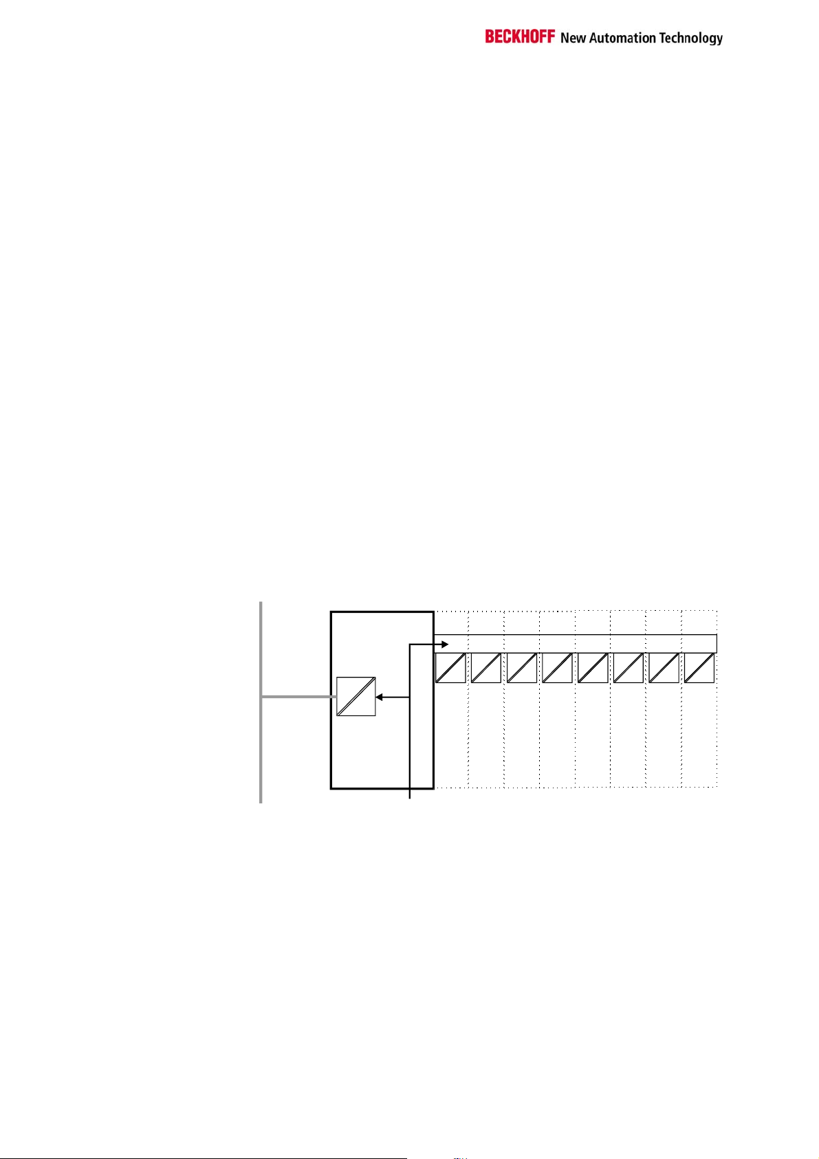
Supply isolation
The bus couplers operate with three independent supplies. The input
power supplies the electrically isolated K-bus circuitry in the bus coupler
and the K-bus itself. The power supply is also used to generate the
operating power for the fieldbus.
Note: All the bus terminals are electrically isolated from the K bus, so that
the K-bus is completely electrically isolated.
Bus terminalsBus coupler
Terminal bus
Field bus
Periphery level
24 V DC
8 BK8000
Page 9

Basic information
Start-up behavior of the bus
coupler
The operating modes of the bus coupler
When it is first switched on the bus coupler carries out a self-test to check
the functions of its components and the communications of the K bus, and
while this is going on the red I/O LED will flash. When the self-test has
been completed successfully, the bus coupler will begin to test the
attached bus terminals (the "bus terminal test”) and read in the
configuration from which it constructs an internal structure list, which is not
accessible from outside. If an error occurs the bus coupler will enter the
operating mode "STOP”. If the start-up sequence is completed without
errors the bus coupler will enter the mode "fieldbus start”.
The bus coupler reports the error to the master by means of the Profibus
diagnostics. Clearing the error returns the bus coupler to its normal
operating mode.
BK8000 9
Page 10

Basic information
Mechanical construction
The Beckhoff bus terminal system is remarkable for its compact
construction and high degree of modularity. When you design the
installation you will need to plan for one bus coupler and some number of
bus terminals. The dimensions of the bus couplers do not depend on the
fieldbus system. If you use large plugs, for example like some of the bus
plugs used for the Profibus, they may protrude above the overall height of
the cabinet.
Dimensions of a bus
coupler
RS 485
X1
X10
BK 8000
The overall width of the construction is the width of the bus coupler,
including the bus end terminal, plus the width of the installed bus terminals.
The bus terminals are 12 mm or 24 mm wide, depending on their function.
Depending on the gauge of cables used the overall height of 68 mm may
be overstepped by about 5 mm to 10 mm by the cables at the front.
Assembly and connections
It takes only a slight pressure to latch the bus coupler and the various bus
terminals onto a supporting 35mm C rail and a locking mechanism then
prevents the individual housings from being removed. You can remove
them without effort if you first release the latching mechanism by pulling the
orange tab. You should carry out work on the bus terminals and the bus
coupler only while they are switched off: if you plug or unplug components
while the power is on you may briefly provoke some undefined state (and,
for instance, reset the bus coupler).
You can attach up to 64 bus terminals in series on the right-hand side of
the bus coupler. When you assemble the components, make sure that you
mount the housings so that each slot comes together with the
corresponding key. You cannot make any functional connections merely by
pushing the housings together along the supporting track. When they are
correctly mounted there should be no appreciable gap between the
adjacent housings.
The right-hand side of a bus coupler is mechanically similar to a bus
terminal. There are eight connections on the top which can be used to
connect to thick-wire or thin-wire lines. The connection terminals are spring
loaded. You open a spring terminal by applying a slight pressure with a
screwdriver or other pointed tool in the opening above the terminal and you
can then insert the wire into the terminal without any obstruction. When you
release the pressure the terminal will automatically close and hold the wire
securely and permanently.
10 BK8000
Page 11

Basic information
Insulation test
PE power contacts
Current consumption on the
K-Bus
The connection between bus couplers and bus terminals is automatically
effected by latching the components together. The K bus is responsible for
passing data and power to the electronic components of the bus terminals.
In the case of digital bus terminals, the field logic receives power via the
power contacts. Latching the components together has the effect that the
series of power contacts constitutes a continuous power track. Please refer
to the circuit diagrams of the bus terminals: some bus terminals do not loop
these power contacts through, or not completely (e.g. analog bus terminals
or 4-channel digital bus terminals). Each power input terminal interrupts the
series of power contacts and constitutes the beginning of a new track. The
bus coupler can also be used to supply power to the power contacts.
The power contact labeled "PE” can be used as protective earth or ground.
This contact stands proud for safety reasons and can carry short-circuit
currents of up to 125 A. Note that in the interests of electromagnetic
compatibility the PE contacts are capacitively connected to the supporting
track. This may lead to spurious results and even damage to the terminal
when you test the insulation (e.g. insulation test for breakdown using a
230 V mains supply to the PE line). You should therefore disconnect the
PE line on the bus coupler while you carry out insulation tests. You can
disconnect other power supply points for the duration of the test by drawing
the power supply terminals out from the remaining row of terminals by at
least 10mm. If you do this, there will be no need to disconnect the PE
connections.
The protective earth power contact ("PE”) may not be used for any other
connections.
Electrical data
The electrical data of the RS 485 bus coupler is listed in this chapter. The
bus coupler is set to a baud rate of 38400 baud. Addresses from 0 to 99
can be set by means of two address selectors on the coupler. The
following table provides an overview of all data.
Technical data BK8000
Voltage supply
Input current
Output current K-Bus
Number of bus terminals
Digital peripheral signals
Analog peripheral signals
Maximum number of bytes
Station adress
Baud rate
Power contact voltage
Power contact current load
Dielectric strength
Weight approx.
Operating temperature
Storage temperature
Relative humidity
Vibrations/shock resistance
EMC resistance burst / ESD
Installation position
Type of protection
For operation of the K-bus electronics, the bus terminals require energy
from the K-bus that is supplied by the bus coupler. Refer to the catalog or
the corresponding data sheets of the bus terminals for details of the K-bus
24 V DC (20 ...29 V DC)
70 mA + (total K-Bus current)/4
500 mA max.
1750 mA max.
64
256 inputs/outputs
128 Ein-/ Ausgänge
512 Byte I and 512 Byte O
selectable up to 99 via DIP switches
38400 Baud
24 V DC / AC
10 A
500 Veff (Power contact / supply voltage)
170g
0°C ... +55°C
-20°C ... +85°C
95%, no condensation
conforms to IEC 68-2-6 / IEC 68-2-27
conforms to EN 50082 (ESD, Burst) / EN 50081
any
IP20
BK8000 11
Page 12

Basic information
current consumption. In doing so, pay attention to the maximum output
current of the bus coupler that is available for powering the bus terminals.
Using a special power supply terminal (KL9400), power can be fed back
into the K-bus at any chosen point. If you wish to use a power supply
terminal, please contact Beckhoff’s technical support.
Digital signals
(bit-oriented)
Analog signals
(byte-oriented)
Special signals and
interface
Default assignment of
inputs and outputs to the
process image
The peripheral data in the process image
When the bus coupler is first switched on it determines the configuration of
the attached input/output terminals and automatically assigns the physical
slots of the input/output channels to the addresses in the process image.
The bus coupler sets up an internal list of assignments in which each of the
input and output channels has a specific position in the process image. A
distinction is made here between input and output and between bit-oriented
(digital) and byte-oriented (analog, or complex) signal processing.
It also forms two groups, whereby one contains only inputs and the other
only outputs. In each group, the byte-oriented channels take the lowest
addresses, in ascending order, and these are then followed by the bitoriented channels.
Digital signals are bit-oriented. This means that one bit of the process
image is assigned to each digital channel. The bus coupler sets up a block
of memory containing the current input bits and arranges to immediately
write out the bits from a second block of memory which belongs to the
output channels.
The precise assignment of the input and output channels to the process
image of the control unit is explained in detail in the Appendix by means of
an example.
The processing of analog signals is always byte-oriented and analog input
and output values are stored in memory in a two-byte representation. The
values are held as "SIGNED INTEGER” or "twos-complement”. The digit
"0” represents the input/output value "0V”, "0mA” or "4mA”. When you use
the default settings, the maximum value of the input/output value is given
by "7FFF” hex. Negative input/output values, such as -10V, are
represented as "8000” hex and intermediate values are correspondingly
proportional to one another. The full range of 15-bit resolution is not
realized at every input/output level. If you have an actual resolution of 12
bits, the remaining three bits have no effect on output and are read as "0”
on input. Each channel also possesses a control and status byte in the
lowest value byte. If the control/status byte is mapped in the control unit
has to be configured in the master configuration software. An analog
channel is represented by 2 bytes user data in the process image.
A bus coupler supports bus terminals with additional interfaces, such as
RS485, RS485, incremental encoder, etc.. These signals can be regarded
in the same way as the analog signals described above. A 16-bit data
width may not be sufficient for all such special signals; the bus coupler can
support any data width.
When the bus coupler is first switched on it determines the number of
attached bus terminals and sets up a list of assignments. This list
distinguishes between analog channels and digital channels and between
input and output; which are grouped separately. The assignments begin
immediately to the left of the bus coupler. The software in the bus coupler
creates the assignment list by collecting the entries for the individual
channels one at a time, counting from left to right.
12 BK8000
Page 13

Basic information
These assignments distinguish four groups:
Function type of the channel Assignment level
1.
2.
3.
4
Analog outputs byte-wise assignment
Digital outputs bit-wise assignment
Analog inputs byte-wise assignment
Digital inputs bit-wise assignment
Analog inputs/ouputs are representative of other complex multi-byte signal
bus terminals (RS485, SSI sensor interface, ...)
Overview of the subdivision of the process image in the bus coupler:
Output data in the bus
coupler
O0
...
byte-oriented data
...
Ox
Ox+1
bit-oriented data
Ox+y
Input data in the bus
coupler
I0
...
byte-oriented data
...
Ix
Ix+1
...
bit-oriented data
...
Ix+y
The way from I/Os to the
process image in the
application software
The bus coupler automatically assigns the I/Os of the terminals to the
process image in the RS485 communication protocol. These allocations
can be modified with the Beckhoff KS2000 configuration software. Various
mapping parameters (e.g. Motorola/Intel format) can be set in the bus
coupler.
Data consistency
Data which contains no contradictions is said to be consistent. The
following consistency is required here: 1. The high byte and low byte of an
analog value (word consistency), 2. The control/status byte and the
corresponding parameter word for accessing the register. The interaction
of the peripherals with the control unit means that data can initially be
guaranteed consistent only within an individual byte: the bits which make
up a byte are read in together, or written out together. Byte-wise
consistency is quite adequate for processing digital signals but is not
sufficient for transferring values longer than eight bits, such as analog
values. The various bus systems guarantee consistency to the required
length. It is important to use the appropriate procedure for importing this
consistent data from the master bus system to the control unit. The
protocol for communication with the BK8000 always exchanges the
coupler's complete process image, thus ensuring data consistency.
Processing complex signals
All byte-oriented signal channels such as RS232, RS485 and incremental
encoder, can use byte lengths greater than two. Apart from the actual
difference in length, the procedure is always comparable with that for
analog signals
BK8000 13
Page 14

Basic information
Starting operation and diagnostics
When the bus coupler is first switched on it at once checks the attached
configuration. A correct start-up procedure is indicated by the red LED "I/O
ERR” going out. If this LED flashes, this indicates a fault somewhere in the
terminals. You can determine the actual error code by observing the speed
of flashing and number of flashes. This will enable you to clear the fault
quickly.
The diagnostic LEDs
The bus coupler has two groups of LEDs to provide a status display. The
top group of 4 LEDs indicates the status of the respective field bus. In the
case of the BK8000, various data transfer communication states are
displayed.
There are two further green LEDs on the top right side of the bus coupler to
display the supply voltage. The left LED displays the bus coupler's 24 V
power supply. The right LED signals the power supply to the Power
contacts.
Local errors
Two LEDs, the "I/O LEDs”, which are situated below the fieldbus status
LEDs described above, are used to display the operating mode of the bus
terminals and the connection to these bus terminals. The green LED lights
up to indicate error-free operation, where "error-free” implies that
communication with the fieldbus system is also operating correctly. The red
LED flashes at two different rates to indicate a fault, whereby the specific
error is encoded in the pattern of flashes, as follows.
Flashing code
Fast flashingq
First slow sequence
Second slow sequence
Start of the error code
Error code
Error argument
Error code Error argument Description
1 pulse
2 pulses
3 pulses
4 pulses
5 pulses
0
1
2
0
n (n > 0)
0 Terminal bus command error
0
n
n Terminal bus error during register
EEPROM checksum error
In line code buffer overflow
Unknown data type
Programmed configuration
Invalid table entry/bus coupler
Invalid table comparison (terminal n)
Terminal bus data error
Breakage after terminal n (0: coupler)
communication with terminal n
The number of pulses (n) indicates the position of the last bus terminal
before the error. Passive bus terminals such as an infeed terminal, for
example, are not counted.
In the case of some errors, the bus coupler does not end the flashing
sequence when the error is remedied. The bus coupler's operating state
remains 'Stop'. The bus coupler can only be restarted by switching the
supply voltage off and on or by means of a software reset. It is only
permitted to remove and to plug in bus terminals in the network after
deactivation. The electronic circuitry of the bus terminals and of the bus
coupler is largely protected against destruction, but malfunctions and
damage cannot be ruled out when devices are plugged together while live.
The occurrence of an error during ongoing operation does not immediately
trigger output of the error code via the LEDs. The bus coupler must be
requested to diagnose the bus terminals. The diagnostic request is
generated after switching on or at the request of the master.
14 BK8000
Page 15

Basic information
Communication errors
The top four LEDs show the operating states of RS485 communication.
The two bottom LEDs indicate local communication between the bus
coupler and bus terminals (as explained above).
There is nevertheless a relationship between the bottom green I/O RUN
LED and RS485 communication when the bus coupler is switched to the
'Synchronous mode'. Then, the I/O RUN LED only lights up in connection
with access to the internal K bus, i.e. the green I/O RUN LED does not light
up until data transfer is commenced via the RS 485 connection. This
means that the bus coupler must be accessed. This relationship does not
apply in the bus coupler's default setting (Freerun). In this status, the I/O
RUN LED is independent of the communication status of the serial
communication link. The 4 communication LEDs indicate the status of RS
485 transfer. The operating states are indicated by the „WD“, „RX“, „TX“
and „ERROR“ LEDs.
RS 485
WD
RX
TX
ERROR
LED
WD
RX
TX
ERROR
Off A watchdog timer overflow has occurred. No data is
Flashing,
flickering
Flashing,
flickering
Lit A data transfer error has occurred (e.g. parity error).
Operating state
exchanged with the coupler during the set watchdog
time.
Data is being received from the bus coupler via the
interface.
Data is being transceived from the bus coupler via the
serial interface.
The green I/O LED lights up in connection with access to the internal K
bus. However, the bus coupler queries the configuration of the bus
terminals after switching on and does not exchange any data with the
terminals. That is to say, the red I/O LED goes off after an error-free
startup without the green I/O LED having to light up. Then, the green I/O
LED does not light up until data transfer is commenced (see above).
BK8000 15
Page 16

RS 485 Coupler BK8000
General
Beckhoff KS8000:
BKcom-OCX
Master/Slave
Communication between
two bus couplers
Setting the station
addresses
Address selector
RS 485 Coupler BK8000
System presentation
The BK8000 bus coupler enables the establishment of a simple data bus
working on a RS 485 transfer basis. By using repeater, up to 99 bus
coupler can be connected to a bus. The RS 485 coupler is usually
connected to the PC via the serial interface. For the case that the PC does
not have a RS 485 interface the use of a interface converter RS232/RS485
is possible.
Communication with the bus coupler is based on the master/slave
principle, i.e. there is only one central station (the master), which controls
access. The slaves are only permitted to send at the master's request. The
master must request (poll) the data of the slaves (bus couplers) cyclically.
At the same time, the station is assigned a station address (adjustable by
rotary switch on the bus coupler) by way of which the master is able to
address the respective station. Here, the master is always assigned the
address 0, and the address 1-99 can be used by the slaves.
During the exchange of data with the bus couplers, complete process
images are always exchanged, i.e. the master sends the complete output
data to the bus couplers and receives the input data of the bus terminals
back from the couplers.
A software driver for Windows95/NT is available for communication with
the bus coupler. This „Beckhoff KS8000: Bkcom-OCX“ provides
functionality with which a simple connection can be established from the
PC's serial interface to the bus coupler. This OCX can be used by all
programming languages that operate on the basis of the Microsoft
Component Object Model (COM) specifications. You will find further
explanations in the manual on the „KS8000: BKcom-OCX“.
It is possible to establish autonomous master/slave communication
between two bus couplers. To do this, the master bus coupler must be set
with the station address 0 and the slave bus coupler must be assigned the
address 1. This enables a simple "complementary" exchange of data
between two couplers. During such a data transfer, the master transfers its
input data to the output terminals of the slave and outputs the slave's input
data to its own output terminals. In this case, attention must be paid to
ensuring that all data is complementary, i.e. the master must transfer the
number of output data words to the slave that the slave possesses as input
data words. The master must receive the same number of input data words
as the number that it is capable of forwarding to the terminals as data
output words.
The station address is set by means of the rotary switches on the left side
of the bus couplers. The address is set as a decimal number. The top
rotary switch is the units power and the bottom one is the tens power of the
address (example: station address 18: bottom rotary switch =1, top rotary
switch = 8). The bus coupler must be reset (by brief interruption of the
power supply or by software reset) to ensure that the rotary switch settings
are stored by the bus coupler.
Addressselector
16 BK8000
Page 17

RS 485 Coupler BK8000
P
P
N
The media: plugs and cable
The cable is connected by means of a 9-pole D-sub connector on the left
side of the bus coupler. A screened two-wire cable can be used.
Fundamental
characteristics of physical
data transmission per
RS 485
8: RxD/TxD- N
6
3: RxD/TxD1
A linear bus can be set-up with the BK8000 Bus Couplers. In order to
prevent reflections during data transmission it is necessary to terminate the
line ends of the bus cable with resistors (120 ).
5: GND
Station 1
RxD/TxD-P (3)
GND (5)
RxD/TxD-N (8)
Station 2
(3) RxD/TxD-
(5) GND
(8) RxD/TxD-
Shield
PE PE
In systems with more than two stations all devices are wired in parallel. In
order to be able to loop through the cable without interruption, two cables
must be connected to one plug. 9-pin D-sub plugs with switchable terminal
resistors, guaranteeing a straightforward cable connection, can be
obtained from Beckhoff.
RS 485
transmission
Network topology
Medium
Number of stations
Max. bus length
Transmission rate
Plug connector
Linear bus, active bus terminator at both ends, stubs are
possible.
Screened twisted cable, screening may be omitted,
depending upon the environmental conditions (EMC).
32 in each segment without repeater. With repeaters
extendible up to 99.
1200 m (extendible with repeaters, please note the
manufacturers recommendations relating to the repeaters
inserted).
Can be set by software up to 38.4 kbaud (9.6 kbaud,
19.2 kbaud).
9-pin D-sub plug
Please note that the terminal resistance for optimum operation requires a
supply voltage of 5 V DC. These 5 V will be available from the coupler
interface. That is to say, if the plug is removed from the Bus Coupler or the
operating voltage of the Bus Coupler fails, the levels of the terminal
resistances alter and this can adversely affect the transmission by the
remaining bus devices.
BK8000 17
Page 18

RS 485 Coupler BK8000
Data communication
Data transfer protocol
Data communication with the bus coupler is realised by way of a simple
data transfer protocol. During process data exchange with the BK8000, the
complete process image is always transferred, i.e. when requested by the
master the bus coupler receives the complete output data and then sends
the current process input data in the response to the master. Data
communication between the bus coupler and the individual bus terminals is
realised via the "K bus". In the bus coupler's default setting, this access to
the I/O signals of the terminals is asynchronous (the bus coupler is in the
"free run" mode). Using the Beckhoff KS2000 configuration software, it is
very easy to set this mode to synchronous. In the synchronous mode, the
bus coupler accesses the bus terminals synchronously with access by the
master to the bus coupler.
The data packets are transferred in a fixed format as a binary string. The
data frame is set permanently to 8 data bits, even parity and one stop bit (8
E 1). The baud rate is set by default to 38400 baud. As already mentioned,
the station addresses are set by means of the two rotary switches on the
bus coupler. When the address 0 is set, the BK8000 operates as the
master and the slave bus coupler must be assigned the address 1.
Request
In the request, the master sends the process output data to be transferred
to the slave. In the response, the slave sends its status and its process
data inputs.
Description of request Byte Value range
Start identifier
Number of process data output words
Message ident
Multipoint address
Process data output LOW Byte
( optional )
Process data output HIGH Byte
( optional )
Checksum
The "start identifier" consists of one byte and identifies the start of a data
packet. The "number of process data output words" specifies the size of
the output process image of the addressed bus coupler in words. If the
number of bytes of the process image is odd, it must be rounded up. A 0
must be entered if only the process input data of the bus coupler is to be
read.
The "message ident" is any value that is returned by the recipient in the
response string to enable the sender to assign received strings to the
strings that have been sent.
The "multipoint address" specifies the recipient. The address must have a
value unequal to 0 because 0 is the master address.
The "process data outputs" are entered as data words in INTEL format.
The "checksum" is generated by adding up the contents of the individual
bytes (complete request string without checksum byte). Any possible
overflow is ignored.
0 ’P‘ (0x50)
1 0 – 255
2 0 – 255
3 0 – 99
4 + 2 x n
(n = 0, 1, 2,..., 125)
5 + 2 x n 0 – 255
6+2 x n + 1 0 – 255
0 – 255
18 BK8000
Page 19

RS 485 Coupler BK8000
Response
In its response, the bus coupler answers the request by the master.
Description of the response Byte Value range
Start identifier
Number of process data input words
Message ident
Multipoint Addresse
Status
Process data input LOW Byte
( optional )
Process data output HIGH Byte
( optional )
Checksum
0 ’p‘ (0x70)
1 0 – 255
2 0 –255
3 0 – 99
4 0 – 255
5 + 2 x n
(n = 0,1,2,..., 125)
6 + 2 x n 0 – 255
6 + 2 x n + 1 0 – 255
0 – 255
The "start identifier" consists of one byte and identifies the start of a data
packet. The "number of process data input words" specifies the size of the
input process image in the bus coupler in words. If the number of bytes of
the process image is odd, the bus coupler enters a dummy byte before the
checksum.
The corresponding value of the request string is entered as the "message
ident".
The "multipoint address" corresponds to the master address 0. The status
byte contains information about the status of the bus coupler (see table).
If available, the "process data inputs" are entered as data words in INTEL
format.
The "checksum" is generated by adding up the contents of the individual
bytes (complete response string without checksum byte). Any occurring
overflow is ignored.
Status byte of the bus
coupler
Bus coupler
status byte
Status.0
Status.1
Status.2
Status.3
Status.4
Status.5
Status.6
Status.7
Error (Bit = 1)
Terminal bus error: an error has occurred in data communication
with the terminals
Configuration error: see occur codes 1 and 2 (page 13)
--
-Invalid process data output length: the received number of process
output words is unequal to the physically existing data length on the
K bus.
--
--
--
Example
The BK8000 is connected to a PC via the RS 485 interface. The address 5
has been set on the coupler.The coupler has been expanded with the
following terminals (the mapped bits in the process image of the bus
coupler are given in brackets):
3 x KL1002 (digital input terminal 3 x 2 input bits = 6 bits I)
2 x KL1114 (digital input terminal 2 x 4 input bits = 8 bits I)
1 x KL3002 (analog input terminal 2 x 16 bits I)
1 x KL9200 (potential infeed terminal 24 V DC, no I/O bits in the PI)
4 x KL2012 (digital output terminal 4 x 2 output bits = 8 bits O)
1 x KL4002 (analog output terminal 2 x 16 bits O A)
1 x KL9010 (end terminal, no I/O bits in PI)
BK8000 19
Page 20

RS 485 Coupler BK8000
The following table provides a list of the plugged-in terminals in their
physical arrangement on the coupler with the affiliated mapped bits in the
bus coupler's process image.
Position Function module on the rail
POS00
POS01
POS02
POS03
POS04
POS05
POS06
POS07
POS08
POS09
POS10
POS11
POS12
POS13
Therefore, the process image on the bus coupler has the following
breakdown:
Process image of the inputs:
Relative byte address
in the bus coupler's PII
0, 1
2, 3
4
4
4
4
4
4
4
4
5
5
5
5
5
5
Process image of the outputs:
Relative byte address in
the bus coupler's PIO
0, 1
2, 3
4
4
4
4
4
4
4
4
BK8000
KL1002 (2 I)
KL1002 (2 I)
KL1002 (2 I)
KL1114 (4 I)
Kl1114 (4 I)
KL3002 (2 x 16 I)
KL9200 (-)
KL2012 (2 O)
KL2012 (2 O)
KL2012 (2 O)
KL2012 (2 O)
KL4002 (2 x 16 O)
KL9010 (-)
Bit position Position in the
block
None POS06 KL3002, Channel 1
None POS06 KL3002, Channel 2
0 POS01 KL1002, Channel 1
1 POS01 KL1002, Channel 2
2 POS02 KL1002, Channel 1
3 POS02 KL1002, Channel 2
4 POS03 KL1002, Channel 1
5 POS03 KL1002, Channel 2
6 POS04 KL1114, Channel 1
7 POS04 KL1114, Channel 2
0 POS04 KL1114, Channel 3
1 POS04 KL1114, Channel 4
2 POS05 KL1114, Channel 1
3 POS05 KL1114, Channel 2
4 POS05 KL1114, Channel 3
5 POS05 KL1114, Channel 4
Bit position Position in the
block
None POS12 KL4002, Channel 1
None POS12 KL4002, Channel 2
0 POS08 KL2012, Channel 1
1 POS08 KL2012, Channel 2
2 POS09 KL2012, Channel 1
3 POS09 KL2012, Channel 2
4 POS10 KL2012, Channel 1
5 POS10 KL2012, Channel 2
6 POS11 KL2012, Channel 1
7 POS11 KL2012, Channel 2
Bus terminal
Bus terminal
20 BK8000
Page 21

RS 485 Coupler BK8000
Request
The following data must be transferred in the request (output data to the
coupler) from the master to the slave (BK8000):
Byte 1: 0x50 (´P´) Start identifier
Byte 2: 0x03 3 output data words
Byte 3: 0x12 Any selecta ble message ident
Byte 4: 0x05 Set bus coupl er address
Byte 5: 0xXX Data byte 0
Byte 6: 0xXX Data byte 1
.
.
.
Byte 9: 0xXX Data byte 4
Byte 10: 0xXX Dummy byte
Byte 11: 0x?? Checksum calculated on the basis of the
bytes (1-10)
Response
The bus coupler then sends the following response (input data of the bus
coupler):
Byte 1: 0x70 (´p´) Start identifier
Byte 3: 0x05 3 input data words
Byte 4: 0x12 Returned message ident
Byte 5: 0x00 Master address 0
Byte 6: 0x?? Status byte
Byte 7: 0xXX Data byte 0
Byte 8: 0xXX Data byte 1
.
.
.
Byte 12: 0xXX Data byte 5
Byte 13: 0x?? Checksum calculated on the basis of the
bytes (1-12)
Watchdog
The bus coupler has a watchdog timer that is set by default to 1 s. The
watchdog is triggered if no valid data exchange with the bus coupler has
taken place after the expiry of this Watchdog time. The digital outputs are
then all set to logical '0' and the analog terminals assume a user-defined
status (by default, they are set to logical '0'. The input data is frozen at the
last value. The bus coupler's watchdog time can be set using the Beckhoff
KS2000 configuration software.
BK8000 21
Page 22

Appendix
Appendix
For this configuration
the bus coupler will create
the list of assignments
shown below
Area for byte-oriented
data, analog outputs
Sample arrangement of a process image in
the bus coupler
The following example will illustrate the assignment of input/output
channels to the process image. Our sample construction is to consist of the
following bus terminal components:
Position Function component on the track
POS01
POS02
POS03
POS04
POS05
POS06
POS07
POS08
POS09
POS10
POS11
POS12
POS13
POS14
POS15
POS16
POS17
POS18
POS19
POS20
POS21
In the default settings, RS485, RS232, CANopen, DevicNet, InterBus and
Profibus couplers only map the analog input/output terminals in 16-bit wide
signal channels. The CONTROL/STATUS byte is not available. That is to
say, an analog terminal with two channels, for example, appears with two
times 16 bits in the process image. The PLC interface is not integrated in
the process image. Accordingly, the byte address and allocation mappings
present themselves differently when CONTROL/STATUS is activated. For
the function and system terminals, refer to the terminals' configuration
instructions for details of the mapping in the bus coupler process image.
Relative byte
address
0, 1
2, 3
4, 5
6, 7,
8, 9
10, 11
Bus coupler
2-channel digital input
2-channel digital input
2-channel digital input
2-channel digital input
2-channel digital input
2-channel digital output
2-channel digital output
2-channel digital output
2-channel analog input
2-channel analog output
2-channel analog output
2-channel analog input
Power input terminal
2-channel digital input
2-channel digital input
2-channel digital input
2-channel digital output
2-channel digital output
2-channel analog output
End terminal
Bit position Process image in
the control unit
none O0, O1 POS11
none O2, O3 POS11
none O4, O5 POS12
none O6, O7 POS12
none O8, O9 POS20
none O10, O11 POS20
Position in the
block
22 BK8000
Page 23

Appendix
Area for bit-oriented data,
digital outputs
Relative byte
address
12
12
12
12
12
12
12
12
13
13
Bit position Process image in
the control unit
0 O12 POS07
1 O12 POS07
2 O12 POS08
3 O12 POS08
4 O12 POS09
5 O12 POS09
6 O12 POS18
7 O12 POS18
0 O13 POS19
1 O13 POS19
Position in the
block
Area for byte-oriented
data, analog inputs
Relative byte
address
0, 1
2, 3
Bit position Process image in
the control unit
none I0, I1 POS10
none I2, I3 POS13
Position in the
block
Area for bit-oriented data,
digital inputs
Relative byte
address
4
4
4
4
4
4
4
4
5
5
5
5
5
5
5
5
Bit position Process image in
the control unit
0 I4 POS02
1 I4 POS02
2 I4 POS03
3 I4 POS03
4 I4 POS04
5 I4 POS04
6 I4 POS05
7 I4 POS05
0 I5 POS06
1 I5 POS06
2 I5 POS15
3 I5 POS15
4 I5 POS16
5 I5 POS16
6 I5 POS17
7 I5 POS17
Position in the
block
The items POS14 and POS21 are not relevant to data exchange and do
not appear in the list. If a byte is not fully used, for example O13, the bus
coupler pads its remaining bits with zeroes.
Overview of the distribution of the process image in the bus coupler:
Output data
in the bus coupler
O0
...
byte-oriented data
...
O11
O12
bit-oriented data
O13
BK8000 23
Page 24

Appendix
Input data
in the bus coupler
I0
...
byte-oriented data
...
I3
I4
...
bit-oriented data
...
I5
The base addresses I0 and O0 listed here are handled as relative
addresses or addresses in the bus coupler. A base peripheral address can
be assigned to the base address of the bus coupler in the bus master
software. All following addresses are automatically assigned the
successive addresses depending on the length of the actual data words.
Representation of analog signals in the
I/O bytes of an analog
channel in the process
image
Significance of the
control/status bytes
for accessing
the register model
process image
Every analog channel consists of three input bytes and three output bytes
but, in the standard case, one analog channel only occupies one data word
in the process image. These two bytes represent the value as an unsigned
interger, i.e. 15 bits with a sign. The data format is used independently of
the actual resolution. For example: in the case of the resolution of 12 bits,
the four least significant bits are irrelevant. Using the KS2000 configuration
software, it is possible to insert the third byte into the process image for
any chosen channels. The least significant byte has control and status
functions. Various operating modes can be set with the control byte. The 6
least significant bytes can by used as addressing bits. Addressing ser ves
to write and read the register set. The register set has 64 registers and
permits setting of various operating parameters, for example selection of a
thermocouple type or representation of the value in a different number
format. For further information, refer to the corresponding documentation of
the terminals.
Output byte 1 Output byte 0 Control byte
Input byte 1 Input byte 0 Status byte
BIT 7 0 = NORMAL MODE, 1 = CONTROL MODE
BIT 6
BIT 5
BIT 4
BIT 3
BIT 2
BIT 1
BIT 0
0 = READ, 1 = WRITE
Register address, MSB
Register address
Register address
Register address
Register address
Register address, LSB
24 BK8000
Page 25

Appendix
Register set of an
analog channel
63
47
31
15
User area
16 0
OFF SET
GA IN
Factory settings
Software version
Type
0 Length Type
Secondary process image
This representation is not available in the bus coupler's default setting. The
KS2000 software is needed.
The meanings of the registers and of the status bytes are explained in the
bus terminals' corresponding data sheets. The structure of the module is
identical for all bus terminals featuring more extensive signal processing.
BK8000 25
Page 26

Support and Service
Support and Service
Beckhoff and their partners around the world offer comprehensive support and service, making available
fast and competent assistance with all questions related to Beckhoff products and system solutions.
Beckhoff's branch offices and representatives
Please contact your Beckhoff branch office or representative for local support and service on Beckhoff
products!
The addresses of Beckhoff's branch offices and representatives round the world can be found on her
internet pages: http://www.beckhoff.com
You will also find further documentation for Beckhoff components there.
Beckhoff Headquarters
Beckhoff Automation GmbH
Eiserstr. 5
33415 Verl
Germany
phone: + 49 (0) 5246/963-0
fax: + 49 (0) 5246/963-198
e-mail: info@beckhoff.com
web: www.beckhoff.com
Beckhoff Support
Support offers you comprehensive technical assistance, helping you no only with the application of
individual Beckhoff products, but also with other, wide-ranging services:
support
design, programming and commissioning of complex automation systems
and extensive training program for Beckhoff system components
hotline: + 49 (0) 5246/963-157
fax: + 49 (0) 5246/963-9157
e-mail: support@beckhoff.com
Beckhoff Service
The Beckhoff Service Center supports you in all matters of after-sales service:
on-site service
repair service
spare parts servive
hotline service
hotline: + 49 (0) 5246/963-460
fax: + 49 (0) 5246/963-479
e-mail: service@beckhoff.com
26 BK8000
 Loading...