

Page 1

SERCOS Coupler
( Serial Real Time Communication System )
BK7500
Valid for all BK75xx Bus Coupler
Technical Hardware Documentation
Version 1.1
2006-10-30
Page 2

Contents
Contents
1. Foreword 3
Notes on the documentation 3
Liability Conditions 3
Delivery conditions 3
Copyright 3
Safety Instructions 4
State at Delivery 4
Description of safety symbols 4
2. Basic information 5
The Beckhoff bus terminal system 5
The interfaces 7
Power supply 7
Power supply to the power contacts 7
Power contacts 7
Fieldbus connection 8
Configuration interface 8
K-bus contacts 8
Supply isolation 8
The operating modes of the bus coupler 9
Mechanical construction and mounting 11
Electrical data 13
The peripheral data in the process image 14
Starting operation and diagnostics 17
Terminal bus error 18
Fieldbus error 18
Setting the Transmission Rate 19
Setting the Cable Length 19
Setting the Station Address 20
3. SERCOS interface Coupler BK7500 21
Introduction to the SERCOS Interface System 21
The I/O Data Channel 23
The transfer medium: plugs and cables 27
4. Appendix 28
Example: composition of a process image in the Bus Coupler 28
The hardware configuration: 28
Configuration of the SERCOS master 29
5. Index 31
6. Support and Service 32
Beckhoff's branch offices and representatives 32
Beckhoff Headquarters 32
2 Buskoppler BK7500
Page 3

Foreword
Foreword
Notes on the documentation
This description is only intended for the use of trained specialists in control and automation engineering
who are familiar with the applicable national standards. It is essential that the following notes and
explanations are followed when installing and commissioning these components.
Liability Conditions
The responsible staff must ensure that the application or use of the products described satisfy all the
requirements for safety, including all the relevant laws, regulations, guidelines and standards.
The documentation has been prepared with care. The products described are, however, constantly under
development. For that reason the documentation is not in every case checked for consistency with
performance data, standards or other characteristics. None of the statements of this manual represents a
guarantee (Garantie) in the meaning of § 443 BGB of the German Civil Code or a statement about the
contractually expected fitness for a particular purpose in the meaning of § 434 par. 1 sentence 1 BGB. In
the event that it contains technical or editorial errors, we retain the right to make alterations at any time
and without warning. No claims for the modification of products that have already been supplied may be
made on the basis of the data, diagrams and descriptions in this documentation.
Delivery conditions
In addition, the general delivery conditions of the company Beckhoff Automation GmbH apply.
Copyright
©
This documentation is copyrighted. Any reproduction or third party use of this publication, whether in
whole or in part, without the written permission of Beckhoff Automation GmbH, is forbidden.
BK7500 3
Page 4

Foreword
i
Safety Instructions
State at Delivery
All the components are supplied in particular hardware and software configurations appropriate for the
application. Modifications to hardware or software configurations other than those described in the
documentation are not permitted, and nullify the liability of Beckhoff Automation GmbH.
Description of safety symbols
The following safety symbols are used in this documentation. They are intended to alert the reader to the
associated safety instructions..
This symbol is intended to highlight risks for the life or health of personnel.
Danger
This symbol is intended to highlight risks for equipment, materials or the
Attention
Note
environment.
This symbol indicates information that contributes to better understanding.
4 BK7500
Page 5

Basic information
Up to 64 bus terminals
each with 2 I/O channels
for any form of signal
Decentralized wiring of the
I/O level
IPC as control unit
Bus couplers for all current
bus systems
Standard C rail assembly
Modularity
Display of channel status
The K-bus
End terminal
The Beckhoff bus terminal system
The bus terminal system is the universal connecting link between a
fieldbus system and the sensor/actor level. A unit consists of a bus coupler,
which is the interface to the fieldbus, and up to 64 electronic terminals, of
which the last is an end terminal. Terminals, each with two I/O channels,
are available for any form of technical signal and can be combined as
desired. The various types of terminal are all constructed in the same way,
so that the planning costs are kept extremely low. The height and depth of
the construction are calculated for compact terminal cabinets.
Fieldbus technology makes it possible to use compact control
architectures. The I/O level does not need to be taken right up to the
control unit. Sensors and actors can be connected decentrally with minimal
lengths of cable. You can position the control unit at any convenient
location in the installation. Using an industrial PC as control unit makes it
possible to implement the operating and monitoring element as part of the
control hardware, so the control unit can be located on an operating desk,
control point or similar. The bus terminals constitute the decentralized
input/output level of the control unit in the switch cabinet and its
subordinate terminal cabinets. As well as the sensor/actor level, the power
unit of the equipment is also controlled via the bus system. The bus
terminal replaces a conventional terminal as the cabling level in the switch
cabinet; the switch cabinet can be made smaller.
The Beckhoff bus terminal system combines the advantages of a bus
system with the functionality of compact terminals. Bus terminals can be
used on all current bus systems and serve to reduce the diversity of parts
in the control unit, while behaving like the conventional standard units for
the relevant bus system and supporting the entire range of functionality of
the bus system.
The simple and compact assembly on a standard C rail, and the direct
cabling of actors and sensors without cross connections between the
terminals, serve to standardize the installation, as does the uniformly
designed labeling.
The small size and great flexibility of the bus terminal system mean that
you can use it anywhere that you could use a terminal and use any type of
connection – analog, digital, serial or direct sensors.
The modular construction of the terminal row, using bus terminals with
various functions, limits the number of unused channels to at most one per
function. Two channels to a terminal is the optimum solution for the number
of unused channels and the cost per channel. The possibility of using
power input terminals to provide separate power supplies also helps to
minimize the number of unused channels.
The integrated light-emitting diodes close to the sensor/actor indicate the
status of each channel.
The K-bus is the path taken by data within the terminal row. The bus
coupler carries the K bus through all the terminals by means of six contacts
on the side walls of the terminals, and the end terminal terminates the K
bus. The user does not need to know anything about the function of the K
bus or the internal operation of terminals and bus couplers. There are
numerous software tools available which provide for convenient planning,
configuration and operation.
Basic information
BK7500 5
Page 6
Basic information
Potential
Power supply
End terminal
SERCOS interface
Power input terminals
for
separately powered groups
The principle of the bus
terminal
Three power contacts pass the operating power to the following terminals.
You can use power input terminals to subdivide the terminal row as desired
into groups, each with a separate power supply. These power input
terminals are not taken into account for addressing the terminals, you can
insert them at any position along the terminal row.
You can install up to 64 terminals on a terminal row, including power input
terminals and the end terminal.
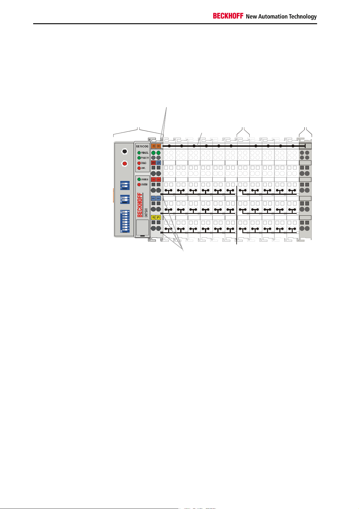
Bus coupler
BK7500
for the
Bus coupler
supply
bus terminal
K-Bus
0201
24V
0V
+ +
PE PE
Bus couplers for various
fieldbus systems
Power
contacts
Potential
isolation
You can use a variety of bus couplers to attach the electronic terminal row
quickly and easily to the various fieldbus systems, and you can also
subsequently convert to a different fieldbus system. The bus coupler deals
with all the necessary monitoring and control tasks for operating the
attached bus terminals, indeed all the operation and configuration of the
bus terminals is carried out via the bus coupler. The fieldbus, K bus and I/O
level are electrically isolated.
If the exchange of data across the fieldbus is temporarily interrupted, logic
states are preserved, digital outputs are cleared and analog outputs revert
to a reset value which can be individually configured for each output when
the equipment is set up.
The default for the analog outputs is 0V or 0mA. Digital outputs assume an
inactive state. The bus couplers' timeouts correspond to the usual times for
the field bus system. When changing over to a different bus system, pay
attention to the change in timeouts in the event of larger-scale bus system
cycle times.
6 BK7500
Page 7
The Beckhoff-SERCOS coupler BK7500
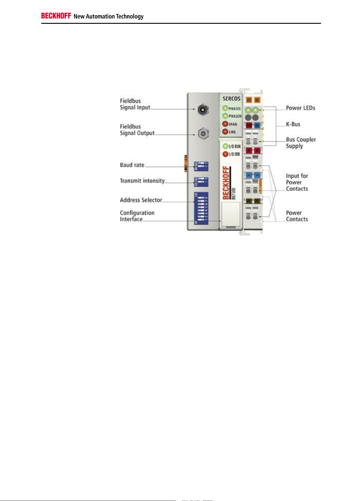
The interfaces
There are six ways of making a connection to a bus coupler. These
interfaces are designed as plug connections and spring terminals.
Basic information
24 V DC on the topmost
terminals
Lower 3 terminal pairs for
power input
maximum 24 V
maximum 10 A
Spring contacts at the side
Power supply
The bus couplers need an operating power of 24 V DC which is connected
via the topmost spring terminals, labeled "24 V” and "0 V”. This power
supply serves not only the electronic components of the bus coupler but
(via the K bus) also the bus terminals. The power supply of the bus coupler
circuitry and that of the K-bus (Terminal bus) are electrically isolated from
the voltage of the field level.
Power supply to the power contacts
The six lower connections with spring terminals can be used to supply
power to the peripherals. The spring terminals are connected in pairs to the
power contacts. The power supply to the power contacts has no
connection to the power supply of the bus couplers. The power input is
designed to permit voltages up to 24 V. The pair-wise arrangement and the
electrical connection between the feed terminal contacts makes it possible
to loop through the wires connecting to different terminal points. The load
on the power contact may not continuously exceed 10 A. The current
capacity between two spring terminals is the same as the capacity of the
connecting wires.
Power contacts
On the right-hand side face of the bus coupler are three spring contacts
which are the power connections. The spring contacts are recessed in slots
to prevent them from being touched. When a bus terminal is connected,
the blade contacts on the left-hand side of the bus terminal are connected
to the spring contacts. The slot and key guides at the top and bottom of the
bus couplers and bus terminals ensure reliable location of the power
contacts.
BK7500 7
Page 8

Basic information
Periphery level
Bus terminals
Bus coupler
24 V DC
SERCOS Fibre optic
Plug SERCOS Z1003
Serial interface under the
front flap
6 contacts at the side
3 supply groups:
fieldbus
K-bus
peripheral level
Setting up the power levels
in the bus terminal system
Fieldbus connection
There is a recessed front face on the left hand side. The typical SERCOS
connecting plugs can be inserted here. SERCOS consists of a fiber-optic
conductor ring into which the bus coupler is inserted. You need a fiberoptic conductor connector type SERCOS Z1003 for connection.
Configuration interface
On the lower part of the front face you will find the standard bus couplers
which are fitted with an RS232 interface. The miniature plug can be
attached to a PC by means of a connection cable and the configuration
software KS2000. This interface enables you to configure the bus terminals
, e.g. setting the amplification factor of the analog channels. The mapping
of the bus terminal data to the process view in the bus coupler can be
changed via the interface. You can also access the functionality of the
configuration interface via the fieldbus by means of the ADS
communications.
K-bus contacts
The connections between the bus coupler and the bus terminals are
effected by gold contacts at the right-hand side of the bus coupler. When
the bus terminals are plugged together, these gold contacts automatically
complete the connection to the bus terminals. The K bus is responsible for
the power supply to the electronic components of the K bus in the bus
terminals, and for the exchange of data between the bus coupler and the
bus terminals. Part of the data exchange takes place via a ring structure
within the K bus. Disengaging the K bus, for example by pulling on one the
bus terminals, will break this circuit so that data can no longer be
exchanged. However, there are mechanisms in place which enable the bus
coupler to locate the interruption and report it.
Supply isolation
The bus couplers operate with three independent supplies. The input
power supplies the electrically isolated K-bus circuitry in the bus coupler
and the K-bus itself. The power supply is also used to generate the
operating power for the fieldbus.
Note: All the bus terminals are electrically isolated from the K bus, so that
the K-bus is completely electrically isolated.
Terminal bus
8 BK7500
Field bus
Page 9
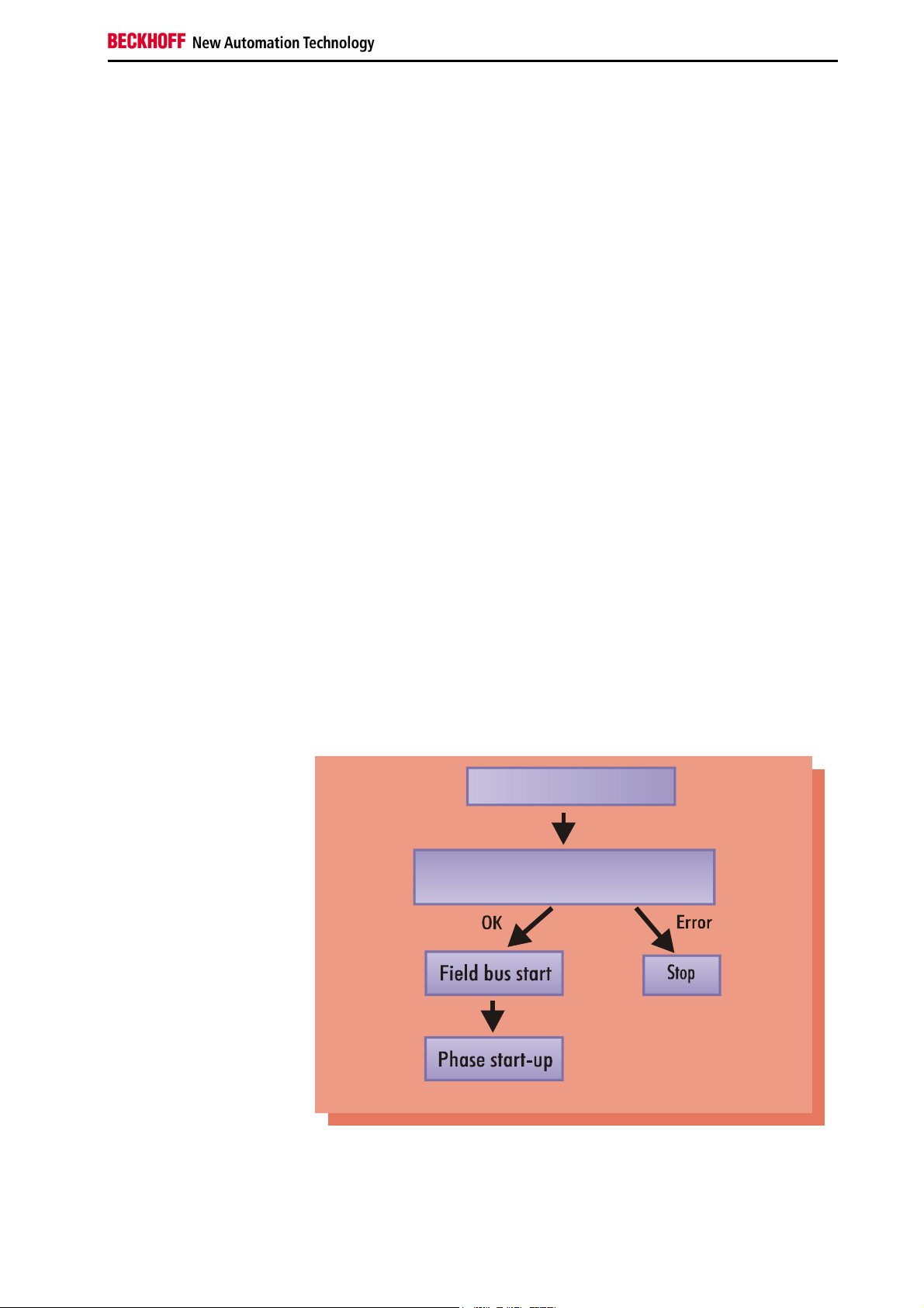
Power on selftest
Initialisation of the coupler
Start-up behavior of the bus
coupler
The operating modes of the bus coupler
When it is first switched on the bus coupler carries out a self-test to check
the functions of its components and the communications of the K bus, and
while this is going on the red I/O LED will flash. When the self-test has
been completed successfully, the bus coupler will begin to test the
attached bus terminals (the "bus terminal test”) and read in the
configuration from which it constructs an internal structure list, which is not
accessible from outside. If an error occurs the bus coupler will enter the
operating mode "STOP”. If the start-up sequence is completed without
errors the bus coupler will enter the mode "fieldbus start”.
The BK7500 is now in phase 0 (P0). In this phase it sends telegrams that it
has received to the next device in the ring (repeater function). In phase 0,
the master sends master sync. telegrams (MST). If these are received ten
times without interruption, the master switches to communication phase 1
(P1). Master data telegrams are now also sent. Each slave has its own
station address. The slave answers with a drive telegram (AT), and in this
way indicates its readiness for changing the phase to communication
phase 2 (P2). After the master has switched to phase 2, the SERCOS
interface is now in the stage of non-cyclic data exchange. Each cycle now
only involves communication with a device in the SERCOS ring. The time
slots required for cyclic data exchange are calculated, and are checked by
the connected devices. When all the slave devices have reported that they
are ready to switch-over, the master can switch to phase 3 with the MST.
In phase three (P3), the communication is already almost like that of phase
4. The only difference is that valid cyclic data is still not being transferred.
The time slots defined in phase 2 are valid, and are monitored. If the
communication is proceeding without error, phase 4 is entered.
Basic information
Cyclic data exchange
BK7500 9
Bus terminal test Structure list
Master Sync. Telegram (MST)
At the beginning of each cycle an MST is sent by the master to all the
slaves. The broadcast address is used for this. Each connected slave uses
this telegram to determine its send window.
Page 10
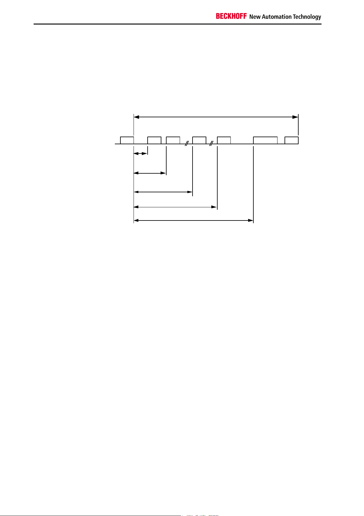
Basic information
Master Data Telegram (MDT)
The MDT is sent by the master as a broadcast to all devices. It contains
the data for all the slave devices. Because of different configurations, the
data length can vary.
Drive Telegram (AT)
Each slave sends its output data in the appropriate time slot. The telegram
contains its station address, so that the master can identify it.
t
Scyc
(CP4)
MST
t
1.1
AT AT
1
t
1.2
2
t
1.n
AT
t
1.n+1
AT
n
n+
t
2
MDT
MST
(CP4)
10 BK7500
Page 11

1
0
0
49
12
+
+
PE
PE
24V
E0
.0
00
.1
PE
PE
Mechanical construction and mounting
The Beckhoff bus terminal system is remarkable for its compact
construction and high degree of modularity. When you design the
installation you will need to plan for one bus coupler and some number of
bus terminals. The dimensions of the bus couplers do not depend on the
fieldbus system. The clear dimensions of the bus coupler are not exceeded
thanks to the use of fiber-optic cable with the Z1003 connectors.
Dimensions of a bus
coupler
94
Basic information
0201
00X0
0V
+ +
Assembly and connections
Maximum number of
terminals
The overall width of the construction is the width of the bus coupler,
including the bus end terminal, plus the width of the installed bus terminals.
The bus terminals are 12 mm or 24 mm wide, depending on their function.
The LC3100 has a width of 21 mm and the terminals then follow, as on the
coupler. Depending on the gauge of cables used the overall height of 68
mm may be overstepped by about 5 mm to 10 mm by the cables at the
front.
It takes only a slight pressure to latch the bus coupler and the various bus
terminals onto a supporting 35mm C rail and a locking mechanism then
prevents the individual housings from being removed. You can remove
them without effort if you first release the latching mechanism by pulling the
orange tab. You should carry out work on the bus terminals and the bus
coupler only while they are switched off: if you plug or unplug components
while the power is on you may briefly provoke some undefined state (and,
for instance, reset the bus coupler).
You can attach up to 64 bus terminals in series on the right-hand side of
the bus coupler. When you assemble the components, make sure that you
mount the housings so that each slot comes together with the
corresponding key. You cannot make any functional connections merely by
pushing the housings together along the supporting track. When they are
correctly mounted there should be no appreciable gap between the
adjacent housings.
The right-hand side of a bus coupler is mechanically similar to a bus
terminal. There are eight connections on the top which can be used to
connect to thick-wire or thin-wire lines. The connection terminals are spring
loaded. You open a spring terminal by applying a slight pressure with a
screwdriver or other pointed tool in the opening above the terminal and you
BK7500 11
Page 12

Basic information
Insulation test
PE power contacts
can then insert the wire into the terminal without any obstruction. When you
release the pressure the terminal will automatically close and hold the wire
securely and permanently.
The connection between bus couplers and bus terminals is automatically
effected by latching the components together. The K bus is responsible for
passing data and power to the electronic components of the bus terminals.
The field logic receives power via the power contacts. Latching the
components together has the effect that the series of power contacts
constitutes a continuous power track. Please refer to the circuit diagrams of
the bus terminals: some bus terminals do not loop these power contacts
through, or not completely (e.g. analog bus terminals or 4-channel digital
bus terminals). Each power input terminal interrupts the series of power
contacts and constitutes the beginning of a new track. The bus coupler can
also be used to supply power to the power contacts.
The power contact labeled "PE” can be used as protective earth or ground.
This contact stands proud for safety reasons and can carry short-circuit
currents of up to 125A. Note that in the interests of electromagnetic
compatibility the PE contacts are capacitively connected to the supporting
track. This may lead to spurious results and even damage to the terminal
when you test the insulation (e.g. insulation test for breakdown using a
230V mains supply to the PE line). You should therefore disconnect the PE
line on the bus coupler while you carry out insulation tests. You can
disconnect other power supply points for the duration of the test by drawing
the power supply terminals out from the remaining row of terminals by at
least 10mm. If you do this, there will be no need to disconnect the PE
connections.
The protective earth power contact ("PE”) may not be used for any other
connections.
12 BK7500
Page 13

Electrical data
The SERCOS coupler BK7500 and BK7510 differ by virtue of their capacity
levels. The following data distinguishes between a standard and an
economy variant (BK7500 and BK7510). Compatability with the other
SERCOS components is guaranteed in any case. Contrary to the standard
bus coupler, the economy variant is limited of the number of I/O´s. Thus,
there is no possibility of connecting inputs and outputs other than digital
ones. The following table lists an overview of all data:
Technical data Beckhoff SERCOSCoupler BK7500
Supply voltage
Input current
K bus supply current up to
Potential isolation
Number of bus terminals
Digital peripheral signals
24 V, - 15% +20%
105 mA typ.
900 mA max.
1.75 A max.
500 Vrms (K-bus / peripheral voltage)
64
256 inputs and outputs
Basic information
Analog peripheral signals
Peripheral bytes
Configuration
Fieldbus medium
Plug connection
Baud rate
Voltage of the power contact
Power contacts current
drawn
Electric strength
Typical weight
Operating temperature
Storage temperature
Relative humidity
Vibration/shock stability
EMC-immunity. Burst / ESD
Installation location
Protection class
Current consumption on the
K-Bus
128 inputs and outputs
512 input byte and 512 output byte
Via SERCOS Master or KS2000
Fibre optic Z1100
F-SMA-Norm IEC 872-2 Z1003 for Z1100
2 or 4 Mbaud ( 8 and 16 Mbaud in preparation)
24V DC / AC
10 A
500 Vrms (power contact / supply voltage)
150g
0°C ... +55°C
-25°C ... +85°C
95% without dew formation
According to IEC 68-2-6 / IEC 68-2-27
According to EN 61000-4-4 / EN 61000-4-2 limit value according to EN 50082-2-4
Arbitrary
IP20
For operation of the K-bus electronics, the bus terminals require energy
from the K-bus that is supplied by the bus coupler. Refer to the catalog or
the corresponding data sheets of the bus terminals for details of the K-bus
current consumption. In doing so, pay attention to the maximum output
current of the bus coupler that is available for powering the bus terminals.
Using a special power supply terminal (KL9400), power can be fed back
into the K-bus at any chosen point. If you wish to use a power supply
terminal, please contact Beckhoff’s technical support. .
BK7500 13
Page 14

Basic information
The peripheral data in the process image
When the bus coupler is first switched on it determines the configuration of
the attached input/output terminals and automatically assigns the physical
slots of the input/output channels to the addresses in the process image.
The bus coupler sets up an internal list of assignments in which each of the
input and output channels has a specific position in the process image. A
distinction is made here between input and output and between bit-oriented
(digital) and byte-oriented (analog, or complex) signal processing.
It also forms two groups, whereby one contains only inputs and the other
only outputs. In each group, the byte-oriented channels take the lowest
addresses, in ascending order, and these are then followed by the bitoriented channels.
Digital signals
(bit-oriented)
Digital signals are bit-oriented. This means that one bit of the process
image is assigned to each digital channel. The bus coupler sets up a block
of memory containing the current input bits and arranges to immediately
write out the bits from a second block of memory which belongs to the
output channels.
The precise assignment of the input and output channels to the process
image of the control unit is explained in detail in the Appendix by means of
an example.
Analog signals
(byte-oriented)
The processing of analog signals is always byte-oriented and analog input
and output values are stored in memory in a two-byte representation. The
values are held as "SIGNED INTEGER” or "twos-complement”. The digit
"0” represents the input/output value "0V”, "0mA” or "4mA”. When you use
the default settings, the maximum value of the input/output value is given
by "7FFF” hex. Negative input/output values, such as -10V, are
represented as "8000” hex and intermediate values are correspondingly
proportional to one another. The full range of 15-bit resolution is not
realized at every input/output level. If you have an actual resolution of 12
bits, the remaining three bits have no effect on output and are read as "0”
on input. Each channel also possesses a control and status byte in the
lowest value byte. If the control/status byte is mapped in the control unit
has to be configured in the master configuration software. An analog
channel is represented by 2 bytes user data in the process image.
Special signals and
interface
The BK7500 bus coupler supports bus terminals with additional interfaces,
such as RS232, RS485, incremental encoder, etc.. These signals can be
regarded in the same way as the analog signals described above. A 16-bit
data width may not be sufficient for all such special signals; the bus coupler
can support any data width. With regard to accessing these values, please
ensure that data consistency is safeguarded. That is to say, do not send
any "update" command between access operations and do not switch the
bus coupler to "freewheeling" mode.
Default assignment of
inputs and outputs to the
process image
When the bus coupler is first switched on it determines the number of
attached bus terminals and sets up a list of assignments. This list
distinguishes between analog channels and digital channels and between
input and output; which are grouped separately. The assignments begin
immediately to the left of the bus coupler. The software in the bus coupler
creates the assignment list by collecting the entries for the individual
channels one at a time, counting from left to right. These assignments
distinguish four groups:
14 BK7500
Page 15

Mapping by bit
Bk7500
Function type of the channel Assignment level
1.
2.
3.
4
Analog outputs byte-wise assignment
Digital outputs
Analog inputs
Digital inputs
Analog inputs/ouputs are representative of other complex multi-byte signal
bus terminals (RS232, SSI sensor interface, ...)
Overview of the subdivision of the process image in the bus coupler:
Output data in the bus
coupler
O0
...
byte-oriented data
...
Ox
Ox+1
bit-oriented data
Ox+y
Input data in the bus
coupler
I0
...
byte-oriented data
...
Ix
Ix+1
...
bit-oriented data
...
Ix+y
The path from the I/Os to
CPU
the PROFIBUS process
image
Basic information
bit-wise assignment
byte-wise assignment
bit-wise assignment
Mapping list
E
Mapping by
A
byte
Buildt inside the master by
software on the PC
E
Sercos
A
Sercos
E
A A
Mapping
list
and byte
Buildt automatically
by the bus coupler
E
BK7500 15
Page 16

Basic information
Data consistency
Processing complex signals
Data which contains no contradictions is said to be consistent. The
following consistency is required here:
1. The high byte and low byte of an analog value (word consistency),
2. The control/status byte and the corresponding parameter word for
accessing the register.
The interaction of the peripherals with the control unit means that data can
initially be guaranteed consistent only within an individual byte or word: the
bits which make up a byte or a word are read in together, or written out
together. Byte-wise consistency is quite adequate for processing digital
signals but is not sufficient for transferring values longer than eight bits,
such as analog values. The various bus systems guarantee consistency to
the required length. It is important to use the appropriate procedure for
importing this consistent data from the master bus system to the control
unit. You will find a detailed description of the correct procedure in the User
Guide of the appropriate bus system, in particular in the description of the
standard master units that are installed.
All byte-oriented signal channels such as RS232, RS485 and incremental
encoder, can use byte lengths greater than two. Apart from the actual
difference in length, the procedure is always comparable with that for
analog signals.
16 BK7500
Page 17

Starting operation and diagnostics
After switching on, the bus coupler immediately checks the connected
configuration. Error-free start-up is signalled by extinction of the red LED
“I/O ERR“. If the “I/O ERR” LED blinks, an error in the area of the terminals
is indicated. The error code can be determined from the frequency and
number of blinks. This permits rapid rectification of the error.
You will find a detailed description in the chapter entitled "The diagnostic
LEDs".
The diagnostic LEDs
The bus coupler has two groups of LEDs for the display of status. The
upper group with four LEDs indicates the status of the respective field bus.
The significance of the “field bus status“ LED is explained in the relevant
sections of this manual - it conforms to conventional field bus displays.
On the upper right hand side of the bus couplers are two more green LEDs
that indicate the supply voltage. The left hand LED indicates the 24 V
supply of the bus coupler. The right hand LED signals the supply to the
power contacts.
Local errors
Two LEDs, the “I/O” LEDs, in the area below the field bus status LEDs
referred to above, serve to indicate the operating status of the bus
terminals and the connections to these terminals. The green LED lights up
in order to indicate fault-free operation, where “error-free” implies that
communication with the fieldbus system is also operating correctly. The red
LED blinks with two different frequencies in order to indicate an error. The
error is encoded in the blinks as follows:
Code of flashes
Rapid flashing
First slow sequence
Second slow sequence
Location of error
The number of flashes corresponds to the position of the last bus terminal
before the error, not counting passive bus terminals such as power input
terminals.
The bus coupler will carry on flashing the error code even when you have
cleared the fault and its operating mode will remain at "Stop”. The only way
to restart the bus coupler is by switching the power supply off and on
again.
Basic information
Start of the error code
Type of error
Location of error
BK7500 17
Page 18

Basic information
Terminal bus error
Error code Error code
argument
Persistent,
continuous
blinking
1 pulse
2 pulses
3 pulses
4 pulses
5 pulses
6 pulses
7 pulses
EMC problems - Check power supply for overvoltage or
0
1
2
0
n (n > 0)
0 Terminal bus command error - No terminal connected; attach terminals.
0
n
n
0
1
2
Description Remedy
EEPROM checksum error
Inline code buffer overflow
Unknown data type
Programmed configuration
Incorrect table entry / bus
coupler
Incorrect table comparison
(terminal n)
Terminal bus data error
Break behind terminal n (0:
coupler)0
n
Terminal bus error with register
communication with terminal n
No ident of the MDT
No ident of the AT
Ident im MDT ans S370
konfigurated
Klemme wird vom Koppler nicht
unterstützt
Fieldbus error
Fieldbus error
The fieldbus status LEDs indicate the operational state of the fieldbus. The
functions of the SERCOS are indicated by the LED "PHASEL", PHASEH",
"LWL" and "DIAG".
The meaning of the first 4 LED`s:
PHASEL Communication phase low
PHASEH Communication phase high
DIAG without function
LWL shows quality of the fibre optic connection
undervoltage peaks
- Implement EMC measures
- If a K-bus error is present, it can be
localised by a restart of the coupler (by
switching it off and then on again)
- Set manufacturer’s setting with the
KS2000
- Connect fewer terminals; too many
entries in the table for the programmed
configuration
- Software update required for the coupler
- Check programmed configuration for
correctness
- Incorrect table entry / bus coupler
- One of the terminals is defective; halve
the number of terminals attached and
check whether the error is still present with
the remaining terminals. Repeat until the
defective terminal is located.
- Check whether the n+1 terminal is
correctly connected; replace if necessary.
– Check whether the end terminal 9010 is
connected.
Replace terminal n.
18 BK7500
Page 19

Diagnostic - LEDs of the
BK7500
I / O RUN PHASEL PHAESH Optical
fibres
lit
lit
lit
off
off
lit
off
lit
lit
off
lit
lit
off
off
off
off
off
off
off
off
Meaning
Telegrams are passing cyclically along the ring
Inputs are read and outputs are set.
The SERCOS ring is in phase 3
The SERCOS ring is in phase 2
The SERCOS ring is in phase 1
The SERCOS ring is in phase 0
Attention must be paid to the fact that there is a connection between the
green I/O LED and the field bus. The I/O LED lights up in connection with
access to the internal K-bus. The green I/O LED does not light up until a
trigger begins via the field bus. This means that the field bus must access
the bus coupler and the controller software must clear a cyclical trigger.
The green I/O LED indicates access to the internal K-bus and is reset after
100 ms.
The bus coupler queries the configuration of the bus terminals after
switching on and does not exchange data with the terminals. That is to say,
the red I/O LED goes off after an error-free startup without the green I/O
LED having to light up. The green I/O LED does not light up until data
exchange is begun via the Beckhoff-Lightbus.
Setting the Transmission Rate
Setting the transmission
2 Mbd
rate in the BK7500
Basic information
Remedy
4 Mbd
8 Mbd
16 Mbd
Setting the cable length to
the next device
Setting the Cable Length
The cable length is set at the coupler in the following stages: 0...15, 15...30
and 30...45 m. This is necessary in order to adapt the transmission power
to the cable attenuation.
0 .. 15 m
15 .. 30 m
30 ..45 m
BK7500 19
Page 20

Basic information
DIP switchh
Example
DIP-Bit 1-8
Setting the Station Address
In the BK7500 the station address must be set at the coupler's DIP switch.
20 + 01 + 02 + 23 + 04 + 05 + 26 + 27 = 201
1 + 0 + 0 + 8 + 0 + 0 + 64 + 128 = 201
20 BK7500
Page 21

SERCOS interface Coupler BK7500
SERCOS interface Coupler BK7500
System configurations and
device types
Introduction to the SERCOS Interface
System
The SERCOS interface (Serial Real-time Communication System) has
become established round the world in the numerical controller sector. The
BK7500 now also permits connection to the sensor / actuator level.
Its high real-time performance, and the interference immunity of the optical
fibre technology are important features of this bus system.
The BK7500 Lightbus is designed for fast data exchange at the sensor /
actuator level. Central control devices (such as, for example,
programmable logic controllers) communicate here over a fast serial
connection with distributed input and output devices. Data is exchanged
with these distributed devices cyclically. The central controller (master)
reads the input information from the slaves (drive telegram) and sends the
output information to the slaves (master data telegram).
A high data throughput is not in itself sufficient for successful use of a bus
system. Ease of handling, good diagnostic facilities and secure
transmission technology are also of the utmost importance if the user’s
demands are to be satisfied.
A single-master system can be implemented with the SERCOS interface. A
maximum of 254 slaves can be connected to one bus.
A BK7500 is a peripheral device (sensor/actuator) that reads input
information and passes output information on to the peripherals. It is also
possible to have device configurations that only handle either input or
output information. Typical Beckhoff Bus Terminals are binary
inputs/outputs for 24V or 230V, analog inputs, analog outputs, counters,
incremental encoders etc. The quantity of input and output information is
device-dependent, and is limited in the BK7500 to 32 bytes of input data
and 32 bytes of output data.
BK7500 21
Page 22

SERCOS interface Coupler BK7500
IDN
P-0-0001
Meaning
IDN
P-0-0010
Meaning
IDN
P-0-0011
Meaning
IDN
P-1-0012
Meaning
Name
I/O analog terminals
Type
Uint 16 Read/Write none
This parameter allows a table to be selected in the Bus Coupler. See also
the section on the register structure.
It can also be selected in the MDT.
Name
Current table
Type
Uint 16 read
This parameter allows a table to be selected in the Bus Coupler. See also
the section on the register structure.
It can also be selected in the MDT.
Name
Current register number Uint 16 read
Type
This parameter allows a table to be selected in the Bus Coupler. See also
the section on the register structure.
It can also be selected in the MDT.
Name
Register value
Type
Uint 16 read
Attributes Default
value
Attributes Default value
Attributes Default value
Attributes Default value Function
none
none
none
22 BK7500
Page 23

Function
The I/O Data Channel
Set and actual values are exchanged between the controller and the
BK7500 via the I/O data channels. Set and actual values may be
exchanged either cyclically or non-cyclically.
The controller needs the I/O data base in order to address the I/O data
channel.
The set and actual values of a BK7500 are divided into the following types.
I/O terminal types
Digital input terminals KL1xxx (without KL1501)
Digital output terminals KL2xxx (without KL2502)
Analog input terminal KL3xxx
Analog output terminal KL4xxx
Encoder terminal KL5xxx
Communication terminal KL6xxx
IDN
S-1-0000
Name
I/O data base
Type
IDN
Meaning
This operating data contains the IDN of the first I/O data channel, i.e. the
IDN of the channel container for this I/O data channel. The controller reads
this value in order to calculate the IDN of the I/O data channel.
IDN
S-1-0001
Name
Max I/O Channel
Type
Uint 16 Read/Write IDN: I/O base + 00001
Meaning
This operating data indicates the maximum number of I/O data channels in
the BK7500.
IDN
S-1-0002
Name
List I/O data channels Uint 16 Read/Write IDN: I/O base + 00002
Type
Meaning
The BK7500 writes the required I/O data channels with their absolute
addresses into this operating data.
IDN
S-2-0000
Name
I/O data channel
Type
Uint 16 Read
Meaning
This operating data contains the IDN of the first I/O data channel. Observe
the mapping of the terminals!
SERCOS interface Coupler BK7500
Attributes Default
value
Read/Write IDN: I/O base + 00000
Attributes Default
value
Attributes Default
value
Attributes Default
value
IDN: I/O data base + 0000
BK7500 23
Page 24

SERCOS interface Coupler BK7500
IDN
S-2-0001
Name
Channel type
Type
Attributes Default
Variable Read/Write I/O data channel + 0001
Meaning
The channel type describes the type of the terminal. This also depends on
the IDN P-0-0001 (see Table xxx).
KL1xxx (strict) 0x0001 16 bit data (without KL1501)
KL1xxx (compact) 0x0001 32 bit data (without KL1501)
KL2xxx (strict) 0x0001 16 bit data (without
KL2xxx (compact) 0x0001 32 bit data (without
KL1501 (strict/ compact) 0x8006 16 bit data
KL2502 (strict) 0x8003 16 bit data
KL3xxx (strict) 0x8002 16 bit data
KL3xxx (compact) 0x8002 32 bit data
KL4xxx (strict) 0x0003 16 bit data
KL4xxx / KL2502 (compact) 0x8003 16 bit data
KL5xxx (strict / compact) 0x8007 16 bit data
KL6xxx (standard) 0x8004 16 bit data
KL6xxx (alternative) 0x8004 16 bit data
IDN Name Type Attrib
utes
S-2-0002
Channel IDN list
IDN
I/O data channel + 0002
Meaning
This list contains the identification numbers supported by the relevant
channel.
IDN
S-2-0003
Name
Occupied inputs
Type
Uint 16 Read I/O data channel + 0003
Attrib
utes
Meaning
This operating data contains a bit mask specifying the occupied inputs for
this channel. Every bit that is set represents a usable input.
IDN
S-0-0011
Name Type Attrib
utes
I/O state class 1
Uint 16 Read
Meaning
Affects bits 11-13 in the I/O station's status word.
IDN Name Type Attrib
utes
S-0-0030
Manufacturer version
Variable, 1 byte Read 0xXXXX
Meaning
Shows the manufacturer version in the operating data.
value
Default
value
Default
value
Default
value
Default
value
Function
KL2502)
KL2502)
Function
Function
Function
Function
24 BK7500
Page 25

IDN Name Type Attrib
utes
S-0-0096
Slave identification
Uint 16 Read
Meaning
Shows the station's SERCOS address.
IDN Name Type Attrib
utes
S-0-0135
"Drive" status
Uint 16
Read 0xXXXX
Meaning
Shows the status of the BK7500 in the operating data via the service
channel.
IDN Name Type Attrib
utes
S-0-0143
System interface version string Read 0x
Meaning
Shows the version of the interface specification in the operating data.
IDN Name Type Attrib
utes
S-0-0185
Length of the data in the
AT
Read 0x
Meaning
Shows in the operating data the maximum length (in bytes) of the
configurable data in the drive telegram.
IDN
S-0-0186
Name Type Attrib
utes
Length of the data in the
MDT
Read 0x
Meaning
Shows in the operating data the maximum length (in bytes) of the
configurable data in the MDT.
IDN Name Type Attrib
utes
S-0-0187
IDN list of the data in the
AT
Read 0x
Meaning
Shows in the operating data a list of the cyclic IDNs to be processed as
actual values.
IDN Name Type Attrib
utes
S-0-0188
IDN list of the data in the
MDT
Read 0x
Meaning
Shows in the operating data a list of the cyclic IDNs to be processed as set
values.
Default
value
Default
value
Default
value
Default
value
Default
value
Default
value
Default
value
SERCOS interface Coupler BK7500
Function
Function
Function
Function
Function
Function
Function
BK7500 25
Page 26

SERCOS interface Coupler BK7500
IDN Name Type Attrib
utes
S-0-0290
Device type
Read 0x
Meaning
Bit 0,1
Shows the device type (drive, I/O, mixed station) in the operating data
0 0 = drive
1 0 = I/O station
0 1 = mixed station
1 1 = reserved
Bit 15
0 = device specified by the SERCOS working circle
1 = device specified by the manufacturer
IDN Name Type Attrib
utes
S-0-0291
I/O base
IDN Read 0x1000
Meaning
The base identification number of the I/O station is stored in the operating
data for calculation of the general I/O-specific identification numbers.
Default
value
Default
value
Function
Function
26 BK7500
Page 27

BK7500 Sercos Coupler
The transfer medium: plugs and cables
Fiber optic conductor: the SERCOS User group elaborated the
specification of a transmission technology based on fiber optic conductors
for applications in highly interference-prone environments and also to
increase the range.
Using the SERCOS bus couplers BK7500 the realization of optical Sercos
networks with ring technology (optical one fiber with plastic fiber conductor)
is possible. The maximum amount of stations is 254. The baud rate can be
adjusted via DIP switches on the BK7500. Additional information can be
find in the following table:
Fundamental properties of
optical fibre transmission
The Medium
Network topology
technology
Medium
Number of stations
with plastic optical
fibre
Min. bending radius
Transmission rate
Plug connector
It is possible to prepare plastic fiber-optic conductors using usual tools.
Special tools are needed to prepare the HCS conductors.
A closed ring must be established in one system. The data path begins in
the master and passes through all stations. The return path must end in the
master again.
The plastic fiber-optic cable can be processed without special tools. A
connector can be produced swiftly and reliably using a knife, pliers and
emery paper. The connector engages in the slaves.
Each station in the ring has on "incoming" and a "continuing" Interface.
Swapping of the "incoming" and "continuing" interfaces will not damage
them. In the activated state, the fault can be located easily. The red lit end
of the fiber-optic conductor is plugged into the interface that is not lit.
SERCOS interface Coupler BK7500
Ring system, active devices between the cable sections
Z1100 plastic optical fibre
Z1101 plastic optical fibre with PU cladding
254 stations in the ring
0.3 m to 45 m
3 cm
2, 4, 8 Mbit/s or 16 Mbit/s
Z1003 standard plug F-SMA for plastic optical fibres
BK7500 27
Page 28

Appendix
Example: composition of a process image
Appendix
in the Bus Coupler
Bk7500
KL1104
KL2114
KL3062
KL4002
KL9010
The hardware configuration:
Plug the terminals into the coupler in the sequence that can be seen in the
picture, and set address 2 at the "station address" DIP switch.
Connect the 24V /0V and the +/- contacts to the 24V DC supply voltage,
and switch the supply voltage on.
The 2 green LEDs at the supply assembly should now illuminate. If this is
not the case, the voltage must be checked.
Connect the BK7500 SERCOS Coupler to the SERCOS Master with the
optical fibre. The master's sender must be connected to the receiver at the
BK7500, and the sender at the coupler must be connected to the master's
receiver.
Examine the length of the cable between the BK7500 sender and the
SERCOS master receiver, and set the DIP switch for "cable length" (see
label on the Bus Coupler) correctly.
The same setting is required at the master end.
If the SERCOS Master is already active (detectable from the red light at the
SERCOS Master Sender) the "LWL" LED at the BK7500 should go out,
provided the connections are correct.
You must check the optical fibre if this LED continues to shine.
28 BK7500
Page 29

Configuration of the SERCOS master
Configuration of the AT
S-2-0000 Chn 1
S-2-0005 Chn 1
S-2-0010 Chn 2
S-2-0015 Chn 2
S-2-0040 Chn 1-16
Appendix
Data (Terminal KL3062)
Status (Terminal Kl3062)
Data (Terminal KL3062)
Status (Terminal Kl3062)
Data (All digital Input)
UINT 16
UINT 16
UINT 16
UINT 16
UINT 16
Configuration of the MDT
S-2-0020 Chn 1
S-2-0030 Chn 2
S-2-0050 Chn 1-16
Data (Terminal KL4002)
Status (Terminal l4002)
(All digital Outputs)
UINT 16
UINT 16
UINT 16
BK7500 29
Page 30

Appendix
(0x0000) := strict >> each clamp channel gets its own
Base settings
P-0-0001 Strict/Compact Mode (0/1)
I/O channel
S-0-0291 I/O Base UINT 16
(0x1000) := Pointer on the IDN S-1-0000
S-1-0000 Database UINT 16
(0x2000) := Pointer to the first I/O Channel >>> see S-
2-0000 Chn 1 Data (Terminal KL3062
UINT 16
30 BK7500
Page 31

Index
Index
Bit-oriented terminals 12
Byte-oriented terminals 12
Cables 25
Code of flashes 15
Data consistency 14
Diagnostic LEDs 15
DIP switch 18
End terminal 3
Example 26
If you have suggestions to make or ideas about our documentation, please send us an e-mail, stating the
version number, at
Dokumentation@Beckhoff.de.
Fiber optic conductor 25
Interfaces 5
K-bus 3, 11
Plugs 25
Power contacts 5
Power supply 5
Starting operation 15
BK7500 31
Page 32

Support and Service
Support and Service
Beckhoff and their partners around the world offer comprehensive support and service, making available
fast and competent assistance with all questions related to Beckhoff products and system solutions.
Beckhoff's branch offices and representatives
Please contact your Beckhoff branch office or representative for local support and service on Beckhoff
products!
The addresses of Beckhoff's branch offices and representatives round the world can be found on her
internet pages: http://www.beckhoff.com
You will also find further documentation for Beckhoff components there.
Beckhoff Headquarters
Beckhoff Automation GmbH
Eiserstr. 5
33415 Verl
Germany
phone: + 49 (0) 5246/963-0
fax: + 49 (0) 5246/963-198
e-mail: info@beckhoff.com
web: www.beckhoff.com
Beckhoff Support
Support offers you comprehensive technical assistance, helping you no only with the application of
individual Beckhoff products, but also with other, wide-ranging services:
• support
• design, programming and commissioning of complex automation systems
• and extensive training program for Beckhoff system components
hotline: + 49 (0) 5246/963-157
fax: + 49 (0) 5246/963-9157
e-mail: support@beckhoff.com
Beckhoff Service
The Beckhoff Service Center supports you in all matters of after-sales service:
• on-site service
• repair service
•
spare parts servive
• hotline service
hotline: + 49 (0) 5246/963-460
fax: + 49 (0) 5246/963-479
e-mail: service@beckhoff.com
32 BK7500
 Loading...