

Page 1

MODBUS BK7300
Version: 1.2
Date: 2012-09-28
Page 2

Page 3

Table of Contents
Table of Contents
1. Foreword 1
Notes on the documentation 1
Disclaimer 1
Trademarks 1
Patent Pending 1
Copyright 1
Delivery conditions 1
Safety Instructions 2
State at Delivery 2
Description of safety symbols 2
2. Basic information 3
The Beckhoff bus terminal system 3
The interfaces 5
Power supply 5
Power supply to the power contacts 5
Power contacts 5
Fieldbus connection 5
Configuration Interface 6
KS2000 Software 6
K-bus contacts 6
Supply isolation 6
The operating modes of the bus coupler 7
Mechanical construction 8
Electrical data 10
The peripheral data in the process image 10
Preparing for Operation and Diagnostics 12
Fieldbus errors 14
BK7300
Page 4

Table of Contents
3. MODBUS 15
Basic Principles 15
Bus Topology 15
Process Data and Memory Map 16
Settings and Parameterization 17
Parameterization Table 18
Protocol 19
ASCII 19
RTU 19
Functions 19
Read Digital Outputs (Function 1) 20
Read Digital Inputs (Function 2) 21
Read Analogue Outputs (Function 3) 22
Read Analogue Inputs (Function 4) 23
Writing a Digital Output (Function 5) 24
Writing an Analogue Output (Function 6) 25
Writing a Number of Digital Outputs (Function 15) 26
Writing a Number of Analogue Outputs (Function 16) 27
Writing and Reading a Number of Analogue Outputs or Inputs (Function 23) 28
Diagnostics 29
Echoes a query (Sub-Function 0) 29
Coupler Reset (Sub-Function 1) 30
Delete All Counter Contents (Sub-Function 10) 30
Bus Communication Error Counter (Sub-Function 11) 30
Error Answer Counter (Sub-Function 13) 30
Slave Answers (Sub-function 14) 30
Unsent Slave Answers (Sub-Function 15) 30
Number of Error Answers (Sub-Function 16) 30
BK7300 Error Answers 31
4. Appendix 32
MODBUS Interface 32
Terminal Mapping 34
List of References 34
5. Index 35
6. Support and Service 36
Beckhoff's branch offices and representatives 36
Beckhoff Headquarters 36
BK7300
Page 5

Foreword
Foreword
Notes on the documentation
This description is only intended for the use of trained specialists in control and automation technology
who are familiar with the applicable national standards. It is essential that the following notes and
explanations are followed when installing and commissioning these components.
The responsible staff must ensure that the application or use of the products describe d satisfy all the
requirements for safety, including all the relevant laws, regulations, guidelines and standards.
Disclaimer
The documentation has been prepared with care. The products described are, however, constantly under
development. For that reason the documentation is not in every case checked for consistency with
performance data, standards or other characteristics.
In the event that it contains technical or editorial errors, we retain the right to make alterations at any time
and without warning.
No claims for the modification of products that have already been supplied may be made on the basis of
the data, diagrams and descriptions in this documentation.
Trademarks
Beckhoff®, TwinCAT®, EtherCAT®, Safety over EtherCAT®, TwinSAFE® and XFC® are registered
trademarks of and licensed by Beckhoff Automation GmbH.
Other designations used in this publication may be trademarks whose use by third parties for their own
purposes could violate the rights of the owners.
Patent Pending
The EtherCAT Technology is covered, including but not limited to the following patent applications and
patents: EP1590927, EP1789857, DE102004044764, DE102007017835 with corresponding applications
or registrations in various other countries.
The TwinCAT Technology is covered, including but not limited to the following patent applications and
patents: EP0851348, US6167425 with corresponding applications or registrations in various other
countries.
Copyright
©
Beckhoff Automation GmbH.
The reproduction, distribution and utilization of this document as well as the communication of its contents
to others without express authorization are prohibited. Offenders will be held liable for the payment of
damages. All rights reserved in the event of the grant of a patent, utility model or design.
Delivery conditions
In addition, the general delivery conditions of the company Beckhoff Automation GmbH apply.
BK7300 1
Page 6
Foreword
Safety Instructions
State at Delivery
All the components are supplied in particular hardware and software configurations appropriate for the
application. Modifications to hardware or software configurations other than those described in the
documentation are not permitted, and nullify the liability of Beckhoff Automation GmbH.
Description of safety symbols
The following safety symbols are used in this operating manual. They are intended to alert the reader to
the associated safety instructions.
Serious risk of injury!
DANGER
WARNING
CAUTION
Warning
Note
Failure to follow the safety instructions associated with this symbol directly endangers
the life and health of persons.
Caution – Risk of injury!
Failure to follow the safety instructions associated with this symbol endangers the life
and health of persons.
Personal injuries!
Failure to follow the safety instructions associated with this symbol can lead to injuries
to persons.
Damage to the environment or devices
Failure to follow the instructions associated with this symbol can lead to damage to the
environment or equipment.
Tip or pointer
This symbol indicates information that contributes to better understanding.
2 BK7300
Page 7

Basic information
Basic information
Up to 64 bus terminals
each with 2 I/O channels
for any form of signal
Decentralized wiring of the
I/O level
IPC as control unit
Bus couplers for all current
bus systems
Standard C rail assembly
Modularity
Display of channel status
The K-bus
End terminal
The Beckhoff bus terminal system
The bus terminal system is the universal connecting link between a
fieldbus system and the sensor/actor level. A unit consists of a bus coupler,
which is the interface to the fieldbus, and up to 64 electronic terminals, of
which the last is an end terminal. Terminals, each with two I/O channels,
are available for any form of technical signal and can be combined as
desired. The various types of terminal are all constructed in the same way,
so that the planning costs are kept extremely low. The height and depth of
the construction are calculated for compact terminal cabinets.
Fieldbus technology makes it possible to use compact control
architectures. The I/O level does not need to be taken right up to the
control unit. Sensors and actors can be connected decentrally with minimal
lengths of cable. You can position the control unit at any convenient
location in the installation. Using an industrial PC as control unit makes it
possible to implement the operating and monitoring element as part of the
control hardware, so the control unit can be located on an operating desk,
control point or similar. The bus terminals constitute the decentralized
input/output level of the control unit in the switch cabinet and its
subordinate terminal cabinets. As well as the sensor/actor level, the power
unit of the equipment is also controlled via the bus system. The bus
terminal replaces a conventional terminal as the cabling level in the switch
cabinet; the switch cabinet can be made smaller.
The Beckhoff bus terminal system combines the advantages of a bus
system with the functionality of compact terminals. Bus terminals can be
used on all current bus systems and serve to reduce the diversity of parts
in the control unit, while behaving like the conventional standard units for
the relevant bus system and supporting the entire range of functionality of
the bus system.
The simple and compact assembly on a standard C rail, and the direct
cabling of actors and sensors without cross connections between the
terminals, serve to standardize the installation, as does the uniformly
designed labeling.
The small size and great flexibility of the bus terminal system mean that
you can use it anywhere that you could use a terminal and use any type of
connection – analog, digital, serial or direct sensors.
The modular construction of the terminal row, using bus terminals with
various functions, limits the number of unused channels to at most one per
function. Two channels to a terminal is the optimum solution for the number
of unused channels and the cost per channel. The possibility of using
power input terminals to provide separate power supplies also helps to
minimize the number of unused channels.
The integrated light-emitting diodes close to the sensor/actor indicate the
status of each channel.
The K-bus is the path taken by data within the terminal row. The bus
coupler carries the K bus through all the terminals by means of six contacts
on the side walls of the terminals, and the end terminal terminates the K
bus. The user does not need to know anything about the function of the K
bus or the internal operation of terminals and bus couplers. There are
numerous software tools available which provide for convenient planning,
configuration and operation.
BK7300 3
Page 8
Basic information
l
Power input terminals
for separately powered
groups
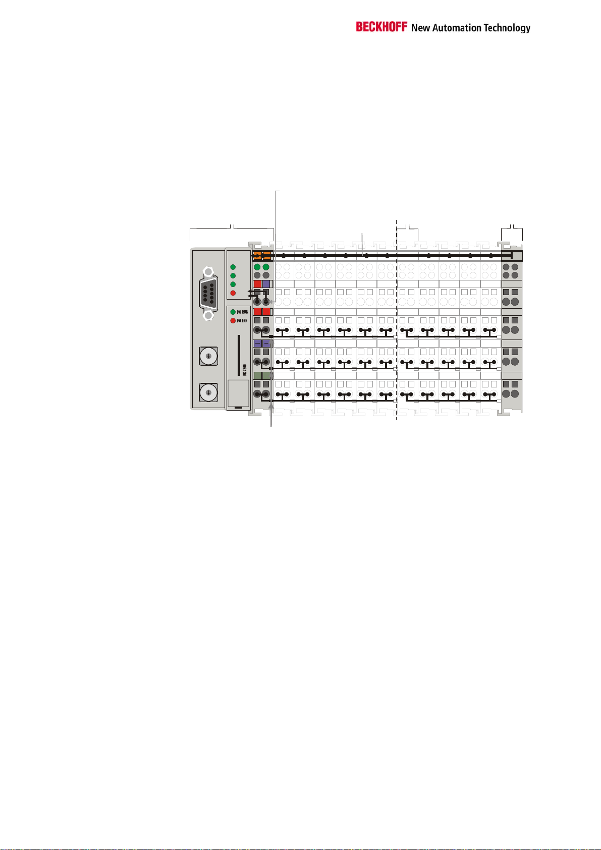
Three power contacts pass the operating power to the following terminals.
You can use power input terminals to subdivide the terminal row as desired
into groups, each with a separate power supply. These power input
terminals are not taken into account for addressing the terminals, you can
insert them at any position along the terminal row.
You can install up to 64 terminals on a terminal row, including power input
terminals and the end terminal.
The principle of the bus
terminal
Bus coupler
Bk7300
Power supp
for the
bus coupler
y
Potential
input
terminal
Bus end
terminal
K-Bus
Bus couplers for various
fieldbus systems
WD
RX
TX
ERROR
F
F
O
H
K
C
E
B
0201
24V
0V
++
PE
PE
Power
contacts
Potential
isolation
MODBUS
0
1
9
2
8
3
7
4
6
5
0
1
9
2
8
3
7
4
6
5
You can use a variety of bus couplers to attach the electronic terminal row
quickly and easily to the various fieldbus systems, and you can also
subsequently convert to a different fieldbus system. The bus coupler deals
with all the necessary monitoring and control tasks for operating the
attached bus terminals, indeed all the operation and configuration of the
bus terminals is carried out via the bus coupler. The fieldbus, K bus and I/O
level are electrically isolated.
If the exchange of data across the fieldbus is temporarily interrupted, logic
states are preserved, digital outputs are cleared and analog outputs revert
to a reset value which can be individually configured for each output when
the equipment is set up.
4 BK7300
Page 9
Basic information
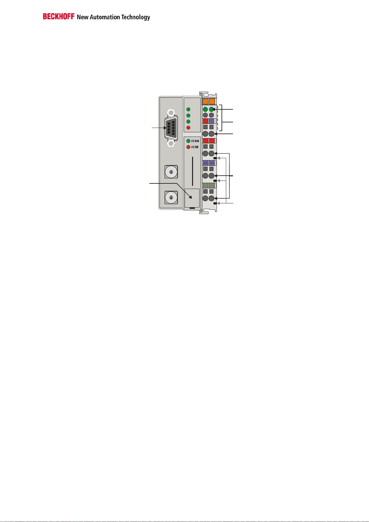
The interfaces
There are six ways of making a connection to a bus coupler. These
interfaces are designed as plug connections and spring terminals.
BK 7300
24V
++
PE PE
0201
Power LEDs
Bus coupler / power contacts
0V
K-Bus
Power supply bus coupler
24 V DC / GND
Input
power contacts
power contacts
The MODBUS - coupler
BK7300
MODBUS
Configuration
interface
MODBUS
WD
RX
TX
ERROR
0
1
9
2
8
3
7
4
6
5
BECKHOFF
0
1
9
2
8
3
7
4
6
5
24 V DC on the topmost
terminals
Power supply
The bus couplers need an operating power of 24 VDC which is connected
via the topmost spring terminals, labeled "24 V” and "0 V”. This power
supply serves not only the electronic components of the bus coupler but
(via the K bus) also the bus terminals. The power supply of the bus coupler
circuitry and that of the K-bus (Terminal bus) are electrically isolated from
the voltage of the field level.
Lower 3 terminal pairs for
power input
maximum 24 V
maximum 10 A
Power supply to the power contacts
The six lower connections with spring terminals can be used to supply
power to the peripherals. The spring terminals are connected in pairs to the
power contacts. The power supply to the power contacts has no
connection to the power supply of the bus couplers. The power input is
designed to permit voltages up to 24 V. The pair-wise arrangement and the
electrical connection between the feed terminal contacts makes it possible
to loop through the wires connecting to different terminal points. The load
on the power contact may not continuously exceed 10 A. The current
capacity between two spring terminals is the same as the capacity of the
connecting wires.
Spring contacts at the side
Power contacts
On the right-hand side face of the bus coupler are three spring contacts
which are the power connections. The spring contacts are recesse d in slots
to prevent them from being touched. When a bus terminal is connected,
the blade contacts on the left-hand side of the bus terminal are connected
to the spring contacts. The slot and key guides at the top and bottom of the
bus couplers and bus terminals ensure reliable location of the power
contacts.
Fieldbus connection
9 pin sub-D socket strip There is a recessed front face on the left hand side. The MODBUS
connection plug can be inserted here. A full description of the fieldbus
interfaces is found elsewhere in this manual. (In the section on The
Medium: Plugs and Cables)
BK7300 5
Page 10
Basic information
Serial interface under the
front cover
6 contacts at the side
3 supply groups:
fieldbus
K-bus
peripheral level
Setting up the power levels
in the bus terminal system
Configuration Interface
The standard bus couplers have an RS232 interface at the bottom of the
front face. The miniature connector can be joined to a PC with the aid of a
connecting cable and the KS2000 configuration software. The interface
allows the analogue channels to be configured. The functionality of the
configuration interface can also be reached via the fieldbus using the PLC
interface.
KS2000 Software
In order to link the MODBUS BK7300 coupler and the KS2000
configuration software, the coupler's address selection switch must be set
to "00", and it must be restarted (i.e. the coupler must be switched off and
then on again).
K-bus contacts
The connections between the bus coupler and the bus terminals are
effected by gold contacts at the right-hand side of the bus coupler. When
the bus terminals are plugged together, these gold contacts automatically
complete the connection to the bus terminals. The K bus is responsible for
the power supply to the electronic components of the K bus in the bus
terminals, and for the exchange of data between the bus coupler and the
bus terminals. Part of the data exchange takes place via a ring structure
within the K bus. Disengaging the K bus, for example by pulling on one the
bus terminals, will break this circuit so that data can no longer be
exchanged. However, there are mechanisms in place which enable the bus
coupler to locate the interruption and report it.
Supply isolation
The bus couplers operate with three independent supplies. The input
power supplies the electrically isolated K-bus circuitry in the bus coupler
and the K-bus itself. The power supply is also used to generate the
operating power for the fieldbus.
Note: All the bus terminals are electrically isolated from the K bus, so that
the K-bus is completely electrically isolated.
Bus terminalsBus coupler
Terminal bus
Field bus
Periphery level
24 V DC
6 BK7300
Page 11
Basic information
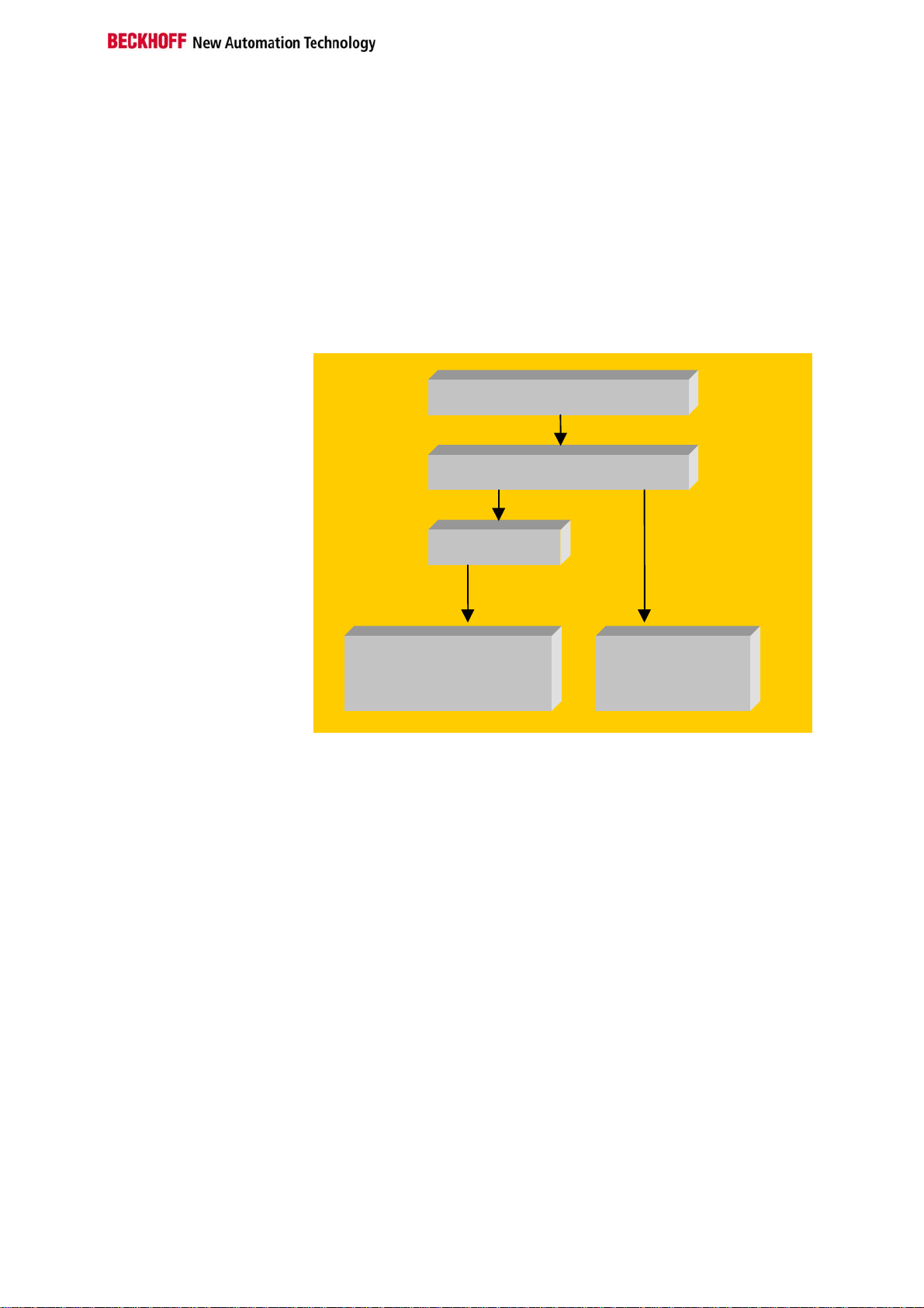
When it is first switched on the bus coupler carries out a self-test to check
Start-up behavior of the bus
coupler
The operating modes of the bus coupler
the functions of its components and the communications of the K bus, and
while this is going on the red I/O LED will flash. When the self-test has
been completed successfully, the bus coupler will begin to test the
attached bus terminals (the "bus terminal test”) and read in the
configuration from which it constructs an internal structure list, which is not
accessible from outside. If an error occurs the bus coupler will enter the
operating mode "STOP”. If the start-up sequence is completed without
errors the bus coupler will enter the mode "fieldbus start”.
Power on selftest
Bus terminal test
Structure list
OK
Field bus start
Error
Stop
BK7300 7
Page 12
Basic information
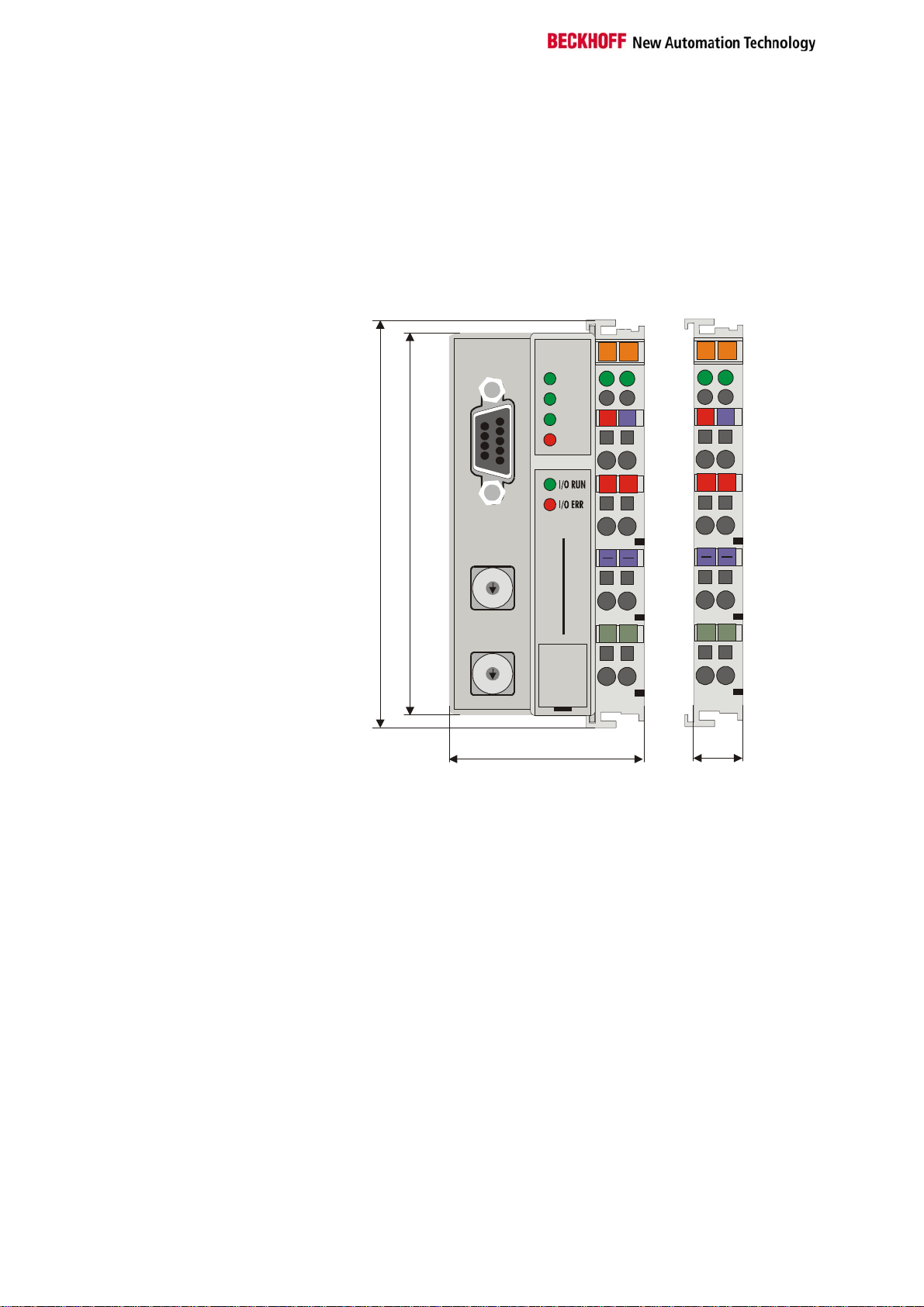
Mechanical construction
The Beckhoff bus terminal system is remarkable for its compact
construction and high degree of modularity. When you design the
installation you will need to plan for one bus coupler and some number of
bus terminals. The dimensions of the bus couplers do not depend on the
fieldbus system. If you use large plugs, for example like some of the bus
plugs used for the PROFIBUS, they may protrude above the overall height
of the cabinet.
Dimensions of a bus
coupler
MODBUS
RUN
RX
TX
Error
01
24V
02
0V
01
24V
02
0V
12
+
PE
100
94
+++
0
1
9
2
8
3
7
4
6
5
BECKHOFF
BK 7300
PEPEPE
0
1
9
2
8
3
7
4
6
5
47
The overall width of the construction is the width of the bus coupler,
including the bus end terminal, plus the width of the installed bus terminals.
The bus terminals are 12 mm or 24 mm wide, depending on their function.
Depending on the gauge of cables used the overall height of 68 mm may
be overstepped by about 5 mm to 10 mm by the cables at the front.
Assembly and connections It takes only a slight pressure to latch the bus coupler and the various bus
terminals onto a supporting 35 mm rail and a locking mechanism then
prevents the individual housings from being removed. You can remove
them without effort if you first release the latching mechanism by pulling the
orange tab. You should carry out work on the bus terminals and the bus
coupler only while they are switched off: if you plug or unplug components
while the power is on you may briefly provoke some undefined state (and,
for instance, reset the bus coupler).
Maximum number of
terminals
You can attach up to 64 bus terminals in series on the right-hand side of
the bus coupler. When you assemble the components, make sure that you
mount the housings so that each slot comes together with the
corresponding key. You cannot make any functional connections merely by
pushing the housings together along the supporting track. When they are
correctly mounted there should be no appreciable gap between the
adjacent housings.
8 BK7300
Page 13

Basic information
The right-hand side of a bus coupler is mechanically similar to a bus
terminal. There are eight connections on the top which can be used to
connect to thick-wire or thin-wire lines. The connection terminals are spring
loaded. You open a spring terminal by applying a slight pressure with a
screwdriver or other pointed tool in the opening above the terminal and you
can then insert the wire into the terminal without any obstruction. When you
release the pressure the terminal will automatically close and hold the wire
securely and permanently.
The connection between bus couplers and bus terminals is automatically
effected by latching the components together. The K bus is responsible for
passing data and power to the electronic components of the bus terminals.
In the case of digital bus terminals, the field logic receives power via the
power contacts. Latching the components together has the effect that the
series of power contacts constitutes a continuous power track. Please refer
to the circuit diagrams of the bus terminals: some bus terminals do not loop
these power contacts through or not completely (e.g. analog bus terminals
or 4-channel digital bus terminals). Each power input terminal interrupts the
series of power contacts and constitutes the beginning of a new track. The
bus coupler can also be used to supply power to the power contacts.
Insulation test
The power contact labeled "PE” can be used as protective earth or ground.
This contact stands proud for safety reasons and can carry short-circuit
currents of up to 125A. Note that in the interests of electromagnetic
compatibility the PE contacts are capacitively connected to the supporting
track. This may lead to spurious results and even damage to the terminal
when you test the insulation (e.g. insulation test for breakdown using a
230V mains supply to the PE line). You should therefore disconnect the PE
line on the bus coupler while you carry out insulation tests. You can
disconnect other power supply points for the duration of the test by drawing
the power supply terminals out from the remaining row of terminals by at
least 10mm. If you do this, there will be no need to disconnect the PE
connections.
PE power contacts The protective earth power contact ("PE”) may not be used for any other
connections.
BK7300 9
Page 14

Basic information
Electrical data
The MODBUS – the fieldbus-specific electrical data is listed in this section.
The following table gives an overview of all the data:
Technical data BK7300
Supply voltage
Input current
Power-on surge
K bus supply
current up to
Configuration
facility
Number of bus
terminals
Digital peripheral
signals
Analogue peripheral
signals
Baud rate
Protocol
Bus connection
Voltage of the
power contact
Power contacts
current drawn
Electric strength
Typical weight
Operating
temperature
Storage
temperature
Relative humidity
Vibration/shock
stability
EMC immunity/
transmission
Installation location
Protection class
24 V DC
70mA +
(total K-bus current)/4
500 mA max.
2.5 x steady operating current
1750 mA max.
via KS2000 or the controller
64
256 inputs/outputs
128 inputs/outputs
From 150 baud to 38400 baud
RTU and ASCII
D-Sub RS 485
9-pin
24 V DC / AC max.
10 A max.
500 V (power contact / supply voltage / fieldbus)
none
170 g
0°C ... +55°C
-20°C ... +85°C
95% without dew formation
according to IEC 68-2-6 / IEC 68-2-27
according to EN 50082 (ESD, burst) / EN 50081
Any
IP20
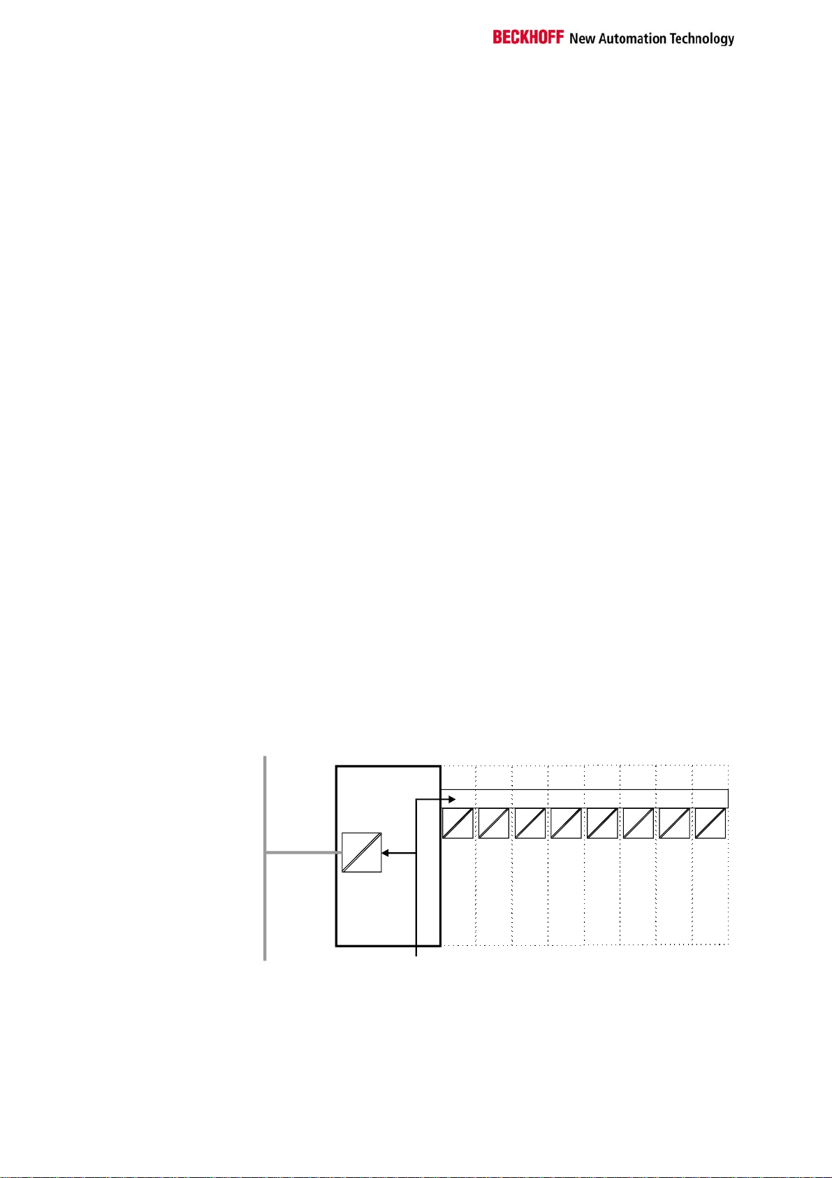
Current consumption on the
K-Bus
For operation of the K-bus electronics, the bus terminals require energy
from the K-bus that is supplied by the bus coupler. Refer to the catalogue
or the corresponding data sheets of the bus terminals for details of the Kbus current consumption. In doing so, pay attention to the maximum output
current of the bus coupler that is available for powering the bus terminals.
Using a special power supply terminal (KL9400), power can be fed back
into the K-bus at any chosen point. If you wish to use a power supply
terminal, please contact Beckhoff’s technical support.
The peripheral data in the process image
When the bus coupler is first switched on it determines the configuration of
the attached input/output terminals and automatically assigns the physical
slots of the input/output channels to the addresses in the process image.
The bus coupler sets up an internal list of assignments in which each of the
input and output channels has a specific position in the process image. A
10 BK7300
Page 15

Basic information
distinction is made here between input and output and between bit-oriented
(digital) and byte-oriented (analog, or complex) signal processing.
It also forms two groups, whereby one contains only inputs and the other
only outputs. In each group, the byte-oriented channels take the lowest
addresses, in ascending order, and these are then followed by the bitoriented channels.
Digital signals
(bit-oriented)
Digital signals are bit-oriented. This means that one bit of the process
image is assigned to each digital channel. The bus coupler sets up a block
of memory containing the current input bits and arranges to immediately
write out the bits from a second block of memory which belongs to the
output channels.
The precise assignment of the input and output channels to the process
image of the control unit is explained in detail in the Appendix by means of
an example.
Analog signals
(byte-oriented)
The processing of analog signals is always byte-oriented and analog input
and output values are stored in memory in a two-byte representation. The
values are held as "SIGNED INTEGER” or "twos-complement”. The digit
"0” represents the input/output value "0 V”, "0 mA” or "4 mA”. When you
use the default settings, the maximum value of the input/output value is
given by "7FFF” hex. Negative input/output values, such as -10 V, are
represented as "8000” hex and intermediate values are correspondingly
proportional to one another. The full range of 15-bit resolution is not
realized at every input/output level. If you have an actual resolution of
12 bits, the remaining three bits have no effect on output and are read as
"0” on input. Each channel also possesses a control and status byte in the
lowest value byte. If the control/status byte is mapped in the control unit
has to be configured in the master configuration software. An analog
channel is represented by 2 bytes user data in the process image.
Special signals and
interface
A bus coupler supports bus terminals with additional interfaces, such as
RS232, RS485, incremental encoder, etc.. These signals can be regarded
in the same way as the analog signals described above. A 16-bit data
width may not be sufficient for all such special signals; the bus coupler can
support any data width.
Default assignment of
inputs and outputs to the
process image
When the bus coupler is first switched on it determines the number of
attached bus terminals and sets up a list of assignments. This list
distinguishes between analog channels and digital channel s and between
input and output; which are grouped separately. The assignments begin
immediately to the left of the bus coupler. The software in the bus coupler
creates the assignment list by collecting the entries for the individual
channels one at a time, counting from left to right.
These assignments distinguish four groups:
Function type of the channel Assignment level
1.
2.
3.
4
Analog outputs byte-wise assignment
Digital outputs bit-wise assignment
Analog inputs byte-wise assignment
Digital inputs bit-wise assignment
Analog inputs/ouputs are representative of other complex multi-byte signal
bus terminals (RS232, SSI sensor interface, ...)
BK7300 11
Page 16

Basic information
Data consistency Items of data are said to be consistent if their content all belongs together,
and if they are transmitted as a single block. Examples of data items that
belong together are: 1. the high and low bytes of an analogue value (word
consistency), and 2. a control/status byte and the associated parameter
word for access to the registers. Data consistency in the interaction of
peripheral devices and their controllers is, in a basic sense, only assured
for a single byte. In other words, the bits of a byte are read in or written
together. Byte consistency is sufficient for handling digital signals.
Whenever values have a length of more than 8 bits, analogue values for
instance, the consistency must be extended. The different bus systems
guarantee consistency up to the required length. Correct transfer of the
consistent data from the bus system master to the controller is important.
The corresponding manual for the bus system will provide a detailed
description of the correct procedure, in particular the description of the
used master interfaces. Those chapters of this manual that deal with the
fieldbus refer to the most widespread interfaces.
Processing complex signals
All byte-oriented signal channels such as RS232, RS485 and incremental
encoder, can use byte lengths greater than two. Apart from the actual
difference in length, the procedure is always comparable with that for
analog signals
Preparing for Operation and Diagnostics
After switching on, the bus coupler immediately checks the connected
configuration. Error-free start-up is signaled by extinction of the red LED
“I/O ERR“. If the “I/O ERR” LED blinks, an error in the area of the terminals
is indicated. The error code can be determined from the frequency and
number of blinks. This permits rapid rectification of the error.
The diagnostic LEDs The bus coupler has two groups of LEDs for the display of status. The
upper group with four LEDs indicates the status of the respective field bus.
The significance of the “field bus status“ LED is explained in the relevant
sections of this manual - it conforms to conventional field bus displays.
On the upper right hand side of the bus couplers are two more green LEDs
that indicate the supply voltage. The left hand LED indicates the 24 V
supply of the bus coupler. The right hand LED signals the supply to the
power contacts.
Local errors Two LEDs, the “I/O” LEDs, in the area below the field bus status LEDs
referred to above, serve to indicate the operating status of the bus
terminals and the connections to these terminals. The green LED lights up
in order to indicate fault-free operation. The red LED blinks with two
different frequencies in order to indicate an error. The error is encoded in
the blinks as follows:
Blink code
Fast blinking
First slow sequence
Second slow sequence
Start of the error code
Error code
Error code argument
Start of the error code Error type Error location
12 BK7300
Page 17

Basic information
Error code Error
argument
Persistent,
continuous
blinking
1 pulse
2 pulses
3 pulses
4 pulses
5 pulses
14 pulses
15 pulses
16 pulses
EMC problems - Check power supply for overvoltage or
0
1
2
0
n (n > 0)
0 K-bus command error - No terminal connected; attach terminals.
0
n
n K-bus error with register
n Terminal n has the wrong format - Start the coupler again, and if the error
n Number of terminals is no longer
n Length of the terminal bus data is no
Description Remedy
undervoltage peaks
- Implement EMC measures
- If a terminal bus error is present, it can be
localized by a restart of the coupler (by
switching it off and then on again)
EEPROM checksum error
Inline code buffer overflow
Unknown data type
Programmed configuration
Incorrect table entry / bus coupler
Incorrect table comparison
(terminal n)
K-bus data error
Break behind terminal n (0: coupler)
communication with terminal n
correct
longer correct
- Set manufacturer’s setting with the KS2000
- Connect fewer terminals; too many entries in
the table for the programmed configuration
- Software update required for the coupler
- Check programmed configuration for
correctness
- Incorrect table entry / bus coupler
- One of the terminals is defective; halve the
number of terminals attached and check
whether the error is still present with the
remaining terminals. Repeat until the
defective terminal is located.
- Check whether the n+1 terminal is correctly
connected; replace if necessary.
– Check whether the end terminal 9010 is
connected.
Replace terminal
occurs again then exchange the terminal
- Start the coupler again, and if the error
occurs again after this, use the KS2000
software to set manufacturer’s settings
- Start the coupler again, and if the error
occurs again after this, use the KS2000
software to set manufacturer’s settings
The number of pulses (n) indicates the position of the last bus terminal
before the fault. Passive bus terminals, such as a power feed terminal, are
not included in the count.
In the case of some errors, rectification does not cause the bus coupler to
leave the blink sequence. The bus coupler stays in the "Stop" state. The
bus coupler can only be re-started either by switching the power supply off
and on again, or by a software reset.
Insertion and removal of bus terminals is only permitted when switched off.
The electronics in the bus terminals and in the bus coupler are prot ected to
a large measure against damage, but incorrect function and damage
cannot be ruled out if they are plugged in under power.
The occurrence of a fault in the course of operation does not immediately
trigger the display of error codes by the LEDs. The bus coupler must be
requested to diagnose the bus terminals. The diagnostic request is
generated after switching on.
MODBUS LEDs WD Watchdog is active
RX Receive Data
Data is being received
TX Transmit Data
Data is being transmitted
Error Error Data
Error in data transmission, checksum error
BK7300 13
Page 18

Basic information
XTX
MODBUS
WD
R
Error
If a K-bus error occurs during operation, the procedures for reaction to a K-
bus error are executed in accordance with the parameterization. If the Kbus error occurs during booting, the slave is not included in the data
exchange.
Fieldbus errors
WD A fieldbus error only occurs when the watchdog (WD) period has elapsed.
The watchdog is preset to 1000 ms. The WD is activated as soon as a
"write" access has been made to the coupler's process data (WD LED
goes on). After this, another "write" command must be sent to the process
data within the set WD time, in order to start the WD from zero again.
Once a WD error has occurred, data communication can only be restarted
by resetting the coupler (see "Coupler Reset", under Diagnostics).
The maximum watchdog time is 65000 ms, and it can be set by rotary
switch or via the KS2000 software.
14 BK7300
Page 19

MODBUS
MODBUS
Basic Principles
The MODBUS is a master-slave bus system in which only one device (the
master) actively starts a transaction (queries). The passive device (the
slave) then sends an answer (response) if the telegram was directly
addressed to it and provided that it has no errors.
Bus Topology
Physically, the BK7300 uses RS485 transmission. This means that a twowire cable is needed for the data transmission. The topology is linear. At
the beginning and end of the lines the bus requires termination resistors.
The structure of the Modbus network is similar to that of PROFIBUS.
0201
0201
++
PE PE
++
PE PE
01
+
PE
020201
MODBUS
RUN
RX
24V
0V
TX
++
+++
0
1
9
2
8
3
7
4
6
5
BECKHOFF
BK 7300
PE PE
PEPEPE
0
1
9
2
8
3
7
4
6
5
Broadcast function
The Beckhoff bus couplers support the broadcast function. For this
purpose the slave address in the telegram must be set to "00". Slaves do
not answer a broadcast. Not all functions are supported.
Functions that support a broadcast:
• 5 Force single coil
• 6 Preset single register
• 15 Force multiple coils
• 16 Preset multiple register
PIN assignment
The BK7300 uses RS485 for the data transmission. A screened two-wire
cable is sufficient. The connection to the coupler is a 9-pin sub-D socket.
The data line is connected to PIN 3 and PIN 8.
++
PE
02010201
0201
01
+
PE
PE
0201
020201
MODBUS
RUN
RX
24V
0V
TX
++
++
+++
0
1
9
2
8
3
7
4
6
5
BECKHOFF
BK 7300
PE
PE
PE
PE
PEPEPE
0
1
9
2
8
3
7
4
6
5
02010201
MODBUS
RUN
RX
TX
0
1
9
2
8
3
7
4
6
5
BECKHOFF
BK 7300
0
1
9
2
8
3
7
4
6
5
0201
020201
24V
0V
++
++
+++
PE PE
PE PE
PEPEPE
++
PE PE
02010201
0201
01
+
PE
BK7300 15
Page 20

MODBUS
D
Cable
Sub-D socket
Bus termination
BK7300
TxD/RxD (3)
RxD/TxD (8)
shield
PE
BK7300
RxD/TxD (3)
TxD/RxD (8)
5: GND
8: RxD/TxD
6: 5 V
The MODBUS requires termination resistors at the beginning and end of
the bus lines.
5 V (6)
3: RxD/Tx
1
RxD/TxD (3)
TxD/RxD (8)
GND (5)
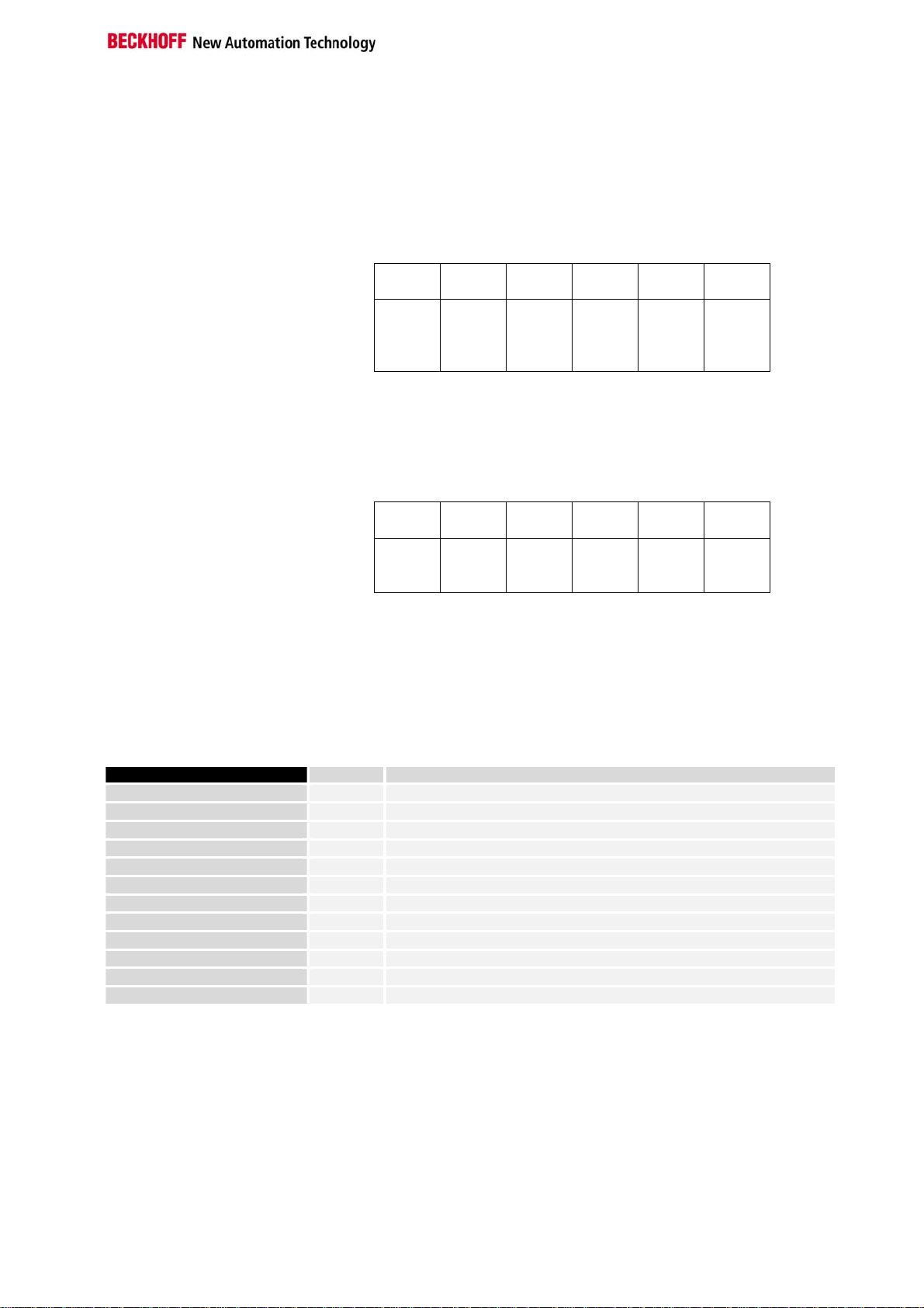
The following example illustrates how the process image is constructed in
Process Data and Memory Map
the coupler, and the functions of the MODBUS telegram with which digital
and analogue values can be read.
The input process image in the BK7300 starts from address 0x0000. All the
byte-oriented bus terminals (see Appendix) are entered here into the
process image first. The bit-oriented bus terminals them follow, and each
word is filled before starting a new one.
The output process image starts at address 0x0800. The byte-oriented bus
terminals are again here entered first, and the bit-oriented terminals follow.
All the digital signals can be directly addressed with functions 1, 2, 5 and
15.
16 BK7300
Page 21

MODBUS
RUN
RX
TX
Error
02
24V
0V
++
++
BECKHOFF
BK 7300
PEPEPE
+PE+PE++
PE PE
PE PE
++
PE PE PE PE
PE
MODBUS
0
1
9
2
8
3
7
4
6
5
0
1
9
2
8
3
7
4
6
5
Input Function 4,23
0x0000
0x0001
0x0002
Output Function 3,6,16,23
0x0800
0x0801
0x0802
WORD 1
WORD 2
WORD 1
WORD 2
Input Function 2
0x0001
0x0002
0x0003
0x0004
Output Function 1,5,15
0x0001
0x0002
0x0003
0x0004
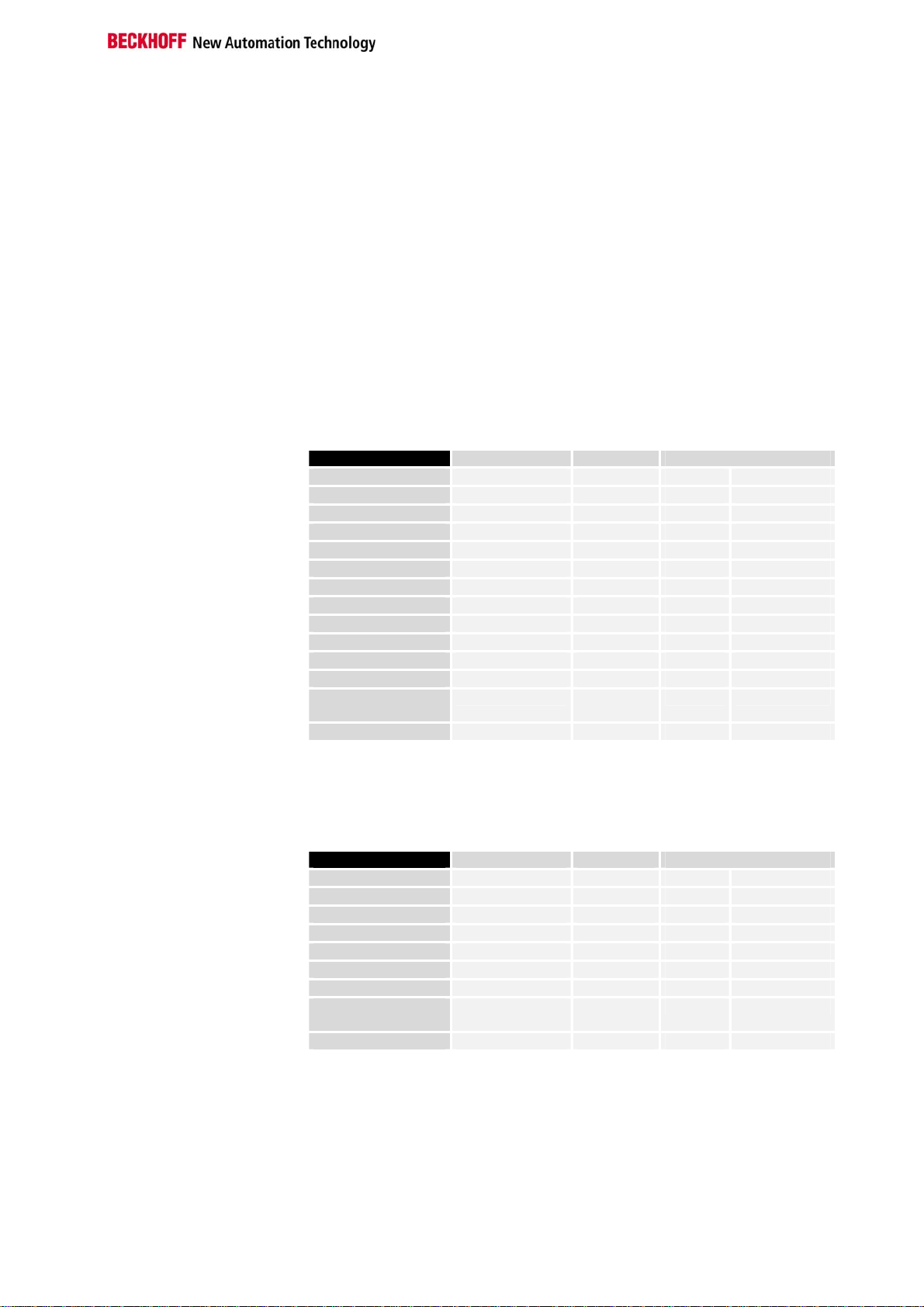
Settings and Parameterization
The Modbus is parameterized by means of the rotary switch on the
BK7300. Only the bus coupler's end terminal may be inserted for this.
Only plug the KL9010 into the BK7300. Use the rotary switch to select the
parameters. The x10 address switch is used to select the parameter, while
the x1 address switch is used for the associated setting. The settings can
be found in the table. Connect the bus coupler's 24 V supply, and the
Modbus coupler will now start up in parameterization mode. The LEDs WD,
RX, TX and ERROR are now toggled, and the LEDs I/O RUN and I/O ERR
give the function value.
BK7300 17
Page 22

MODBUS
Example
You want to check whether the correct baud rate has been set.
1. Switch off the coupler's 24 V supply
2. Remove all the terminals except the KL9010 end terminal
3. Set the x10 address selection switch to 0 and the x1 switch to 3
4. Switch on the coupler's 24 V supply again
The coupler indicates the set baud rate via the LEDs.
3 x flashes of the I/O RUN and I/O ERR LEDs means 9600 baud
WD,RX,TX,ERROR LEDs
1 2 3 1 2 3 1 2 3 1 2 3
I/O Run, I/O ERR
Now you want to set a new rate of 1200 baud
5. Switch off the coupler's 24 V supply
6. Set the x10 address selection switch to 3 and the x1 switch to 6
7. Switch on the coupler's 24 V supply again
The coupler indicates the new set baud rate via the LEDs.
6 x flashes of the I/O RUN and I/O ERR LEDs means 1200 baud
Incorrect Entry If a parameter is set that the Modbus coupler does not recognize, this is
indicated by a constant even flashing of the I/O RUN and I/O ERR LEDs,
while all the other LEDs remain off.
KS2000 The parameterization settings can also be carried out with the KS2000
software.
sEnd of Frame Time
Watchdog 100 ms
Watchdog 1000 ms
Factory setting
Parameterization Table
Parameter x 10 x 1 Default Parameter value
0 1..9 - Indicates the parameter of the x 10 function
Modbus
Frame
Baud rate
1
2
3
4 0..9 0 In ms for RTU mode (0 dependent on the baud
5 0..9 0 Watchdog x 100 ms
6 0..9 1 Watchdog x 1000 ms
9 9
1 RTU mode
2
1 8 data bits, no parity one stop bit
2 8 data bits even Parity one stop bit
3 8 data bits odd Parity one stop bit
4 7 data bits even Parity one stop bit
5 7 data bits odd Parity one stop bit
6 one stop bit
7 2 stop bits
8 8 data bits, no parity two stop bits
9 8 data bits even Parity two stop bits
10 8 data bits odd Parity two stop bits
11 7 data bits even Parity two stop bits
12
1 38400 baud
2 19200 baud
3 9600 baud
4 4800 baud
5 2400 baud
6 1200 baud
7 600 baud
8 300 baud
9
1
ASCII mode
1
7 data bits odd Parity two stop bits
3
150 baud
rate)
In seconds for ASCII mode (0 EOF time switched
off)
18 BK7300
Page 23
MODBUS
Protocol
ASCII
In ASCII mode the telegram starts with a colon ( : ) character (0x3A), and
ends with a carriage return and a line feed (CRLF) (0x0D, 0x0A). The
characters transferred are represented in the ASCII code.
ASCII frame
start address function data LRC END
1
charact
er
2
charact
ers
:
2
charact
ers
n
charact
ers
2
charact
ers
2
charact
ers
CRLF
RTU
In RTU mode the protocol starts with a pause of 3.5 character times, and
finishes in the same way (illustrated in the diagram with T1-T2-T3-T4). The
characters permitted for transmission in all fields are hexadecimal 0... 9,
A..., F.
RTU frame
start address function data CRC
END
Check
T1-T2-
T3-T4 1 charact
er
1
charact
er
n
charact
ers
2
charact
ers
T1-T2-
T3-T4
Functions
In the MODBUS protocol, the functions determine whether data are to be
read or written, and what kind of data is involved. In the ASCII protocol the
fourth and fifth bytes are function bytes, while in the RTU protocol it is the
second byte.
The Beckhoff MODBUS coupler supports the following functions:
Function Code Description
Read coil status
Read input status
Read holding registers
Read input registers
Force single coil
Preset single register
Diagnostics
Force multiple coils
Preset multiple registers
Read / Write Registers
1 Read digital outputs
2 Read digital inputs
3 Read analogue outputs / GPR
4 Read analogue inputs / GPR
5 Write one digital output
6 Write one analogue output / GPR
8 Read the MODBUS diagnostic register
15 Write a number of digital outputs
16 Write a number of analogue outputs / GPR
23 Write and read a number of process data outputs / GPRs
GPR – General Preset Register (see Modbus Interface)
The functions are briefly described below and clarified with the aid of an
example.
BK7300 19
Page 24

MODBUS
Read Digital Outputs (Function 1)
READ COIL STATUS Function 1 can be used to read the settings of the digital outputs.
In this example the first 10 digital outputs of slave number 11 are read. The
start address is zero. If an offset is to be entered, this is done in the "Start
address" field.
Query
Start address high
Byte Name Example RTU ASCII
Start frame
Slave address
Function code
Start address low
Count high
Count low
Error Check
LRC / CRC
End of frame
„:“
11 0x0B „0B“ 0x30, 0x42
1 0x01 „01“ 0x30, 0x31
0 0x00 „00“ 0x30, 0x30
0 0x00 „00“ 0x30, 0x30
0 0x00 „00“ 0x30, 0x30
10 0x0A „10“ 0x31, 0x30
0xBC
0xA7
t1-t2-t3 CRLF 0xD, 0xA
0x3A
„E4“ 0x45, 0x34
Response
The coupler answers with byte count 2, i.e. 2 bytes of data are returned.
The request was for 10 bits, and these are now distributed over 2 bytes.
The third bit in the output process image of the BK7300 is set, and the
coupler returns a "4" in the first data byte.
Byte Name Example RTU ASCII
Start frame
Slave address
Function code
Byte Count
Data bits 0..7
Data bits 8..15
Error Check
LRC / CRC
End of frame
„:“ 0x3A
11 0x0B „0B“ 0x30, 0x42
1 0x01 „01“ 0x30, 0x31
2 0x02 „02“ 0x30, 0x32
4 0x04 „04“ 0x30, 0x34
0 0x00 „00“ 0x30, 0x30
0x23
0x3D
t1-t2-t3 CRLF 0xD, 0xA
„EE“ 0x45, 0x45
20 BK7300
Page 25

MODBUS
Read Digital Inputs (Function 2)
READ INPUT STATUS Function 2 can be used to read the digital input data.
In this example the first 10 digital inputs of slave number 11 are read. The
start address is zero. If an offset is to be entered, this is done in the "Start
address" field.
Query
Start address high
Byte Name Example RTU ASCII
Start frame
Slave address
Function code
Start address low
Count high
Count low
Error Check
LRC / CRC
End of frame
„:“
11 0x0B „0B“ 0x30, 0x42
2 0x02 „02“ 0x30, 0x32
0 0x00 „00“ 0x30, 0x30
0 0x00 „00“ 0x30, 0x30
0 0x00 „00“ 0x30, 0x30
10 0x0A „10“ 0x31, 0x30
0xF8
0xA7
t1-t2-t3 CRLF 0xD, 0xA
0x3A
„E3“ 0x45, 0x33
Response
The coupler answers with byte count 2, i.e. 2 bytes of data are returned.
The request was for 10 bits, and these are now distributed over 2 bytes.
The first bit in the input process image of the BK7300 is set, and the
coupler returns a "1" in the first data byte.
Byte Name Example RTU ASCII
Start frame
Slave address
Function code
Byte Count
Data 0..7
Data 8..15
Error Check
LRC / CRC
End of frame
„:“ 0x3A
11 0x0B „0B“ 0x30, 0x42
2 0x02 „02“ 0x30, 0x32
2 0x02 „02“ 0x30, 0x32
1 0x01 „01“ 0x30, 0x31
0 0x00 „00“ 0x30, 0x30
0x20
0x29
t1-t2-t3 CRLF 0xD, 0xA
„F0“ 0x46, 0x30
BK7300 21
Page 26

MODBUS
Read Analogue Outputs (Function 3)
READ HOLDING
REGISTERS
Function 3 can be used to read the output words and the registers.
In this example the first two analogue outputs of slave number 11 are read.
The analogue outputs begin at offset 0x800 (hex). The length indicates the
number of channels to be read.
Query
Start address high
Byte Name Example RTU ASCII
Start frame
Slave address
Function code
Start address low
Count high
Count low
Error Check
LRC / CRC
End of frame
„:“ 0x3A
11 0x0B „0B“ 0x30, 0x42
3 0x03 „03“ 0x30, 0x33
8 0x08 „08“ 0x30, 0x38
0 0x00 „00“ 0x30, 0x30
0 0x00 „00“ 0x30, 0x30
2 0x02 „02“ 0x30, 0x32
0xC6
0xC1
t1-t2-t3 CRLF 0xD, 0xA
„E8“ 0x45, 0x38
Response
The coupler answers with byte count 4, i.e. 4 bytes of data are returned.
The request was for 2 analogue channels, and these are now distributed
over 2 words. In the analogue output process image, the first channel has
the value 0x3FFF, while the second channel has the value 0x0.
Byte Name Example RTU ASCII
Start frame
Slave address
Function code
Count byte
Data 1 high byte
Data 1 low byte
Data 2 high byte
Data 2 low byte
Error Check
LRC / CRC
End of frame
„:“ 0x3A
11 0x0B „0B“ 0x30, 0x42
3 0x03 „03“ 0x30, 0x31
4 0x04 „04“ 0x30, 0x30
63 0x3F „3F“ 0x33, 0x46
255 0xFF „FF“ 0x46, 0x46
0 0x00 „00“ 0x30, 0x30
0 0x00 „00“ 0x30, 0x30
0xC6
0xC1
t1-t2-t3 CRLF 0xD, 0xA
„B0“ 0x42, 0x30
22 BK7300
Page 27

MODBUS
Read Analogue Inputs (Function 4)
READ INPUT REGISTER Function 4 is used to read the analogue inputs.
In this example the first two analogue inputs of slave number 11 are read.
The analogue outputs begin at offset 0x0000 (hex). The length indicates
the number of words to be read. A KL3002 has 2 words of input data,
which is why the value to be entered in "Count low" is two.
Query
Start address high
Response
Byte Name Example RTU ASCII
Start frame
Slave address
Function code
Start address low
Count high
Count low
Error Check
LRC / CRC
End of frame
„:“ 0x3A
11 0x0B „0B“ 0x30, 0x42
4 0x04 „04“ 0x30, 0x34
0 0x00 „00“ 0x30, 0x30
0 0x00 „00“ 0x30, 0x30
0 0x00 „00“ 0x30, 0x30
2 0x02 „02“ 0x30, 0x32
0x71
0x61
t1-t2-t3 CRLF 0xD, 0xA
„EF“ 0x45, 0x46
The coupler answers with byte count 4, i.e. 4 bytes of data are returned.
The request was for 2 analogue channels, and these will now be
distributed over 2 words. In the analogue input process image, the first
channel has the value 0x0038, while the second channel has the value
0x3F1B.
Byte Name Example RTU ASCII
Start frame
Slave address
Function code
Count byte
Data 1 high byte
Data 1 low byte
Data 2 high byte
Data 2 low byte
Error Check
LRC / CRC
End of frame
„:“ 0x3A
11 0x0B „0B“ 0x30, 0x42
4 0x04 „04“ 0x30, 0x34
4 0x04 „04“ 0x30, 0x30
0 0x00 „00“ 0x30, 0x30
56 0x38 „38“ 0x33, 0x38
63 0x3F „3F“ 0x33, 0x46
11 0x0B „0B“ 0x30, 0x42
0x80
0x7E
t1-t2-t3 CRLF 0xD, 0xA
„6A“ 0x36, 0x41
BK7300 23
Page 28

MODBUS
Writing a Digital Output (Function 5)
FORCE SINGLE COIL Function 5 can be used to write a digital output. In this example the third
digital output of slave number 11 is written. The digital outputs begin at
offset 0x0000 (hex). The digital value is located in the high byte of the data.
To switch the output on, "Data high" must contain 0xFF (hex), while 0x00
(hex) is used to switch the output off again. "Data low" must contain 0x00
(hex).
Query
Start address high
Byte Name Example RTU ASCII
Start frame
Slave address
Function code
Start address low
Data high
Data low
Error Check
LRC / CRC
End of frame
„:“ 0x3A
11 0x0B „0B“ 0x30, 0x42
5 0x05 „05“ 0x30, 0x35
0 0x00 „00“ 0x30, 0x30
2 0x02 „02“ 0x30, 0x32
255 0xFF „FF“ 0x46, 0x46
0 0x00 „00“ 0x30, 0x32
0x2D
0x50
t1-t2-t3 CRLF 0xD, 0xA
Response
The coupler answers with the same telegram.
Start address high
Byte Name Example RTU ASCII
Start frame
Slave address
Function code
Start address low
Data high
Data low
Error Check
LRC / CRC
End of frame
„:“ 0x3A
11 0x0B „0B“ 0x30, 0x42
5 0x05 „05“ 0x30, 0x35
0 0x00 „00“ 0x30, 0x30
2 0x02 „02“ 0x30, 0x32
255 0xFF „FF“ 0x46, 0x46
0 0x00 „00“ 0x30, 0x32
0x2D
0x50
t1-t2-t3 CRLF 0xD, 0xA
„EF“ 0x45, 0x46
„EF“ 0x45, 0x46
24 BK7300
Page 29

MODBUS
Writing an Analogue Output (Function 6)
PRESET SINGLE
REGISTER
Function 6 can be used to access the output process image and the
interface.
The first analogue output of slave number 11 is written with function 6. The
analogue outputs begin at offset 0x0800 (hex). Here again the offset
always describes a word. This means offset 0x0803 refers to the fourth
word in the output process image.
Query
Start address high
Byte Name Example RTU ASCII
Start frame
Slave address
Function code
Start address low
Data high
Data low
Error Check
LRC / CRC
End of frame
„:“ 0x3A
11 0x0B „0B“ 0x30, 0x42
6 0x06 „06“ 0x30, 0x36
8 0x08 „08“ 0x30, 0x38
0 0x00 „00“ 0x30, 0x30
63 0x3F „3F“ 0x33, 0x46
255 0xFF „FF“ 0x46, 0x46
0xDA
0xB0
t1-t2-t3 CRLF 0xD, 0xA
Response
The coupler answers with the same telegram.
Start address high
Byte Name Example RTU ASCII
Start frame
Slave address
Function code
Start address low
Data high
Data low
Error Check
LRC / CRC
End of frame
„:“ 0x3A
11 0x0B „0B“ 0x30, 0x42
6 0x06 „06“ 0x30, 0x36
8 0x08 „08“ 0x30, 0x38
0 0x00 „00“ 0x30, 0x30
63 0x3F „3F“ 0x33, 0x46
255 0xFF „FF“ 0x46, 0x46
0xDA
0xB0
t1-t2-t3 CRLF 0xD, 0xA
„A9“ 0x41, 0x39
„A9“ 0x41, 0x39
BK7300 25
Page 30

MODBUS
Writing a Number of Digital Outputs (Function 15)
FORCE MULTIPLE COILS Function 15 can be used to set or reset a number of digital outputs at the
same time.
In this example the first 20 digital outputs of slave number 11 are written.
The digital outputs begin at offset 0x0000 (hex). Here the offset always
describes a bit. Offset 0x0003 writes to the fourth bit in the output process
image. The length indicates the number of bits, and the "Byte count" is
composed from the combination all the bytes that are to be written.
Example: 20 bits – corresponds to 24 bits – count is 3 bytes (round up to
the nearest byte)
The data bytes contain the values for the individual bits.
In this example, the first 16 bits are set to "TRUE", while bits 17 to 20 are
"FALSE".
Query
Start address high
Byte Name Example RTU ASCII
Start frame
Slave address
Function code
Start address low
Length high
Length low
Byte Count
Data 1 bit 0..7
Data 2 bit 8..15
Data 3 bit 16..19
Error Check
LRC / CRC
End of frame
„:“ 0x3A
11 0x0B „0B“ 0x30, 0x42
15 0x0F „0F“ 0x30, 0x46
0 0x00 „00“ 0x30, 0x30
0 0x00 „00“ 0x30, 0x30
0 0x00 „00“ 0x30, 0x30
20 0x14 „14“ 0x31, 0x34
3 0x03 „03“ 0x30, 0x33
255 0xFF „FF“ 0x46, 0x46
255 0xFF „FF“ 0x46, 0x46
0 0x00 „00“ 0x30, 0x30
0x01
0x95
t1-t2-t3 CRLF 0xD, 0xA
Response
The coupler answers with the same telegram.
Start address high
Byte Name Example RTU ASCII
Start frame
Slave address
Function code
Start address low
Data high
Data low
Error Check
LRC / CRC
End of frame
„:“ 0x3A
11 0x0B „0B“ 0x30, 0x42
6 0x06 „06“ 0x30, 0x36
8 0x08 „08“ 0x30, 0x38
0 0x00 „00“ 0x30, 0x30
63 0x3F „3F“ 0x33, 0x46
255 0xFF „FF“ 0x46, 0x46
0xDA
0xB0
t1-t2-t3 CRLF 0xD, 0xA
„D1“ 0x44, 0x31
„A9“ 0x41, 0x39
26 BK7300
Page 31
MODBUS
Writing a Number of Analogue Outputs (Function 16)
PRESET MULTIPLE
REGISTERS
Function 16 can be used to write a number of analogue outputs. In this
example the first 2 analogue output words of slave number 11 are written.
The analogue outputs begin at offset 0x0800 (hex). Here the offset always
describes a word. Offset 0x0003 writes to the fourth word in the output
process image. The length indicates the number of words, and the "Byte
count" is composed from the combination all the bytes that are to be
written.
Example: 4 words – correspond to a byte count of 8
The data bytes contain the values for the analogue outputs. In this
example, two words are to be written. The first word is to receive the value
0x7FFF (hex), and the second word is to receive the value 0x3FFF.
Query
Start address high
Byte Name Example RTU ASCII
Start frame
Slave address
Function code
Start address low
Length high
Length low
Byte Count
Data 1 byte 1
Data 1 byte 2
Data 2 byte 1
Data 2 byte 2
Error Check
LRC / CRC
End of frame
„:“ 0x3A
11 0x0B „0B“ 0x30, 0x42
16 0x10 „10“ 0x31, 0x30
8 0x08 „08“ 0x30, 0x38
0 0x00 „00“ 0x30, 0x30
0 0x00 „00“ 0x30, 0x30
2 0x02 „02“ 0x30, 0x32
4 0x04 „04“ 0x30, 0x34
127 0x7F „7F“ 0x37, 0x46
255 0xFF „FF“ 0x46, 0x46
63 0x3F „3F“ 0x33, 0x46
255 0xFF „FF“ 0x46, 0x46
0xCD
0xE3
t1-t2-t3 CRLF 0xD, 0xA
„1B“ 0x31, 0x42
Response
The coupler replies with the start address and the length of the transmitted
words.
Start address high
Byte Name Example RTU ASCII
Start frame
Slave address
Function code
Start address low
Length high
Length low
Error Check
LRC / CRC
End of frame
„:“ 0x3A
11 0x0B „0B“ 0x30, 0x42
16 0x10 „10“ 0x31, 0x30
8 0x08 „08“ 0x30, 0x38
0 0x00 „00“ 0x30, 0x30
0 0x00 „00“ 0x30, 0x30
2 0x02 „02“ 0x30, 0x32
0x43
0x02
t1-t2-t3 CRLF 0xD, 0xA
„DB“ 0x44, 0x42
BK7300 27
Page 32

MODBUS
Writing and Reading a Number of Analogue Outputs or
Inputs (Function 23)
READ / WRITE
REGISTERS
Query
A number of analogue outputs can be written and a number of analogue
inputs read with one telegram using function 23. In this example the first 2
analogue output words of slave number 11 are written, and the first two
analogue inputs are read. The analogue outputs start at offset 0x0800
(hex), while the inputs start at offset 0x0000 (hex). Here the offset always
describes a word. Offset 0x0003 writes to the fourth word in the output
process image. The length indicates the number of words, and the "Byte
count" is composed from the combination all the bytes that are to be
written.
Example: 4 words – correspond to a byte count of 8
The data bytes contain the values for the analogue outputs. In this
example, two words are to be written. The first word is to receive the value
0x3FFF (hex), and the second word is to receive the value 0x7FFF.
Read start address
Read start address
Write start address
Write start address
Byte Name Example RTU ASCII
Start frame
Slave address
Function code
Read length high
Read length low
Write length high
Write length low
Byte Count
Data 1 high
Data1 low
Data 2 high
Data 2 low
Error Check
LRC / CRC
End of frame
„:“ 0x3A
11 0x0B „0B“ 0x30, 0x42
23 0x17 „17“ 0x31, 0x37
0 0x00 „00“ 0x30, 0x30
high
0 0x00 „00“ 0x30, 0x30
low
0 0x00 „00“ 0x30, 0x30
2 0x02 „02“ 0x30, 0x32
8 0x08 „08“ 0x30, 0x38
high
0 0x00 „00“ 0x30, 0x30
low
0 0x00 „00“ 0x30, 0x30
2 0x02 „02“ 0x30, 0x32
4 0x04 „04“ 0x30, 0x34
63 0x3F „3F“ 0x33, 0x46
255 0xFF „FF“ 0x46, 0x46
127 0x7F „7F“ 0x37, 0x46
255 0xFF „FF“ 0x46, 0x46
0x76
T1-t2-t3 CRLF 0xD, 0xA
Response
„12“ 0x31, 0x32
0xD3
The coupler replies with the start address and the length of the bytes to be
transferred in "Byte count". The data information follows. In this example
the first word contains 0x0038 (hex) while the second word contains
0x3F0B.
28 BK7300
Page 33

MODBUS
Byte Name Example RTU ASCII
Start frame
Slave address
Function code
Byte Count
Data 1 high
Data 1 low
Data 2 high
Data 2 low
Error Check
LRC / CRC
End of frame
„:“ 0x3A
11 0x0B „0B“ 0x30, 0x42
23 0x17 „17“ 0x31, 0x37
4 0x04 „04“ 0x30, 0x34
0 0x00 „00“ 0x30, 0x30
56 0x38 „38“ 0x33, 0x38
63 0x3F „3F“ 0x33, 0x46
11 0x0B „0B“ 0x30, 0x42
0x82
0xDD
t1-t2-t3 CRLF 0xD, 0xA
„58“ 0x35, 0x38
Diagnostics
In the Modbus, function 08 provides a series of tests for examination of the
communication system between the master and the slave and for
inspection of a variety of internal error states within the slave. A broadcast
telegram is not supported.
The function uses a two-byte sub-function code field in the query to define
the test that is to be carried out. The slave outputs the function code and
the sub-function code as an answer.
The diagnostic queries use a two-byte data field to send diagnostics data
or control information to the slave.
EXAMPLE Query
Byte Name Example RTU ASCII
Start frame
Slave address
Function code
Subfunction high
Subfunction low
Data high
Data low
Error Check
LRC / CRC
End of frame
„:“ 0x3A
11 0x0B „0B“ 0x30, 0x42
8 0x08 „08“ 0x30, 0x38
0 0x00 „00“ 0x30, 0x30
0 0x00 „00“ 0x30, 0x30
2 0x02 „02“ 0x30, 0x32
3 0x03 „03“ 0x30, 0x33
0xA1
0xC0
t1-t2-t3 CRLF 0xD, 0xA
„E8“ 0x45, 0x38
Response
Byte Name Example RTU ASCII
Start frame
Slave address
Function code
Subfunction high
Subfunction low
Data high
Data low
Error Check
LRC / CRC
End of frame
„:“ 0x3A
11 0x0B „0B“ 0x30, 0x42
8 0x08 „08“ 0x30, 0x38
0 0x00 „00“ 0x30, 0x30
0 0x00 „00“ 0x30, 0x30
2 0x02 „02“ 0x30, 0x32
3 0x03 „03“ 0x30, 0x33
0xA1
0xC0
t1-t2-t3 CRLF 0xD, 0xA
„E8“ 0x45, 0x38
Echoes a query (Sub-Function 0)
Sub-function 0 causes the data that is sent to the slave by the master to be
returned.
BK7300 29
Page 34

MODBUS
Sub-function 1 re-initializes the BK7300. Error counters are reset, and the
Calling this sub-function deletes the contents of all error counters in the
Returns the number of faulty communications.
This counter contains the number of error answer telegrams that the
Coupler Reset (Sub-Function 1)
coupler executes a self-test. No telegrams are either received or sent while
the coupler is being reset.
Sub-function Data field (query) Data field (response)
00 01 00 00 00 00
Delete All Counter Contents (Sub-Function 10)
coupler.
Sub-function Data field (query) Data field (response)
00 0B 00 00 Echo Query Data
Bus Communication Error Counter (Sub-Function 11)
Sub-function Data field (query) Data field (response)
00 0C 00 00 CRC error counter
Error Answer Counter (Sub-Function 13)
coupler has sent.
Sub-function Data field (query) Data field (response)
00 0D 00 00 Error Answer Counter
Slave Answers (Sub-function 14)
Contains the number of answers that the slave has sent.
Sub-function Data field (query) Data field (response)
00 0E 00 00 Slave Massage Count
Unsent Slave Answers (Sub-Function 15)
Contains the number of answers that the slave has not sent. For example,
the slave does not send an answer to a broadcast message.
Sub-function Data field (query) Data field (response)
00 0F 00 00 Slave No Response
Count
Number of Error Answers (Sub-Function 16)
Contains the number of error answers that the slave has sent.
Sub-function Data field (query) Data field (response)
00 10 00 00 Number of error
answers
30 BK7300
Page 35

MODBUS
EXCEPTION RESPONSE When the user sends the slave either a request or information that the
Example The following example contains an invalid "Start address".
s
BK7300 Error Answers
coupler does not understand, the BK7300 responds with an error report.
This answer contains the function and the error code. 0x80 is added to the
value returned by the function.
Code Name Meaning
1 ILLEGAL FUNKTION Function not implemented
2 ILLEGAL DATA ADDRESS Invalid address or length
3 ILLEGAL DATA VALUE Invalid parameter
• Diagnostic functions
• Incorrect number of read/write
accesses to the register
4 SLAVE DEVICE ERROR Watchdog or K-bus error
Query
BYTE Contents Example
1 Slave address 0B
2 Function 01
3 Start address high 0D
4 Start address low FF
5 Data high FF
6 Data low 01
7 LRC
The slave's answer contains the function plus 0x80, together with error
code "02", i.e. an invalid address.
Response
BYTE Contents Example
1 Slave address 0B
2 Function 81
3 Error code 02
4 LRC
BK7300 31
Page 36

Appendix
Appendix
address
0x0000
0x00FF
0x0800
0x08FF
0x10000x1006
0x100A
0x100B
0x100C
0x1010
0x1011
0x1012
0x1013
0x1020
0x110A
0x110B
0x1120
0x1121
0x1122
Only Read
Read/Write
Watchdog
The watchdog is active under the factory settings. After the first write telegram the watchdog timer is
initiated, and is triggered each time a write telegram is received from this device. Other devices have no
effect on the watchdog. A second approach is for the watchdog only to be re-triggered after each
telegram. To do this, write a one into register 0x1122 (default value "0").
The watchdog can be deactivated by writing a zero to offset 0x1120. The watchdog register can only be
written if the watchdog is not active. The data in this register is retained.
MODBUS Interface
Description
Process data interface
inputs
Process data interface
outputs
Bus coupler identification
2 byte PLC interface
Terminal diagnostics
Bus coupler status
Process image length in bits Analogue outputs
Process image length in bits Analogu e inputs
Process image length in bits Digital outputs
Process image length in bits Digital inputs
Watchdog Current time in [ms] 1000
2 byte PLC interface
Terminal diagnostics
Watchdog Pre-defined time in [ms] 1000
0 watchdog deactivate; max: 0xFFFF ca. 65 sec
Watchdog Reset Register
Type of Watchdogs
1 Telegram watchdog
0 Write telegram watchdog (default)
32 BK7300
Page 37

Appendix
Watchdog register
If the watchdog timer on your slave has elapsed it can be reset by writing twice to register 0x1121. The
following must be written to the register: 0xBECF 0xAFFE. This can be done either with function 6 or with
function 16.
Bus coupler status 15 14 13 12 11 10 9 8 7 6 5 4 3 2 1 0
0x100C
FB
CN
KB
F
FB: Fieldbus error, watchdog time elapsed
KB: terminal bus error
CNF: BK configuration window
2 byte PLC interface/
2 byte diagnostic interface
Registers in the complex terminals and bus coupler registers can both be
read or written using the 2 byte PLC interface. The complex terminal
registers are described in the associated terminal documentation. The bus
coupler registers can be used, for example, to read terminal bus
diagnostics data, the terminal composition or the cycle times, and the
programmed configuration can be written. It is also possible for a manual
terminal bus reset to be carried out. The 2-byte PLC interface requires two
bytes each of output and input data. They are handled using a special
protocol. A description of the 2 byte PLC interface, the registers available
in the bus couplers and of function blocks for various PLC that implement
the 2 byte PLC interface can be supplied on request.
The terminals' error messages can be sent over the 2-byte diagnostic
interface. Terminal bus diagnostics must however be activated for this
purpose. The 2-byte diagnostic interface occupies two bytes each of output
and input data. They are handled using a special protocol. A description of
the 2 byte-diagnostic interface can be supplied on request.
BK7300 33
Page 38

Appendix
The precise assignment of the byte-oriented bus terminals may be found in
Modicon: „MODBUS Protocol Reference Guide“
Terminal Mapping
the bus terminal configuration guide.
The documentation is available on the product CD or on the Internet under
www.beckhoff.de
Byte oriented bus terminals Bit oriented bus terminals
KL1501 KL10XX, KL11XX, KL12XX, KL17XX
KL2502
KL3XXX
KL4XXX
KL5XXX
KL6XXX
KL9110, KL9160, KL9210, KL9260
.
KL20XX, KL21XX, KL22XX, KL26XX
KL27XX
List of References
http://www.modicon.com
Software – Win-TECH
http://www.win-tech.com
34 BK7300
Page 39

Index
Index
Answer counter................................................ 29
ASCII ............................................................... 20
Blink code........................................................13
Broadcast.........................................................16
Bus Communication Error ............................... 28
Bus termination................................................ 17
Coupler reset...................................................28
Data consistency.............................................13
Delete All Counter Contents............................28
Diagnostic LEDs..............................................13
Diagnostics......................................................27
Error Answer Counter......................................28
Error answers ..................................................29
Exception Response........................................ 29
List of references.............................................31
Parameterisation Table ................................... 19
Parametrisation ............................................... 18
Process Data...................................................17
RTU ................................................................. 20
Setting up for operation...................................13
Technical data.................................................11
Unsent Slave Answers .................................... 29
BK7300 35
Page 40

Support and Service
Support and Service
Beckhoff and their partners around the world offer comprehensive support and service, making available
fast and competent assistance with all questions related to Beckhoff products and system solutions.
Beckhoff's branch offices and representatives
Please contact your Beckhoff branch office or representative for local support and service on Beckhoff
products!
The addresses of Beckhoff's branch offices and representatives round the world can be found on her
internet pages: http://www.beckhoff.com
You will also find further documentation for Beckhoff components there.
Beckhoff Headquarters
Beckhoff Automation GmbH
Eiserstr. 5
33415 Verl
Germany
phone: + 49 (0) 5246/963-0
fax: + 49 (0) 5246/963-198
e-mail: info@beckhoff.com
web: www.beckhoff.com
Beckhoff Support
Support offers you comprehensive technical assistance, helping you no only with the application of
individual Beckhoff products, but also with other, wide-ranging services:
• support
• design, programming and commissioning of complex automation systems
• and extensive training program for Beckhoff system components
hotline: + 49 (0) 5246/963-157
fax: + 49 (0) 5246/963-9157
e-mail: support@beckhoff.com
Beckhoff Service
The Beckhoff Service Center supports you in all matters of after-sales service:
• on-site service
• repair service
•
spare parts servive
• hotline service
hotline: + 49 (0) 5246/963-460
fax: + 49 (0) 5246/963-479
e-mail: service@beckhoff.com
36 BK7300
 Loading...