

Page 1

ControlNet Coupler
BK7000
Version: 0.9.1
Last change: 2006-10-30
Page 2

Contents
1. Foreword 2
Notes on the documentation 2
Liability Conditions 2
Delivery conditions 2
Copyright 2
Safety Instructions 3
State at Delivery 3
Description of safety symbols 3
Contents
2. Basic information 4
The Beckhoff bus terminal system 4
The interfaces 6
Power supply 6
Power supply to the power contacts 6
Power contacts 6
Fieldbus connection 6
Configuration interface 7
K-bus contacts 7
Supply isolation 7
The operating modes 8
Mechanical design 9
Electrical data 11
The peripheral data in the process image 12
Starting operation and diagnostics 14
Run times and reaction times 16
3. ControlNet coupler BK7000 in the ControlNet 17
Introducing the system 17
The transfer medium: plugs and cables 18
Configuring the master 18
Config data of the Assembly object 20
Calculating rules for terminal bus input and output data sizes 21
Configuration with RS Networx 1.06 22
Save the configuration 23
Configuration with RS Networx 1.03 23
4. Appendix 24
Sample arrangement of a process image in the bus coupler 24
Representation of analog signals in the process image 26
5. Support and Service 28
Beckhoff's branch offices and representatives 28
Beckhoff Headquarters 28
1 BK 7000
Page 3

Foreword
Foreword
Notes on the documentation
This description is only intended for the use of trained specialists in control and automation engineering
who are familiar with the applicable national standards. It is essential that the following notes and explanations are followed when installing and commissioning these components.
Liability Conditions
The responsible staff must ensure that the application or use of the products described satisfy all the requirements for safety, including all the relevant laws, regulations, guidelines and standards.
The documentation has been prepared with care. The products described are, however, constantly under
development. For that reason the documentation is not in every case checked for consistency with performance data, standards or other characteristics. None of the statements of this manual represents a
guarantee (Garantie) in the meaning of § 443 BGB of the German Civil Code or a statement about the
contractually expected fitness for a particular purpose in the meaning of § 434 par. 1 sentence 1 BGB. In
the event that it contains technical or editorial errors, we retain the right to make alterations at any time
and without warning. No claims for the modification of products that have already been supplied may be
made on the basis of the data, diagrams and descriptions in this documentation.
Delivery conditions
In addition, the general delivery conditions of the company Beckhoff Automation GmbH apply.
Copyright
©
This documentation is copyrighted. Any reproduction or third party use of this publication, whether in
whole or in part, without the written permission of Beckhoff Automation GmbH, is forbidden.
BK 7000 2
Page 4
i
Foreword
Safety Instructions
State at Delivery
All the components are supplied in particular hardware and software configurations appropriate for the
application. Modifications to hardware or software configurations other than those described in the documentation are not permitted, and nullify the liability of Beckhoff Automation GmbH.
Description of safety symbols
The following safety symbols are used in this documentation. They are intended to alert the reader to the
associated safety instructions..
This symbol is intended to highlight risks for the life or health of personnel.
Danger
This symbol is intended to highlight risks for equipment, materials or the environ-
Attention
Note
ment.
This symbol indicates information that contributes to better understanding.
3 BK 7000
Page 5

Basic information
Basic information
Up to 64 bus terminals
each with 2 I/O channels
for any form of signal
Decentralized wiring of the
I/O level
IPC as control unit
Bus couplers for all current
bus systems
Standard C rail assembly
Modularity
Display of channel status
The K-bus
End terminal
The Beckhoff bus terminal system
The bus terminal system is the universal connecting link between a fieldbus system and the sensor/actor level. A unit consists of a bus coupler,
which is the interface to the fieldbus, and up to 64 electronic terminals, of
which the last is an end terminal. Terminals, each with two I/O channels,
are available for any form of technical signal and can be combined as desired. The various types of terminal are all constructed in the same way, so
that the planning costs are kept extremely low. The height and depth of the
construction are calculated for compact terminal cabinets.
Fieldbus technology makes it possible to use compact control architectures. The I/O level does not need to be taken right up to the control unit.
Sensors and actors can be connected decentrally with minimal lengths of
cable. You can position the control unit at any convenient location in the
installation. Using an industrial PC as control unit makes it possible to implement the operating and monitoring element as part of the control hardware, so the control unit can be located on an operating desk, control point
or similar. The bus terminals constitute the decentralized input/output level
of the control unit in the switch cabinet and its subordinate terminal cabinets. As well as the sensor/actor level, the power unit of the equipment is
also controlled via the bus system. The bus terminal replaces a conventional terminal as the cabling level in the switch cabinet; the switch cabinet
can be made smaller.
The Beckhoff bus terminal system combines the advantages of a bus system with the functionality of compact terminals. Bus terminals can be used
on all current bus systems and serve to reduce the diversity of parts in the
control unit, while behaving like the conventional standard units for the
relevant bus system and supporting the entire range of functionality of the
bus system.
The simple and compact assembly on a standard C rail, and the direct
cabling of actors and sensors without cross connections between the terminals, serve to standardize the installation, as does the uniformly designed labeling.
The small size and great flexibility of the bus terminal system mean that
you can use it anywhere that you could use a terminal and use any type of
connection – analog, digital, serial or direct sensors.
The modular construction of the terminal row, using bus terminals with
various functions, limits the number of unused channels to at most one per
function. Two channels to a terminal is the optimum solution for the number
of unused channels and the cost per channel. The possibility of using
power input terminals to provide separate power supplies also helps to
minimize the number of unused channels.
The integrated light-emitting diodes close to the sensor/actor indicate the
status of each channel.
The K-bus is the path taken by data within the terminal row. The bus coupler carries the K bus through all the terminals by means of six contacts on
the side walls of the terminals, and the end terminal terminates the K bus.
The user does not need to know anything about the function of the K bus
or the internal operation of terminals and bus couplers. There are numerous software tools available which provide for convenient planning, configuration and operation.
BK 7000 4
Page 6
isolation
contacts
ControlNet
Powersupply
Potential
1
1
Basic information
Power input terminals
for
separately powered groups
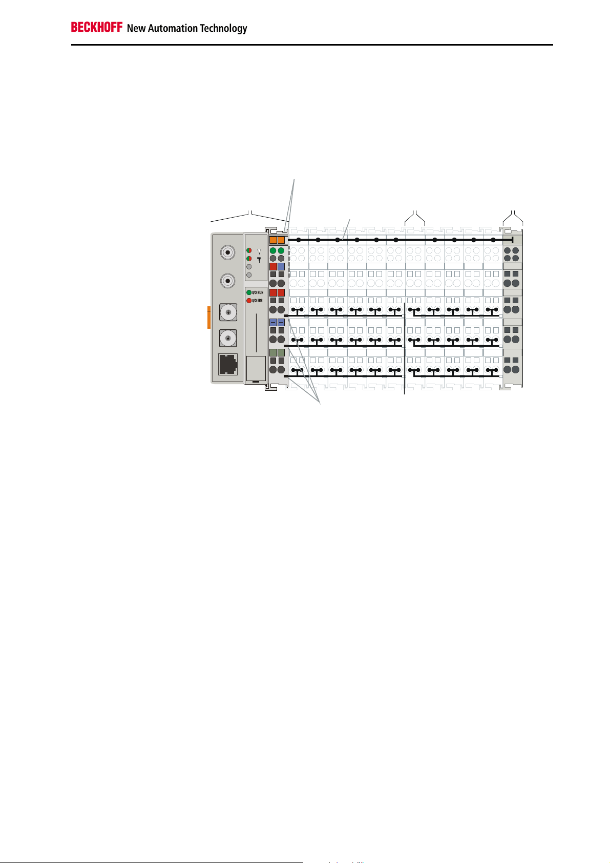
The principle of the bus
terminal
Three power contacts pass the operating power to the following terminals.
You can use power input terminals to subdivide the terminal row as desired
into groups, each with a separate power supply. These power input terminals are not taken into account for addressing the terminals, you can insert
them at any position along the terminal row.
You can install up to 64 terminals on a terminal row, including power input
terminals and the end terminal.
bus coupler for the input Bus end
BK7000 bus coupler terminal
terminal
Terminal bus
ControlNet
x1
5
6
4
7
3
8
2
9
0
x10
5
6
4
7
3
8
2
9
0
00X0
A
B
24V
0V
+ +
BK7000
BECKHOFF
PE
PE
Bus couplers for various
fieldbus systems
PotentialPower
You can use a variety of bus couplers to attach the electronic terminal row
quickly and easily to the various fieldbus systems, and you can also subsequently convert to a different fieldbus system. The bus coupler deals with
all the necessary monitoring and control tasks for operating the attached
bus terminals, indeed all the operation and configuration of the bus terminals is carried out via the bus coupler. The fieldbus, K bus and I/O level are
electrically isolated.
If the exchange of data across the fieldbus is temporarily interrupted, logic
states are preserved, digital outputs are cleared and analog outputs revert
to a reset value which can be individually configured for each output when
the equipment is set up.
5 BK 7000
Page 7
Basic information
Bus coupler / power contacts
+
PE
PE
8
7
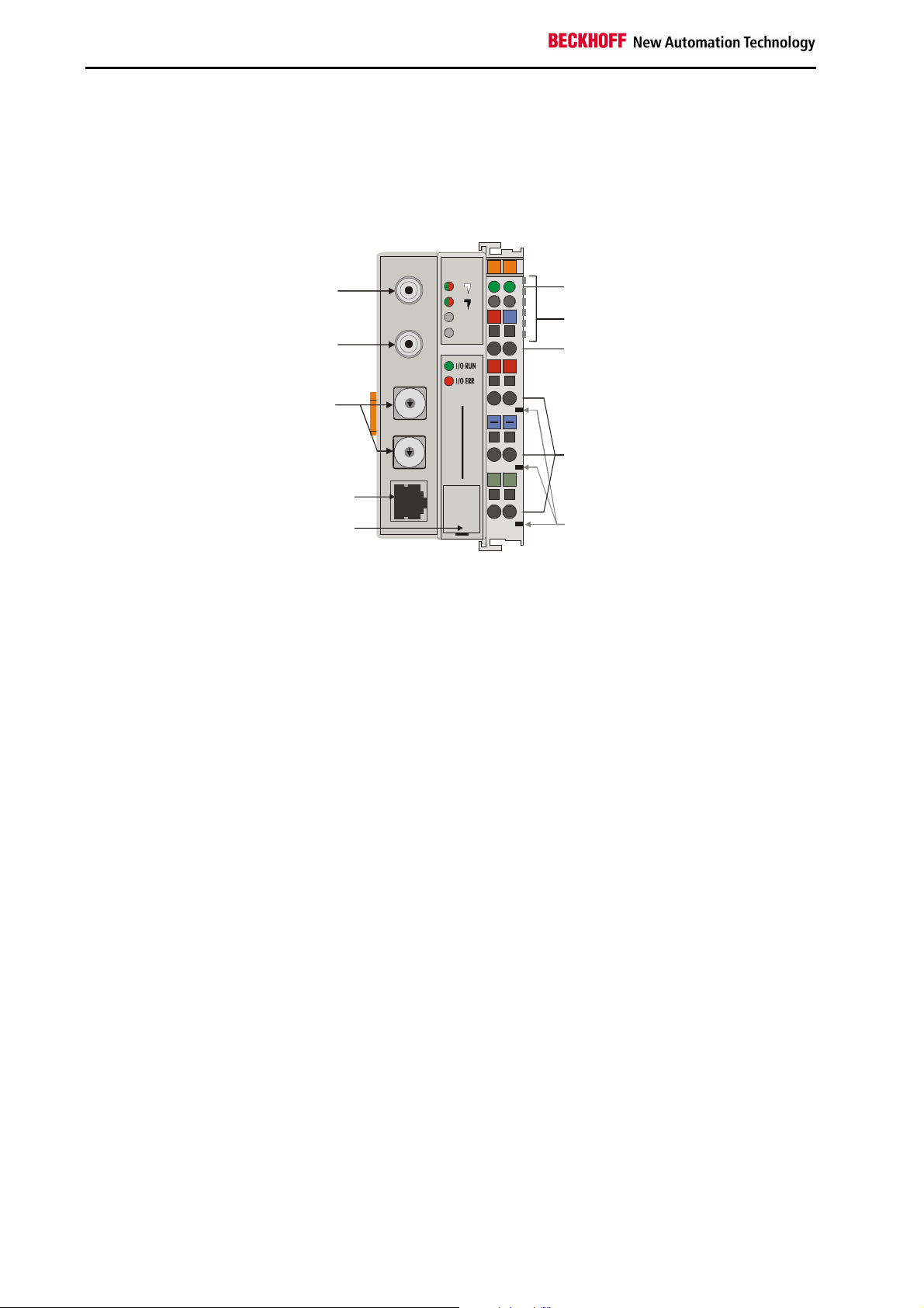
The interfaces
There are six ways of making a connection to a ControlNet bus coupler.
These interfaces are designed as plug connections and spring terminals.
The ControlNet coupler
BK7000
Field Bus
Connector A
ControlNet
A
B
00X0
24V
0V
Power LEDs
Terminal bus
Field Bus
Connector B
Address
Selector
Network Access
+
x1
5
6
4
7
3
8
2
9
1
0
x10
5
6
4
3
2
9
1
0
BK7000
BECKHOFF
Power supply bus coupler
24 V DC / GND
Input
power contacts
Port (NAP)
Configuration
Interface
power contacts
24 V DC on the topmost
terminals
Power supply
The bus couplers need an operating power of 24 V DC which is connected
via the topmost spring terminals, labeled "24 V” and "0 V”. This power supply serves not only the electronic components of the bus coupler but (via
the K bus) also the bus terminals. The power supply of the bus coupler
circuitry and that of the K-bus (Terminal bus) are electrically isolated from
the voltage of the field level.
Lower 3 terminal pairs for
power input
maximum 24 V
maximum 10 A
Power supply to the power contacts
The six lower connections with spring terminals can be used to supply
power to the peripherals. The spring terminals are connected in pairs to the
power contacts. The power supply to the power contacts has no connection to the power supply of the bus couplers. The power input is designed
to permit voltages up to 24 V. The pair-wise arrangement and the electrical
connection between the feed terminal contacts makes it possible to loop
through the wires connecting to different terminal points. The load on the
power contact may not continuously exceed 10 A. The current capacity
between two spring terminals is the same as the capacity of the connecting
wires.
Spring contacts at the side
Power contacts
On the right-hand side face of the bus coupler are three spring contacts
which are the power connections. The spring contacts are recessed in slots
to prevent them from being touched. When a bus terminal is connected,
the blade contacts on the left-hand side of the bus terminal are connected
to the spring contacts. The slot and key guides at the top and bottom of the
bus couplers and bus terminals ensure reliable location of the power contacts.
Control-Net connectors
Fieldbus connection
On the left-hand side there are two ControlNet connectors A and B and a
NAP-Port. You will find a detailed description of the fieldbus interfaces in
another part of this manual (In the chapter "The transfer medium: plugs
and cables”).
BK 7000 6
Page 8
Periphery level
Bus terminals
Bus coupler
24 V DC
Serial interface under the
front flap
6 contacts at the side
3 supply groups:
fieldbus
K-bus
peripheral level
Setting up the power levels
in the bus terminal system
Configuration interface
On the lower part of the front face you will find the standard bus couplers
which are fitted with an RS232 interface. The miniature plug can be attached to a PC by means of a connection cable and the configuration software KS2000. This interface enables you to configure the analog channels.
You can also access the functionality of the configuration interface via the
fieldbus by means of the PLC interface communications.
K-bus contacts
The connections between the bus coupler and the bus terminals are effected by gold contacts at the right-hand side of the bus coupler. When the
bus terminals are plugged together, these gold contacts automatically
complete the connection to the bus terminals. The K bus is responsible for
the power supply to the electronic components of the K bus in the bus terminals, and for the exchange of data between the bus coupler and the bus
terminals. Part of the data exchange takes place via a ring structure within
the K bus. Disengaging the K bus, for example by pulling on one the bus
terminals, will break this circuit so that data can no longer be exchanged.
However, there are mechanisms in place which enable the bus coupler to
locate the interruption and report it.
Supply isolation
The bus couplers operate with three independent supplies. The input
power supplies the electrically isolated K-bus circuitry in the bus coupler
and the K-bus itself. The power supply is also used to generate the operating power for the fieldbus.
Note: All the bus terminals are electrically isolated from the K bus, so that
the K-bus is completely electrically isolated.
Basic information
Terminal bus
Field bus
7 BK 7000
Page 9
Basic information
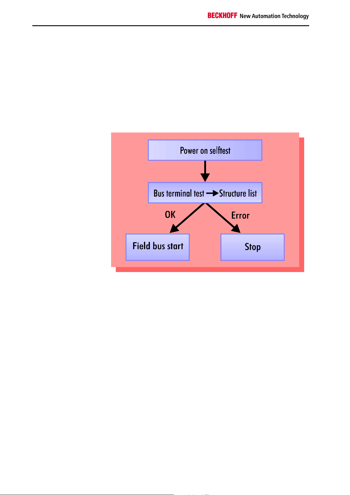
Start-up behavior of the bus
coupler
The operating modes
When it is first switched on the bus coupler carries out a self-test to check
the functions of its components and the communications of the K bus, and
while this is going on the red I/O LED will flash. When the self-test has
been completed successfully, the bus coupler will begin to test the attached bus terminals (the "bus terminal test”) and read in the configuration
from which it constructs an internal structure list, which is not accessible
from outside. If an error occurs the bus coupler will enter the operating
mode "STOP”. If the start-up sequence is completed without errors the bus
coupler will enter the mode "fieldbus start”.
The bus coupler reports the error by means of the IO-ERR-LED. Clearing
the error returns the bus coupler to its normal operating mode.
BK 7000 8
Page 10

+
+
PE
PE
1
0
0
49
12
00
.1
PE
PE
Mechanical design
The Beckhoff bus terminal system is remarkable for its compact construction and high degree of modularity. W hen you design the installation you
will need to plan for one bus coupler and some number of bus terminals.
The dimensions of the bus couplers do not depend on the fieldbus system.
If you use large plugs, for example like some of the bus plugs used for the
Profibus, they may protrude above the overall height of the cabinet.
Dimensions of a
bus coupler
ControlNet
A
B
Basic information
00X0
24V
0V
E0
.0
Assembly and connections
x1
5
6
4
7
94
3
8
2
9
1
0
x10
5
6
4
7
3
8
2
9
1
0
BK7000
BECKHOFF
+ +
The overall width of the construction is the width of the bus coupler, including the bus end terminal, plus the width of the installed bus terminals. The
bus terminals are 12 mm or 24 mm wide, depending on their function. Depending on the gauge of cables used the overall height of 68 mm may be
overstepped by about 5 mm to 10 mm by the cables at the front.
It takes only a slight pressure to latch the bus coupler and the various bus
terminals onto a supporting 35mm C rail and a locking mechanism then
prevents the individual housings from being removed. You can remove
them without effort if you first release the latching mechanism by pulling the
orange tab. You should carry out work on the bus terminals and the bus
coupler only while they are switched off: if you plug or unplug components
while the power is on you may briefly provoke some undefined state (and,
for instance, reset the bus coupler).
You can attach up to 64 bus terminals in series on the right-hand side of
the bus coupler. When you assemble the components, make sure that you
mount the housings so that each slot comes together with the corresponding key. You cannot make any functional connections merely by pushing
the housings together along the supporting track. When they are correctly
mounted there should be no appreciable gap between the adjacent housings.
The right-hand side of a bus coupler is mechanically similar to a bus terminal. There are eight connections on the top which can be used to connect
to thick-wire or thin-wire lines. The connection terminals are spring loaded.
You open a spring terminal by applying a slight pressure with a screwdriver
or other pointed tool in the opening above the terminal and you can then
insert the wire into the terminal without any obstruction. When you release
the pressure the terminal will automatically close and hold the wire securely and permanently.
9 BK 7000
Page 11

Basic information
Insulation test
PE power contacts
The connection between bus couplers and bus terminals is automatically
effected by latching the components together. The K bus is responsible for
passing data and power to the electronic components of the bus terminals.
In the case of digital bus terminals, the field logic receives power via the
power contacts. Latching the components together has the effect that the
series of power contacts constitutes a continuous power track. Please refer
to the circuit diagrams of the bus terminals: some bus terminals do not loop
these power contacts through, or not completely (e.g. analog bus terminals
or 4-channel digital bus terminals). Each power input terminal interrupts the
series of power contacts and constitutes the beginning of a new track. The
bus coupler can also be used to supply power to the power contacts.
The power contact labeled "PE” can be used as protective earth or ground.
This contact stands proud for safety reasons and can carry short-circuit
currents of up to 125A. Note that in the interests of electromagnetic compatibility the PE contacts are capacitively connected to the supporting
track. This may lead to spurious results and even damage to the terminal
when you test the insulation (e.g. insulation test for breakdown using a
230V mains supply to the PE line). You should therefore disconnect the PE
line on the bus coupler while you carry out insulation tests. You can disconnect other power supply points for the duration of the test by drawing
the power supply terminals out from the remaining row of terminals by at
least 10mm. If you do this, there will be no need to disconnect the PE connections.
The protective earth power contact ("PE”) may not be used for any other
connections.
BK 7000 10
Page 12

Electrical data
The electrical data specific to the fieldbus is given in this chapter. The following table lists an overview of all data:
Technical data BK7000
Voltage supply
Input current
Starting current
Output current K bus
Configuration possibility
Number of bus terminals
Digital peripheral signals
Analog peripheral signals
Peripheral bytes
Bus connection
Baud rates
Voltage power contact
Current load power con.
Max. voltage capacity
Weight approx.
Operating temperature
Storage temperature
Relative humidity
Vibration /shock resistance
EMC resistance burst / ESD
Orientation for mounting
Type of fuse
24 V DC (20 V...29 V DC)
70 mA + (total K-Bus current)/4
500 mA max.
2.5 x continuos current
1750 mA max.
by KS2000 or the controller
64
256 inputs/outputs
256 inputs/outputs
512 bytes I and 512 bytes O
Two BNC-connectors (ControlNet A and B) and 1 NAP-Port
5 MBaud (ControlNet V1.5)
24V DC / AC max.
10 A max.
500 Veff (power contact / supply voltage/field bus)
170g
0°C ... +55°C
-20°C ... +85°C
95% non-condensing
conforms to IEC 68-2-6 / IEC 68-2-27
conforms to EN 50082 (ESD,Burst) / EN50081
Any
IP20
Current consumption on the
K-Bus
For operation of the K-bus electronics, the bus terminals require energy
from the K-bus that is supplied by the bus coupler. Refer to the catalog or
the corresponding data sheets of the bus terminals for details of the K-bus
current consumption. In doing so, pay attention to the maximum output
current of the bus coupler that is available for powering the bus terminals.
Using a special power supply terminal (KL9400), power can be fed back
into the K-bus at any chosen point. If you wish to use a power supply terminal, please contact Beckhoff’s technical support. .
Basic information
11 BK 7000
Page 13

Basic information
The peripheral data in the process image
When the bus coupler is first switched on it determines the configuration of
the attached input/output terminals and automatically assigns the physical
slots of the input/output channels to the addresses in the process image.
The bus coupler sets up an internal list of assignments in which each of the
input and output channels has a specific position in the process image. A
distinction is made here between input and output and between bit-oriented
(digital) and byte-oriented (analog, or complex) signal processing.
It also forms two groups, whereby one contains only inputs and the other
only outputs. In each group, the byte-oriented channels take the lowest
addresses, in ascending order, and these are then followed by the bitoriented channels.
Digital signals
(bit-oriented)
Digital signals are bit-oriented. This means that one bit of the process image is assigned to each digital channel. The bus coupler sets up a block of
memory containing the current input bits and arranges to immediately write
out the bits from a second block of memory which belongs to the output
channels.
The precise assignment of the input and output channels to the process
image of the control unit is explained in detail in the Appendix by means of
an example.
Analog signals
(byte-oriented)
The processing of analog signals is always byte-oriented and analog input
and output values are stored in memory in a two-byte representation. The
values are held as "SIGNED INTEGER” or "twos-complement”. The digit
"0” represents the input/output value "0V”, "0mA” or "4mA”. When you use
the default settings, the maximum value of the input/output value is given
by "7FFF” hex. Negative input/output values, such as -10V, are represented as "8000” hex and intermediate values are correspondingly proportional to one another. The full range of 15-bit resolution is not realized at
every input/output level. If you have an actual resolution of 12 bits, the
remaining three bits have no effect on output and are read as "0” on input.
Each channel also possesses a control and status byte in the lowest value
byte. If the control/status byte is mapped in the control unit has to be configured in the master configuration software. An analog channel is represented by 2 bytes user data in the process image.
Special signals and
interface
A bus coupler supports bus terminals with additional interfaces, such as
RS232, RS485, incremental encoder, etc.. These signals can be regarded
in the same way as the analog signals described above. A 16-bit data
width may not be sufficient for all such special signals; the bus coupler can
support any data width.
Default assignment of
inputs and outputs to the
process image
When the bus coupler is first switched on it determines the number of attached bus terminals and sets up a list of assignments. This list distinguishes between analog channels and digital channels and between input
and output; which are grouped separately. The assignments begin immediately to the left of the bus coupler. The software in the bus coupler creates the assignment list by collecting the entries for the individual channels
one at a time, counting from left to right. These assignments distinguish
four groups:
Function type of the channel Assignment level
1.
2.
3.
4
Analog outputs byte-wise assignment
Digital outputs bit-wise assignment
Analog inputs byte-wise assignment
Digital inputs bit-wise assignment
BK 7000 12
Page 14

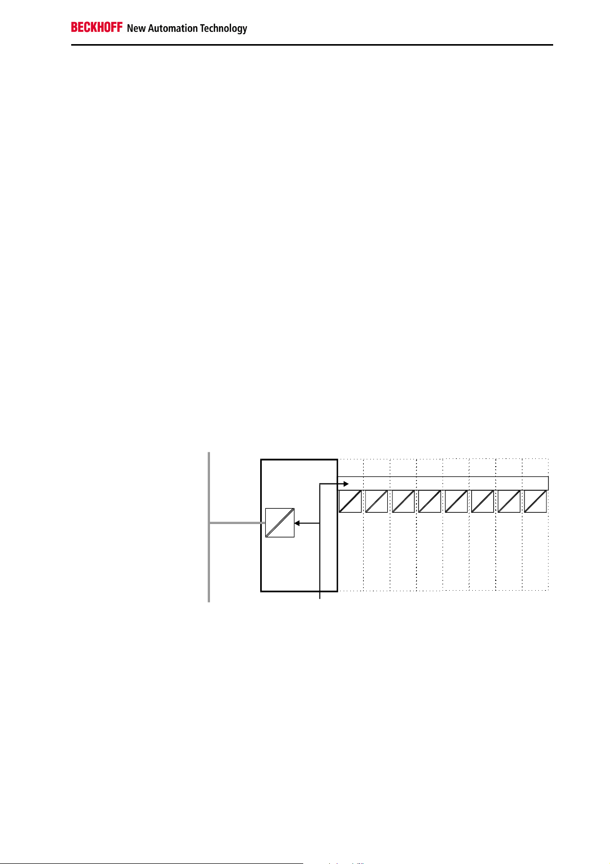
Analog inputs/ouputs are representative of other complex multi-byte signal
bus terminals (RS232, SSI sensor interface, ...)
Overview of the subdivision of the process image in the bus coupler:
Output data in the
bus coupler
Ox+1
O0
...
byte-oriented data
...
Ox
bit-oriented data
Ox+y
Input data in the
bus coupler
Ix+1
I0
...
byte-oriented data
...
Ix
...
bit-oriented data
...
Ix+y
Data consistency
Data which contains no contradictions is said to be consistent. The following consistency is required here: 1. The high byte and low byte of an analog value (word consistency), 2. The control/status byte and the corresponding parameter word for accessing the register. The interaction of the
peripherals with the control unit means that data can initially be guaranteed
consistent only within an individual byte: the bits which make up a byte are
read in together, or written out together. Byte-wise consistency is quite
adequate for processing digital signals but is not sufficient for transferring
values longer than eight bits, such as analog values. The various bus systems guarantee consistency to the required length. It is important to use
the appropriate procedure for importing this consistent data from the master bus system to the control unit. You will find a detailed description of the
correct procedure in the User Guide of the appropriate bus system, in particular in the description of the standard master units that are installed. The
chapters of this manual which deal with the fieldbus refer to the most
common of these standard units.
Processing complex signals
All byte-oriented signal channels such as RS232, RS485 and incremental
encoder, can use byte lengths greater than two. Apart from the actual difference in length, the procedure is always comparable with that for analog
signals. In the configuration software for the bus masters of the second
generation (from around 09.96), the corresponding channel can be selected directly from the "GSD file". The configuration software automatically
ensures the settings for maintaining data consistency.
Basic information
13 BK 7000
Page 15

Basic information
Starting operation and diagnostics
When the bus coupler is first switched on it at once checks the attached
configuration. A correct start-up procedure is indicated by the red LED "I/O
ERR” going out. If this LED flashes, this indicates a fault somewhere in the
terminals. You can determine the actual error code by observing the speed
of flashing and number of flashes. This will enable you to clear the fault
quickly. You will find a detailed description in the chapter "The diagnostic
LEDs”.
The diagnostic LEDs
The bus coupler has a status display consisting of two groups of LEDs.
The upper group has four LEDs which indicate the mode of the installed
fieldbus. The significance of these "fieldbus status LEDs” is explained in
the appropriate chapters of this manual; they correspond to the usual displays for fieldbuses.
There are two more green LEDs at the top right-hand side of the bus coupler to indicate the supply voltage. The left-hand LED shows the 24V supply of the bus coupler. The left-hand LED shows the supply to the power
contacts.
Local errors
Two LEDs, the "I/O LEDs”, which are situated below the fieldbus status
LEDs described above, are used to display the operating mode of the bus
terminals and the connection to these bus terminals. The green LED lights
up to indicate error-free operation, where "error-free” implies that communication with the fieldbus system is also operating correctly. The red LED
flashes at two different rates to indicate a fault, whereby the specific error
is encoded in the pattern of flashes, as follows.
Code of flashes
Rapid flashing
First slow sequence
Second slow sequence
Start of the error code
Type of error
Location of error
Error
Error co-
1 pulse
2 pulses
3 pulses
4 pulses
5 pulses
>= 6 pulses
Error argument Description
de
0
1
2
0
n (n > 0)
0 Terminal bus command error
0
n
N Terminal bus error during register commu-
ControlNet specific, will be described later
EEPROM checksum error
I/0 line buffer overflow
Unknown data type
Programmed configuration
Invalid table entry/bus coupler
Invalid table comparison (terminal n)
Terminal bus data error
Rupture point after terminal n (0: coupler)
nication with terminal n
in this document
Location of error
The number of flashes corresponds to the position of the last bus terminal
before the error, not counting passive bus terminals such as power input
terminals.
The bus coupler will carry on flashing the error code even when you have
cleared the fault and its operating mode will remain at "Stop”. The only way
to restart the bus coupler is by switching the power supply off and on
again.
You should not plug or unplug bus terminals from the series without first
turning off the power. The circuitry of the bus terminals and the bus coupler
is largely protected against damage, but if you modify the assembly while it
is under power, malfunctions and damage cannot be ruled out.
BK 7000 14
Page 16

If a fault occurs during normal operation, the error code will not be output
on the LEDs until the bus coupler has been requested to diagnose the bus
terminals. This diagnostic request is generated after the equipment is
switched on.
Fieldbus errors
The fieldbus status LEDs A and B indicate the current ControlNet bus
status of the corresponding channel. The other two LEDs are reserved for
the future.
Priority indicator state how to view cause
Highest
Lowest
both steady off viewed together reset or no power
(1)
2
both steady red viewed together failed link interface
3
alternating red /
green
4
alternating red /
off
5
steady off viewed independently channel disabled or channel not supported
6
flashing red /
green
7
flashing red / off viewed independently link fault or no MAC frames received
8
flashing green /
off
steady green viewed independently normal operation
(9)
viewed together self test
viewed together bad node configuration (such as duplicate MAC ID)
viewed independently invalid link configuration
viewed independently temporary channel error, or listen-only
Please note that there is an association between the green I/O LED and
the fieldbus. The I/O LED lights up when access is made to the internal K
bus. The green I/O LED is not lit until data begins to be exchanged via the
fieldbus.
The bus coupler does, however, interrogate the configuration of the bus
terminals after power on and does not exchange any data with the terminals. That is to say, the red I/O LED goes off after an error-free start up
without the green I/O LED having to light up. Then, the green I/O LED does
not light up until data transfer is begun via the field bus.
If a terminal bus error occurs during operation, the procedure followed conforms to the reaction to the terminal bus errors parameterisation. If the
terminal bus error already occurs during start up, the slave does not assume ControlNet data transfer.
Basic information
15 BK 7000
Page 17

Basic information
1
2
Run times and reaction times
Transfer of the signals from the input to the controller and from the control-
ler to the outputs requires a run time. This is composed of various components. Transfer from the controller to the scanner, transfer through the
ControlNet and transfer from the bus coupler to the outputs. This applies
analogously to the return distance.
Controller / Scanner
Please refer to the data provided by the scanner manufacturer for details of
the reaction time from the controller to the master. These times are comparatively short and normally do not need to be considered.
The reaction time on the ControlNet depends on the NUT and the transfer
rate
K-Bus reaction time
The reaction time on K-Bus is determined by movement and backing up of
the data. The following table contains measured values for typical setups.
Extrapolation to larger quantities is possible.
Terminals fitted on the bus coupler Run time on the K-bus
Digital
OUT
4 0 0
8 0 0
12 0 0
16 0 0
20 0 0
24 0 0
28 0 0
32 0 0
0 4 0
0 8 0
0 12 0
0 16 0
0 20 0
0 24 0
0 28 0
0 32 0
4 4 0
8 8 0
12 12 0
16 16 0
20 20 0
24 24 0
28 28 0
32 32 0
4 4
4 4
Digital
IN
Analog
IN/OUT
(KL3202)
(KL3202)
T_Zyklus
(us)
150
170
170
200
200
220
220
245
150
180
180
200
200
230
230
250
170
195
220
250
275
300
325
350
630
700
BK 7000 16
Page 18

ControlNet coupler BK7000 in the ControlNet
ControlNet coupler BK7000 in the ControlNet
Introducing the system
The deterministic control network is a serial communication system for
communication between devices that wish to exchange time-critical application information in a deterministic and predictable manner. These devices include simple I/O devices, such as sensors/actuators as well as complex control devices such as robots, programmable logic controllers, welders, process controllers, etc. Unlike general-purpose communication systems that rely on the destination delivery model, this network uses the producer/consumer model. The producer/consumer model allows the exchange of time-critical application information between a sending device
(e.g., the producer) and many receiving devices (e.g., the consumers) without the need to send the data multiple times to multiple destinations. This
is accomplished by attaching a unique identifier to each piece of application information that is being produced onto the network medium. Any device that requires a specific piece of application information simply filters the
data on the network medium for the appropriate identifier. Many devices
can receive the same produced piece of application information from a
single producing device. The deterministic control network provides a high
degree of protocol efficiency by utilising an implied token passing mechanism. This mechanism allows all devices equal access to the network without the network overhead associated with passing a “token” to each device granting it permission to send data. The protocol utilises a time-based
Scheduling mechanism that provides network devices with deterministic
and predictable access to the medium while preventing network collisions.
This scheduling mechanism allows time-critical data, which is required on a
periodic, repeatable and predictable basis, to be produced on a predefined
schedule without the loss of efficiency associated with continuously requesting or “polling” for the required data. The network protocol supports
an additional mechanism that allows data that is not time-critical in nature
or that is only required on a occasional basis to utilise any available network time. This unscheduled data is transmitted after the production of the
time-critical data has been completed and before the beginning of the next
scheduled production of time-critical data.
17 BK 7000
Page 19

ControlNet coupler BK7000 in the ControlNet
The transfer medium: plugs and cables
Physics of the transmission
Setting the station
Addresses
Address selector
The physical data transfer is defined in the ControlNet standard.
The BK7000 supports redundant media access with the two BNC connectors A and B. Additionally a monitor or configurating system can be connected over the NAP-Port.
The station address is set by way of the rotary switches on the left of the
bus coupler. The address is set as a decimal number. The top rotary switch
stands for the units position and the bottom one stands for the tens position
of the address. (Example: station address 18: bottom rotary switch = 1, top
rotary switch = 8). To ensure that the rotary switch setting is saved by the
BK7000 it must be reset (by briefing interrupting the power supply or by
means of a software reset).
Configuring the master
The assembly object of the BK7000 represents the process image buffer of
the terminal bus inputs and outputs. The data of this buffer can be sent or
received over a single connection. Assembly objects are used to produce
(terminal bus inputs) and/or consume (terminal bus outputs) data to/from
the network.
So the inputs and ouputs of the terminals will be connected to the ControlNet with the assembly object. All output data will be sent from the scanner
in one scheduled telegram and all input data will be sent to the scanner in
another scheduled telegram.
BK 7000 18
Page 20

To set up this connection, the following parameters of the FwdOpenservice have to be adjusted:
Net O->T connection
parameters
Net T->O connection
parameters
Transport class /
trigger
Connection path
network connection type Multicast
fixed/variable Fixed
priority Scheduled priority
size No of bytes (word-aligned) of the terminal bus output
network connection type Point-To-Point
fixed/variable Fixed
priority Scheduled priority
size No of bytes (word-aligned) of the terminal bus input
client / server Client
transport type Cyclic
transport class Class 1
class 0x04
connection point inputs 0x00
connection point outputs 0x00
electronic key, vendor ID 0x006C
electronic key, product ty-
pe
electronic key, product co-
de
ControlNet coupler BK7000 in the ControlNet
data (depending on the calculating rules for terminal
bus input and output data) + 4 bytes scanner status +
2 bytes transport header
data (depending on the calculating rules for terminal
bus input and output data) + 4 bytes adapter status + 2
bytes transport header
0x0080
0x1B58
19 BK 7000
Page 21

ControlNet coupler BK7000 in the ControlNet
The status code and objectic specific status code of the FwdOpenResponse can report the following codes:
Status
code
0x00
0x01
0x01
0x01
0x01
0x01
0x25
0x25
0x25
0x05
0x01
0x01
0x01
0x01
0x01
0x01
0x01
0x01
0x01
0x01
0x06
0x01
0x01
0x01
0x01
Object specific
status code
Not available Connection successful Off
0x0100 Connection already in use Fast, 8*slow, 1*slow
0x0113 Connection Manager out of connections Fast, 8*slow, 2*slow
0x0108 Unsupported connection type Fast, 8*slow, 3*slow
0x0103 Transport type not supported Fast, 8*slow, 4*slow
0x0117 Nonexistant instance number Fast, 8*slow, 5*slow
0x0114 Electronic key in IOI failed (Vendor ID) Fast, 8*slow, 6*slow
0x0115 Electronic key in IOI failed (Product type) Fast, 8*slow, 7*slow
0x0114 Electronic key in IOI failed (Product code) Fast, 8*slow, 8*slow
0x0000 invalid class Fast, 8*slow, 9*slow
0x0400 Terminal bus fault Fast, 8*slow, 10*slow
0x0109 Connection size mismatch Fast, 8*slow, 11*slow
0x011A Application out of connections Fast, 8*slow, 12*slow
0x1000 Bad config data size Fast, 8*slow, 13*slow
0x1001 Bad config data word 0 Fast, 8*slow, 14*slow
0x1002 Bad config data word 1 Fast, 8*slow, 15*slow
0x1003 Bad config data word 2 fast, 8*slow, 16*slow
0x1004 Bad config data word 3 fast, 8*slow, 17*slow
0x1010 Config buffer overflow fast, 8*slow, 18*slow
0x0315 Invalid segment in path fast, 9*slow, 1*slow
0x0000 Not all expected data sent in the connection path fast, 9*slow, 1*slow
0x0110 Connection unconfigured step 1 fast, 9*slow, 3*slow
0x0110 Connection unconfigured step 2 fast, 9*slow, 4*slow
0x0110 Connection unconfigured step 3 fast, 9*slow, 5*slow
0x0110 Connection unconfigured step 4 fast, 9*slow, 6*slow
Meaning Displayed by blinking
IO-ERR LED:
Config data of the Assembly object
Sending the config data is optional, but they must consist of 4 words when
sent.
Word Meaning (default value is printed in bold type)
0
Reserved: must be 0
1 Bit 0: 2-Byte-PLC-interface off (0) / on (1)
Bit 1: 2-Byte-Diag-interface off (0) / on (1)
2 Bit 0: Terminal bus auto-reset off (0) / on (1)
Bit 1: Terminal diagnosis off (0) / on (1)
Bit 4: Digital terminal diagnosis mapped to input data on (0) / off (1)
3 Bit 2: Complex terminals are mapped with data only, if possible (0) / completely (1)
Bit 3: Complex terminals are mapped in Intel- (0) / Motorola (1) format
Bit 5: Complex terminals are mapped without (0) / with ( 1) word-alignment
Bit 6: Terminal bus will be synchronous to the Receive-connection (0) / free running (1)
Undescribed bits are reserved for internal or future use and must not be
changed.
The config data are stored in the bus coupler’s registers 0..3 in table 0. If
no config data are sent, the values are read from these registers. The registers can be read and written using the bus coupler configuration software KS2000.
BK 7000 20
Page 22

Calculating rules for terminal bus input and output data
sizes
There are three options for mapping analog terminals and other complex
terminals: data only (if possible), complete without word-alignment, or
complete with word-alignment. The input and output data sizes depend on
which mapping option is chosen.
If no config data are sent when connecting the Assembly object, the
BK7000 will at first try to use the most recently used mapping option. Failing that, it will try the options in the following order, choosing the first option that will make the data sizes match with the sizes received from the
scanner. This option will then be stored in the register table.
Rule 1
Analog terminals are mapped with data only. Other complex terminals are
mapped with data only if applicable, otherwise they are mapped completely, without word-alignment.
Rule 2
All complex terminals are mapped completely, without word-alignment.
Rule 3
Analog terminals are mapped with data only, other complex terminals are
mapped with data only if applicable, otherwise they are mapped completely, with word-alignment.
Rule 4
All complex terminals are mapped completely, with word-alignment.
If config data are sent when connecting the Assembly object, the input and
output data sizes are calculated using the selected option.
If the 2-Byte-PLC-interface or the 2-Byte-Diag-interface are enabled by the
config data, 2 additional bytes of input and output data are needed for each
enabled interface.
The data of the Assembly object have the following stucture:
Offset (in bytes) Meaning Remark
0
Transport header
2
Scanner / Adapter status
6
2-Byte-PLC-interface Optional
8
2-Byte-Diag-Interface Optional
10
Complex terminals (left to right)
10 + size of complex terminals
Digital terminals (left to right)
Note that the terminal data begin at offset 8 or 6 if any or both of the optional interfaces are disabled.
ControlNet coupler BK7000 in the ControlNet
21 BK 7000
Page 23

ControlNet coupler BK7000 in the ControlNet
Configuration with RS Networx 1.06
Make sure that beckhoff.hwx is registered with regsvr32.exe. This needs to
be done only once. If you aren’t sure whether this has been done already,
skip to step 2.
Select BK7000 from the list of communication products to add it to the configuration. If the BK7000 isn’t in the list as shown, you need to perform step
1.
BK 7000 22
Open the ControlNet configuration of the controller (PLC-5/20C in the example), and insert a device connection to the BK7000.
Page 24

ControlNet coupler BK7000 in the ControlNet
Set the input and output data size for the BK7000 according to the connected terminals and the desired mapping. Set the config size to 0 for default
settings or 4 for custom settings.
Save the configuration
Configuration with RS Networx 1.03
With RS Networx 1.03 the BK7000 in standard will not be supported. The
BK7000 can be configured like an 1771 ACN®15-I/O-adapter from AllenBradley. Instead of the assembly object the BK7000 in 1771-Mode supports two objects: the rack object for digital terminals and the 1771-generic
module for anlog terminals.
The input and output size of the digital object must be the number of words
of the digital inputs/outputs.
The input and output size of the analog object must be the number of
words of the analog inputs/outputs. The same rules as for the assembly
object will be used for the analog object.
For the digital object insert a discrete rack in the ControlNet configuration,
for the analog object insert a module and select the „1771-Generic“module.
The config size in the 1771-Mode must be zero.
23 BK 7000
Page 25

Appendix
Sample arrangement of a process image in
Appendix
the bus coupler
For this configuration
the bus coupler will create
the list of assignments
shown below
Area for byte-oriented
data, analog outputs
The following example will illustrate the assignment of input/output channels to the process image. Our sample construction is to consist of the
following bus terminal components:
Position Function component on the track
POS01
POS02
POS03
POS04
POS05
POS06
POS07
POS08
POS09
POS10
POS11
POS12
POS13
POS14
POS15
POS16
POS17
POS18
POS19
POS20
POS21
Besides transfer of the user information signal, when using analog terminals the control/status byte is also available via the process image by parameterisation of a three-byte channel (see PROFIBUS-DP).
Relative byte
address
6, 7,
10, 11
Bus coupler
2-channel digital input
2-channel digital input
2-channel digital input
2-channel digital input
2-channel digital input
2-channel digital output
2-channel digital output
2-channel digital output
2-channel analog input
2-channel analog output
2-channel analog output
2-channel analog input
Power input terminal
2-channel digital input
2-channel digital input
2-channel digital input
2-channel digital output
2-channel digital output
2-channel analog output
End terminal
Bit position Process image in
the control unit
0, 1
none O0, O1 POS11
2, 3
none O2, O3 POS11
4, 5
none O4, O5 POS12
none O6, O7 POS12
8, 9
none O8, O9 POS20
none O10, O11 POS20
Position in the
block
BK 7000 24
Page 26

Area for bit-oriented data,
digital outputs
Relative byte
address
Area for byte-oriented
data, analog inputs
Relative byte
address
Area for bit-oriented data,
digital inputs
Relative byte
address
The items POS14 and POS21 are not relevant to data exchange and do
not appear in the list. If a byte is not fully used, for example O13, the bus
coupler pads its remaining bits with zeroes.
Overview of the distribution of the process image in the bus coupler:
Output data
in the bus coupler
O0
...
byte-oriented data
...
O11
O12
bit-oriented data
O13
Input data
in the bus coupler
I0
...
byte-oriented data
...
I3
I4
...
bit-oriented data
...
I5
Bit position Process image in
the control unit
12
0 O12 POS07
12
1 O12 POS07
12
2 O12 POS08
12
3 O12 POS08
12
4 O12 POS09
12
5 O12 POS09
12
6 O12 POS18
12
7 O12 POS18
13
0 O13 POS19
13
1 O13 POS19
Bit position Process image in the
control unit
0, 1
none I0, I1 POS10
2, 3
none I2, I3 POS13
Bit position Process image in the
control unit
4
0 I4 POS02
4
1 I4 POS02
4
2 I4 POS03
4
3 I4 POS03
4
4 I4 POS04
4
5 I4 POS04
4
6 I4 POS05
4
7 I4 POS05
5
0 I5 POS06
5
1 I5 POS06
5
2 I5 POS15
5
3 I5 POS15
5
4 I5 POS16
5
5 I5 POS16
5
6 I5 POS17
5
7 I5 POS17
Appendix
Position in the
block
Position in the
block
Position in the
block
25 BK 7000
Page 27

Appendix
Representation of analog signals in the
The base addresses I0 and O0 listed here are used as relative addresses
or addresses in the bus coupler. If you have an appropriate superordinate
Profibus system you can use the bus master to enter these addresses at
any desired position in the process image of the control unit. You can use
the configuration software of the master to assign the bytes to the addresses in the process image of the control unit.
process image
I/O bytes of an analog
channel in the process
image
Significance of the
control/status bytes
for accessing
the register model
In the standard case, the analog signals are presented as follows: to input
bytes or to output bytes of the process image are needed for each analog
channel. The two bytes represent the value as unsigned interger, i.e. 15
bits with the sign. The data format is used independently of the actual resolution. Example: with a resolution of 12 bits in the case of analog values in
the positive and negative value ranges, the four least significant bits are of
no importance. If the value of the analog signal is only positive, the sine bit
(bit 15, MSB) is always "0". In this case, the 12 bits of the analog value are
represented in bit 14 to bit 3. The three least significant bits are of no importance.
By configuration via the Profibus master software or the KS2000 software,
the bus coupler can represent all or individual analog channels in an extended mode. Optionally, the control and status byte of a channel can also
be inserted. The least significant byte of three bytes has control and status
functions. The other two bytes become inputs and outputs. Various operating modes can be set with the control byte. The 6 least significant bits of
the control and status byte can be used as addressing bits. Addressing
serves to read and write a register set inside the terminal. The register set
has 64 registers. The settings are stored permanently
Output byte 1 Output byte 0 Control byte
Input byte 1 Input byte 0 Status byte
BIT 7 0 = NORMAL MODE, 1 = CONTROL MODE
BIT 6
BIT 5
BIT 4
BIT 3
BIT 2
BIT 1
BIT 0
0 = READ, 1 = WRITE
Register address, MSB
Register address
Register address
Register address
Register address
Register address, LSB
BK 7000 26
Page 28

15
0
GA
Register set of an
63
analog channel
47
31
16
0 Length Type
The significance of the registers and status bytes is explained in the data
sheets for the corresponding bus terminals. The construction of the module
is identical for bus terminals with more extensive signal processing.
User area
OFF SET
IN
Factory settings
Software
version
Type
Secondary process image
Appendix
27 BK 7000
Page 29

Support and Service
Support and Service
Beckhoff and their partners around the world offer comprehensive support and service, making available
fast and competent assistance with all questions related to Beckhoff products and system solutions.
Beckhoff's branch offices and representatives
Please contact your Beckhoff branch office or representative for local support and service on Beckhoff
products!
The addresses of Beckhoff's branch offices and representatives round the world can be found on her
internet pages: http://www.beckhoff.com
You will also find further documentation for Beckhoff components there.
Beckhoff Headquarters
Beckhoff Automation GmbH
Eiserstr. 5
33415 Verl
Germany
phone: + 49 (0) 5246/963-0
fax: + 49 (0) 5246/963-198
e-mail: info@beckhoff.com
web: www.beckhoff.com
Beckhoff Support
Support offers you comprehensive technical assistance, helping you no only with the application of individual Beckhoff products, but also with other, wide-ranging services:
• support
• design, programming and commissioning of complex automation systems
• and extensive training program for Beckhoff system components
hotline: + 49 (0) 5246/963-157
fax: + 49 (0) 5246/963-9157
e-mail: support@beckhoff.com
Beckhoff Service
The Beckhoff Service Center supports you in all matters of after-sales service:
• on-site service
• repair service
•
spare parts servive
• hotline service
hotline: + 49 (0) 5246/963-460
fax: + 49 (0) 5246/963-479
e-mail: service@beckhoff.com
BK 7000 28
 Loading...