

Page 1

DeviceNet Coupler
BK5200, BK5210, LC5200
Technical Documentation
Version 1.3
2006-10-24
Page 2

Please note the following
Target group
Safety requirements
This description is only intended for the use of trained specialists in control
and automation engineering who are familiar with the applicable national
standards.
The responsible staff must ensure that the application or use of the
products described satisfy all the requirements for safety, including all the
relevant laws, regulations, guidelines and standards.
The documentation has been prepared with care. The products described are,
however, constantly under development. For that reason the documentation is not
in every case checked for consistency with performance data, standards or other
characteristics, and does not represent an assurance of characteristics in the sense
of § 459, Para. 2 of the German Civil Code. In the event that it contains technical or
editorial errors, we retain the right to make alterations at any time and without
warning. No claims for the modification of products that have already been supplied
may be made on the basis of the data, diagrams and descriptions in this
documentation.
This manual is copyrighted. Any reproduction or third party use of this protected
©
publication, whether in whole or in part, without the written permission of Elektro
Beckhoff GmbH, is forbidden.
BK52x0
Page 3

Table of contents
Table of contents
1. Foreword 4
Notes on the documentation 4
Liability Conditions 4
Delivery conditions 4
Copyright 4
Safety Instructions 5
State at Delivery 5
Description of safety symbols 5
2. Basic Principles 6
The Beckhoff Bus Terminal System 6
The interfaces 8
Power supply 8
Power contact feed points 9
Power contacts 9
Fieldbus connection 9
Configuration interface 9
K-Bus contacts 9
Electrical isolation 10
Operating modes of the Bus Coupler 11
Mechanical construction 12
Technical data 14
Peripheral data in the process image 16
Start-up procedure and Diagnostics 18
3. BK5200, BK5210, LC5200 DeviceNet 20
Introduction to the system 20
Configuring the Bus Coupler 22
Connector Pin assignment / DeviceNet connection 23
Data exchange 24
Light-emitting diodes 25
Vendor ID 26
DeviceNet Group 26
Bus cable: length, assignment 27
Electrical isolation 28
4. Appendix 29
Example: composition of a process image in the Bus Coupler 29
5. Support and Service 32
Beckhoff's branch offices and representatives 32
Beckhoff Headquarters 32
BK52x0 3
Page 4

Foreword
Foreword
Notes on the documentation
This description is only intended for the use of trained specialists in control and automation engineering
who are familiar with the applicable national standards. It is essential that the following notes and
explanations are followed when installing and commissioning these components.
Liability Conditions
The responsible staff must ensure that the application or use of the products described satisfy all the
requirements for safety, including all the relevant laws, regulations, guidelines and standards.
The documentation has been prepared with care. The products described are, however, constantly under
development. For that reason the documentation is not in every case checked for consistency with
performance data, standards or other characteristics. None of the statements of this manual represents a
guarantee (Garantie) in the meaning of § 443 BGB of the German Civil Code or a statement about the
contractually expected fitness for a particular purpose in the meaning of § 434 par. 1 sentence 1 BGB. In
the event that it contains technical or editorial errors, we retain the right to make alterations at any time
and without warning. No claims for the modification of products that have already been supplied may be
made on the basis of the data, diagrams and descriptions in this documentation.
Delivery conditions
In addition, the general delivery conditions of the company Beckhoff Automation GmbH apply.
Copyright
©
This documentation is copyrighted. Any reproduction or third party use of this publication, whether in
whole or in part, without the written permission of Beckhoff Automation GmbH, is forbidden.
4 BK52x0
Page 5
i
Foreword
Safety Instructions
State at Delivery
All the components are supplied in particular hardware and software configurations appropriate for the
application. Modifications to hardware or software configurations other than those described in the
documentation are not permitted, and nullify the liability of Beckhoff Automation GmbH.
Description of safety symbols
The following safety symbols are used in this documentation. They are intended to alert the reader to the
associated safety instructions..
This symbol is intended to highlight risks for the life or health of personnel.
Danger
This symbol is intended to highlight risks for equipment, materials or the
Attention
environment.
This symbol indicates information that contributes to better understanding.
Note
BK52x0 5
Page 6

Basic Principles
Basic Principles
Up to 64 Bus Terminals
each having 2 I/O channels
for each signal form
de-centralised wiring of the
I/O level
IPC as controller
Bus Couplers for all usual
bus systems
Standard C - rail assembly
Modularity
Display of the channel state
K-Bus
End terminal
The Beckhoff Bus Terminal System
The Bus Terminal system is the universal interface between a fieldbus
system and the sensor / actuator level. A unit consists of a Bus Coupler as
the head station, and up to 64 electronic series terminals, the last one
being an end terminal. For each technical signal form, terminals are
available each having two I/O channels, and these can be mixed in any
order. All the terminal types have the same mechanical construction, so
that difficulties of planning and design are minimised. The height and depth
match the dimensions of compact terminal boxes.
Fieldbus technology allows more compact forms of controller to be used.
The I/O level does not have to be brought to the controller. The sensors
and actuators can be wired de-centrally, using minimum cable lengths. You
can locate the controller installation anywhere within the plant. The use of
an Industrial PC as the controller means that the operating and observing
element can be implemented in the controller’s hardware. The controller
can therefore be located at an operating panel, in a control room, or at
some similar place. The Bus Terminals form the de-centralised input/output
level of the controller in the control cabinet and the subsidiary terminal
boxes. The power sector of the plant is also controlled over the bus system
in addition to the sensor/actuator level. The Bus Terminal replaces the
conventional series terminal as the wiring level in the control cabinet. The
control cabinet can have smaller dimensions.
The Beckhoff Bus Terminal system unites the advantages of a bus system
with the possibilities of the compact series terminal. Bus Terminals can be
driven within all the usual bus systems, thus reducing the controller parts
count. The Bus Terminals then behave like conventional connections for
that bus system. All the performance features of the particular bus system
are supported.
The easy, space-saving, assembly on a standard C-rail, and the direct
wiring of actuators and sensors, without cross-connections between the
terminals, standardises the installation. The consistent labelling scheme
also contributes.
The small physical size and the great flexibility of the Bus Terminal system
allows it to be used wherever a series terminal is also used. Every type of
connection, such as analog, digital, serial or the direct connection of
sensors can be implemented.
The modular assembly of the terminal strip with Bus Terminals of various
functions limits the number of unused channels to a maximum of one per
function. The presence of two channels in one terminal is the optimum
compromise of unused channels and the cost of each channel. The
possibility of electrical isolation through potential feed terminals also helps
to keep the number of unused channels low.
The integrated LEDs show the state of each channel at a location close to
the sensors and actuators.
The K-Bus is the data path within a terminal strip. The K-Bus is led through
from the Bus Coupler through all the terminals via six contacts on the
terminals‘ side walls. The end terminal terminates the K-Bus. The user
does not have to learn anything about the function of the K-Bus or about
the internal workings of the terminals and the Bus Coupler. Many software
tools that can be supplied make project planning, configuration and
operation easy.
6 BK52x0
Page 7
isolation
contacts
DeviceNet
Power supply
Potential
Basic Principles
Potential feed terminals for
electrically isolated groups
The principle of the Bus
Terminal
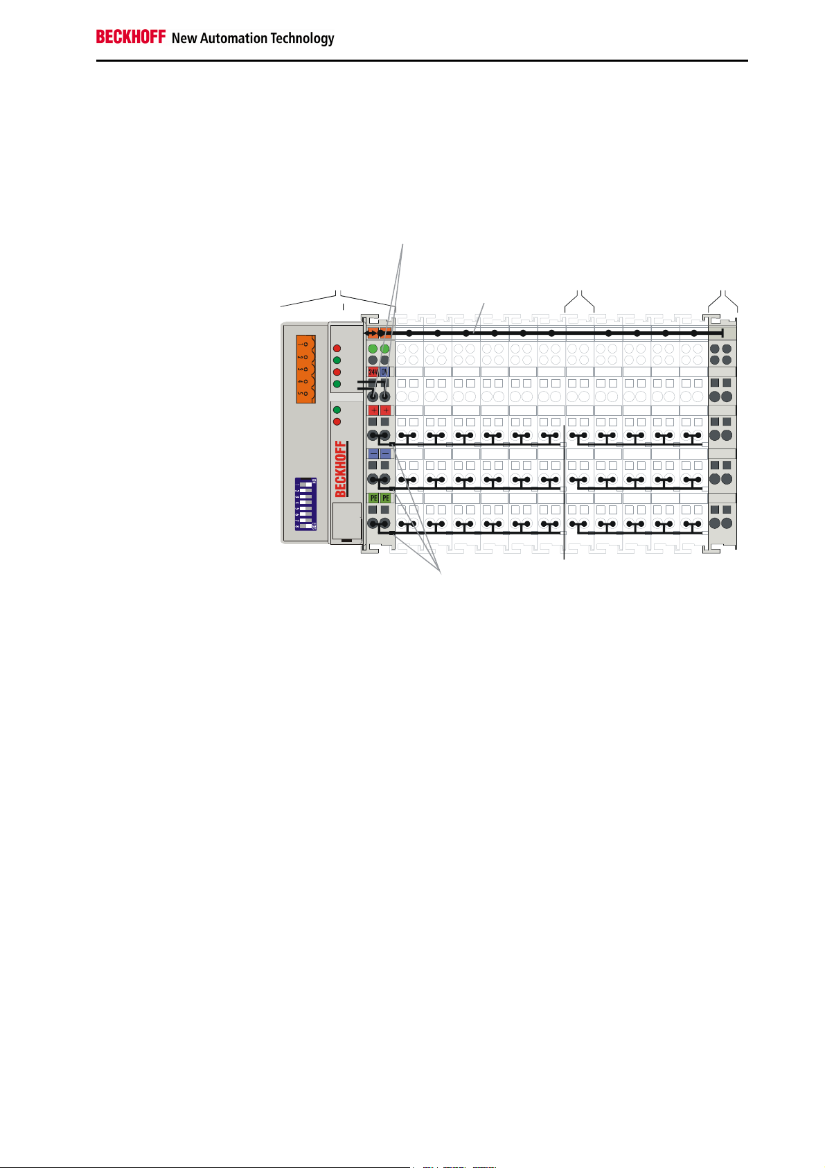
The operating voltage is passed on to following terminals via three power
contacts. You can divide the terminal strip into arbitrary isolated groups by
means of potential feed terminals. The feed terminals play no part in the
control of the terminals, and can be inserted at any locations within the
terminal strip.
Up to 64 terminals may be located in a terminal strip, including the potential
feed terminals and end terminal.
Bus Coupler for the feed Bus end
BK5200 Bus Coupler terminal
terminal
K-Bus
DeviceNet
OVERFL
MS
RUN
BUS OFF
NS
CONNECT
I/O RUN
I/O ERR
BK5200
Bus couplers for various
fieldbus systems
PotentialPower
Various Bus Couplers can be used to couple the electronic terminal strip
quickly and easily to different fieldbus systems. It is also possible to
convert to another fieldbus system at a later time. The Bus Coupler
performs all the monitoring and control tasks that are necessary for
operation of the connected Bus Terminals. The operation and configuration
of the Bus Terminals is carried out exclusively by the Bus Coupler.
Fieldbus, K-Bus and I/O level are electrically isolated.
If the exchange of data over the fieldbus fails for a time, counter states are
retained, digital outputs are cleared, and analogue outputs take a value
that can be separately configured for each output when commissioning.
BK52x0 7
Page 8
Basic Principles
Power LEDs
Bus Coupler / Power
Power supply for
C+
C-
00
X0
LC5200
Beckhoff
K-Bus
CAN-H, CAN-L
Power contacts
The DeviceNet Coupler
BK5200 / BK5210
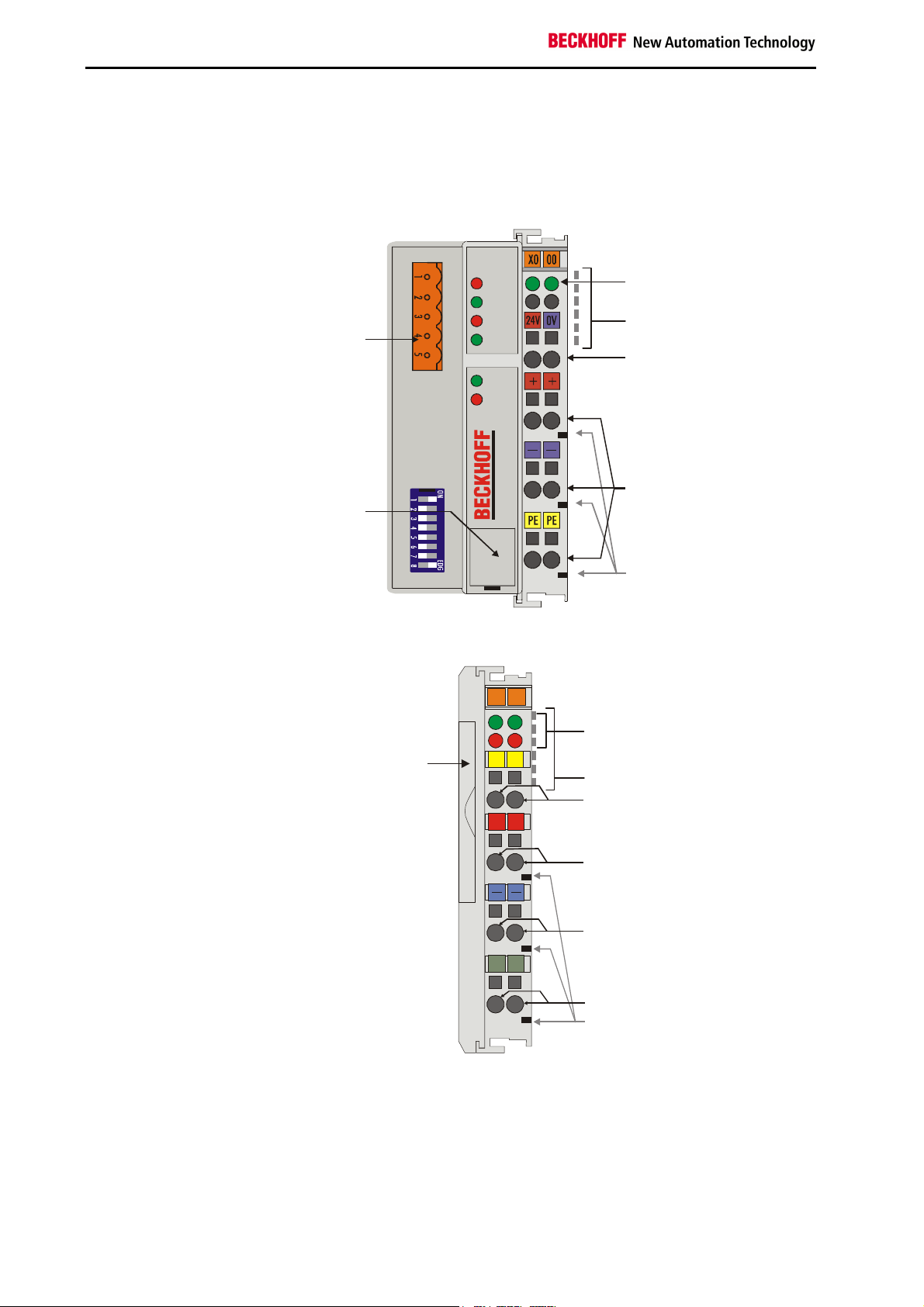
The interfaces
A Bus Coupler has six different methods of connection. These interfaces
are designed as plug connectors and as spring-loaded terminals.
DeviceNet
connector
DeviceNet
OVERFL
MS
RUN
BUS OFF
NS
CONNECT
I/O RUN
I/O ERR
contacts
K-Bus
Power supply
Bus Coupler
24 V DC / GND
The DeviceNet coupler
LC5200
ConfigurationInterface
BK5200
Input
Power contacts
Power contacts
The LC5200 Bus Coupler integrates the bus connection into the springloaded terminals.
0201
left:
fieldbus LEDs
right:
Address
K-Bus LEDs
selector
+ +
V+
Bus Coupler
and field level
V-
BK5200, BK5210:
24 V DC to the topmost
terminals “24 V” and “0 V”
8 BK52x0
S S
Screen
Power supply
The Bus Couplers require a 24 V DC supply for their operation. In the case
of the BK52x0 Bus Couplers the connection is made by means of the
upper spring-loaded terminals labelled “24 V” and “0 V”. This supply
voltage feeds not only the Bus Coupler electronics via the K-Bus, but also
the Bus Terminals. In the BK52x0 Bus Couplers the voltage supply for the
bus coupler electronics and that of the K-bus are electrically isolated from
the field level potentials.
Page 9

Basic Principles
LC5200:
24V DC to the centre
terminal pairs
Bottom 3 terminal pairs for
feed
Maximum 24 V
Maximum 10 A
Spring contacts on the side
BK5200, BK5210: 5 pin
open style connector
LC5200: Bus connection
via spring loaded terminals
Serial interface under the
front cover
6 contacts on the side
The LC5200 Bus Coupler is supplied via the two central terminal pairs. The
power contacts pass the supply voltage on to the field level.
Power contact feed points
The bottom six connections with spring-loaded terminals can be used to
feed the supply for the peripherals. The spring-loaded terminals are joined
in pairs to a power contact. The feed for the power contacts has no
connection to the voltage supply for the bus coupler (BK52x0). The design
of the feed permits voltages of up to 24 V. The assignment in pairs and the
electrical connection between feed terminal contacts allows the connection
wires to be looped through to various terminal points. The current drawn
from the power contact must not exceed 10 A for long periods. The current
rating between two spring-loaded terminals is identical to that of the
connecting wires.
Power contacts
On the right hand face of the Bus Coupler there are three spring contacts
for the power contact connections. The spring contacts are hidden in slots
so that they can not be accidentally touched. By attaching a Bus Terminal
the blade contacts on the left hand side of the Bus Terminal are connected
to the spring contacts. The tongue and groove guides on the top and
bottom of the Bus Coupler and of the Bus Terminals guarantees that the
power contacts mate securely.
Fieldbus connection
The BK52x0 Bus Couplers have a recessed front surface on the left hand
side. The DeviceNet connection plug can be inserted here. A full
description of the fieldbus interfaces is found elsewhere in this manual.
In the LC5200 Bus Coupler the bus is connected directly at the upper
terminal pair.
Configuration interface
The BK52x0 Bus Couplers have an RS232 interface at the bottom of the
front face, whereas on the LC5200 it is located under the cover on the side.
The miniature connector can be joined to a PC with the aid of a connecting
cable and the KS2000 configuration software. The interface allows the
analog channels to be configured and also permits firmware updating.
The functionality of the configuration interface can also be reached via the
fieldbus using the object attributes for the register communication.
K-Bus contacts
In order to connect the Bus Coupler and Bus Terminals the Bus Coupler
has gold contacts on the right hand side. When the Bus Terminals are
pushed together the gold contacts automatically make the connection
between the Bus Terminals. The voltage supply to the K-Bus electronics in
the Bus Terminals and the data exchange between the Bus Coupler and
the Bus Terminals is carried out by the K-Bus. A part of the data exchange
takes place via a ring structure within the K-Bus. Opening the K-Bus, e.g.
by pulling out one of the Bus Terminals, opens the ring. Data exchange is
no longer possible. Special mechanisms nevertheless allow the Bus
Coupler to identify the location of the interruption and to report it.
BK52x0 9
Page 10
Basic Principles
Periphery level
Bus Terminals
Bus Coupler
24 V DC
BK5200, BK5210:
3 potential groups:
Fieldbus
K-Bus
Peripheral level
BK5200, BK5210:
Structure of the potential
levels in the Bus Terminal
system
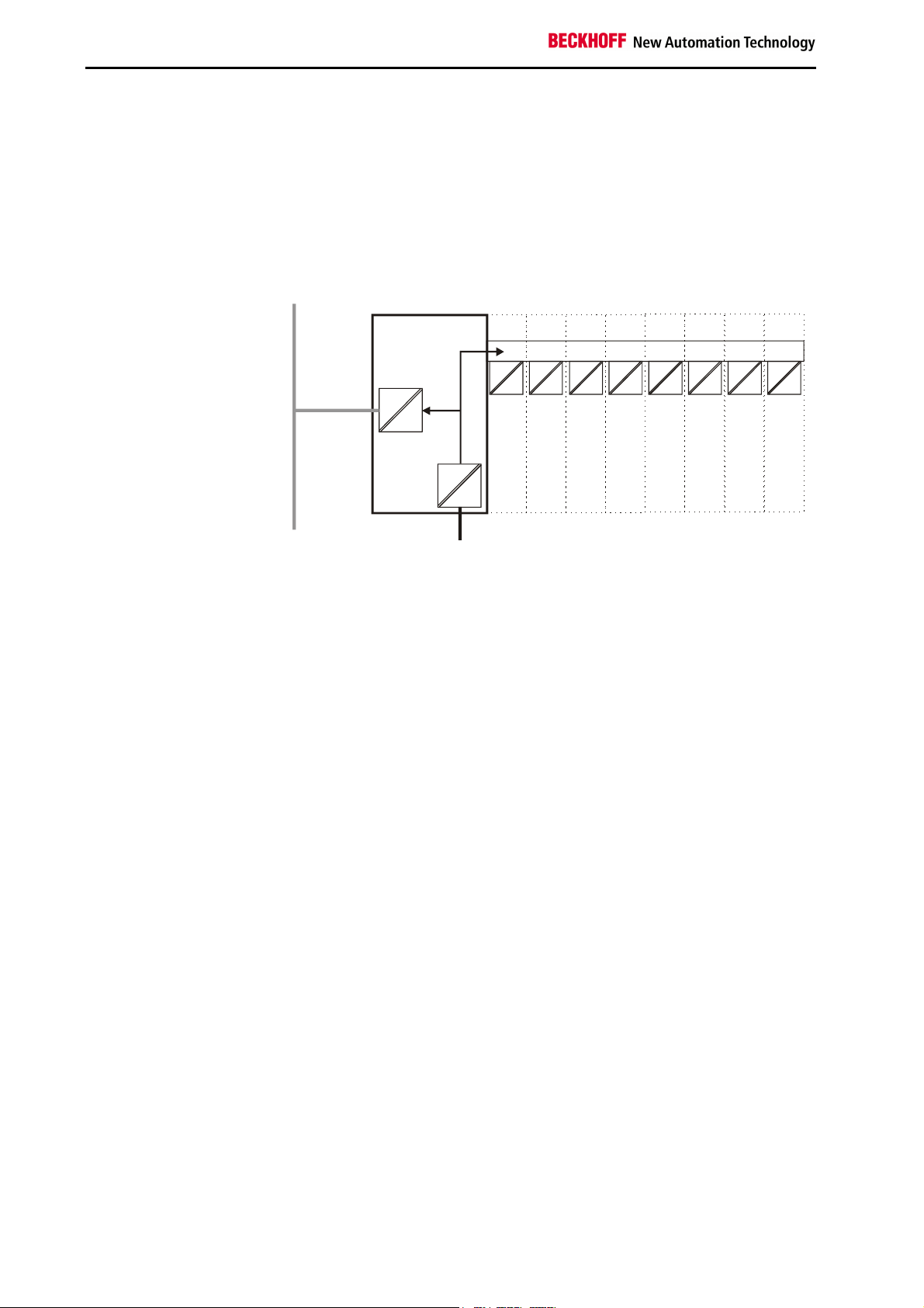
Electrical isolation
The Bus Couplers operate by means of three independent potential
groups. The supply voltage feeds the K-Bus electronics in the Bus Coupler
and the K-Bus itself, which are electrically separate. The supply voltage is
also used to generate the operating voltage for the fieldbus.
Remark: All the Bus Terminals are electrically isolated from the K-Bus. The
K-Bus is thus electrically isolated from everything else.
Fieldbus
K-Bus
LC5200:
The LC5200 does not provide electrical isolation from the fieldbus and
peripheral level. If the peripheral level nevertheless needs to have an
electrically isolated implementation, this can easily be achieved through the
use of isolating terminals (KL9xxx).
10 BK52x0
Page 11

Bus Terminal test Structure list
Start-up behaviour of the
Bus Coupler
Operating modes of the Bus Coupler
Immediately after being switched on, the Bus Coupler checks, in the
course of a “self test”, all the functions of its components and the
communication on the K-Bus. The red I/O LED blinks while this is
happening After completion of the self-test, the Bus Coupler starts to test
the attached Bus Terminals (the ”Bus Terminal Test”), and reads in the
configuration. The Bus Terminal configuration is used to generate an
internal structure list, which is not accessible from outside. In case of an
error, the Bus Coupler enters the “STOP“ state. Once the start-up has
completed without error, the Bus Coupler enters the "fieldbus start" state.
Basic Principles
Power on selftest
The Bus Coupler reports the error to the master by means of the status
byte in the DeviceNet diagnostics (see section "Data exchange"). Clearing
the error returns the Bus Coupler to its normal operating mode.
BK52x0 11
Page 12

Basic Principles
02
01
+
+
S
S
C+
C-
00
X0
LC5100
Beckhoff
21
Mechanical construction
The system of the Beckhoff Bus Terminals is characterised by low physical
volume and high modularity. When planning a project it must be assumed
that at least one Bus Coupler and a number of Bus Terminals will be used.
The mechanical dimensions of the Bus Couplers are independent of the
fieldbus system.
Bus Coupler dimensions
Assembly and connection
The total width in practical cases is composed of the width of the Bus
Coupler with the bus end terminal and the width of the Bus Terminals in
use. Depending on function, the Bus Terminals are 12 or 24 mm wide. The
front wiring increases the total height of 68 mm by about 5 to 10 mm,
depending on the wire thickness.
The Bus Coupler and all the Bus Terminals can be clipped, with a light
press, onto a 35 mm C-mounting rail. A locking mechanism prevents the
individual housings from being pulled off again. For removal from the
mounting rail the orange coloured tension strap releases the latching
mechanism, allowing the housing to be pulled off the rail without any force.
Work should only be carried out on the Bus Terminals and the Bus Coupler
when switched off. Pulling out and inserting under power can cause
undefined states to be temporarily caused. (A reset of the Bus Coupler, for
example.)
Up to 64 Bus Terminals can be attached to the Bus Coupler on the right
hand side. When plugging the components together, be sure to assemble
the housings with groove and tongue against each other. A properly
working connection can not be made by pushing the housings together on
the mounting rail. When correctly assembled, no significant gap can be
seen between the attached housings.
The right hand part of the Bus Coupler can be compared to a Bus
Terminal. Eight connections on the top permit connection with solid or fine
wires. The connection is implemented with the aid of a spring device. The
spring-loaded terminal is opened with a screwdriver or rod, by exerting
gentle pressure in the opening above the terminal. The wire can be
inserted into the terminal without any force. The terminal closes
automatically when the pressure is released, holding the wire securely and
permanently.
12 BK52x0
Page 13

Basic Principles
Insulation testing
PE power contacts
The connection between the Bus Coupler and the Bus Terminals is
automatically realised by pushing the components together. The transfer of
the data and the supply voltage for the intelligent electronics in the Bus
Terminals is performed by the K-Bus. The field electronics are supplied in
the case of the digital Bus Terminals through the power contacts. Plugging
together the power contacts creates a supply rail. Note the circuit diagrams
for the Bus Terminals, since some Bus Terminals do not loop these power
contacts through, or only do so partially (e.g. analog Bus Terminals or 4
channel digital Bus Terminals). The potential feed terminals interrupt the
power contacts, and represent the start of a new supply rail. The Bus
Coupler can also be made use of to feed the power contacts.
The power contact labelled “PE” can be used as a protective earth. For
safety reasons this contact mates first when plugging together, and can
ground short-circuit currents of up to 125 A. Note that, for reasons of
electromagnetic compatibility, the PE contacts are capacitively coupled to
the mounting rail. This can both lead to misleading results and to damaging
the terminal during insulation testing. (e.g.: breakdown of the insulation
from a 230 V power user to the PE conductor.) The PE conductor to the
Bus Coupler must be disconnected for the insulation testing. In order to
uncouple further feed locations for the purposes of testing, the feed
terminals can be pulled at least 10 mm out from the connected group of
other terminals. In that case, the PE conductors do not have to be
disconnected.
The “PE” power contact must not be used for other potentials.
BK52x0 13
Page 14

Basic Principles
Technical data
Electrical data
The DeviceNet couplers differ in the level of the facilities they offer. The
fieldbus-specific electrical data is listed in this section. The following data
differs between the Standard, the Economy and the Low-Cost versions
(BK5200, BK5210 and LC5200). Compatibility with DeviceNet is ensured in
all cases, but the Economy and Low-Cost versions have a restricted
number of I/O points. This is why it is not possible to connect anything
other than digital inputs and outputs.
System data DeviceNet (BK5200, BK5210, LC5200)
Number of I/O modules
Transmission medium
Length of the cable
Transmission rate
Operating modes
Device Net type
64
Screened, twisted copper wire with power supply, 5-pin
500 m 250 m 100 m
125 kbaud 250 kbaud 500 kbaud
Bit Strobe, Polling, Cyclic, Change of State (COS)
Communications adapter
Technical data BK5200 BK5210
Number of Bus Terminals
Digital peripheral signals
Analog peripheral signals
Possibility of configuration
Maximum number of bytes
Bus connection
Power supply
Input current
Starting current
Recommended back-up fuse
K-Bus power supply up to
Power contact voltage
Power contact current load
Dielectric strength
Weight approx.
Operating temperature
Storage temperature
Relative humidity
Vibrations/Shock resistance
EMC resistance burst/ESD
Installation position
Protection class
64
256 inputs/outputs 256 inputs/outputs
128 inputs/outputs --Via KS2000 or the controller
512 bytes input, 512 bytes output 32 bytes input, 32 bytes output
1 x open pluggable connector, 5-pin, included
24 V DC (20...29 V DC), via bus cable 11… 25V (conforms to DeviceNet
specification)
70 mA + (total K-Bus current)/4
500 mA max.
approx. 2.5 x continuous current
≤ 10 A
1750 mA 500 mA
24 V DC max.
10 A max.
500 Veff (power contact / supply voltage Bus Coupler)
150 g 130 g
0°C ... +55°C
-25°C ... +85°C
95% , no condensation
conforms to IEC 68-2-6/IEC 68-2-27
conforms to EN 50082 (ESD, burst)/EN 50081
any
IP20
14 BK52x0
Page 15

Technical data LC5200
Number of Bus Terminals
Digital peripheral signals
Analog peripheral signals
Possibility of configuration
Maximum number of bytes
Bus connection
Power supply
Input current
Starting current
Recommended back-up fuse
K-Bus power supply up to
Power contact voltage
Power contact current load
Electrical isolation
Size
Weight approx.
Operating temperature
Storage temperature
Relative humidity
Vibrations/Shock resistance
EMC resistance burst/ESD
Installation position
Protection class
64
256 inputs/outputs
Via KS2000 or the controller
32 bytes input and 32 bytes output
directly to spring-loaded terminals
24 V DC (20...29 V DC), via bus cable 11…25V (conforms to DeviceNet
specification)
70 mA + (total K-Bus current)/4
500 mA max.
approx. 2.5 x continuous current
≤ 10 A
500 mA
24 V DC max.
10 A max.
none between power supply/fieldbus/power contacts
similar to the Bus Terminal housing, width 21 mm
100 g
0°C ... +55°C
-25°C ... +85°C
95% , no condensation
conforms to IEC 68-2-6/IEC 68-2-27
conforms to EN 50082 (ESD, burst)/EN 50081
any
IP20
Basic Principles
BK52x0 15
Page 16

Basic Principles
Digital signals
(bit-oriented)
Analog signals
(byte-oriented)
Special signals and
interfaces
Default assignment of
inputs/outputs to the
process image
Peripheral data in the process image
After being switched on, the Bus Coupler determines the configuration of
the inserted input/output terminals. The assignment of the physical slots for
the input/output channels and the addresses in the process image is
carried out automatically by the Bus Coupler.
The Bus Coupler creates an internal assignment list, in which the
input/output channels have a specific position in the process image. A
distinction is made here according to inputs and outputs, and according to
bit-oriented (digital) and byte-oriented (analog or complex) signal
processing.
Two groups are created, one for inputs and the other for outputs. Each
group has the byte-oriented channels in ascending sequence starting from
the lowest address. The bit-oriented channels are placed after this block.
The digital signals are bit-oriented. This means that one bit in the process
image is assigned to each channel. The Bus Coupler creates a memory
area containing the current input bits, and ensures that the bits in a second
memory area dedicated to the output channels are written out immediately.
The details of the assignment of the input and output channels to the
controller's process image is explained fully with the aid of an example in
the appendix.
The processing of analog signals is always byte-oriented. Analog input and
output values are represented in memory by two bytes each. Values are
represented in SIGNED INTEGER or two‘s complement format. The
number "0" stands for the input/output value "0 V", "0 mA" or "4 mA". The
maximum value of an output or input value is represented, according to the
standard settings, by "7FFF" (hex). Negative input or output values, e.g. 10 V, are represented from "1000" (hex). The intermediate values are
correspondingly proportional. A range with a resolution of 15 bits is not
achieved for all inputs and outputs. If the actual resolution is 12 bits, the
last three bits have no effect in outputs, while as inputs they are read as
"0". Each channel also has a control and status byte. The control and
status byte is the highest value byte. Version 2.0 of the DeviceNet coupler
does not permit the control and status byte to be read. An analog channel
is represented in the process image by 2 bytes. The following versions
permit expansion of a channel's data width by means of the KS2000
configuration software.
A Bus Coupler supports Bus Terminals with other interfaces such as
RS232, RS485, incremental encoder and others. These signals can be
considered similarly to the analog signals named above. For some special
signals the bit width of 16 is not sufficient. The Bus Coupler can support
any byte width.
Once it has been switched on, the Bus Coupler finds out how many Bus
Terminals are inserted, and creates an assignment list. The analog and
digital channels, divided into inputs and outputs, are assembled into
separate parts of this list. The assignment starts on the left next to the Bus
Coupler. The software in the Bus Coupler collects the individual entries for
each of the channels in order to create the assignment list counting from
left to right.
16 BK52x0
Page 17

Four groups are distinguished in the assignment:
Functional type of the channel Assignment level
1.
2.
3.
4
Analog outputs assignment by bytes
Digital outputs assignment by bits
Analog inputs assignment by bytes
Digital inputs assignment by bits
Complex multi-byte signal Bus Terminals are represented as analog inputs
or outputs.
The distribution of the process image in the Bus Coupler in overview:
Output data in the Bus
Coupler
O0
...
byte-oriented data
...
Ox
Ox+1
bit-oriented data
Ox+y
Input data in the Bus
Coupler
I0
...
byte-oriented data
...
Ix
Ix+1
...
bit-oriented data
...
Ix+y
The path from the I/Os to
the DeviceNet process
image
Basic Principles
Data consistency
Data whose content is all correctly associated is said to be consistent.
Examples of data items that belong together are: 1. the high and low bytes
of an analog value (word consistency), and 2. a control/status byte and the
associated parameter word for access to the registers. Data consistency in
BK52x0 17
Page 18

Basic Principles
the interaction of peripheral devices and their controllers is, in a basic
sense, only assured for a single byte. In other words, the bits of a byte are
written or read together. Byte consistency is sufficient for handling digital
signals. Whenever values have a length of more than 8 bits, analog values
for instance, the consistency must be extended. The different bus systems
guarantee consistency up to the required length. Correct transfer of the
consistent data from the bus system master to the controller is important.
The corresponding manual for the bus system will provide a detailed
description of the correct procedure, in particular the description of the
master interfaces used. Those chapters of this manual that deal with the
fieldbus refer to the most widespread interfaces.
Complex signal processing
All the byte-oriented signal channels such as RS232, RS485 or
incremental encoders operate to some extent with byte lengths of more
than two. Apart from the difference in length, they are always handled
similarly to the analog signals.
Start-up procedure and Diagnostics
After switching on, the Bus Coupler immediately checks the connected
configuration. Error-free start-up is signalled by the red "I/O ERR“ LED
being extinguished. If the “I/O ERR” LED blinks, an error in the area of the
terminals is indicated. The error code can be determined from the
frequency and number of blinks. This permits rapid rectification of the error.
There is a detailed description in the section on "The diagnostic LEDs".
The diagnostic LEDs
The Bus Coupler has two groups of LEDs for the display of status. The
upper group with four LEDs indicates the status of the respective fieldbus.
The significance of the “fieldbus status“ LED is explained in the relevant
sections of this manual - it conforms to conventional fieldbus displays.
On the upper right hand side of the Bus Couplers are two more green
LEDs that indicate the supply voltage. The left hand LED indicates the
presence of the 24 V supply for the Bus Coupler. The right hand LED
indicates the presence of the supply to the power contacts.
Local errors
Two LEDs, the “I/O LEDs”, in the area below the field bus status LEDs
referred to above, serve to indicate the operating status of the Bus
Terminals and the connections to these terminals. The green LED lights up
in order to indicate fault-free operation. The red LED blinks with two
different frequencies in order to indicate an error. The error is encoded in
the blinks as follows:
Blink code
Fast blinking
First slow sequence
Second slow sequence
Start of the error code
Error code
Error code argument
18 BK52x0
Page 19

Error location
Error code Error code
1 pulse
2 pulses
3 pulses
4 pulses
5 pulses
6 pulses
The number of pulses in the first sequence indicates the error type, while
the second sequence indicates the position of the last Bus Terminal before
the fault. Passive Bus Terminals, such as a power feed terminal, are not
included in the count.
In the case of some errors, rectification does not cause the Bus Coupler to
leave the blink sequence. The Bus Coupler stays in the "Stop" state. The
Bus Coupler can only be re-started either by switching the power supply off
and on again, or by a scanner reset.
Insertion and removal of Bus Terminals is only permitted when switched
off. The electronics in the Bus Terminals and in the Bus Coupler are
protected to a large measure against damage, but incorrect function and
damage cannot be ruled out if they are plugged in under power.
The occurrence of a fault in the course of operation does not immediately
trigger the display of error codes by the LEDs. The Bus Coupler must be
requested to diagnose the Bus Terminals. The diagnostic request is
generated at power-up or through an access by the fieldbus to the Bus
Coupler. This means that if no data is being exchanged over DeviceNet
when a bus terminal is removed from the system, the Bus Coupler will not
necessarily report an error.
Basic Principles
Description
argument
0
1
2
0
n (n > 0)
0 Terminal bus command error
0
n
n Terminal bus error in register communication
0
n (n > 0)
EEPROM checksum error
Inline code buffer overflow
Unknown data type
Programmed configuration
Incorrect table entry / Bus Coupler
Incorrect table comparison (terminal n)
Terminal bus data error
Break behind terminal n (0: Coupler)
with terminal n
Special fieldbus error
BK52x0 19
Page 20

BK5200, BK5210, LC5200 DeviceNet
BK5200, BK5210, LC5200 DeviceNet
DeviceNet
BK5200, BK5210:
Bus power and terminal
power are supplied
separately.
Both power supplies must
be connected.
Introduction to the system
DeviceNet is an open system based on CAN, developed by Bosch a few
years ago. CAN was primarily intended for the transfer of data within
automobiles, and millions of CAN chips have since been installed. The
disadvantage of using CAN in automation technology is that it does not
define an application layer. It specifies only the physical layer and data
security layer.
DeviceNet specifies a uniform application layer and this makes it possible
to use the CAN protocol for industrial applications. ODVA (the Open
DeviceNet Vendor Association) is an independent association which
supports manufacturers and users of the DeviceNet system. ODVA
ensures that all devices which conform to the specification can operate
together in one system, regardless of their manufacturer.
Controller
DeviceNet
Other
Device Configuration
Devices
Input/Output
Devices
Motor
Starter
Drive
Sensor
Allen-Bradley
SMC
Motor
Controller
Pushbutton
Cluster
Bar Code Scanner
Examples of DeviceNet in use
CAN’s bit arbitration procedure makes it theoretically possible to operate
communication networks using master/slave and multimaster access
methods. The BK5200 Bus Coupler with the corresponding software
release B2 supports master/slave operation (in polling mode), with the Bus
Coupler functioning as slave. Subsequent releases of the Bus Coupler
software will also support multimaster operation.
The BK5200 and BK5210 Bus Couplers are not supplied with power via the
DeviceNet bus cable. The Bus Coupler and the peripherals (the Bus
Terminals) must be wired up using the connections on the top right-hand
side (this is explained in the introductory pages). This enables you to
isolate the bus electrically from the peripherals. If you wish, you can
connect the power supply of the bus cable to the peripheral side and
dispense with the decentralised power supply.
The LC5200 Bus Coupler is supplied with power via the DeviceNet bus
cable. This means that there is no electrical isolation between the bus and
the peripherals. If the peripheral level nevertheless needs to have an
electrically isolated implementation, this can easily be achieved through the
use of isolating terminals (KL9xxx).
20 BK52x0
Page 21

Bus cable
The bus cable consists of two pairs of shielded twisted-pair wires, one for
the data transfer and one for the power supply. The latter can carry
currents of up to 8 amperes. The maximum possible length of a line
depends essentially on the baud rate. If you choose the highest Baud rate
(500 kbaud) you are restricted to lines of at most 100 m. With the lowest
Baud rate (125 kbaud) you will be able to use cable with an overall length
of 500 m.
Power Tap
24 Volt
Power
Supply
BK5200, BK5210, LC5200 DeviceNet
Power Conductor
Signal Conductor
Parameterisation
Node
Node Node
Node
Node Node
The bus cable may consist of a main line with branch lines up to 6m long. It
is important that both ends of the main line should carry 121 Ω terminating
resistors. You can operate up to 64 devices on one line. If you want to be
able to plug and unplug Bus Couplers while the equipment is in operation
you should attach the terminating resistors permanently to the bus cable.
Special DeviceNet configuration software should be used to parameterise
the system. The user places the parameterisation data in the master with
this software. When it is first switched on, the master will compare its
stored settings with the actual configurations of each of the stations. The
exchange of user data between master and slave will not be initiated
unless all the parameters agree. Setting the parameters for the master is
carried out directly via the DeviceNet connection. The DeviceNet system
does not use a separate interface such is provided for other fieldbusses.
BK52x0 21
Page 22

BK5200, BK5210, LC5200 DeviceNet
Configuring the Bus Coupler
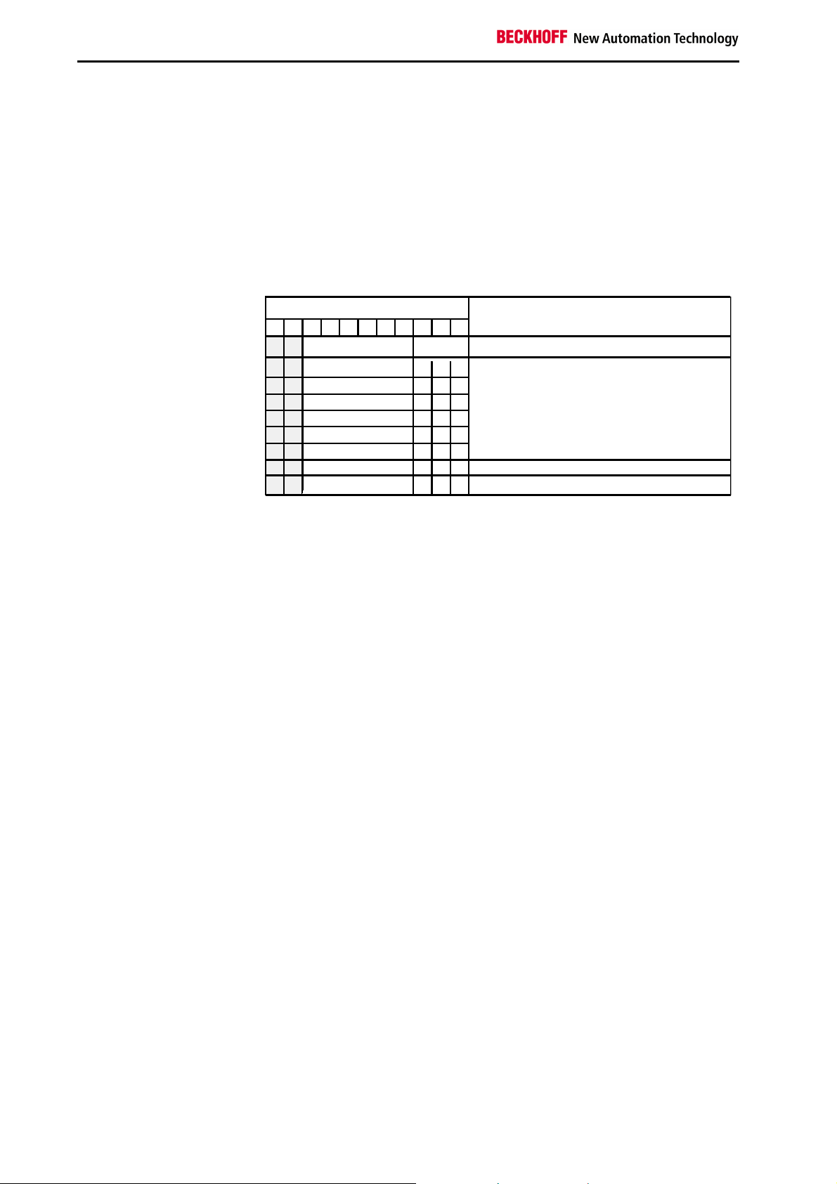
Set all the DIP switches to the desired configuration before you switch on
the Bus Coupler. Switches 7 and 8 are used to set the baud rate, as shown
in the following table.
Setting the DIP switches
Setting the baud rate
Setting the MAC ID
Switch on the Bus Coupler
Setting baud rates 1 2 3 4 5 6 7 8
125 kbaud
250 kbaud
500 kbaud
(Default) 125 kbaud
off off
on off
off on
on on
DIP switches 1 to 6 are used to set the MAC ID, where switch 1 is the
lowest value bit 20, and switch 6 the highest value bit 25. The bit is set
when the switch is ON.
You can select the MAC ID from the range 0 to 63.
When you have set all the DIP switches to the desired configuration you
can switch on the Bus Coupler. Any changes you make to the switches
while the system is in operation will have no effect until the next time it is
switched on.
22 BK52x0
Page 23
Power supply
C+
C-
00
X0
Beckhoff
CAN-L
Screen
Connector Pin assignment / DeviceNet
connection
DeviceNet connection
BK5200, BK5210:
Bus power and terminal
power are supplied
separately.
Both power supplies must
be connected.
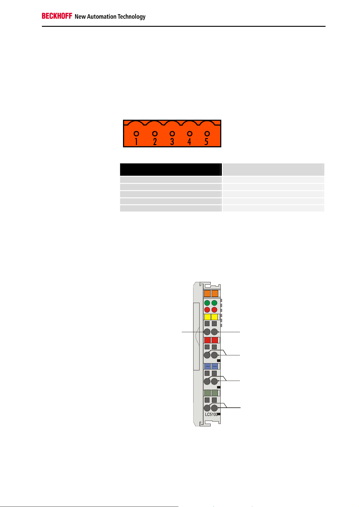
A 5-pin plug is supplied to connect the DeviceNet bus cable. When it is
plugged into the Bus Coupler, pin 1 is at the top. The figure shows the
socket in the Bus Coupler. The power supplied by this plug is isolated from
the power supply of the terminal to the right of the Bus Coupler. Both
power sources must be connected before the system can operate.
BK5200, BK5210, LC5200 DeviceNet
DeviceNet connection
LC5200
Connection diagram for the
LC5200 Bus Coupler
Pin assignment of DeviceNet
connection
1
2
3
4
5
V+
CAN-H
GND
CAN-L
V-
In the low cost LC5200 coupler, the CAN wires are connected directly to
the contact points 1 (CAN-H, marked with C+) and 5 (CAN-L, marked with
C-). V+ is placed on the terminal locations 2 and 6. V- is placed on the
terminal locations 3 and 7. The screen can optionally be connected to
contact points 4 or 8, which are connected to the top hat rail via an R-C
network.
0201
CAN-H
+ +
V+
V-
S S
.
BK52x0 23
Page 24

BK5200, BK5210, LC5200 DeviceNet
Byte 0
Byte n
Object from master to the Bus Coupler
Object from Bus Coupler to the master
Data string from the
DeviceNet master to the
Bus Coupler:
first byte-oriented data, and
then bit-oriented data.
4 bytes for 2-channel
analog output terminals
2 bits for 2-channel digital
output terminals
First the data from all the
analog outputs
Then the data for the digital
outputs is transmitted in
bytes
Some of the bits in the last
byte may be unused
Data exchange
Data is transferred between masters and slaves in the form of objects. The
Bus Coupler recognises two objects: an input object and an output object.
You can use the configuration software to map the input/output bytes onto
specific memory areas in the controller. The Bus Coupler uses a consistent
algorithm to correlate the object data to the peripherals. Various examples
of correlations between addresses and peripherals are explained in the
appendix. A (data) object which is transferred from the DeviceNet master
to the Bus Coupler must begin with the byte-oriented values, which is the
data for the analog output terminals. The bit-oriented data for digital
outputs may not be transmitted until all the byte-oriented values have been
sent.
Analog outputs receive 16 bits of data, i.e. two bytes, for each channel. An
analog output terminal with 2 channels must therefore receive 4 bytes. A
digital output terminal with 2 channels needs a total of 2 bits of data, one
for each channel.
The first 4 bytes of an object which is transferred to the terminal strip are
assigned to the first analog output terminal, which is the analog output
terminal nearest to the Bus Coupler. Other terminals which are located
between the Bus Coupler and the first analog output terminals are
disregarded. The next four bytes of the object go to the second analog
output terminal in the terminal strip. Any other terminals between the first
and second analog output terminals are disregarded.
When the last analog output terminal in the terminal strip has received its
data, the digital outputs are served. Data is always transferred in the form
of bytes, so the next byte from the data string contains data for 8 digital
outputs. Bit 0 and bit 1 are assigned to channels 1 and 2 of the first digital
output terminal after the Bus Coupler. Other types of terminal which are
located in between are ignored.
Bits 2 and 3 go to the 2 channels of the second digital output terminal, bits
4 and 5 to the third and bits 6 and 7 to the fourth. There may be other
terminals located between these digital output terminals, and if so they will
be disregarded.
Additional bytes are read from the data string until the last digital output in
the terminal strip has been dealt with. If the total number of digital outputs
is not a multiple of 8, there will be a number of bits left over in the last data
byte; these will be discarded.
24 BK52x0
Status byte
Byte n
. . . . . .
. . . . . .
Bit data
. . . . . .
Bit data
. . . . . .
. . . . . .
. . . . . .
. . . . . .
Byte data
. . . . . .
Byte data
Byte 0
Page 25

BK5200, BK5210, LC5200 DeviceNet
Object from the Bus
Coupler to the DeviceNet
master for transferring the
input data:
first byte-oriented data,
and then bit-oriented data.
Status byte at the end of
the object sent to the
master
Status byte=0: I/O RUN
Status byte=1: I/O ERR
LED "RUN"
LED "OVERFL"
LED "CONNECT"
LED "BUS OFF"
LED "I/O RUN"
LED "I/O ERR"
LED "I/O ERR"
The object sent by the Bus Coupler to the DeviceNet master also contains
the byte-oriented data at the beginning, followed by the bit-oriented data.
Transfers in this direction also include a status byte, which comes right at
the end of the object.
The byte-oriented data contains the values from the analog inputs and the
bit-oriented data the values from the digital inputs.
The first four bytes contain the data from the first analog input terminal in
the terminal strip, where each pair of bytes is the 16 bit value of one input.
The next four bytes correspond to the next analog input terminal and so on,
analogously to the procedure described above.
After the byte-oriented data from all the analog inputs come the values
from the digital inputs. Eight digital inputs are transferred in each byte. As
before, if the total number of digital inputs in the terminal strip is not a
multiple of 8, the last data byte will contain one or more superfluous bits.
An extra status byte is transferred at the end of each string sent by the Bus
Coupler to the DeviceNet master, and this returns the status of the terminal
strip. Its value corresponds to the status displayed on the I/O LEDs on the
Bus Coupler: while the terminal strip is functioning correctly, the LED ”I/O
RUN” will be lit and the status byte will contain the value 0; as soon as an
error occurs, the LED ”I/O ERR” will light up and the status byte will contain
the value 1.
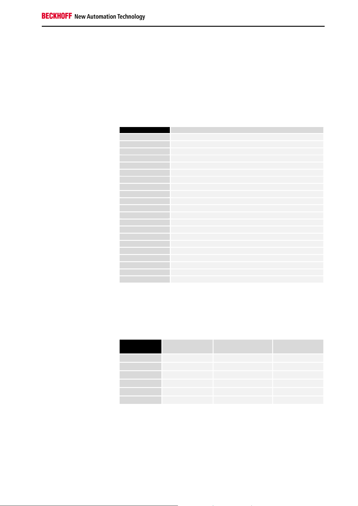
Light-emitting diodes
Module status LEDs ”MS”
The green LED flashes: Configuration is incorrect
The green LED is permanently lit: Status is OK.
The red LED flashes: Receive queue overflow
The red LED is permanently lit: Status is OK.
Network status LEDs ”NS”
The green LED flashes: Bus Coupler is ready for
communication, but not yet
assigned to the master.
The green LED is permanently lit: Bus Coupler is assigned to the
master, data is being exchanged.
The red LED flashes: Timeout on I/O connection
The red LED is permanently lit: BUS OFF: CAN error, devices
have identical node addresses.
Input/output status ”I/O”
The green LED is lit: The Bus Terminals are working
correctly.
The red LED is lit: I/O error, a Bus Terminal or an
internal K-Bus with a fault.
The red LED flashes: The Bus Terminals are being
configured
BK52x0 25
Page 26
BK5200, BK5210, LC5200 DeviceNet
Vendor ID
The vendor ID is # 108.
DeviceNet Group
The BK5200, BK5210 and LC5200 Bus Couplers are exclusively Group 2
devices.
IDENTIFIER BITS
9
10
1 0
1
1
1
1
1
1
1
1
78
0
0
0
0
0
0
Destination MAC ID Reserved for Predefined Master/Slave Connection Management
0
Destination MAC ID
0
Overview of the identifiers used
6
MAC ID
MAC ID
MAC ID
MAC ID
MAC ID
MAC ID
MAC ID
MESSAGE ID
4
5
3
Group 2
Message ID
0 0 0
0 0 1
0 1 0
0 1 1
1 0 0
1 0 1
1 1 0
1 1 1
1
Group 2 Messages
Group 2 Message Identifier
Duplicate MAC ID Check Message
0
2
MEANING
26 BK52x0
Page 27

0
White EIA 395A within wire/cable limits
Bus cable: length, assignment
The maximum length of cable which can be used depends on the selected
baud rate. The following lengths should be understood as the total length
of the main line plus any branch lines.
125 kbaud 500 m
250 kbaud 250 m
500 kbaud 100 m
Length of
Thin Cable
Used
(meters)
BK5200, BK5210, LC5200 DeviceNet
100
80
125k baud
60
40
20
500k
250k baud
baud
0 50 100 150 200 250 300 350 400 450 500
Length of Thick Cable Used (meters)
L
+ 5 x L
thick
L
+ 2.5 x L
thick
L
+ L
thick
where L
= 500 at 125Kbaud
thin
= 250 at 250Kbaud
thin
= 100 at 500Kbaud
thin
is the length of thick cable and Lthin
thick
is the length of thin cable.
Braid Shield
Data Insulation
Color: W hite
A L/M Y
Shield
Data Insulation
Color: B lue
Jacket
DC Power Insulation
Color: Bl ack
AL /MY
Shield
Drain W ire
DC Power Insulation
Color: Red
The cable consists of two shielded wire pairs. One pair carries out the
transmission. The second pair distributes the supply power.
BK52x0 27
V+
CAN_H
SHIELD
CAN_L
V-
Connector wiring information
Red P.M.S. #207C
Blue P.M.S. #297C
Black P.M.S. #426C
Page 28

BK5200, BK5210, LC5200 DeviceNet
Node/App
Network
Node
Electrical isolation
BK5200, BK5210
The Bus Coupler BK5200 have electrical isolation between the DeviceNet
bus cable and the communication electronics of the Bus Coupler.
24 Power supply
Local source
BK5200 Block diagram
Specific
uP / CAN
Local
Supply
LC5200:
drain/shield
signal
power
Isolation
barrier
Power
Supply
Transceiver
Power Tap
Optical
Isolators
Shield
no
function
5V Reg
MWP
V+
V-
Potential levels of the BK5200 and BK5210
The LC5200 does not provide electrical isolation from the fieldbus and
peripheral level. If the peripheral level nevertheless needs to have an
electrically isolated implementation, this can easily be achieved through the
use of isolating terminals (KL9xxx).
28 BK52x0
Page 29
Example: composition of a process image
Appendix
in the Bus Coupler
With this configuration, the
Bus Coupler sets up the
following assignment list
Area for byte-oriented data,
analog outputs
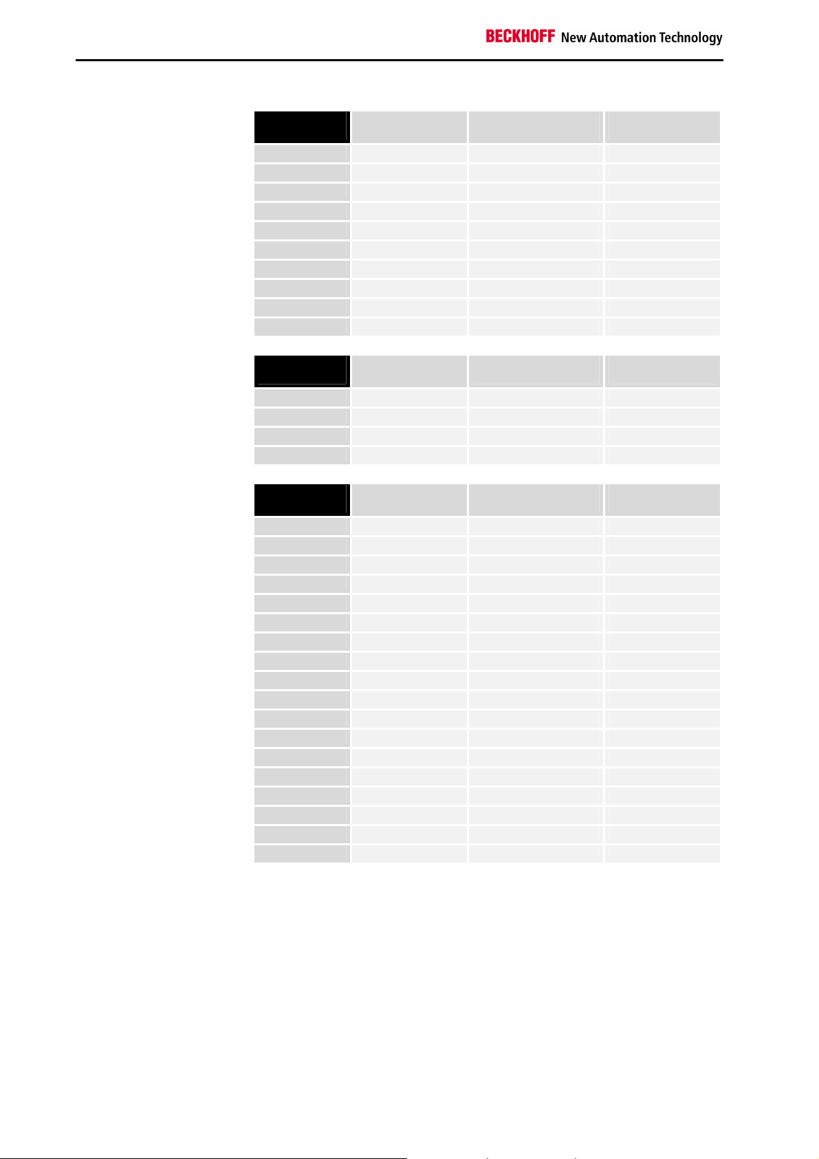
An example shows the assignment of in- and output channels to the
process image. The sample construction is to consist of the following
assembly of Bus Terminals:
Position Functional groups on the rail
POS01
POS02
POS03
POS04
POS05
POS06
POS07
POS08
POS09
POS10
POS11
POS12
POS13
POS14
POS15
POS16
POS17
POS18
POS19
POS20
POS21
By default, DeviceNet only supports signal channels that are 16 bits
wide. The STATUS/CONTROL BYTE is not available. This means, for
instance, that an analog input terminal with 2 channels appears with 2
x 16 bits in the process image. The images have corresponding
differences with respect to byte addresses and assignments.
Relative byte
address
0, 1
2, 3
4, 5
6, 7,
8, 9
10, 11
Bus Coupler
Digital inputs, 2 channels
Digital inputs, 2 channels
Digital inputs, 2 channels
Digital inputs, 2 channels
Digital inputs, 2 channels
Digital outputs, 2 channels
Digital outputs, 2 channels
Digital outputs, 2 channels
Analog inputs, 2 channels
Analog outputs, 2 channels
Analog outputs, 2 channels
Analog inputs, 2 channels
Power feed terminal
Digital inputs, 2 channels
Digital inputs, 2 channels
Digital inputs, 2 channels
Digital outputs, 2 channels
Digital outputs, 2 channels
Analog outputs, 2 channels
End terminal
Bit position Controller process
image
none O0, O1 POS11
none O2, O3 POS11
none O4, O5 POS12
none O6, O7 POS12
none O8, O9 POS20
none O10, O11 POS20
Position in the
block
Appendix
BK52x0 29
Page 30
Appendix
Area for bit-oriented data,
digital outputs
Relative byte
address
12
12
12
12
12
12
12
12
13
13
Area for byte-oriented data,
analog inputs
Relative byte
address
0, 1
2, 3
4,5
5,7
Area for bit-oriented data,
digital inputs
Relative byte
address
4
4
4
4
4
4
4
4
5
5
5
5
5
5
5
5
6
6
Positions POS14 and POS21 are not relevant to data exchange. They do
not appear in the list. If a byte is not fully utilised, e.g. E8, the Bus Coupler
pads the remaining bits of the byte with zeros.
Bit position Controller process
image
0 O12 POS07
1 O12 POS07
2 O12 POS08
3 O12 POS08
4 O12 POS09
5 O12 POS09
6 O12 POS18
7 O12 POS18
0 O13 POS19
1 O13 POS19
Bit position Controller process
image
none I0, I1 POS10
none I2, I3 POS10
none I4, I5 POS13
none I6, I7 POS13
Bit position Controller process
image
0 I4 POS01
1 I4 POS01
2 I4 POS02
3 I4 POS02
4 I4 POS03
5 I4 POS03
6 I4 POS04
7 I4 POS04
0 I5 POS05
1 I5 POS05
2 I5 POS06
3 I5 POS06
4 I5 POS15
5 I5 POS15
6 I5 POS16
7 I5 POS16
0 I6 POS17
1 I6 POS17
Position in the
block
Position in the
block
Position in the
block
30 BK52x0
Page 31

The distribution of the process image in the Bus Coupler in overview:
Output data in the Bus
Coupler
O0
...
byte-oriented data
...
A11
O12
bit-oriented data
O13
Input data in the Bus
Coupler
I0
...
byte-oriented data
...
E3
I4
...
bit-oriented data
...
I6
The base addresses I0 and O0 listed here are used as relative addresses
or addresses in the Bus Coupler. If you have an appropriate superordinate
DeviceNet system, you can use the bus master to enter these addresses at
any desired position in the controller's process image. You can use the
configuration software of the master to assign the bytes to the addresses in
the process image of the controller.
Appendix
BK52x0 31
Page 32

Support and Service
Support and Service
Beckhoff and their partners around the world offer comprehensive support and service, making available
fast and competent assistance with all questions related to Beckhoff products and system solutions.
Beckhoff's branch offices and representatives
Please contact your Beckhoff branch office or representative for local support and service on Beckhoff
products!
The addresses of Beckhoff's branch offices and representatives round the world can be found on her
internet pages: http://www.beckhoff.com
You will also find further documentation for Beckhoff components there.
Beckhoff Headquarters
Beckhoff Automation GmbH
Eiserstr. 5
33415 Verl
Germany
phone: + 49 (0) 5246/963-0
fax: + 49 (0) 5246/963-198
e-mail: info@beckhoff.com
web: www.beckhoff.com
Beckhoff Support
Support offers you comprehensive technical assistance, helping you no only with the application of
individual Beckhoff products, but also with other, wide-ranging services:
• support
• design, programming and commissioning of complex automation systems
• and extensive training program for Beckhoff system components
hotline: + 49 (0) 5246/963-157
fax: + 49 (0) 5246/963-9157
e-mail: support@beckhoff.com
Beckhoff Service
The Beckhoff Service Center supports you in all matters of after-sales service:
• on-site service
• repair service
•
spare parts servive
• hotline service
hotline: + 49 (0) 5246/963-460
fax: + 49 (0) 5246/963-479
e-mail: service@beckhoff.com
32 BK52x0
 Loading...