

Page 1

InterBus Coupler
BK4000
valid for all BK4xxx bus coupler
Technical Documentation
Version 1.3
2006-10-24
Page 2

Contents
Contents
1. Foreword 3
Notes on the documentation 3
Liability Conditions 3
Delivery conditions 3
Copyright 3
Safety Instructions 4
State at Delivery 4
Description of safety symbols 4
2. Basic information 5
The Beckhoff bus terminal system 5
The interfaces 7
Power supply 7
Power supply to the power contacts 7
Power contacts 7
Field bus connection 7
Configuration interface 8
K-bus contacts 8
Supply isolation 8
The operating modes of the bus coupler 9
Mechanical construction 10
Electrical data 12
The peripheral data in the process image 13
Starting operation and diagnostics 16
ID code and ID length 17
Run times and reaction times 19
3. InterBus coupler BK4000 in InterBus S 21
Presentation of the system 21
The medium: connector and cable 21
Configuration of masters 23
4. Annex 24
Example: combination of a process image in the bus coupler 24
Representation of analog signals in the process image 26
5. Support and Service 28
Beckhoff's branch offices and representatives 28
Beckhoff Headquarters 28
Beckhoff Support 28
Beckhoff Service 28
BK4000
Page 3

Foreword
Foreword
Notes on the documentation
This description is only intended for the use of trained specialists in control and automation engineering
who are familiar with the applicable national standards. It is essential that the following notes and explanations are followed when installing and commissioning these components.
Liability Conditions
The responsible staff must ensure that the application or use of the products described satisfy all the requirements for safety, including all the relevant laws, regulations, guidelines and standards.
The documentation has been prepared with care. The products described are, however, constantly under
development. For that reason the documentation is not in every case checked for consistency with performance data, standards or other characteristics. None of the statements of this manual represents a
guarantee (Garantie) in the meaning of § 443 BGB of the German Civil Code or a statement about the
contractually expected fitness for a particular purpose in the meaning of § 434 par. 1 sentence 1 BGB. In
the event that it contains technical or editorial errors, we retain the right to make alterations at any time
and without warning. No claims for the modification of products that have already been supplied may be
made on the basis of the data, diagrams and descriptions in this documentation.
Delivery conditions
In addition, the general delivery conditions of the company Beckhoff Automation GmbH apply.
Copyright
©
This documentation is copyrighted. Any reproduction or third party use of this publication, whether in
whole or in part, without the written permission of Beckhoff Automation GmbH, is forbidden.
BK4000 3
Page 4
Foreword
i
Safety Instructions
State at Delivery
All the components are supplied in particular hardware and software configurations appropriate for the
application. Modifications to hardware or software configurations other than those described in the documentation are not permitted, and nullify the liability of Beckhoff Automation GmbH.
Description of safety symbols
The following safety symbols are used in this documentation. They are intended to alert the reader to the
associated safety instructions..
This symbol is intended to highlight risks for the life or health of personnel.
Danger
This symbol is intended to highlight risks for equipment, materials or the environ-
Attention
ment.
This symbol indicates information that contributes to better understanding.
Note
4 BK4000
Page 5

Basic information
Up to 64 bus terminals
each with 2 I/O channels
for any form of signal
Decentralized wiring of
the I/O level
IPC as control unit
Bus couplers for all current
bus systems
Standard C rail assembly
Modularity
Display of channel status
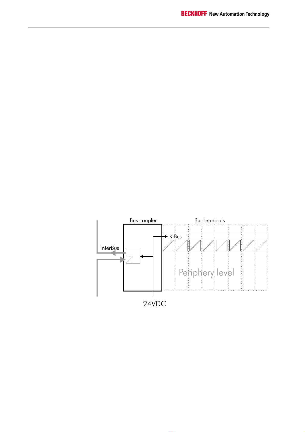
The K-bus
End terminal
The Beckhoff bus terminal system
The bus terminal system is the universal connecting link between a fieldbus system and the sensor/actor level. A unit consists of a bus coupler,
which is the interface to the fieldbus, and up to 64 electronic terminals, of
which the last is an end terminal. Terminals, each with two I/O channels,
are available for any form of technical signal and can be combined as desired. The various types of terminal are all constructed in the same way, so
that the planning costs are kept extremely low. The height and depth of the
construction are calculated for compact terminal cabinets.
Fieldbus technology makes it possible to use compact control architectures. The I/O level does not need to be taken right up to the control unit.
Sensors and actors can be connected decentrally with minimal lengths of
cable. You can position the control unit at any convenient location in the
installation. Using an industrial PC as control unit makes it possible to implement the operating and monitoring element as part of the control hardware, so the control unit can be located on an operating desk, control point
or similar. The bus terminals constitute the decentralized input/output level
of the control unit in the switch cabinet and its subordinate terminal cabinets. As well as the sensor/actor level, the power unit of the equipment is
also controlled via the bus system. The bus terminal replaces a conventional terminal as the cabling level in the switch cabinet; the switch cabinet
can be made smaller.
The Beckhoff bus terminal system combines the advantages of a bus system with the functionality of compact terminals. Bus terminals can be used
on all current bus systems and serve to reduce the diversity of parts in the
control unit, while behaving like the conventional standard units for the
relevant bus system and supporting the entire range of functionality of the
bus system.
The simple and compact assembly on a standard C rail, and the direct
cabling of actors and sensors without cross connections between the terminals, serve to standardize the installation, as does the uniformly designed labeling.
The small size and great flexibility of the bus terminal system mean that
you can use it anywhere that you could use a terminal and use any type of
connection – analog, digital, serial or direct sensors.
The modular construction of the terminal row, using bus terminals with
various functions, limits the number of unused channels to at most one per
function. Two channels to a terminal is the optimum solution for the number
of unused channels and the cost per channel. The possibility of using power input terminals to provide separate power supplies also helps to minimize the number of unused channels.
The integrated light-emitting diodes close to the sensor/actor indicate the
status of each channel.
The K-bus is the path taken by data within the terminal row. The bus coupler carries the K-bus through all the terminals by means of six contacts on
the side walls of the terminals, and the end terminal terminates the K-bus.
The user does not need to know anything about the function of the K-bus
or the internal operation of terminals and bus couplers. There are numerous software tools available which provide for convenient planning, configuration and operation.
Basic information
BK4000 5
Page 6
Basic information
End terminal
isolation
Potential
contacts
InterBus
Supply voltage
Power input terminals
for separately powered
groups
Three power contacts pass the operating power to the following terminals.
You can use power input terminals to subdivide the terminal row as desired
into groups, each with a separate power supply. These power input terminals are not taken into account for addressing the terminals, you can insert
them at any position along the terminal row.
You can install up to 64 terminals on a terminal row, including power input
terminals and the end terminal.
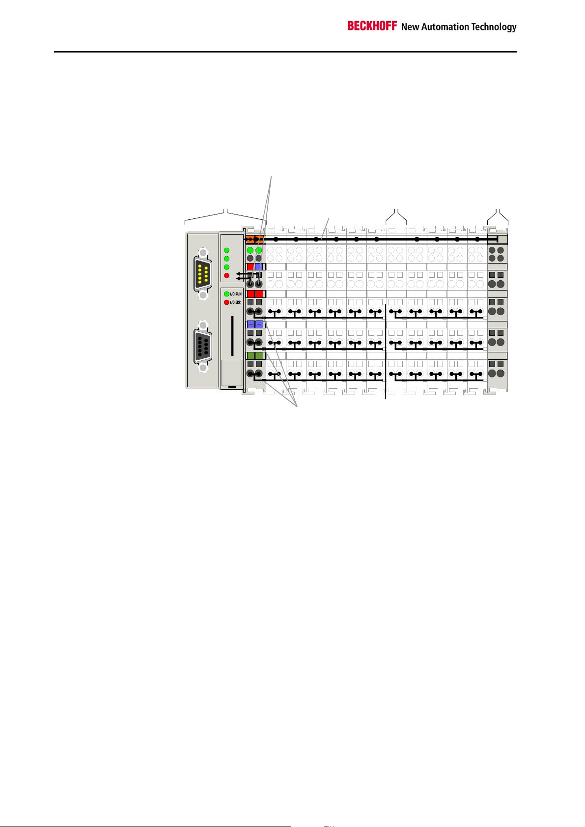
The principle of the bus
terminal
bus coupler
BK4000
for the
bus coupler
supply
terminal
K-bus
Bus couplers for various
fieldbus systems
rea dy
B A
RC
RD
BECKHOFF
0201
24V
0V
+ +
BK 4000
PE PE
Power
Electrical
INT ER BU S
You can use a variety of bus couplers to attach the electronic terminal row
quickly and easily to the various fieldbus systems, and you can also subsequently convert to a different fieldbus system. The bus coupler deals with
all the necessary monitoring and control tasks for operating the attached
bus terminals, indeed all the operation and configuration of the bus terminals is carried out via the bus coupler. The fieldbus, K-bus and I/O level are
electrically isolated.
If the exchange of data across the fieldbus is temporarily interrupted, logic
states are preserved, digital outputs are cleared and analog outputs revert
to a reset value which can be individually configured for each output when
the equipment is set up.
6 BK4000
Page 7
The InterBus-coupler
BK4000
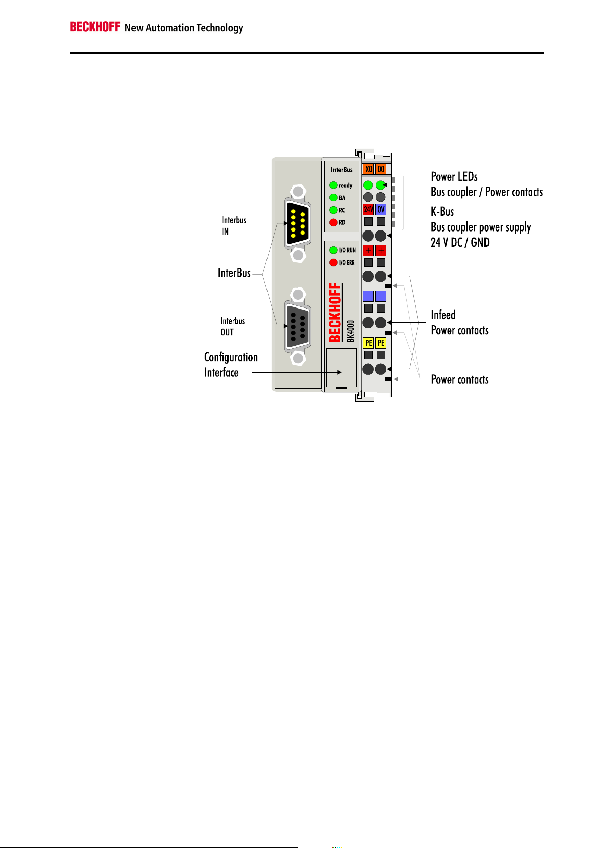
The interfaces
There are six ways of making a connection to a bus coupler. These interfaces are designed as plug connections and spring terminals.
Basic information
24 V DC on the topmost
terminals “24 V” and “0 V”
Lower 3 terminal pairs for
power input
maximum 24 V
maximum 10 A
Spring contacts at the side
9 pin Sub-D female
connector
9 pin Sub-D male connector
Power supply
The bus couplers need an operating power of 24 V DC which is connected
via the topmost spring terminals, labeled “24 V” and “0 V”. This power supply
serves not only the electronic components of the bus coupler but (via the Kbus) also the bus terminals. The power supply of the bus coupler circuitry
and that of the K-bus are electrically isolated from the voltage of the field
level.
Power supply to the power contacts
The six lower connections with spring terminals can be used to supply power
to the peripherals. The spring terminals are connected in pairs to the power
contacts. The power supply to the power contacts has no connection to the
power supply of the bus couplers. The power input is designed to permit
voltages up to 24 V. The pair-wise arrangement and the electrical connection
between the feed terminal contacts makes it possible to loop through the
wires connecting to different terminal points. The load on the power contact
may not continuously exceed 10 A. The current capacity between two spring
terminals is the same as the capacity of the connecting wires.
Power contacts
On the right-hand side face of the bus coupler are three spring contacts
which are the power connections. The spring contacts are recessed in slots
to prevent them from being touched. When a bus terminal is connected, the
blade contacts on the left-hand side of the bus terminal are connected to the
spring contacts. The slot and key guides at the top and bottom of the bus
couplers and bus terminals ensure reliable location of the power contacts.
Field bus connection
There is a recessed front surface on the left-hand side. The typical Interbus
connectors can be inserted here. You will find a detailed description of the
field bus interfaces in the Chapter entitled „The medium: connector and
cable“.
BK4000 7
Page 8
Basic information
Serial interface under the
front flap
Configuration interface
On the lower part of the front face you will find the standbus couplers which
are fitted with an RS232 interface. The miniature plug can be attached to a
PC by means of a connection cable and the configuration software KS2000.
This interface enables you to configure the analog channels. You can also
access the functionality of the configuration interface via the fieldbus by means of the PLC-Interface. The PLC interface consists of two additional bytes
that are also inserted in the process data.
6 contacts at the side
K-bus contacts
The connections between the bus coupler and the bus terminals are effected
by gold contacts at the right-hand side of the bus coupler. When the bus
terminals are plugged together, these gold contacts automatically complete
the connection to the bus terminals. The K-bus is responsible for the power
supply to the electronic components of the K-bus in the bus terminals, and
for the exchange of data between the bus coupler and the bus terminals.
Part of the data exchange takes place via a ring structure within the K-bus.
Disengaging the K-bus, for example by pulling on one the bus terminals, will
break this circuit so that data can no longer be exchanged. However, there
are mechanisms in place which enable the bus coupler to locate the interruption and report it.
3 supply groups:
fieldbus
K-bus
peripheral level
Supply isolation
The bus couplers operate with three independent supplies. The input power
supplies the electrically isolated K-bus circuitry in the bus coupler and the Kbus itself. The power supply is also used to generate the operating power for
the fieldbus.
Note: All the bus terminals are electrically isolated from the K-bus, so that the
K-bus is completely electrically isolated.
Setting up the power levels
in the bus terminal system
8 BK4000
Page 9
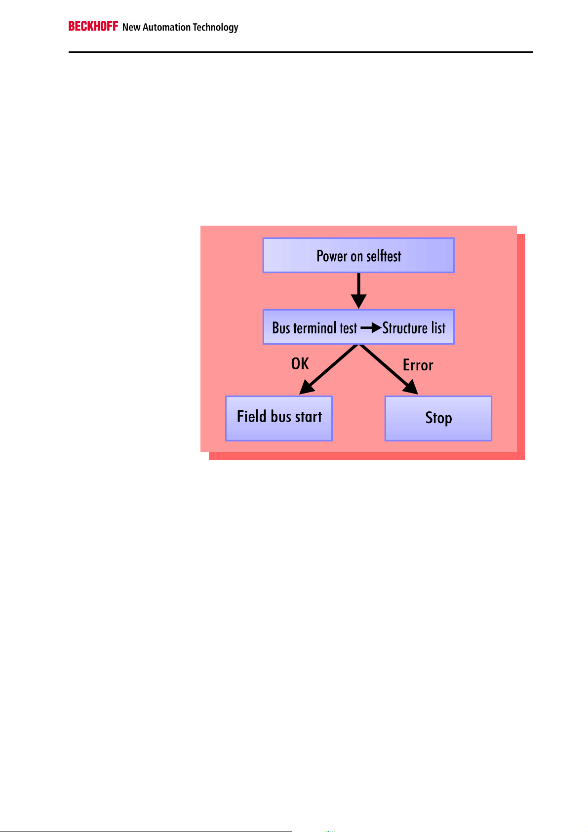
The operating modes of the bus coupler
When it is first switched on the bus coupler carries out a self-test to check
the functions of its components and the communications of the K-bus, and
while this is going on the red I/O LED will flash. When the self-test has
been completed successfully, the bus coupler will begin to test the attached bus terminals (the “bus terminal test”) and read in the configuration
from which it constructs an internal structure list, which is not accessible
from outside. If an error occurs the bus coupler will enter the operating
mode “STOP”. If the start-up sequence is completed without errors the bus
coupler will enter the mode “fieldbus start”. The I/O RUN LED is lightening.
Start-up behavior of the bus
coupler
Basic information
After troubleshooting, the bus coupler can only be brought to the normal
operating state by switching on again or by means of a field bus reset (triggered automatically by the master).
BK4000 9
Page 10

Basic information
Mechanical construction
The Beckhoff bus terminal system is distinguished by its small volume and
its high modularity. For project planning, one bus coupler and a number of
bus terminals must be planned. The bus coupler’s installation dimensions
are independent of the field bus system. The total height of the housings
may be exceeded if larger connectors are used, for example in the case of
some high bus connectors for the InterBus.
Dimensions of a bus
coupler
Assembly and connections
The overall width of the construction is the width of the bus coupler, including the bus end terminal, plus the width of the installed bus terminals. The
bus terminals are 12 mm or 24 mm wide, depending on their function. Depending on the gauge of cables used the overall height of 68 mm may be
overstepped by about 5 mm to 10 mm by the cables at the front.
It takes only a slight pressure to latch the bus coupler and the various bus
terminals onto a supporting 35 mm C rail and a locking mechanism then
prevents the individual housings from being removed. You can remove
them without effort if you first release the latching mechanism by pulling the
orange tab. You should carry out work on the bus terminals and the bus
coupler only while they are switched off: if you plug or unplug components
while the power is on you may briefly provoke some undefined state (and,
for instance, reset the bus coupler).
You can attach up to 64 bus terminals in series on the right-hand side of
the bus coupler. When you assemble the components, make sure that you
mount the housings so that each slot comes together with the corresponding key. You cannot make any functional connections merely by pushing
the housings together along the supporting track. When they are correctly
mounted there should be no appreciable gap between the adjacent housings.
The right-hand side of a bus coupler is mechanically similar to a bus terminal. There are eight connections on the top which can be used to connect
to thick-wire or thin-wire lines. The connection terminals are spring loaded.
You open a spring terminal by applying a slight pressure with a screwdriver
or other pointed tool in the opening above the terminal and you can then
insert the wire into the terminal without any obstruction. When you release
the pressure the terminal will automatically close and hold the wire secure-
10 BK4000
Page 11

Insulation test
PE power contacts
ly and permanently.
The connection between bus couplers and bus terminals is automatically
effected by latching the components together. The K-bus is responsible for
passing data and power to the electronic components of the bus terminals.
In the case of digital bus terminals, the field logic receives power via the
power contacts. Latching the components together has the effect that the
series of power contacts constitutes a continuous power track. Please refer
to the circuit diagrams of the bus terminals: some bus terminals do not loop
these power contacts through, or not completely (e.g. analog bus terminals
or 4-channel digital bus terminals). Each power input terminal interrupts the
series of power contacts and constitutes the beginning of a new track. The
bus coupler can also be used to supply power to the power contacts.
The power contact labeled “PE” can be used as protective earth or ground.
This contact stands proud for safety reasons and can carry short-circuit
currents of up to 125A. Note that in the interests of electromagnetic compatibility the PE contacts are capacitively connected to the supporting track.
This may lead to spurious results and even damage to the terminal when
you test the insulation (e.g. insulation test for breakdown using a 230V
mains supply to the PE line). You should therefore disconnect the PE line
on the bus coupler while you carry out insulation tests. You can disconnect
other power supply points for the duration of the test by drawing the power
supply terminals out from the remaining row of terminals by at least 10mm.
If you do this, there will be no need to disconnect the PE connections.
The protective earth power contact (“PE”) may not be used for any other
connections.
Basic information
BK4000 11
Page 12

Basic information
Electrical data
The InterBus couplers differ by virtue of their capacity levels. The electrical
data specific to the field bus is listed in this chapter. The following data
differs depending on whether a standard or an economy variant is meant
(BK4000, BK4500 and BK4010). Contrary to the standard variant, the economy variant limits the number of I/O points. Thus, there is no possibility of
connecting inputs and outputs other than digital inputs and outputs.
Technical data InterBus-coupler BK4000/BK4500 Economy -coupler BK4010
Power supply
Input current
K-Bus output current
Potential isolation
Number of bus terminals
Digital peripheral signals
Analog peripheral signals
Peripheral bytes
Configuration interface
Baud rates
Power contact voltage
Power contact current load
Dielectric strength
Typical weight
Operating temperature
Storage temperature
Relative humidity
Vibration / shock strength
EMC strength,. Burst / ESD
Installation position
Type of protection
24 V, - 15% + 20%
105 mA typ. ( 30 digital inputs- / 20 outputs ) 85 mA typ.
900 mA max. 300 mA max.
1750 mA max. 500 mA max.
500 Vrms (K-bus / power supply to periphery)
64 including potential feed terminals and end terminal
256 inputs and outputs 256 inputs and outputs
32 inputs and outputs#1 -64 input bytes and 64 output bytes 32 input and 32 output bytes
available for KS2000
500 KBaud in conformity with the standard
24V DC / AC
10 A
500 Vrms (Power contact / InterBus signal voltage), incoming interface
170g
0°C ... +55°C
-20°C ... +85°C
95%, no condensation
in conformity with IEC 68-2-6 / IEC 68-2-27
in conformity with EN 61000-4-4/ EN 61000-4, limit EN 50082-2-4
any
IP20
Current consumption on the
K-Bus
For operation of the K-Bus electronics, the bus terminals require power
from the K-Bus which the bus coupler supplies. Refer to the catalog or the
corresponding data sheets of the bus terminals for details of the current
consumption of the K-Bus. At the same time, pay attention to the maximum
output current of the bus coupler that is available for powering the bus terminals. By means of a special power supply terminal, an infeed into the KBus is possible at any point. Please consult Beckhhoff’s technical support
for details of how to use a power supply terminal.
12 BK4000
Page 13

The peripheral data in the process image
Basic information
After power on, the bus coupler determines the configuration of the inserted input/output terminals. The bus coupler automatically assigns the affiliations between the physical slots of the input/output channels and the
addresses of the process image.
The bus coupler generates an internal allocation list in which the input/output channels have a specific position in the process image. Here, a
distinction is made according to inputs and outputs and according to bitoriented (digital) and byte-oriented (analog or complex) signal processing.
Two groups with only inputs or outputs each are formed. In one group, the
byte-oriented channels are at the least significant address in ascending
order. This block is followed by the bit-oriented channels.
Digital signals
(bit-oriented)
Digital signals are bit-oriented. This means that one bit of the process
image is assigned to each digital channel. The bus coupler sets up a block
of memory containing the current input bits and arranges to immediately
write out the bits from a second block of memory which belongs to the output channels.
The precise assignment of the input and output channels to the process
image of the control unit is explained in detail in the Appendix by means of
an example.
Analog signals
(byte-oriented)
Processing of the analog signals is fundamentally byte-oriented. The analog input and output values are stored in the memory in a two-byte notation. The values are represented as "SIGNED INTEGER". The numeric value "0" stands for the input/output value "0V",0mA" or "4mA". In the default
setting, the maximum value of the input/output value is represented by
"7FFF" hex. The intermediate values are accordingly proportional with respect to one another. The area with a resolution of 15 bits is not realized
with every input or output stage. In the event of an actual resolution of 12
bits, the last three bits are of no effect for outputs and, for inputs, they are
read as "0". Each channel also has a control and status byte. The control
and status byte is the most significant byte in the most significant word. An
analog channel is represented with four bytes in the process image, three
bytes of which are used. (In the BK3000 and BK4000, only two bytes are
occupied for each analog channel in the process image of the corresponding bus system. The control and status bytes of the bus terminals can
also be inserted by reconfiguration in the bus coupler and in the bus terminals.)
Special signals and
interface
The BK4000 supports bus terminals with further interfaces such as RS232,
RS485, incremental encoders or others. These signals can be controlled
just like the above-mentioned analog signals. To some extent, a bit width of
16 does not suffice for the special signals. The bus coupler is capable of
supporting any byte width. The effective byte length of the bus terminals
can be preset with the KS2000 software.
Default assignment of
inputs and outputs to the
process image
When the bus coupler is first switched on it determines the number of attached bus terminals and sets up a list of assignments. This list distinguishes
between analog channels and digital channels and between input and output; which are grouped separately. The assignments begin immediately to
the left of the bus coupler. The software in the bus coupler creates the
assignment list by collecting the entries for the individual channels one at a
time, counting from left to right.
BK4000 13
Page 14

Basic information
bus terminals. The byte length of these terminals can be adjusted with the
These assignments distinguish four groups:
Function type of the channel Assignment level
1.
2.
3.
4
Analog outputs byte-wise assignment
Digital outputs bit-wise assignment
Analog inputs byte-wise assignment
Digital inputs bit-wise assignment
Analog inputs/outputs are representative of other complex multi-byte signal
KS2000 software.
Overview of the breakdown of the process image in the bus coupler:
The „x“ variable represents the number of analog channels. By default, one
channel has one word with 16 bits. The „y“ variable represents the number
of words with digital data. It is calculated on the basis of:
y = ( integral result (number of digital channels / 16) + 1 )
Output data in the
bus coupler
A0
...
byte-oriented data
...
Ax
Ax+1
bit-oriented data
Ax+y
Input data in the
bus coupler
E0
...
byte-oriented data
...
Ex
Ex+1
...
bit-oriented data
...
Ex+y
The path from the I/Os to
the process image in the
InterBus
The bus coupler automatically assigns the I/Os of the terminals to the process image in the Interbus protocol. The figure symbolically shows an allocation list. In special applications, the allocation list can be modified to suit
requirements by using the KS2000 configuration software.
The allocation list in the master has the same effect. Byte-by-byte allocation is possible with the Phoenix Contact Firmware version 4.0 and higher.
The master software CMD version 4.0 and higher is needed for this purpose. Setting via FB in the PLC is possible, but is not advisable owing to its
great complexity.
14 BK4000
Page 15

Data consistency
Data is described as being consistent if its contents fit together. The following contents belong together:
1. the high and low bytes of an analog value (word consistency).
2. The control/status byte and the affiliated parameter word for access to
the registers (e.g. 3-byte input/output for an analog channel).
In the interplay of the peripherals and the controller, data consistency is
fundamentally initially only ensured for one byte (for most IBS masters,
consistency exists for one word). That is to say, the bits of one byte are
read in together or are ouput together. The InterBus transports all data of
all inputs and outputs in one cycle. After an error-free transfer, the data is
available for the controller. In practical terms, the master realises the „making available“ by switching over from the old data block to the one that is
now the current one. If the controller accesses the data area at the time of
changeover, it reads a portion of the old data and a portion of the new data. As the controllers only access the memory word by word or even only
byte by byte, the corresponding data consistency is produced. For processing of digital signals, byte consistency is sufficient. In cases when values
with a length of more than 8 bits are transferred, e.g. in the case of analog
values, the consistency must be extended. Attention must be paid to the
correct method of acceptance by the controller of the consistent data from
the bus system’s master. Refer to the corresponding operating manual of
the master system for a detailed description of the correct procedure.
Complex signal processing
All byte-oriented signal channels such as RS232, RS485 or incremental
encoders partly operate with byte lengths of more than two bytes. With the
exception of the length difference, handling of these is always comparable
to that of analog signals.
Calculating the effective
length
The greater number of inputs or outputs defines the effective length in the
InterBus system. If the number of inputs and outputs does not correspond,
remaining words are inserted in the process image as „blank words“. These words are read with the contents „0000hex“ and writing to these
addresses has no effect (but the data is transferred and is stored in the bus
coupler’s memory).
Basic information
BK4000 15
Page 16

Basic information
Starting operation and diagnostics
After power-on, the bus coupler immediately checks the connected configuration. Error-free startup is signalled by extinguishing of the red „I/O ERR
„ LED. Flashing of the „I/O ERR“ LED indicates an error in the area of the
terminals. The error code can be determined by the frequency and quantity
of flashing. This enables swift troubleshooting.
The diagnostic LEDs
The bus coupler has two groups of LEDs to provide a status indication. The
top group with four LEDs indicates the status of the respective InterBus
system. The meanings of the „Field bus status LEDs“ are explained in the
corresponding chapters of this manual. These correspond to the usual field
bus displays.
There are two further green LEDs on the top right hand side of the bus
coupler to indicate the supply voltage. The left LED indicates the 24V power supply of the bus coupler. The right LED signals the supply to the Power contacts.
Local errors
Two LEDs, the „I/O-LEDs“, in the area under the aforementioned field bus
status LEDs, serve to indicate the operating states of the bus terminals and
connection to these bus terminals. The green LED lights up to indicate
error-free operation. Error-free means that communication with the field
bus system is also running without errors. To indicate errors, the red LED
flashes at two different frequencies. Errors are coded in the flashing code
as follows:
Flashing code
fast flashing
first slow sequence
second slow sequence
Errors
Error code Error argument Description
1 pulse
2 pulses
3 pulses
4 pulses
5 pulses
6 pulses
Error location
The number of pulses in the error segment indicates the position of the last
bus terminal before the error. Passive bus terminals such as a supply terminal without diagnostics are not counted.
The bus coupler does not end the flashing sequence when the error is
remedied. The bus coupler’s operating state is still „Stop“. The bus coupler
can only be restarted by switching off and switching on the supply voltage.
It is only permitted to remove and instert bus terminals from the network in
the deactivated state. The electronic circuitry of the bus terminals and of
the bus coupler is largely protected against destruction, but malfunctions
and damage cannot be ruled out when they are plugged together under
voltage.
Start of the error code
Error code
Error argument
0
1
2
0
n (n > 0)
0 Terminal bus command error
0
n
n Terminal bus error during register communica-
0
n (n > 0)
EEPROM checks on error
Inline code buffer overflow
Unknown data type
Programmed configuration
Invalid table entry / bus coupler
Table comparison (terminal n) invalid
Terminal bus data error
Breakage after terminal n (0: coupler)
tion with terminal n
More than 32 words data width fitted on the bus
coupler
16 BK4000
Page 17

Field bus error
Default setting
Observe modification by
KS2000
The top four LEDs indicate the operating states of InterBus communication.
The bottom two LEDs indicate local communication between the bus coupler and bus terminals (as explained above).
However, there is a relationship between the bottom green I/O RUN-LED
and the field bus when the bus coupler is switched to the „SYNCHRONOUS“ mode. Then the I/O RUN-LED only lights up in connection with
access on the internal K-Bus. That is to say, the green I/O RUN-LED does
not light up until data exchange via the field bus is commenced. This means that the field bus must access the bus coupler. This relationship does
not apply in the bus coupler’s default setting (FREERUN). In this state, the
I/O RUN - LED is independent of the InterBus status.
Basic information
The fieldbus status LEDs indicate the operating states of the field bus. The
functions of the InterBus system are indicated by the „ready“, „BA“, „RC“
and „RD“ LEDs.
The meanings of the LEDs on the BK4000
ready BA RC RD Meaning Remedy
lit off off off The bus coupler is ready
lit lit lit off Remote bus active
lit off lit off Incoming field bus connection has
lit lit off lit Continuing remote bus is off, owing
off off off off No function, power failure
Data transfer with Master running
been established,
no connection
to a cable fault or deactivated by the
Master
Search for a cable discontinuity or a short-circuit of the
master.
The green I/O LED lights up in connection with access to the internal KBus. However, the bus coupler interrogates the configuration of the bus
terminals after power on and does not perform a data exchange with the
terminals. That is to say, the red I/O LED goes off after an error-free start
up without the green I/O LED having to light up. The green I/O LED does
not light up until data exchange is begun (see above).
ID code and ID length
ID code and ID length
Structure of the InterBus ID
code
In the ID cycle, which is run through to initialise the InterBus system, the
connected stations inform each other of their functions and their byte
lengths. After switching on, the InterBus coupler determines its length in
the InterBus during the initialisation phases of the bus terminals and generates a corresponding ID code. The InterBus coupler reports as a digital or
analog „external coupler“ of variable length. The length results from the
nature and number of fitted bus terminals.
The InterBus ID code consists of 2 bytes. The MSB describes the length of
the data words that are transferred. Bits 13, 14 and 15 can transfer messages. The LSB describes the type of the bus station in relation to the signal
type and other features such as remote bus / peripheral bus station, PPC,
ENCOM or DRIVECOM. The InterBus coupler BK4000 uses six IDs for
inputs / outputs, inputs and outputs (x1hex, x2hex, x3hex). The IDs are
BK4000 17
Page 18

Basic information
6543210
Data direction I/O, I,O
bit
used depending on the type of the bus terminals, i.e. analog or digital
(3xhex, 0xhex). These are the identifiers for remote bus stations from thirdparty manufacturers.
If there are analog and digital terminals on one BK4000, the bus coupler
uses the analog identifier 3xhex. The following table shows an overview.
Signal type Signal direction HEX-Value
Digital
Digital
Digital
Analog
Analog
Analog
The length information is coded automatically from 0 to 32 words. A standard length of up to 9 words is supported by every bus master. The length
up to 32 words is only supported from firmware version 3.2 and higher.
Please pay attention to lengths greater than 10 words.
15 14 13 12 11 10 9 8 7
INPUTS 02
OUTPUTS 01
INPUTS/OUTPUTS 03
INPUTS 32
OUTPUTS 31
INPUTS/OUTPUTS 33
Participant-Type
Participant-Class
Data width
Messages
Depending on the configuration software for the InterBus master interfaces,
the length and the ID code are entered separately or as a value in „16hex format“.
Most configuration programs permit reading of the actual configuratioan by
the master. The following table shows the possibilities of the length code.
Length of fitted periphery Register width in the ID code
0
1 Word
2 Words
3 Words
4 Words
5 Words
6 Words
7 Words
8 Words
9 Words
10 Words
11 - 12 Words
13 - 14 Words
15 - 16 Words
17 - 24 Words
25 - 32 Words
0
1 Word
2 Words
3 Words
4 Words
5 Words
6 Words 1)
7 Words 1)
8 Words
9 Words
10 Words 1)
12 Words 1)
14 Words 1)
16 Words 1)
24 Words 1)
32 Words 1)
18 BK4000
Page 19

1) The data widths are only supported from Firmware version 3.20 and
higher by the interfaces of the PLC and from driver version 2.0 by the PC
card.
Remark:
In InterBus master interfaces with firmware versions less than 4.0, the peripheral data block of a bus coupler can only be placed in the process
image as a coherent block with one base address. All following data of the
block is assigned to the subsequent addresses.
Register expansion
The differing length of the bus coupler is realised by a rigister expansion.
The number of additional registers is switched by the internal micro processor. The length is determined after power-on or after a reset and is
written into a register expansion module as a numeric value. A change in
the length is not possible without interrupting the exchange of data on the
InterBus. The BK4000 must be restarted by means of a reset. The master
must be reconfigured to the new length. In the auto configuration mode of
some InterBus masters, the master starts even after the length of individual
slaves has been modified if this does not result in any overlapping of
addresses.
Run times and reaction times
Controller / master
Transfer of the signals from the input into the controller and from the controller to the outputs requires a run time. This is composed of various portions, i.e. transfer from the controller to the master; transfer via the InterBus
and transfer from the bus coupler to the outputs. It applies conversly in the
return direction.
Refer to the master manufacturer’s data for details of the reaction time
from the controller to the Master. The newly transferred data does not acquire validity until one cycle has been transferred completely.
The reaction time TIBS on the InterBus is composed of the following. The
constants SW, M, N and TBIT constitute the sum of the cycle time in ms. In
the worst case, the reaction time is 2 x cycle time because the data does
not acquire validity until after the end of the cycle.
TIBS = ( SW + (13 * ( 6 + N ) + 1,5 * M ) x TBIT ) * 2
SW = 0.2 ms
M = Number of bus couplers
N = Number of effective byte lengths
TBIT = 0.002 ms
Pay attention to the number of bytes and not the word length in the calculation of the times.
Note:
Pay attention to particular delays in the event of transmission errors.The
InterBus requires 5 cycle times until the next valid data can be exchanged.
Basic information
BK4000 19
Page 20

Basic information
K-Bus reaction time
The reaction time on the K-Bus is determined by shifting / reading and
saving of the data. The following table contains measured values for typical
setups. It is possible to extrapolate to larger figures.
Terminals fitted on the bus coupler Run time on the K-Bus
Digital
OUT
4 0 0 150
8 0 0 170
12 0 0 170
16 0 0 200
20 0 0 200
24 0 0 220
28 0 0 220
32 0 0 245
0 4 0 150
0 8 0 180
0 12 0 180
0 16 0 200
0 20 0 200
0 24 0 230
0 28 0 230
0 32 0 250
4 4 0 170
8 8 0 195
12 12 0 220
16 16 0 250
20 20 0 275
24 24 0 300
28 28 0 325
32 32 0 350
4 4 1 (KL3202) 630
4 4 2 (KL3202) 700
Digital
IN
Analog
IN/OUT
T_cycle
(us)
20 BK4000
Page 21

InterBus coupler BK4000 in InterBus S
InterBus coupler BK4000 in InterBus S
System ccnfigurations and
device types
Remote bus connection
Assignments on the
connector and coupling of
the remote bus cable
Presentation of the system
The InterBus system is structured as a data ring based on a central master/slave access method. It has the structure of a spacially distributed shift
register. With its registers of differing length, each unit is part of this shift
register ring, through which the master shifts the data serially.
Use of the ring structure offers the possibility of synchronous sending and
receiving of data. The two data directions of the ring are accommodated in
one cable.
Each station in the InterBus system has an ID register (identification register). This register contains information about the module type, the number
of input and output registers and status and error states.
The InterBus system basically has two operating modes:
-
The ID cycle, which is run through to initialise the InterBus system and
whenever requested. In the ID cycle, the interface module reads the ID
registers out of all devices on the bus system and builds up the process image on the basis of this information.
-
The data cycle, the actual work cycle, which handles data transfer. In
the data cycle, the input data from all devices is transferred out of the
registers into the interface module and output data is transferred from
the interface module to the devices.
The InterBus Club carries a large number of different ID codes. Except for
6 ID codes, these ID codes are used up for couplers of digital and analog
peripherals from Phoenix Contact. Therefore, manufacturer identification
via the ID code is not possible. (Refer to the chapter entitled „ID code and
ID length“ for detailed explanations). Handling of the InterBus BK4000
does not differ from the units from other manufacturers.
The medium: connector and cable
The InterBus distinguishes between the remote bus, the peripheral bus and
the installation remote bus. The InterBus coupler is equipped with the remote bus interface. The Interbus coupler has an incoming and outgoing
interface on the basis of a D-SUB connector and coupling.
Outgoing remote bus,
9-pole D-SUB connector
/DO 6
DO 1
/DI 7
DI 2
COM 3
5
9
Cable Incoming remote bus,
9-pole D-SUB coupling
green
yellow
pink
grey
brown
Jumper
Jumper
6 /DO
1 DO
7 /DI
2 DI
3 COM
BK4000 21
Page 22

InterBus coupler BK4000 in InterBus S
PE
PE
(1, 6) DO, DO-N
(2, 7) DI, DI-N
Incoming
Outgoing
BK4500 InterBus Coupler
and fibre optic connection
Fibre optic conductor: the InterBus Club elaborated the specification of a
transmission technology based on fibre optic conductors for applications in
highly interference-prone environments and also to increase the range. For
the Beckhoff InterBus bus coupler with fibre optic connection (BK4500) use
is made of F-SMA connectors and, in this case, the length between two
stations is 1-40 m. Attention must be paid to ensuring that the slide switch
for activating and deactivating the continuing interface is set to the corresponding position. If the BK4500 is the last InterBus station in the ring,
the switch must be set to the OFF/END position. It must be set to the
ON/NEXT position if the BK4500 is in a position in the ring.
BK4500
RS-422 transfer in
accordance with the
InterBus standard
Wiring for InterBus
Fundamental
characteristics
Network topology
Medium
Number of modules
between two stations
Total length
Data transfer rate
Connector
Interface
Ring with integrated return line
Shielded twisted-pair cable, 3x twisted-pair with shield
256
400 m
12.8 km
500 Kbits/s
9-Pin D-Sub plug connector and 9-pin D-Sub socket
Interface
DO, DO-N (1,6)
COM (3)
(3) COM
DI, DI-N (2,7)
(5,9)
Shield
In systems with more than two modules, all modules are wired in succession. The ends of the bus cable must be terminated with resistors, which are
located in each module. A jumper in the connector of the continuing interface signals to the bus coupler that a further modules follows.
To be able to realise uninterrupted operation, none of the connectors must
be withdrawn and all modules in the ring must be operable.
22 BK4000
Page 23

Configuration of masters
As already explained above, the InterBus coupler creates a data area with
input and output bytes. The affiliations between channels of the bus terminal and the bits and bytes of the process image are set by the bus coupler.
The InterBus master exchanges a coherent input and output data block
with each InterBus coupler. The affiliations of the bytes from this data block
to the addresses of the process image are established via data blocks of
the PLC or the IBS SYS SWT or IBS CMD SWT G3 and G4 configuraton
software from Phoenix Contact. For other masters, use the manufacturer’s
corresponding tools.
Master configuration
software
Master / software Configuration software Manufacturer
PLC-Interfaces
versions < 4
PC interface
version < 4
PLC-interfaces
versions >4
PC interfaces
versions >4
Ensuring data consistency
Consistency of a station’s data is ensured by the data transfer protocol of
the InterBus. Consistency throughout the entire process image is ensured
by sychronous sampling.
Asynchronous access by the controller’s CPU ( mostly PLC) to the data
area of the InterBus master may lead to inconsistencies. Most InterBus
masters ensure access to 16-bit words and, to some extent, also to 32-bit
double words. Please refer to the corresponding manufacturer’s manuals
for further details of special access methods relating to the master interfaces.
The S5 modules IBS S5 DCB and IBS S5 DSC as InterBus masters are
common PLC interfaces.
The masters featuring firmware version 4.0 are particularly convenient to
operate. The CMD configuration software allows users to define the settings under Windows. Byte-by-byte and also bit-by-bit allocation of the peripheral data in the controller’s address area is possible. Data consistencies can be selected in groups.
Conformity with the
InterBus standard
The BK4xxx operate with the SUPI 3 (Serial Universal Peripheral Interface)
protocol chip. The SUPI 3 protocol chip handles the complete InterBus
protocol. In comparison with the predecessor versions (SUPI 2), the SUPI
3 offers extended diagnostic and error management. Please refer to the
manuals of the Interbus masters used for details of the supported functionalities of the SUPI 3 chips.
InterBus coupler BK4000 in InterBus S
IBS SYS SWT
IBS CMD SWT G3
IBS SYS SWT
IBS CMD SWT G3
IBS CMD SWT G4 Phoenix Contact
IBS CMD SWT G4 Phoenix Contact
Phoenix Contact
Phoenix Contact
BK4000 23
Page 24

Annex
Example: combination of a process image
Annex
In this configuration, the
bus coupler creates the
allocation list that
follows below
Part for byte-oriented data,
analog outputs
in the bus coupler
An example explains the affiliations of the input and output channels to the
process image. Our example setup should consist of the following bus
terminal modules:
Position Function module on the busbar
POS00
POS01
POS02
POS03
POS04
POS05
POS06
POS07
POS08
POS09
POS10
POS11
POS12
POS13
POS14
POS15
POS16
POS17
POS18
POS19
POS20
POS21
By default, InterBus, DeviceNet and Profibus couplers only map signal
channels of 16-bits width. The CONTROL/STATUS BYTE is not available.
That is to say, an analog input terminal with 2 channels, for example, appears in the process image with 2 x 16 bits. The figures showing the byte
addresses and the affiliations differ correspondingly when CONTROL/STATUS is activated.
relative
byte address
0, 1
2, 3
4, 5
6, 7,
8, 9
10, 11
Bus coupler
Digital inputs, 2 channels
Digital inputs, 2 channels
Digital inputs, 2 channels
Digital inputs, 2 channels
Digital inputs, 2 channels
Digital inputs, 2 channels
Digital outputs, 2 channels
Digital outputs, 2 channels
Digital outputs, 2 channels
Analog inputs, 2 channels
Analog outputs, 2 channels
Analog outputs, 2 channels
Analog inputs, 2 channels
Infeed terminal
Digital inputs, 2 channels
Digital inputs, 2 channels
Digital inputs, 2 channels
Digital outputs, 2 channels
Digital outputs, 2 channels
Analog outputs, 2 channels
End terminal
Bit position Process image in
the controller
none A0, A1 POS11
none A2, A3 POS11
none A4, A5 POS12
none A6, A7 POS12
none A8, A9 POS20
none A10, A11 POS20
Position in the
block
24 BK4000
Page 25

Part for bit-oriented, data,
digital outputs
relative byte
address
12
12
12
12
12
12
12
12
13
13
Part for byte-oriented data,
analog inputs
relative byte
address
0, 1
2, 3
4, 5
6, 7
Part for bit-oriented data,
digital input
relative byte
address
8
8
8
8
8
8
8
8
9
9
9
9
9
9
9
9
10
10
Positions POS14 and POS21 are not relevant with regard to data transfer.
They do not appear in the list. If a byte is not used completely, e.g. E8, the
bus coupler pads the remaining bits of the byte with zeros.
Bit position Process image in
the controller
0 A12 POS07
1 A12 POS07
2 A12 POS08
3 A12 POS08
4 A12 POS09
5 A12 POS09
6 A12 POS18
7 A12 POS18
0 A13 POS19
1 A13 POS19
Bit position Process image in
the controller
none E0, E1 POS10
none E2, E3 POS10
none E4, E5 POS13
none E6, E7 POS13
Bit position Process impage
in the controller
0 E8 POS01
1 E8 POS01
2 E8 POS02
3 E8 POS02
4 E8 POS03
5 E8 POS03
6 E8 POS04
7 E8 POS04
0 E9 POS05
1 E9 POS05
2 E9 POS06
3 E9 POS06
4 E9 POS15
5 E9 POS15
6 E9 POS16
7 E9 POS16
0 E10 POS17
1 E10 POS17
Position in the
block
Position in the
block
Position in the
block
Annex
BK4000 25
Page 26

Annex
Representation of analog signals in the
Output data in the
bus coupler
Input data in the
bus coupler
E8
Overview of the process image breakdown in the bus coupler:
A0
...
byte oriented data
...
A11
A12
bit oriented data
A13
E0
...
byte oriented data
...
E7
...
bit oriented data
...
E10
The base addresses E0 and A0 listed here apply as relative addresses or
addresses in the bus coupler. In the bus master software, a base peripheral address may be assigned to the base address of the bus coupler. All
following addresses are automatically assigned the successive addresses
depending on the length of the actual data words.
Firmware version 4.0 and higher of the InterBus interfaces:
The bus master may place the addresses in a freely chosen location in the
controller’s process image. The masters’s configuration software enables
any chosen assignment of the bytes to the addresses of the process image
in the controller.
process image
Each analog channel consists of three input bytes and three output bytes.
In the standard case, however, an analog channel only requires one data
word in the process image. These two bytes represent the value as a
signed integer, i.e. 15 bits with sign. The data format is used regardless of
the actual resolution. For example: in the case of a resolution of 12 bits, the
four least significant bits are of no relevance. By means of the KS2000
configuration software, the third byte can be inserted in the process image
for any channels. The least significant byte has control and status functons.
Various operating modes can be set with the control byte. The six least
significant bits can be used as addressing bits. Addressing serves to read
and write a register set. The register set has 64 registers and allows setting
of different operating parameters, for example selection of a thermocouple
type or representation of a value in a different numerica format.
26 BK4000
Page 27

I/O bytes of an
analog channel
in the process image
Output byte 1 Output byte 0 Control byte
Input byte 1 Input byte 0 Status byte
Significance of the
control/status byte
for access to the
register model
BIT 7 0 = NORMALMODE, 1 = CONTROL MODE
BIT 6
BIT 5
BIT 4
BIT 3
BIT 2
BIT 1
BIT 0
0 = READ, 1 = WRITE
Register address, MSB
Register address
Register address
Register address
Register address
Register address, LSB
Register set of an
analog channel
63
47
31
15
User area
16 0
OFF SET
GA IN
0 Length Typ
This representation is not accessible in the bus coupler’s default. The
KS2000 software is needed.
The meanings of the registers and of the status bytes are explained in the
bus terminal’s corresponding data sheets. As far as its structure is concerned, the module is identical for all bus terminals that enable more extensive signal processing.
Annex
Manufacturer settings
Software Vers.
Type
Auxiliary process image
BK4000 27
Page 28

Support and Service
Support and Service
Beckhoff and their partners around the world offer comprehensive support and service, making available
fast and competent assistance with all questions related to Beckhoff products and system solutions.
Beckhoff's branch offices and representatives
Please contact your Beckhoff branch office or representative for local support and service on Beckhoff
products!
The addresses of Beckhoff's branch offices and representatives round the world can be found on her
internet pages: http://www.beckhoff.com
You will also find further documentation for Beckhoff components there.
Beckhoff Headquarters
Beckhoff Automation GmbH
Eiserstr. 5
33415 Verl
Germany
phone: + 49 (0) 5246/963-0
fax: + 49 (0) 5246/963-198
e-mail: info@beckhoff.com
web: www.beckhoff.com
Beckhoff Support
Support offers you comprehensive technical assistance, helping you no only with the application of individual Beckhoff products, but also with other, wide-ranging services:
• support
• design, programming and commissioning of complex automation systems
• and extensive training program for Beckhoff system components
hotline: + 49 (0) 5246/963-157
fax: + 49 (0) 5246/963-9157
e-mail: support@beckhoff.com
Beckhoff Service
The Beckhoff Service Center supports you in all matters of after-sales service:
• on-site service
• repair service
• spare parts servive
• hotline service
hotline: + 49 (0) 5246/963-460
fax: + 49 (0) 5246/963-479
e-mail: service@beckhoff.com
28 BK4000
 Loading...