

Page 1
Version: 3.5.1
Date: 2006-02-10
BK3xx0 - Bus Coupler for
PROFIBUS DP
Page 2

Page 3

Contents
Contents
BK3xx0 - Bus Coupler for PROFIBUS DP
1. Foreword
Notes on the Documentation 3
Safety Instructions 4
Documentation Issue Status 5
2. Product Overview 6
Technical Data 6
Technical Data (Optical Fibres) 9
System Overview 10
PROFIBUS - Introduction 12
PROFIBUS DP 12
PROFIBUS DPV1 14
3. Mounting and Wiring 15
Mechanical Installation 15
Dimensions 15
Assembly 16
Wiring 17
Potential groups, insulation testing and PE 17
Power Supply and Potential Groups 19
PROFIBUS Cabeling 22
PROFIBUS Connection 22
PROFIBUS Cabling 24
4. Parameterisation and Commissioning 26
Start-up behaviour of the Bus Coupler 26
The Bus Coupler's UserPrmData 27
Technical Data - Summary 29
Configuration 30
Configuration - CfgData 30
Configuration of the Coupler Modules 31
Configuration of Complex Modules 32
Configuration of Digital Modules 34
GSD Files 35
Configuration Software KS2000 37
Configuration with TwinCAT 38
Configuration with S7 41
Configuration: Siemens S7 Controller 41
Configuration: Siemens S7 Controller BK3120 42
Fieldbus Components 1
Page 4

Contents
5. PROFIBUS DP Comunication 47
Cyclic Data Exchange 47
Process Data, Process Image 47
K-Bus Cycle 49
DPV1 - Acyclic Data Transfer 53
DPV1 Interface 53
Assignment of the DPV1 Slot Number 54
DPV1 at the Coupler 55
Module Assignment 55
Firmware Information 56
Terminal Composition 57
K-Bus Status 58
Cycle Time Measuring 59
6. Diagnosis and Error Handling 60
LEDs 60
Overview 60
DP Diagnostic 65
DP Diagnostic Data (DiagData) 65
Errors during DP Start-up 68
Reaction to PROFIBUS Error 70
K-Bus Diagnostic 71
K-Bus Interruption 71
Terminal Diagnostics 72
7. Extended Functions 73
2-byte PLC Interface 73
Word Alignment 74
Deactivating the CfgData Check 75
Multi-Configuration Mode 76
Changing the Size of the Process Data 80
Implementation Levels of the Bus Coupler in
Multi-Configuration Mode 82
8. Appendix 88
General Operating Conditions 88
Approvals 90
Bibliography 91
List of Abbreviations 92
Support and Service 93
2 Fieldbus Components
Page 5

Notes on the Documentation
1. Foreword
Notes on the Documentation
This description is only intended for the use of trained specialists in control and automation engineering who are
familiar with the applicable national standards. It is essential that the following notes and explanations are followed
when installing and commissioning these components.
Liability Conditions
The responsible staff must ensure that the application or use of the products described satisfy all the requirements for
safety, including all the relevant laws, regulations, guidelines and standards.
The documentation has been prepared with care. The products described are, however, constantly under
development. For that reason the documentation is not in every case checked for consistency with performance data,
standards or other characteristics. None of the statements of this manual represents a guarantee (Garantie) in the
meaning of § 443 BGB of the German Civil Code or a statement about the contractually expected fitness for a
particular purpose in the meaning of § 434 par. 1 sentence 1 BGB. In the event that it contains technical or editorial
errors, we retain the right to make alterations at any time and without warning. No claims for the modification of
products that have already been supplied may be made on the basis of the data, diagrams and descriptions in this
documentation.
© This documentation is copyrighted. Any reproduction or third party use of this publication, whether in whole or in
part, without the written permission of Beckhoff Automation GmbH, is forbidden.
Fieldbus Components 3
Page 6
Notes on the Documentation
Safety Instructions
Safety Rules
The responsible staff must ensure that the application or use of the products described satisfy all the requirements for
safety, including all the relevant laws, regulations, guidelines and standards.
State at Delivery
All the components are supplied in particular hardware and software configurations appropriate for the application.
Modifications to hardware or software configurations other than those described in the documentation are not
permitted, and nullify the liability of Beckhoff Automation GmbH.
Personnel Qualification
This description is only intended for the use of trained specialists in control and automation engineering who are
familiar with the applicable national standards.
Description of safety symbols
The following safety symbols are used in this operating manual. They are intended to alert the reader to the
associated safety instructions.
This symbol is intended to highlight risks for the life or health of personnel.
Danger
This symbol is intended to highlight risks for equipment, materials or the environment.
Warning
This symbol indicates information that contributes to better understanding.
Note
4 Fieldbus Components
Page 7

Notes on the Documentation
Documentation Issue Status
Version Status
3.5.1 Notes about UL certification added
3.5 BK3150 with firmware version B0 added
3.03 Corrections in the context of the translation into the english language
3.02 GSD files updated for BK3110, BK3120, BK3520
3.01 Configuration examples for operation under Siemens S7 expanded.
3.0 For BK3010 with firmware version B9
For BK3110 with firmware version B9
For BK3120 with firmware version B9
For BK3500 with firmware version B9
For BK3520 with firmware version B9
For LC3100 with firmware version B9
Fieldbus Components 5
Page 8
Notes on the Documentation
2. Product Overview
Technical Data
Technical data BK3000, BK3010, BK3100, BK3110, BK3120, LC3100
BK3000,
Type
Number of Bus
Terminals
Digital peripheral
signals
Analog peripheral
signals
Configuration
possibility
Maximum number
of bytes
(inputs and
outputs)
Baud rate
(automatic
detection)
Bus connection 1 x D-sub plug, 9-pin with shielding spring-loaded terminals
Power supply 24 VDC (-15 % /+20 %)
Input current 70 mA + (total K-Bus current)/4,
Starting current 2.5 x continuous current
BK3010
64 64 (255 with K-Bus
512 inputs/outputs max. 1020
128 inputs/outputs (BK3x00) max. 64 inputs/outputs -
Via the KS2000 configuration software or the controller
BK3000: 244
bytes
BK3010: 32
bytes
up to max.
1.5 MBaud
max. 500 mA (BK3x00)
70 mA + (total K-Bus current)/4,
max. 200 mA (BK3x10)
BK3100,
BK3110 BK3120 LC3100
64
extension)
256 inputs/outputs
inputs/outputs
BK3100:
64 bytes (DP and
FMS operation)
128 bytes (DP
operation only)
BK3110: 32 bytes
up to max. 12 MBaud
128 bytes 32 bytes
70 mA + (total K-Bus
current)/4, max. 500 mA
70 mA + (total K-Bus
current)/4, max. 200 mA
6 Fieldbus Components
Page 9
Notes on the Documentation
Type
BK3000,
BK3010
BK3100,
BK3110 BK3120 LC3100
K-Bus current up to 1750 mA (BK3x00)
1750 mA 500 mA
500 mA (BK3x10)
Power contact voltage
maximum 24 VDC
(Up)
Power contact current
maximum 10 A
load (Up)
Recommended fuse
maximum 10 A
(Up)
Electrical isolation power contact / supply / fieldbus power supply / fieldbus
Dielectric strength 500 V
(power contact / supply / fieldbus) 500 V
rms
(supply /
rms
fieldbus)
Weight approx. 170 g approx. 150 g approx. 170 g approx. 100 g
Permissible ambient
0 °C … +55 °C
temperature
(operation)
Permissible ambient
-25 °C … +85 °C
temperature (storage)
Permissible relative
95 % (no condensation)
humidity
Vibration / shock
according to EN 60068-2-6 / EN 60068-2-27, EN 60068-2-29
resistance
EMC resistance Burst /
according to EN 61000-6-2 (EN 50082) / EN 61000-6-4 (EN 50081)
ESD
Protection class IP 20
Installation position variable
BK3150
Fieldbus Components 7
Page 10
Notes on the Documentation
Technical data BK3150
Type BK3150
Number of Bus Terminals 64 (255 with K-Bus extension)
Digital peripheral signals max. 1020 inputs/outputs
Analog peripheral signals max. 64 inputs/outputs
Configuration possibility Via the KS2000 configuration software or the controller
Maximum number of bytes
128 Byte (DP operation only)
(inputs and outputs)
Baud rate (automatic detection) up to max. 12 MBaud
Bus connection 1 x D-sub plug, 9-pin with shielding
Power supply (Us)
24 VDC (-15 % /+20 %) To meet the UL requirements use a 4 A fuse or
a power supply that has to satisfy NEC class 2!
Input current (Us) 70 mA + (total K bus current)/4, max. 320 mA
Starting current (Us) 2,5 x continuous current
Recommended fuse maximum 10 A
K-Bus power supply up to 1000 mA
Power contact voltage maximum 24 VDC
Power contact current load maximum 10 A
Electrical isolation power contact / supply / fieldbus
Dielectric strength 500 V
(power contact / supply / fieldbus)
rms
Weight app. 100 g
Permissible ambient temperature
0 °C … +55 °C
(operation)
Permissible ambient temperature
-25 °C … +85 °C
(storage)
Permissible relative humidity 95 % (no condensation)
Vibration / shock resistance according to EN 60068-2-6 / EN 60068-2-27, EN 60068-2-29
EMC resistance Burst / ESD according to EN 61000-6-2 / EN 61000-6-4
Protection class IP 20
Installation position variable
8 Fieldbus Components
Page 11
Notes on the Documentation
Technical Data (Optical Fibres)
Technical data
Type BK3500 BK3520
Number of Bus Terminals 64 64 (255 with K-Bus extension)
Digital peripheral signals max. 512 inputs/outputs max. 1020 inputs/outputs
Analog peripheral signals max. 64 inputs/outputs max. 64 inputs/outputs
Configuration possibility Via the KS2000 configuration software or the controller
Maximum number of bytes
(inputs and outputs)
Baud rates up to max. 1.5 Mbaud (manual
Bus connection 1 x optical fibre with 2 HP
Power supply 24 VDC (-15 %/+20 %)
Input current 70 mA + (total K-Bus current)/4, 500 mA, 500 mA max.
Starting current 2.5 x continuous current
Recommended fuse maximum 10 A
K-Bus power supply up to 1750 mA
Power contact voltage maximum 24 VDC
Power contact current load maximum 10 A
Electrical isolation power contact / supply / fieldbus
Dielectric strength 500 V
Weight approx. 170 g approx. 170 g
Permissible ambient temperature
(operation)
Permissible ambient temperature
(storage)
Permissible relative humidity 95 % (no condensation)
Vibration / shock resistance according to EN 60068-2-6 / EN 60068-2-27, EN 60068-2-29
EMC resistance Burst / ESD according to EN 61000-6-2 (EN 50082) / EN 61000-6-4 (EN 50081)
Protection class IP 20
Installation position variable
128 bytes 128 bytes
up to max. 12 Mbaud (automatic
setting)
Simplex connectors
(power contact / supply / fieldbus)
rms
0 °C … +55 °C
-25 °C … +85 °C
detection)
2 x optical fibres with 2 HP Simplex
connectors each
Fieldbus Components 9
Page 12

Notes on the Documentation
The Beckhoff Bus Terminal System
Up to 64 Bus Terminals each having 2 I/O channels for each signal form
The Bus Terminal system is the universal interface between a fieldbus system and the sensor / actuator level. A unit
consists of a Bus Coupler as the head station, and up to 64 electronic series terminals, the last one being an end
terminal. For each technical signal form, terminals are available each having two I/O channels, and these can be
mixed in any order. All the terminal types have the same mechanical construction, so that difficulties of planning and
design are minimized. The height and depth match the dimensions of compact terminal boxes.
Decentralized wiring of each I/O level
Fieldbus technology allows more compact forms of controller to be used. The I/O level does not have to be brought to
the controller. The sensors and actuators can be wired decentrally, using minimum cable lengths. The controller can
be installed at any location within the plant.
Industrial PCs as controllers
The use of an Industrial PC as the controller means that the operating and observing element can be implemented in
the controller’s hardware. The controller can therefore be located at an operating panel, in a control room, or at some
similar place. The Bus Terminals form the decentralized input/output level of the controller in the control cabinet and
the subsidiary terminal boxes. The power sector of the plant is also controlled over the bus system in addition to the
sensor/actuator level. The Bus Terminal replaces the conventional series terminal as the wiring level in the control
cabinet. The control cabinet can have smaller dimensions.
Bus Couplers for all usual bus systems
The Beckhoff Bus Terminal system unites the advantages of a bus system with the possibilities of the compact series
terminal. Bus Terminals can be driven within all the usual bus systems, thus reducing the controller parts count. The
Bus Terminals then behave like conventional connections for that bus system. All the performance features of the
particular bus system are supported.
Assembly on standardized C mounting rails
The easy, space-saving, assembly on a standardized C-rail, and the direct wiring of actuators and sensors, without
cross-connections between the terminals, standardizes the installation. The consistent labelling scheme also
contributes.
The small physical size and the great flexibility of the Bus Terminal system allows it to be used wherever a series
terminal is also used. Every type of connection, such as analog, digital, serial or the direct connection of sensors can
be implemented.
Modularity
The modular assembly of the terminal strip with Bus Terminals of various functions limits the number of unused
channels to a maximum of one per function. The presence of two channels in one terminal is the optimum
compromise of unused channels and the cost of each channel. The possibility of electrical isolation through potential
feed terminals also helps to keep the number of unused channels low.
Display of the channel state
The integrated LEDs show the state of the channel at a location close to the sensors and actuators.
10 Fieldbus Components
Page 13

Notes on the Documentation
K-Bus
The K-Bus is the data path within a terminal strip. The K-Bus is led through from the Bus Coupler through all the
terminals via six contacts on the terminals’ side walls. The end terminal terminates the K-Bus. The user does not
have to learn anything about the function of the K-Bus or about the internal workings of the terminals and the Bus
Coupler. Many software tools that can be supplied make project planning, configuration and operation easy.
Potential feed terminals for isolated groups
The operating voltage is passed on to following terminals via three power contacts. You can divide the terminal strip
into arbitrary isolated groups by means of potential feed terminals. The potential feed terminals play no part in the
control of the terminals, and can be inserted at any locations within the terminal strip.
Up to 64 terminals can be used within one terminal strip. This count does include potential feed terminals, but not the
end terminal.
Bus Couplers for various fieldbus systems
Various Bus Couplers can be used to couple the electronic terminal strip quickly and easily to different fieldbus
systems. It is also possible to convert to another fieldbus system at a later time. The bus coupler performs all the
monitoring and control tasks that are necessary for operation of the connected Bus Terminals. The operation and
configuration of the Bus Terminals is carried out exclusively by the Bus Coupler. Nevertheless, the parameters that
have been set are stored in each Bus Terminal, and are retained in the event of voltage drop-out. Fieldbus, K-Bus
and I/O level are electrically isolated.
If the exchange of data over the fieldbus is prone to errors or fails for a period of time, register contents (such as
counter states) are retained, digital outputs are cleared, and analog outputs take a value that can be configured for
each output when commissioning. The default setting for analog outputs is 0 V or 0 mA. Digital outputs return in the
inactive state. The timeout periods for the Bus Couplers correspond to the usual settings for the fieldbus system.
When converting to a different bus system it is necessary to bear in mind the need to change the timeout periods if
the bus cycle time is longer.
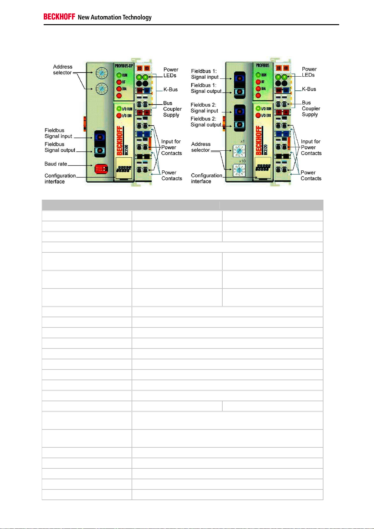
The interfaces
A Bus Coupler has six different methods of connection. These interfaces are designed as plug connectors and as
spring-loaded terminals.
Fieldbus Components 11
Page 14

Notes on the Documentation
PROFIBUS - Introduction
PROFIBUS DP
In PROFIBUS DP systems, a master (PLC, PC etc.) usually communicates with a large number of slaves (I/Os,
drives etc.). Only the master may here actively access the bus (send telegrams on its own initiative), while a DP slave
only sends telegrams when it is requested to do so by a master.
DP StartUp
Before the master and slave can cyclically exchange data, the parameter and configuration data is transmitted from
the master to the slaves during the DP StartUp phase. After the parameter and configuration data has been sent, the
master interrogates the slave's diagnostic data until the slave indicates that it is ready for data exchange. Depending
on the extent of the calculations that the slave must carry out after receiving the parameter and configuration data, it
can take up to a few seconds before it is ready for data exchange. For this reason the slave possesses the following
states:
Parameter data
The parameter data is sent from the master to the slave in the SetPrmLock request telegram. The SetPrmLock
response telegram does not contain any data, and therefore consists of a single byte, the short acknowledgement.
The parameter data consists of DP parameters (e.g. the setting of the DP watchdog or checking the IdentNumber
(unique to each DP device)), of DPV1-/DPV2 parameters and of application-specific parameters that only have to be
transmitted once during the StartUp. If an error is found in the parameter data, this is indicated in the diagnostic data,
and the slave either remains in or enters the WAIT-PRM state.
Configuration data
The configuration data is sent from the master to the slave in the ChkCfg request telegram. The ChkCfg response
telegram does not contain any data, and therefore consists of a single byte, the short acknowledgement. The
configuration data describes the assignment of the DP modules to the cyclic I/O data that is to be exchanged
between the master and slave via the Data_Exchange telegram in the cyclic data exchange phase. The sequence of
the DP modules added to a slave in the DP configuration tool determines the sequence of the associated I/O data in
the Data_Exchange telegram.
Diagnostic data
The diagnostic data is requested by the master using a SlaveDiag request telegram without any data. The slave
replies with the diagnostic data in a SlaveDiag response telegram. The diagnostic data consists of the standard DP
diagnostics (e.g. the state of the slave, the IdentNumber) and of application-specific diagnostic data.
Cyclic data exchange
The heart of the PROFIBUS DP protocol is cyclic data exchange, during which the master carries out an exchange of
I/O data with every slave during a PROFIBUS DP cycle. This involves the master sending the outputs to each slave
with a DataExchange request telegram, while the slave replies with the inputs in a DataExchange response telegram.
This means that all the output and/or input data is transmitted in one telegram, in which the DP configuration (the
sequence of DP modules) specifies the assignment of the output and/or input data to the slave's actual process data.
Diagnosis during cyclic data exchange
A slave can send a diagnostics signal to the master during cyclic data exchange. In this case, the slave sets a flag in
the DataExchange response telegram, whereby the master recognises that there is new diagnostic data in the slave.
It then fetches that data in the SlaveDiag telegram. This means that diagnostic data is not transmitted to the controller
with the cyclic I/O data in real-time, but is always at least one DP cycle later.
12 Fieldbus Components
Page 15

Notes on the Documentation
Synchronisation with Sync and Freeze
The Sync and Freeze commands in the GlobalControl request telegram (broadcast telegram) allow the master to
synchronise the activation of the outputs (Sync) or the reading of the inputs (Freeze) in a number of slaves. When the
Sync command is used, the slaves are first switched into Sync mode (a process that is acknowledged in the
diagnostic data). The I/O data is then exchanged sequentially with the slaves in the DataExchange telegram.
Transmitting the Sync command in the GlobalControl telegram then has the effect of causing the slaves to generate
the most recently received outputs. In Freeze operation a Freeze command is first sent in the GlobalControl
telegram, in response to which all the slaves latch their inputs. These are then fetched sequentially by the master in
the DataExchange telegram.
States in the master
The master distinguishes between the CLEAR state (all outputs are set to the Fail_Safe value) and the OPERATE
state (all outputs have the process value). The Master is usually switched into the CLEAR mode when, for instance,
the PLC enters STOP.
Class 1 and Class 2 DP Masters
The Class 1 master refers to the controller that carries out cyclic I/O data exchange with the slaves, while a Class 2
master is a B&B device that generally only has read access to the slaves' I/O data.
Fieldbus Components 13
Page 16

Notes on the Documentation
PROFIBUS DPV1
PROFIBUS DPV1 refers primarily to the acyclic read and write telegrams, with which data sets in the slave are
acyclically accessed. A distinction between a Class 1 and a Class 2 master is also made for DPV1. The difference
between acyclic Class 1 (C1) and Class 2 (C2) connections is that the acyclic C1 connection is established during the
DP StartUp phase of cyclic DP operation. Once the slave has reached the WAIT-CFG state it is possible for acyclic
DPV1-C1 read and write telegrams to be sent from the master to the slave, whereas the C2 connection is established
separately, independently of the cyclic DP connection. This is usually carried out by a second (C2) master so that, for
instance, a manufacturer-specific project configuration and diagnostic tool can access the slave's data.
When two masters are used, however, is must always be borne in mind that these share bus access (a token is
exchanged), so that time relationships are less favourable than in the case of a single master system.
14 Fieldbus Components
Page 17
Notes on the Documentation
3. Mounting and Wiring
Mechanical Installation
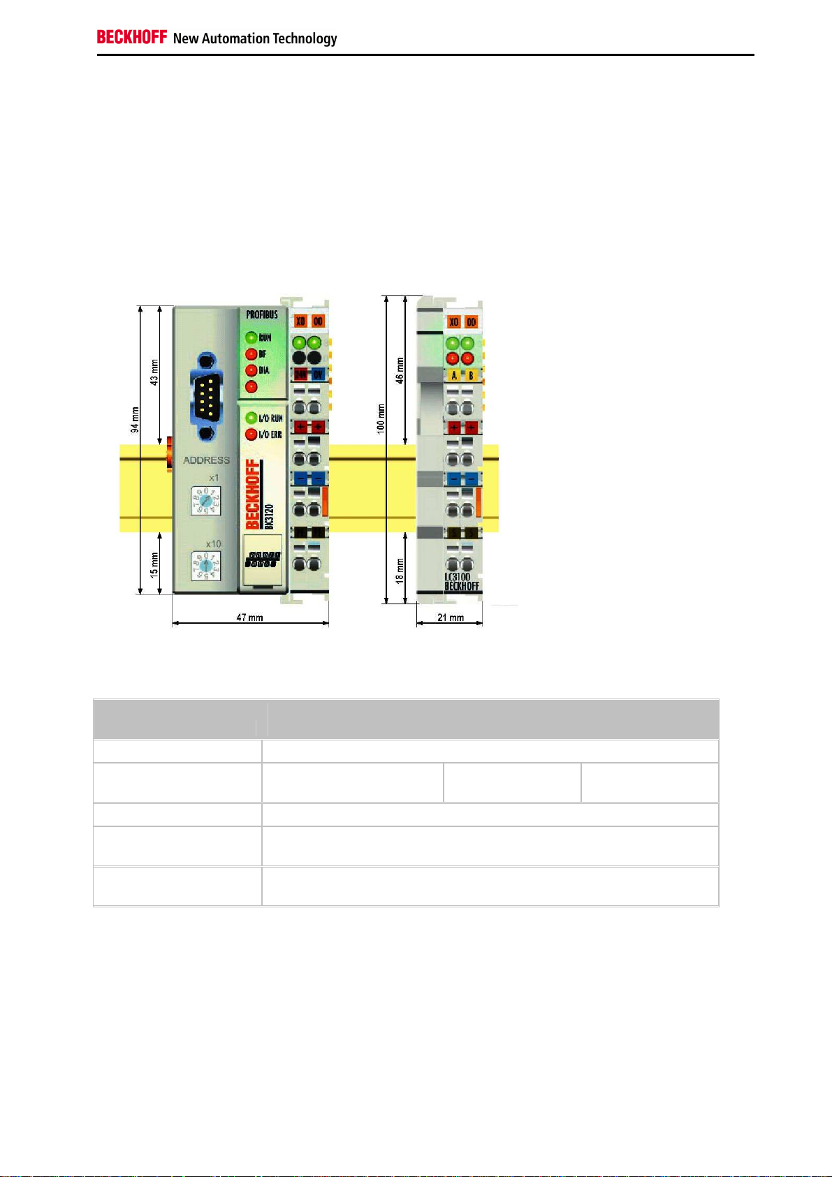
Dimensions
The system of the Beckhoff Bus Terminals is characterized by low physical volume and high modularity. When
planning a project it must be assumed that at least one Bus Coupler and a number of Bus Terminals will be used.
The mechanical dimensions of the Bus Couplers are independent of the fieldbus system.
The total width in practical cases is composed of the width of the Bus Coupler with the KL9010 Bus End Terminal and
the width of the Bus Terminals in use. Depending on function, the Bus Terminals are 12 or 24 mm wide. The front
wiring increases the total height of 68mm by about 5 to 10 mm, depending on the wire thickness.
BK30x0, BK35x0, KL3110,
Mechanical data
Material polycarbonate, polyamide (PA 6.6)
Dimensions (W x H x D) 50 mm x 100 mm x 68 mm 44 mm x 100 mm x
Mounting on 35 mm C-rail conforming to EN50022 with lock
Side by side mount. by
means of
Marking standard terminal block marking and plain language side (8 mm x 47 mm, not
BK3120 BK3150 LC3100
21 mm x 100 mm x
68 mm
double slot and key connection
BK3150)
68 mm
Fieldbus Components 15
Page 18
Notes on the Documentation
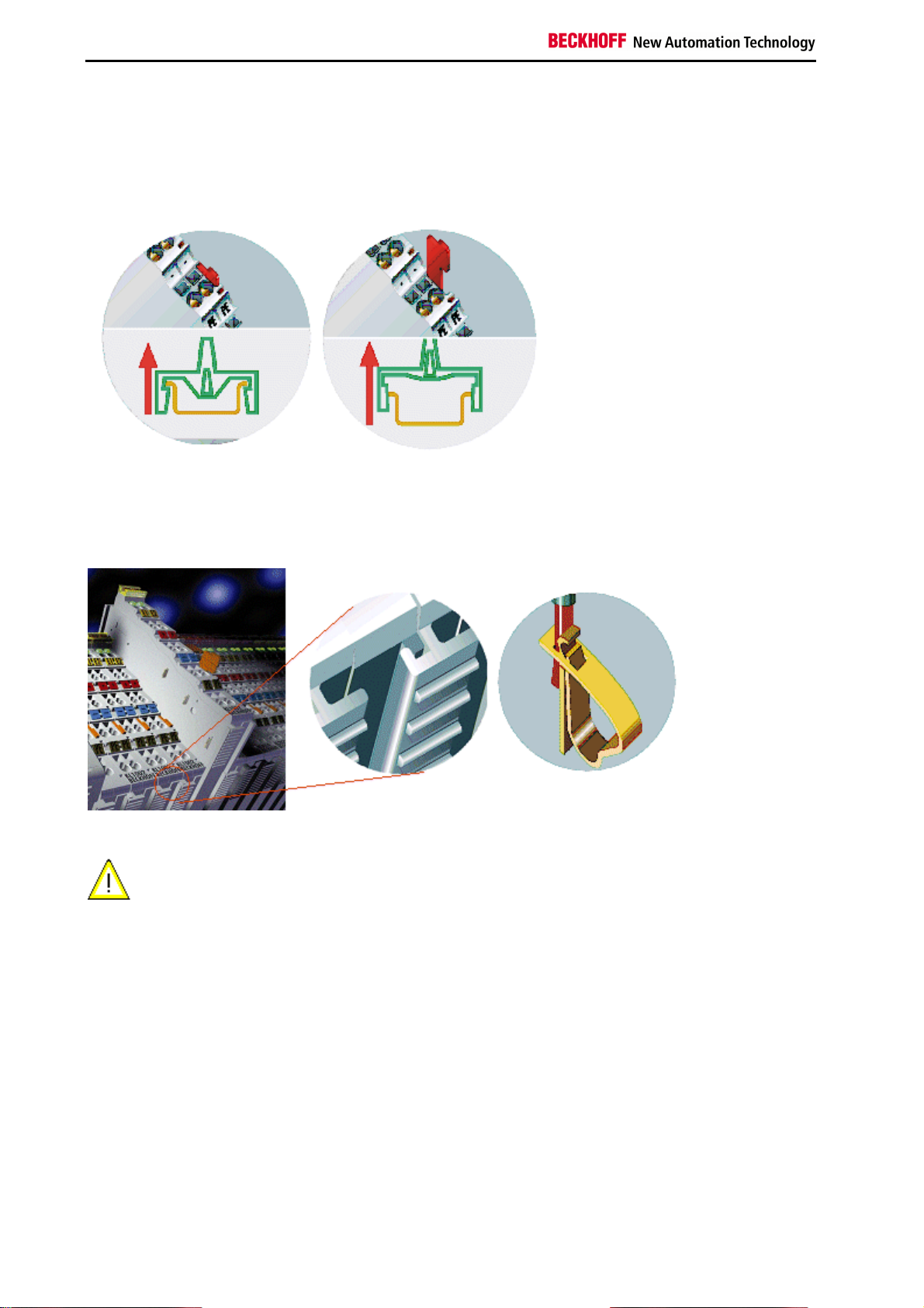
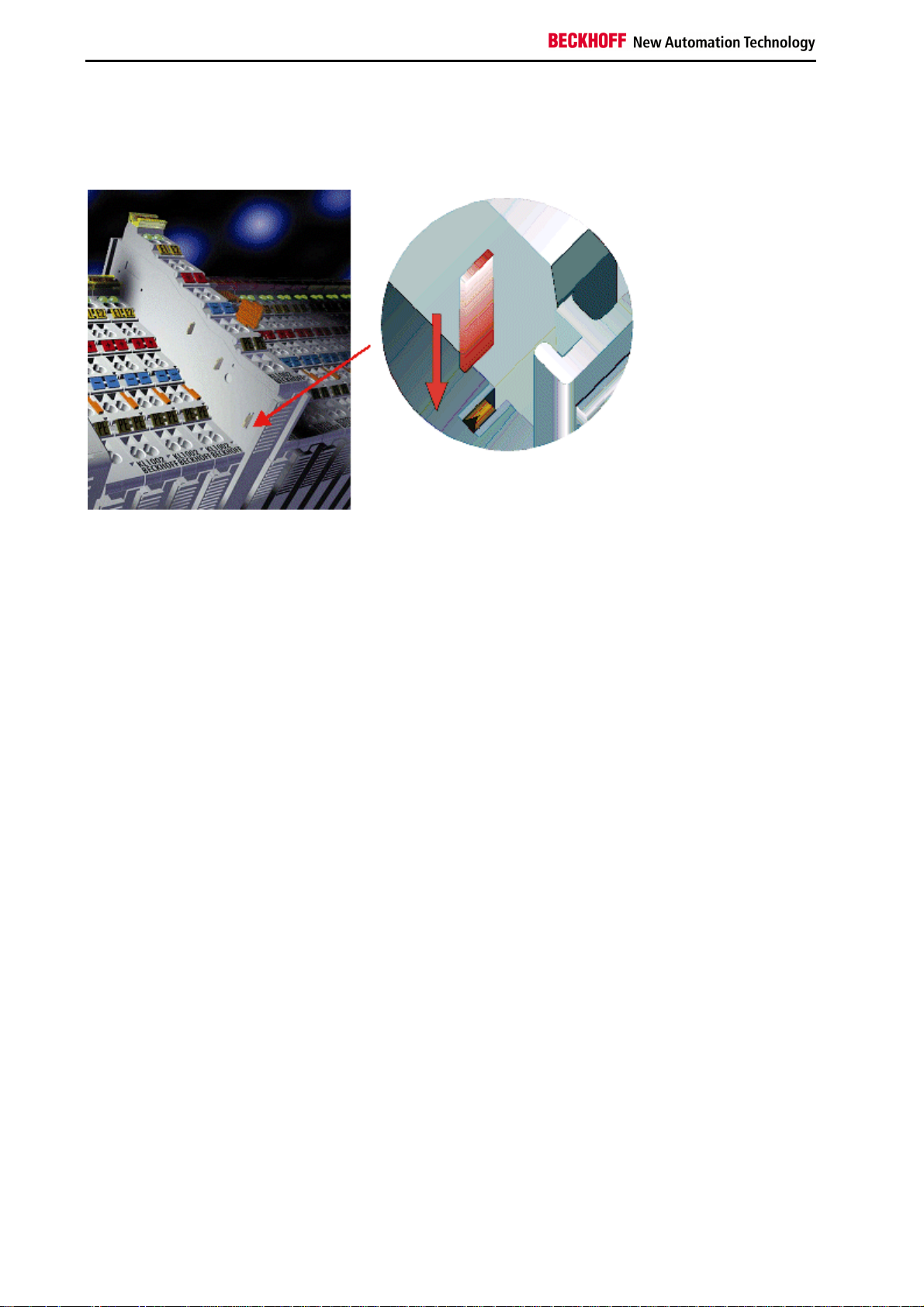
Installation
The Bus Coupler and all the Bus Terminals can be clipped, with a light press, onto a 35 mm mounting rail. A locking
mechanism prevents the individual housings from being pulled off again. For removal from the mounting rail the
orange colored tension strap releases the latching mechanism, allowing the housing to be pulled off the rail without
any force.
Up to 64 Bus Terminals can be attached to the Bus Coupler on the right hand side. When plugging the components
together, be sure to assemble the housings with groove and tongue against each other. A properly working
connection can not be made by pushing the housings together on the mounting rail. When correctly assembled, no
significant gap can be seen between the attached housings.
Insertion and removal of Bus Terminals is only permitted when switched off. The electronics
Warning
in the Bus Terminals and in the Bus Coupler are protected to a large measure against
damage, but incorrect function and damage cannot be ruled out if they are plugged in under
power.
The right hand part of the Bus Coupler can be compared to a Bus Terminal. Eight connections at the top enable the
connection with solid or fine wires from 0.08 mm² to 2.5 mm². The connection is implemented with the aid of a spring
device. The spring-loaded terminal is opened with a screwdriver or rod, by exerting gentle pressure in the opening
above the terminal. The wire can be inserted into the terminal without any force. The terminal closes automatically
when the pressure is released, holding the wire securely and permanently.
16 Fieldbus Components
Page 19
Notes on the Documentation
Wiring
Potential Groups, Insulation Testing and PE
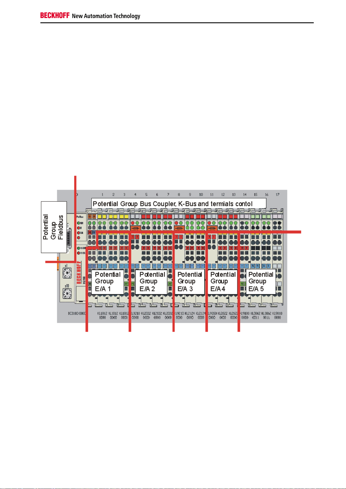
Potential groups
The Beckhoff Bus Terminals stations usually have three different potential groups:
•
The fieldbus interface is electrically isolated (except for individual Low Cost couplers) and forms the first potential group
•
Bus Coupler / Bus Terminal Controller logic, K-Bus and terminal logic form a second galvanically separated
potential group
•
The inputs and outputs are supplied via the power contacts and form further potential groups.
Groups of I/O terminals can be consolidated to further potential groups via potential supply terminals or separation
terminals.
Insulation testing
The connection between the Bus Coupler / Bus Terminal Controller and the Bus Terminals is automatically realized
by pushing the components together. The transfer of the data and the supply voltage for the intelligent electronics in
the Bus Terminals is performed by the K-Bus. The supply of the field electronics is performed through the power
contacts. Plugging together the power contacts creates a supply rail. Since some Bus Terminals (e.g. analog Bus
Terminals or 4-channel digital Bus Terminals) are not looped through these power contacts (or not completely) the
Bus Terminal contact assignments must be considered.
The potential feed terminals interrupt the power contacts, and represent the start of a new supply rail. The Bus
Coupler / Bus Terminal Controller can also be made use of to feed the power contacts.
Fieldbus Components 17
Page 20
Notes on the Documentation
PE power contacts
The power contact labelled PE can be used as a protective earth. For safety reasons this contact mates first when
plugging together, and can ground short-circuit currents of up to 125 A.
It should be noted that, for reasons of electromagnetic compatibility, the PE contacts are capacitively coupled to the
mounting rail. This can both lead to misleading results and to damaging the terminal during insulation testing (e.g.
breakdown of the insulation from a 230 V power consuming device to the PE conductor). The PE conductor to the
Bus Coupler / Bus Terminal Controller must be disconnected for the insulation testing. In order to uncouple further
feed locations for the purposes of testing, the feed terminals can be pulled at least 10 mm out from the connected
group of other terminals. In that case, the PE conductors do not have to be disconnected.
The PE power contact must not be used for other potentials.
18 Fieldbus Components
Page 21
Notes on the Documentation
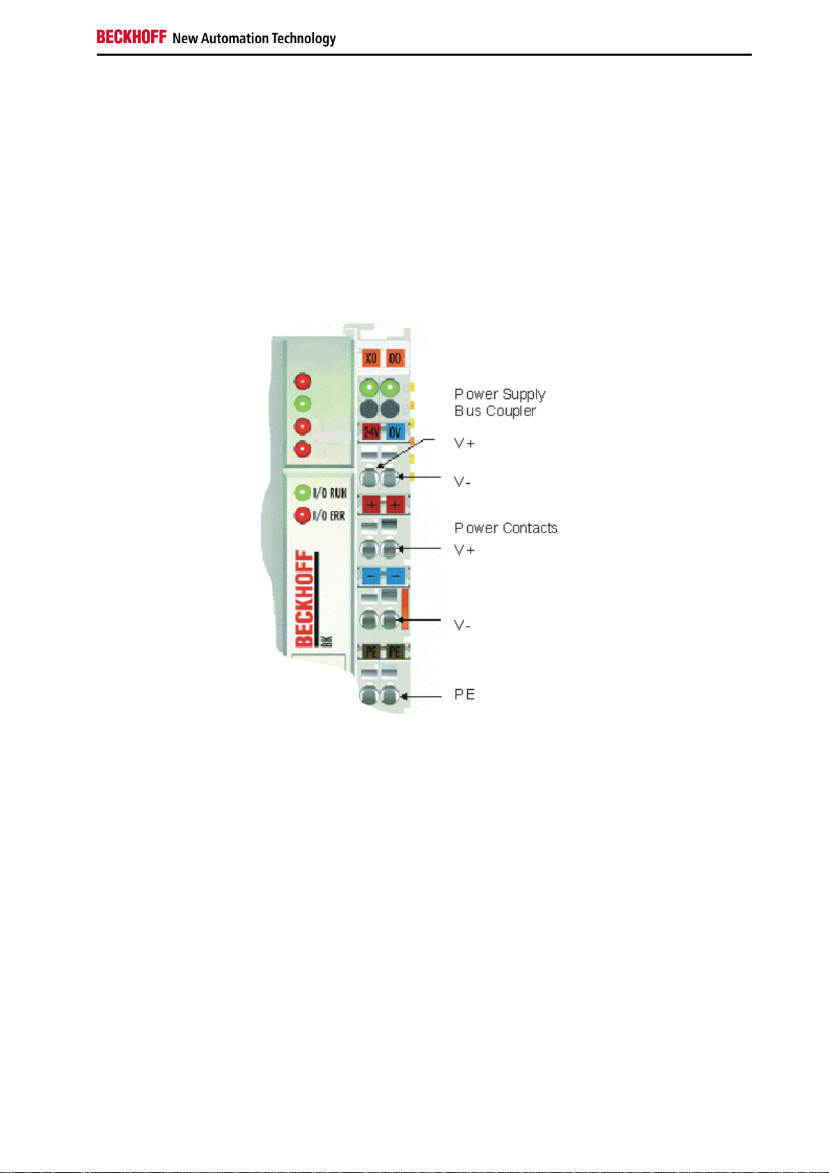
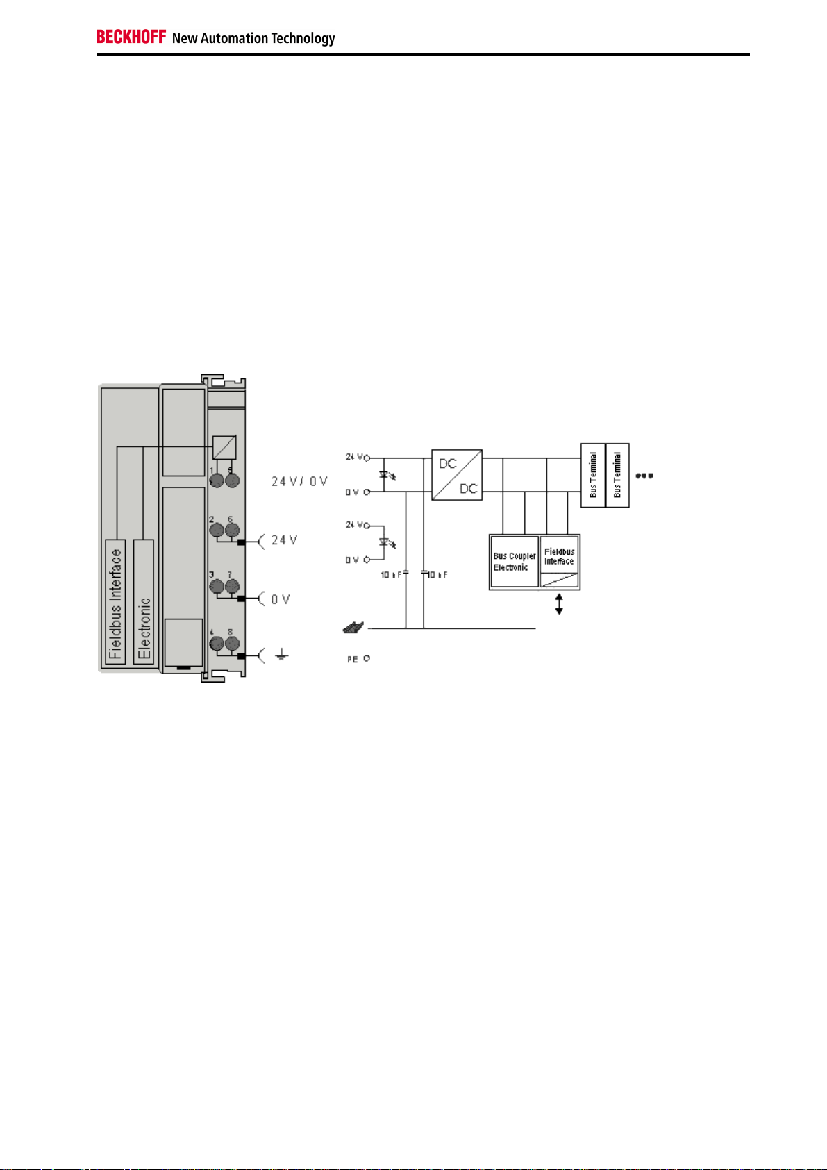
Power Supply
Bus Coupler / Bus Terminal Controller and Bus Terminal
Supply (Us)
BKxx00, BKxx10, BKxx20 and LCxxxx
The Bus Coupler / Bus Terminal Controller require a 24 VDC supply for their operation.
The connection is made by means of the upper spring-loaded terminals labeled 24 V and 0 V. This supply voltage
feeds the Bus Coupler / Bus Terminal Controller electronics and, over the K-Bus, the electronics of the Bus
Terminals. It is electrically separated from the potential of the field level.
Fieldbus Components 19
Page 22
Notes on the Documentation
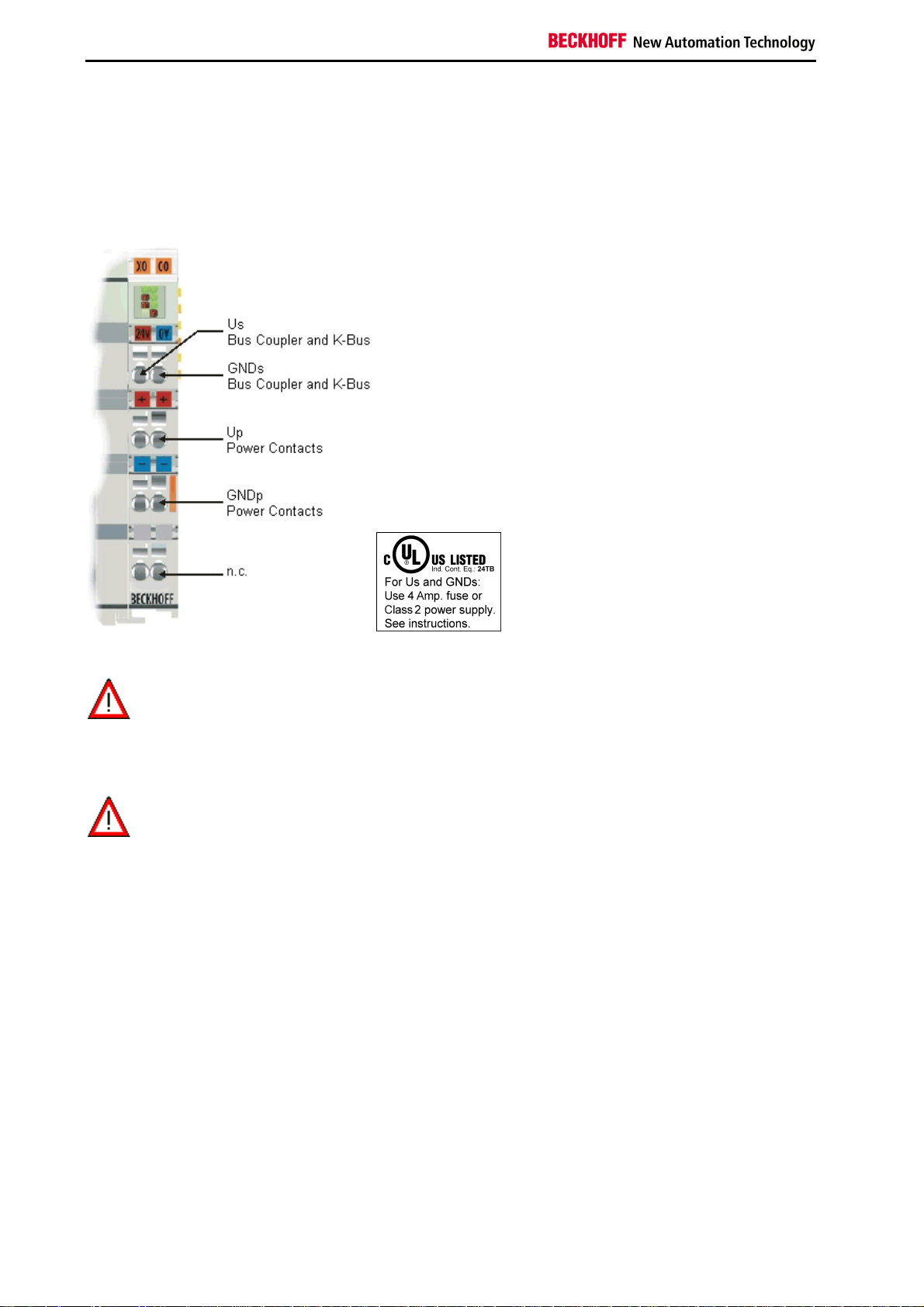
BKxx50 and BKxx51
The Bus Coupler / Bus Terminal Controller require a 24 VDC supply for their operation. To meet the UL requirements
use 4 A fuse or class 2 power supply!
The connection is made by means of the upper spring-loaded terminals labeled Us and GNDs. This supply voltage
feeds the Bus Coupler / Bus Terminal Controller electronics and, over the K-Bus, the electronics of the Bus
Terminals. It is electrically separated from the potential of the field level.
UL requirements
For the compliance of the UL requirements Us should only be supplied
•
Danger
To meet the UL requirements, Us must not be connected to unlimited power sources!
Danger
by a 24 VDC supply voltage, supplied by an isolating source and protected by
means of a fuse (in accordance with UL248), rated maximum 4 Amp.
•
by a 24 VDC power source, that has to satisfy NEC class 2.
A NEC class 2 power supply shall not be connected in series or parallel with another (class 2) power source!
Power contacts supply (Up)
The bottom six connections with spring-loaded terminals can be used to feed the supply for the peripherals. The
spring-loaded terminals are joined in pairs to a power contact. The feed for the power contacts has no connection to
the voltage supply for the Bus Coupler / Bus Terminal Controller.
The spring-loaded terminals are designed for wires with cross-sections between 0.08 mm² and 2.5 mm².
The assignment in pairs and the electrical connection between feed terminal contacts allows the connection wires to
be looped through to various terminal points. The current drawn from the power contact must not exceed 10 A for
long periods. The current carrying capacity between two spring-loaded terminals is identical to that of the connecting
wires.
Power contacts
On the right hand face of the Bus Coupler / Bus Terminal Controller there are three spring contacts for the power
contact connections. The spring contacts are hidden in slots so that they can not be accidentally touched. By
attaching a Bus Terminal the blade contacts on the left hand side of the Bus Terminal are connected to the spring
contacts. The tongue and groove guides on the top and bottom of the Bus Coupler / Bus Terminal Controller and of
the Bus Terminals enables that the power contacts mate securely.
20 Fieldbus Components
Page 23
Notes on the Documentation
Configuration and Programming Interface
The Bus Coupler / Bus Terminal Controller have an RS232 interface at the bottom of the front face. The miniature
connector can be joined to a PC and the KS2000 configuration software with the aid of a connecting cable. The
interface permits the Bus Terminals to be configured, for example adjusting the amplification factors of the analog
channels. The interface can also be used to change the assignments of the bus terminal data to the process image in
the Bus Coupler. The functionality of the configuration interface can also be reached via the fieldbus using string
communication facility.
Electrical isolation
The Bus Coupler / Bus Terminal Controller operate by means of three independent potential groups. The supply
voltage feeds the K-Bus electronics and the K-Bus itself. The supply voltage is also used to generate the operating
voltage for the fieldbus interface.
Remark: All the Bus Terminals are electrically isolated from the K-Bus. The K-Bus is thus electrically isolated from
everything else.
Fieldbus Components 21
Page 24
Notes on the Documentation
PROFIBUS Cabeling
PROFIBUS Connection
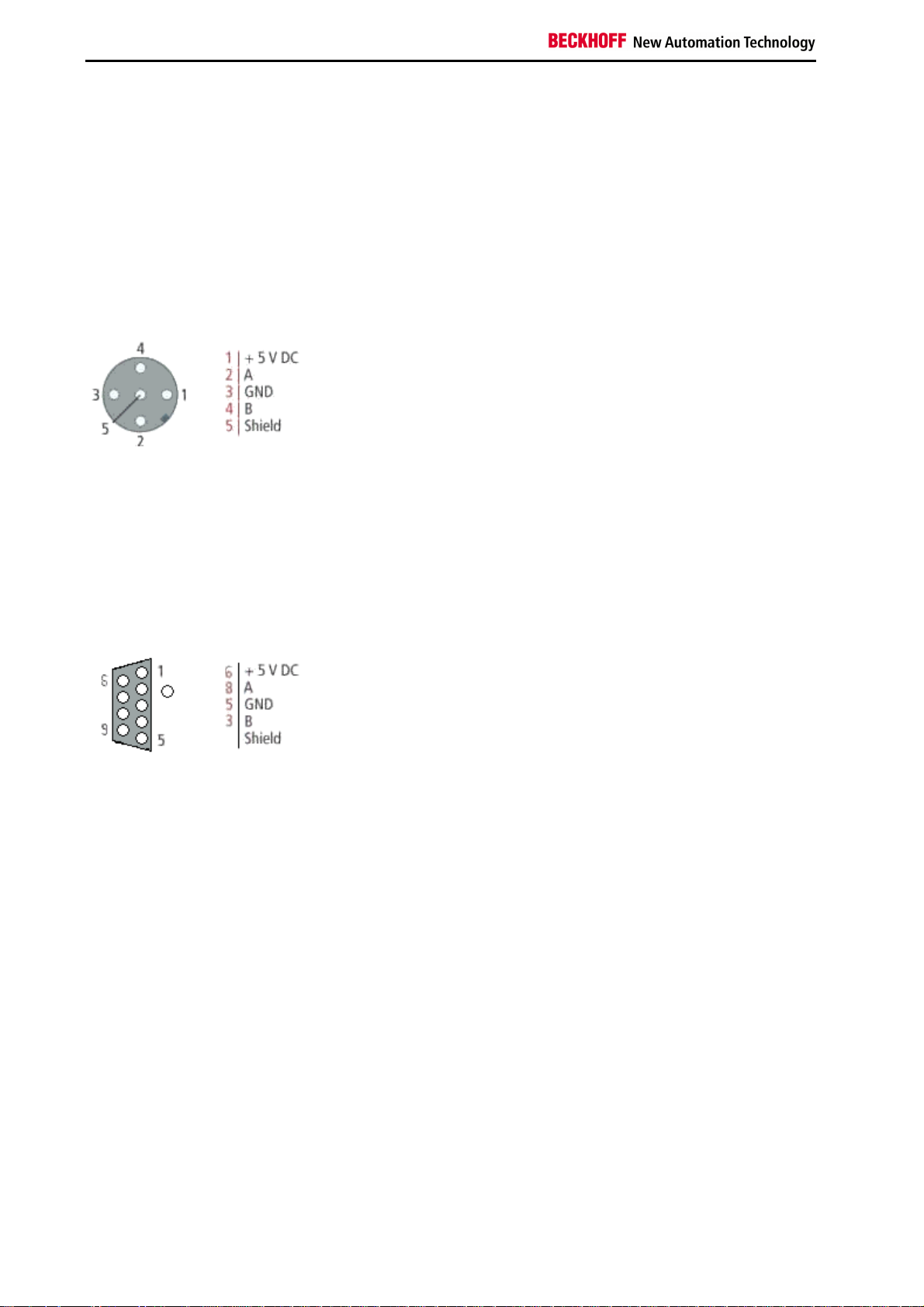
M12 circular connector
The M12 socket is inverse coded, and has five pins. Pin 1 is 5 VDC and 3 is GND for the active termination resistor.
These must never be misused for other functions, as this can lead to destruction of the device. Pin 2 and pin 4 are
the Profibus signals. These must never be swapped over, as this will prevent communication. Pin 5 is the shield, and
this is capacitatively coupled to the Fieldbus Box chassis.
M12 socket pin assignment
Nine pole D-Sub
Pin 6 is 5 VDC und Pin 5 is GND for the active termination resistor. These must never be misused for other functions,
as this can lead to destruction of the device. Pin 3 and pin 8 are the Profibus signals. These must never be swapped
over, as this will prevent communication. Shield is connected to the D-Sub housing that is coupled with lowresistance to the mounting rail.
D-Sub socket pin assignment
22 Fieldbus Components
Page 25
Notes on the Documentation
Profibus conductor colors
Profibus conductors M12 D-Sub
B red Pin 4 Pin 3
A green Pin 2 Pin 8
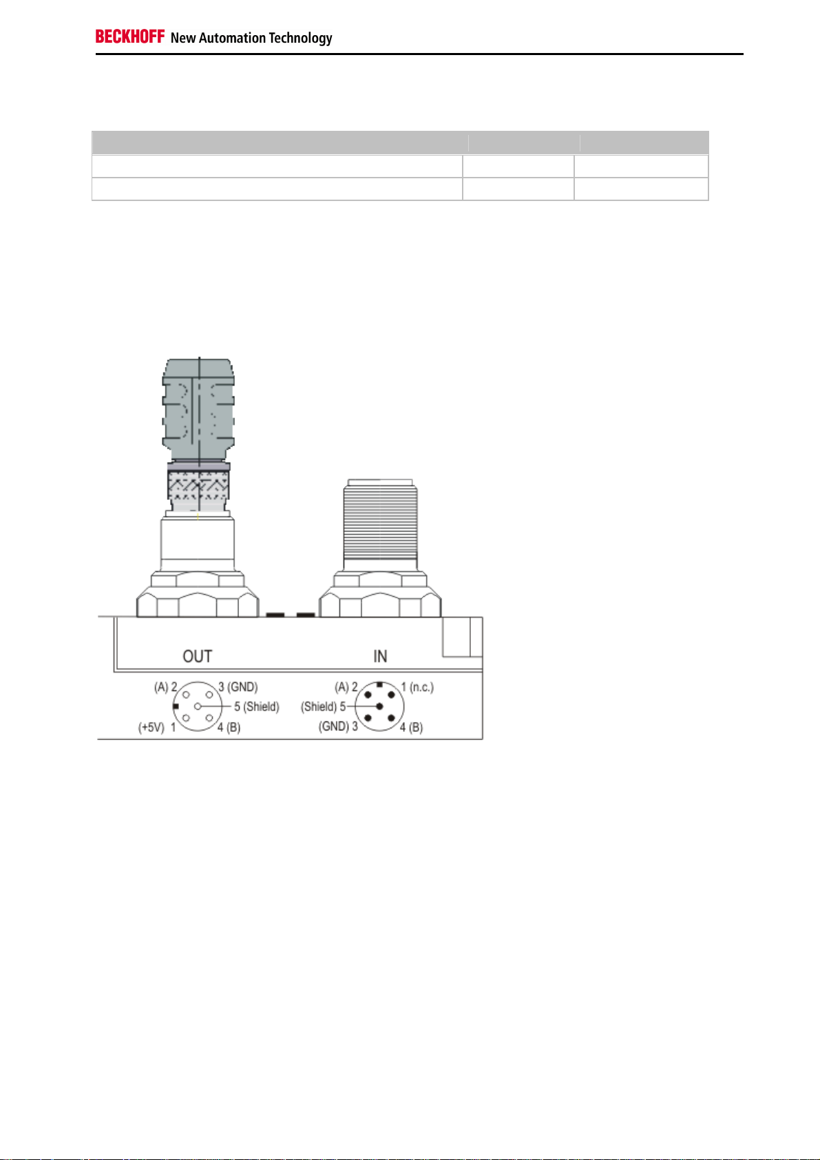
Connection of FieldbusBox modules
The connection of the Fieldbus Box modules is done direct or via a T-piece (or Y-piece).
The B318 series does have a male and female connector, that means no external T-piece is required. The supply
voltage (+5VDC) for the termination resistor is only supplied via the female M12 connector. The termination resistor
ZS1000-1610 is only available with male connector, therefore the incoming PROFIBUS line should end in a female
connector.
Two T-pieces are available:
•
ZS1031-2600 with +5VDC on male and female connector for the termination resistor
•
ZS1031-2610 with +5VDC only on the female connector
Fieldbus Components 23
Page 26

Notes on the Documentation
PROFIBUS Cabling
Physical aspects of the data transmission are defined in the Profibus standard (see Profibus layer 1: Physical Layer).
The types of area where a fieldbus system can be used is largely determined by the choice of the transmission
medium and the physical bus interface. In addition to the requirements for transmission security, the expense and
work involved in acquiring and installing the bus cable is of crucial significance. The Profibus standard therefore
allows for a variety of implementations of the transmission technology while retaining a uniform bus protocol.
Cable-based transmission
This version, which accords with the American EIA RS-485 standard, was specified as a basic version for
applications in production engineering, building management and drive technology. A twisted copper cable with one
pair of conductors is used. Depending on the intended application area (EMC aspects should be considered) the
screening may be omitted.
Two types of conductor are available, with differing maximum conductor lengths (see the RS-485 table).
RS485 - Fundamental properties
RS-485 transmission according to the Profibus standard
Network topology Linear bus, active bus terminator at both ends, stubs are possible.
Medium Screened twisted cable, screening may be omitted, depending upon the
environmental conditions (EMC).
Number of stations 32 stations in each segment with no repeater. Can be extended to 127 stations
with repeater
Max. bus length without
repeater
Max. bus length with
repeater
Transmission speed
(adjustable in steps)
Plug connector 9-pin D-Sub connector for IP20
100 m at 12 MBit/s
200 m at 1500 KBit/s, up to 1.2 km at 93.75 KBit/s
Line amplifiers, or repeaters, can increase the bus length up to 10 km. The number
of repeaters possible is at least 3, and, depending on the manufacturer, may be up
to 10.
9.6 kBit/s; 19.2 kBit/s; 93.75 kBit/s; 187.5 kBit/s; 500 kBit/s; 1500 kBit/s; 12 MBit/s
M12 round connector for IP65/67
Cabling for Profibus DP and Profibus FMS
Note the special requirements on the data cable for baud rates greater than 1.5 MBaud. The correct cable is a basic
requirement for correct operation of the bus system. If a simple 1.5 Mbaud cable is used, reflections and excessive
attenuation can lead to some surprising phenomena. It is possible, for instance, for a connected Profibus station not
to achieve a connection, but for it to be included again when the neighboring station is disconnected. Or there may be
transmission errors when a specific bit pattern is transmitted. The result of this can be that when the equipment is not
operating, Profibus works without faults, but that there are apparently random bus errors after start-up. Reducing the
baud rate (< 93,75 kBaud) corrects this faulty behavior.
If reducing the baud rate does not correct the error, then in many cases this can indicate a wiring fault. The two data
lines maybe crossed over at one or more connectors, or the termination resistors may not be active, or they may be
active at the wrong locations.
Installation is made a great deal more straightforward if pre-assembled cables from
Note
BECKHOFF are used! Wiring errors are avoided, and commissioning is more rapidly
completed. The BECKHOFF range includes fieldbus cables, power supply cables, sensor
cables and accessories such as terminating resistors and T-pieces. Connectors and cables
for field assembly are nevertheless also available.
24 Fieldbus Components
Page 27
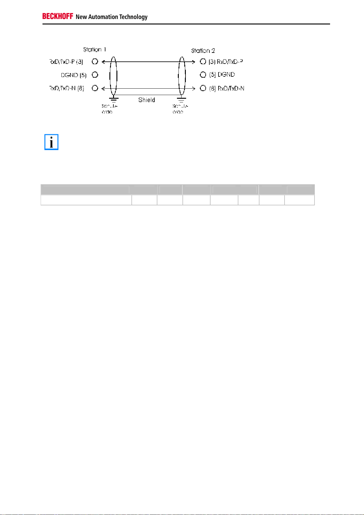
Notes on the Documentation
In systems with more than two stations all devices are wired in parallel. It is essential that
Note
the bus cables are terminated with resistors at the conductor ends in order to avoid
reflections and associated transmission problems.
Distances
The bus cable is specified in EN 50170. This yields the following lengths for a bus segment.
Baud rate in kbits/sec 9.6 19.2 93.75 187.5 500 1500 12000
Cable length in m 1200 1200 1200 1000 400 200 100
Stubs up to 1500 kbaud <6.6 m; at 12 Mbaud stub segments should not be used.
Bus segments
A bus segment consists of at most 32 devices. 126 devices are permitted in a Profibus network. Repeaters are
required to refresh the signal in order to achieve this number. Each repeater is counted as one device.
IP-Link is the subsidiary bus system for Fieldbus Boxes, whose topology is a ring structure. There is an IP master in
the coupler modules (IP230x-Bxxx or IP230x-Cxxx) to which up to 120 extension modules (IExxxx) may be
connected. The distance between two modules may not exceed 5 m. When planning and installing the modules,
remember that because of the ring structure the IP-Link master must be connected again to the last module.
Installation guidelines
When assembling the modules and laying the cables, observe the technical guidelines provided by the Profibus User
Organization (Profibus Nutzerorganisation e.V.) for Profibus DP/FMS (see www.profibus.com).
Checking the Profibus wiring
A Profibus cable (or a cable segment when using repeaters) can be checked with a few simple resistance
measurements. The cable should meanwhile be removed from all stations:
1. Resistance between A and B at the start of the lead: approx. 110 Ohm
2. Resistance between A and B at the end of the lead: approx. 110 Ohm
3. Resistance between A at the start and A at the end of the lead: approx. 0 Ohm
4. Resistance between B at the start and B at the end of the lead: approx. 0 Ohm
5. Resistance between screen at the start and screen at the end of the lead: approx. 0 Ohm
If these measurements are successful, the cable is okay. If, in spite of this, bus malfunctions still occur, this is usually
a result of EMC interference. Observe the installation notes from the Profibus User Organization (www.profibus.com).
Fieldbus Components 25
Page 28
Notes on the Documentation
4. Parameterisation and Commissioning
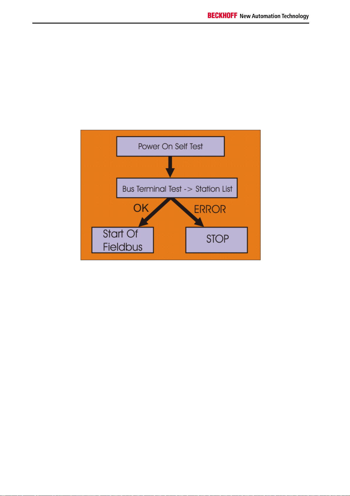
Start-up Behaviour of the Bus Coupler
Immediately after being switched on, the Bus Coupler checks, in the course of a self test, all the functions of its
components and the communication on the K-Bus. The red I/O LED blinks while this is happening After completion of
the self-test, the Bus Coupler starts to test the attached Bus Terminals (the Bus Terminal Test), and reads in the
configuration. The Bus Terminal configuration is used to generate an internal structure list, which is not accessible
from outside. In case of an error, the Bus Coupler enters the STOP state. Once the start-up has completed without
error, the Bus Coupler enters the fieldbus start state.
The Bus Coupler can be made to enter the normal operating state by switching it on again once the fault has been
rectified.
26 Fieldbus Components
Page 29

Notes on the Documentation
The Bus Coupler's UserPrmData
The following settings can be made in the Bus Coupler's UserPrmData. So that a more easily understood GSD file is
obtained in 90% of applications, some of the settings are only contained in text form in the extended GSD file, and
these are indicated in the last column by Extended. The standard settings are contained both in the standard and the
extended GSD file.
Byte Bit Value Description GSD file
0
3 6
7 0
7 4
9 2
MSAC_C1 connection is not active (default) 0 7
bin
1
MSAC_C1 connection is active (see DPV1)
bin
0
CfgData checking is active (default) 1 0
bin
1
CfgData checking deactivated (see Deactivating the CfgData checking)
bin
0
Diagnostic data is transferred in a form compatible with the BK3100 2 3
bin
1
Diagnostic data is transferred in a form compatible with DPV1 (default)
bin
0
Multi-configuration mode is not active (default) 3 3
bin
1
Multi-configuration mode is active (see Multi-configuration mode)
bin
0
K-Bus cycle counter is not active (default) 3 4
bin
1
K-Bus cycle counter is active (see K-Bus cycle)
bin
0
Dummy output byte not active (default) 3 5
bin
1
Dummy output byte is active (see K-Bus cycle)
bin
0
In multi-configuration mode, the coupler sets the Stat_Diag bit in the
bin
diagnostic data if the configuration is not consistent, and does not yet enter
data exchange (default).
1
In multi-configuration mode the coupler also enters data exchange even when
bin
the configuration is not consistent, although K-Bus cycles are not yet
executed (see Multi-configuration mode)
0
2-byte PLC interface not activated (default) 5 0
bin
1
2-byte PLC interface is active (see 2-byte PLC interface)
bin
0
Response to K-Bus error: manual K-Bus reset (default) (see K-Bus
bin
interruption)
1
Response to K-Bus error: automatic K-Bus reset
bin
0
Terminal diagnosis is not active (default) (see Terminal diagnosis) 7 1
bin
1
Terminal diagnosis is active
bin
0
Diagnostic data for digital terminals included in process image (default) (see
bin
Terminal diagnosis)
1
Diagnostic data of digital terminals not in the process image (default)
bin
0
Analog modules are mapped in compact form (only showing the input and/or
bin
output user data) (this is the default, only relevant when CfgData checking
has been deactivated, otherwise the terminals are set by means of the
CfgData) (see Deactivation of CfgData checking)
1
Analog modules are mapped in complex form (with control/status for register
bin
access and with the same data length in inputs and outputs) (only relevant
when CfgData checking has been deactivated, otherwise the terminals are set
by means of the CfgData)
0
Representation in INTEL format 9 3
bin
1
Representation in Motorola format (default)
bin
0
K-Bus mode slow FreeRun (default) (see K-Bus cycle) 9 4
bin
1
K-Bus mode fast FreeRun
bin
Standard
Extended
Extended
Extended
Extended
Extended
Extended
Extended
Standard
Standard
Standard
Extended
Standard
Standard
Fieldbus Components 27
Page 30

Notes on the Documentation
Byte Bit Value Description GSD file
0
10 0-
1
WORD alignment inactive (default) 9 5
bin
1
WORD alignment active (see WORD alignment)
bin
0
K-Bus mode is synchronous (see K-Bus cycle) 9 6
bin
1
K-Bus mode FreeRun (default)
bin
00
Reaction to PROFIBUS error: K-Bus cycle is abandoned (default, digital
bin
outputs become 0, complex outputs are set to a configured substitute value)
Extended
Standard
Standard
(see Reaction to PROFIBUS errors)
01
Reaction to PROFIBUS error: K-Bus outputs become 0
bin
10
Reaction to PROFIBUS error: K-Bus outputs remain unchanged
bin
00
10 2-
3
11 3-6 X Maximum length of the diagnostic data. Allowed values: 16, 24, 32, 40, 48,
Reaction to K-Bus error: DP data exchange is abandoned (default) (see K-
bin
Bus interruption)
01
Reaction to K-Bus error: DP inputs set to 0
bin
10
Reaction to K-Bus error: DP inputs remain unchanged
bin
Standard
Extended
56, 64 (see Terminal diagnosis)
0
12 0-
1
If K-Bus mode is synchronous: standard synchronous mode (default) (see K-
bin
Bus cycle)
01
If K-Bus mode is synchronous: synchronous mode with optimised input
bin
Extended
update (one cycle)
10
If K-Bus mode is synchronous: synchronous mode with optimised input
bin
update (two cycles)
12 4-7 0
Maximum DP buffer lengths not changed Extended
bin
12 4-7 15 The maximum DP buffer lengths are changed using the values from
Extended
UserPrmData 37-40 (see Multi-configuration mode)
13 0-7 X Delay time (in µs) high byte (see K-Bus cycle) Extended
14 0-7 X Delay time (in µs) low byte (see K-Bus cycle) Extended
15-
X Assignment of Bus Terminals 1 to 64 (see Multi-configuration mode) Extended
30 0-7
31-
- reserved Extended
36 0-7
37 0-7 X Maximum length of the input data (see Multi-configuration mode) Extended
38 0-7 X Maximum length of the output data (see Multi-configuration mode) Extended
39 0-7 X Maximum length of the diagnostic data (see Multi-configuration mode) Extended
40 0-7 X Maximum length of the configuration data (see Multi-configuration mode) Extended
41-
X Assignment of terminals 65 to 128 (see Multi-configuration mode) Extended
56 0-7
28 Fieldbus Components
Page 31

Notes on the Documentation
Technical Data - Summary
Technical data
Description BK3010 BK3110 BK3120 BK3150 BK3500 BK3520 LC3100 BC3100
Number of Bus
Terminals
Baud rate [Mbaud] 1.5 12 12 12 1.5 12 12 12
Physical basis RS 485 RS 485 RS 485 RS 485 Optical
UserPrm Data
DPV1 Services x x x x x x x x
Multi-configuration
mode
Word Align x x x x
Byte oriented Bus
Terminals
Distributed control
PLC IEC 6 1131-3 x
64 64 255 255 64 255 64 64
Optical
fibres
x x x x x x x
x x x x x
fibres
RS 485 RS 485
Fieldbus Components 29
Page 32

Notes on the Documentation
Configuration
Configuration - CfgData
The CfgData is generated from the modules inserted in the DP configuration tool. When modules are added, the
following rules are to be observed:
Sequence of DP modules to be added in the DP configuration tool
Modules for the coupler's functions
Complex function modules
Digital function modules
For TwinCAT applications, these rules are followed by the TwinCAT system manager. It adds the terminals or IE
modules in the sequence in which they are plugged in, and the modules for functions are added automatically if the
corresponding function is activated in the UserPrmData.
30 Fieldbus Components
Page 33

Notes on the Documentation
Configuration of the Coupler Modules
The DP modules for the following Bus Coupler functions are to be added first in the DP configuration tool if the
associated function is activated (if the function is not activated, the corresponding DP module is not to be added):
Function module Activation of the function
2-byte PLC
interface
K-Bus cycle
counter
Dummy output
byte
The 2-byte PLC interface is activated via the UserPrmData (byte 5, bit 0). By default it is
not active.
The K-Bus cycle counter is activated via the UserPrmData (byte 3, bit 3). By default it is
not active.
The dummy output byte is activated via the UserPrmData (byte 3, bit 5). By default it is
not active.
Fieldbus Components 31
Page 34

Notes on the Documentation
Configuration of Complex Modules
After the DP modules for the activated functions of the Bus Coupler have been added to the Bus Coupler in the DP
configuration tool, the next step is for the complex terminals (KL15xx, KL25xx, KL3xxx, KL4xxx, KL5xxx, KL6xxx,
KL8xxx) to be added in the sequence in which they are plugged in, regardless of whether digital terminals are
plugged in between the complex terminals, or of how many there may be:
Complex function
module Description
KL1501 KL1501
KL2502 KL2502
KL2521 KL2521
KL3351 compact KL3351 - only the 16 bit input value is transmitted
KL3351 complex KL3351 - 24 bits of input/output are transmitted, so
that access can be had to the terminal's registers in
addition to transmission of the 16 bit input value
KL3361 KL3361 0xFB (in GSD file)
KL3xx2 compact All KL3xx2 - only the 16 bit input value of each
channel is transmitted
KL3xx2 complex Old KL3xx2 - 24 bits of input/output are transmitted
for each channel, so that access can be had to the
terminal's registers in addition to transmission of the
16 bit input value
KL3xx4 compact All KL3xx4 - only the 16 bit input value of each
channel is transmitted
KL3xx4 complex Old KL3xx4 - 24 bits of input/output are transmitted
for each channel, so that access can be had to the
terminal's registers in addition to transmission of the
16 bit input value
KL4xx2 compact All KL4xx2 - only the 16 bit output value of each
channel is transmitted
KL4xx2 complex Old KL4xx2 - 24 bits of input/output are transmitted
for each channel, so that access can be had to the
terminal's registers in addition to transmission of the
16 bit input value
KL4xx4 compact All KL4xx4 - only the 16 bit output value of each
channel is transmitted
KL4xx4 complex Old KL4xx4 - 24 bits of input/output are transmitted
for each channel, so that access can be had to the
terminal's registers in addition to transmission of the
16 bit input value
Associated CfgData
(as hex code)
0xB4 (in GSD file)
0xB5 (alternatively)
0xF2 (alternatively)
0xB5 (in GSD file)
0xB2, 0xB2 (alternatively)
0xF2 (alternatively)
0xB2 (in GSD file)
0xF1 (alternatively)
0x51 (in GSD file)
0x50, 0x50 (alternatively)
0xB5 (in GSD file)
0xB2, 0xB2 (alternatively)
0xF2 (alternatively)
0x51 (in GSD file)
0x50, 0x50 (alternatively)
0xB5 (in GSD file)
0xB2, 0xB2 (alternatively)
0xF2 (alternatively)
0x53 (in GSD file)
0x51, 0x51(alternatively)
0x50, 0x50, 0x50, 0x50
(alternatively)
0xBB (in GSD file)
0xB5, 0xB5 (alternatively)
0xB2, 0xB2, 0xB2, 0xB2
(alternatively)
0xF5 (alternatively)
0x61 (in GSD file)
0x60, 0x60 (alternatively)
0xB5 (in GSD file)
0xB2, 0xB2 (alternatively)
0xF2 (alternatively)
0x63 (in GSD file)
0x61, 0x61 (alternatively)
0x60, 0x60, 0x60, 0x60
(alternatively)
0xBB (in GSD file)
0xB5, 0xB5 (alternatively)
0xB2, 0xB2, 0xB2, 0xB2
(alternatively)
0xF5 (alternatively)
32 Fieldbus Components
Page 35

Notes on the Documentation
Complex function
module Description
KL5001 compact KL5001 - only the 32 bit input value is transmitted
Associated CfgData
(as hex code)
0x93 (in GSD file)
0xD1 (alternatively)
KL5001 complex KL5001 - 40 bits of input/output are transmitted, so
that access can be had to the terminal's registers in
addition to transmission of the 40 bit input value
KL5051 KL5051
0xB4 (in GSD file)
0xB5 (alternatively)
0xF2 (alternatively)
0xB5 (in GSD file)
0xF2 (alternatively)
KL5101 KL5101
0xB5 (in GSD file)
0xF2 (alternatively)
KL5111 KL5111
0xB5 (in GSD file)
0xF2 (alternatively)
KL5121 KL5121
0xB5 (in GSD file)
0xF2 (alternatively)
KL5151 KL5151
0xB5 (in GSD file)
0xF2 (alternatively)
KL5302 KL5302
0xB5 (in GSD file)
0xF2 (alternatively)
KL6001 KL6001
0xB5 (in GSD file)
0xF2 (alternatively)
KL6011 KL6011
0xB5 (in GSD file)
0xF2 (alternatively)
KL6021 KL6021
0xB5 (in GSD file)
0xF2 (alternatively)
KL6051 compact KL6051 - only the 32 input bits and 32 output bits are
transmitted
KL6051 complex KL6051 - 48 input bits and 48 output bits are
transmitted, so that in addition to the 40 input bits
0xB3 (in GSD file)
0xF1 (alternatively)
0xB5 (in GSD file)
0xF2 (alternatively)
and the 40 output bits, access can also be had to the
terminal's registers
KL6061 KL6061
0xBA (in GSD file)
0xF5 (alternatively)
KL6201 (PAB 6) KL6201 - 6 bytes input and output process data is
0x35 (in GSD file)
transferred (ASI slaves 1-11)
KL6201 (PRM PAB 6) KL6201 - 6 bytes parameter interface and 6 bytes
0xF2,0x35 (in GSD file)
input and output process data is transferred (ASI
slaves 1-11)
KL6201 (PAB 16) KL6201 - 16 bytes input and output process data is
0x3F (in GSD file)
transferred (ASI slaves 1-31)
KL6201 (PRM PAB 16) KL6201 - 6 bytes parameter interface and 16 bytes
0xF2,0x3F (in GSD file)
input and output process data is transferred (ASI
slaves 1-31)
KL6801 KL6801
0xB5 (in GSD file)
0xF2 (alternatively)
KL8001 KL8001
0xBB (in GSD file)
0xF5 (alternatively)
Fieldbus Components 33
Page 36

Notes on the Documentation
Configuration of Digital Modules
After the DP modules for the activated functions of the Bus Coupler and the complex terminals (KL15xx, KL25xx,
KL3xxx, KL4xxx, KL5xxx, KL6xxx, KL8xxx) have been added to the Bus Coupler in the DP configuration tool in the
sequence in which they are plugged in, the digital terminals follow. In the case of digital terminals, it is only necessary
for the total of the digital inputs and outputs of the modules that have been added to agree with the number of digital
inputs and outputs that are plugged in:
Example:
4 x KL1408 = 32 digital input bits
2 x KL2408 = 16 digital output bits
3 x KL1114 = 12 digital input bits
2 x KL2114 = 8 digital output bits
4 x KL1012 = 8 digital input bits
1 x KL2012 = 2 digital output bits
=> 52 digital input bits and 26 digital output bits
The following combinations of DP modules could, for instance, now be added in the DP configuration tool to the Bus
Coupler:
Alternative 1
8 digital input bits
8 digital input bits
8 digital input bits
8 digital input bits
8 digital input bits
8 digital input bits
8 digital input bits
8 digital output bits
8 digital output bits
8 digital output bits
8 digital output bits
Alternative 2
56 digital input bits
32 digital output bits
Other alternatives are possible, provided the total of digital inputs is 56 bits (the next number larger than 52 divisible
by 8) and that the sum of the digital inputs is 32 bits (the next number larger than 26 divisible by 8).
34 Fieldbus Components
Page 37

Notes on the Documentation
GSD Files
The following GSD files are to be used in order to link the PROFIBUS coupler in the DP configuration tool:
Standard GSD files
The standard GSD file contains all the important and fundamental properties required for operation of any master
controller. The Bus Coupler can be parameterised in a clear and comprehensible manner with this GSD file.
Bus Coupler German English as from firmware
BK3000 BK30becf.GSD BK30becf.GSE BN
BK3010 BK3010.GSD BK3010.GSE B9
BK3100 BK31bece.GSD BK31bece.GSE BT
BK3110 BK3110.GSD BK3110.GSE B9
BK3120 BK3120.GSG BK3120.GSE B9
BK3150 BK3150.GSG BK3150.GSE B0
BK3500 BK3500.GSD BK3500.GSE B9
BK3520 BK3520.GSD BK3520.GSE B9
LC3100 LC3100.GSD LC3100.GSE B9
BC3100 BC3100.GSD BC3100.GSE C3
Extended GSD files
Additional settings are necessary for certain applications. These extended GSD files contain a large number of
additional parameterisation options. It should be noted, however, that a thorough knowledge of the master controller
along with excellent familiarity with the Beckhoff bus terminal system is necessary here.
Bus Coupler German English as from firmware
BK3010 BK3010x.GSD BK3010x.GSE B9
BK3110 BK3110x.GSD BK3110x.GSE B9
BK3120 BK3120x.GSG BK3120x.GSE B9
BK3150 BK3150x.GSG BK3150x.GSE B0
BK3500 BK3500x.GSD BK3500x.GSE B9
BK3520 BK3520x.GSD BK3520x.GSE B9
LC3100 LC3100x.GSD LC3100x.GSE B9
BC3100 BC3100x.GSD BC3100x.GSE C3
Note on the extended GSD file:
Note
The GSD file contains a maximum of 244 bytes of input, output and configuration data.
These are the maximum values. Below are the default of values and the setting options.
Fieldbus Components 35
Page 38

Notes on the Documentation
DP buffer Default Maximum size
Inputs 128 244
Outputs 128 244
Diagnostic Data 64 64
Configuration data 64 244
The sizes can be adjusted through the PrmData. The length is modified in steps of 8 bytes.
Example:
If it is desired to increase the size of the input data, other sizes must be reduced to compensate.
If we have 20 x 4 channel KL3314 thermocouples, then in compact mapping we find 20 Bus Terminals * 4 channels *
2 bytes per channel = 20 * 4 * 2 = 160 bytes
160 bytes is larger than the 128 byte default figure - settings must therefore be modified.
Set PrmData byte 12 bits 4-7 to 15 dec or 0xF hex, set byte for 37 to 160 (input data) and byte 38 to 96 (output data).
36 Fieldbus Components
Page 39
Notes on the Documentation
KS2000 Configuration Software
The KS2000 configuration software permits configuration, commissioning and parameterization of bus couplers, of
the affiliated bus terminals and of Fieldbus Box Modules. The connection between bus coupler/Fieldbus Box Module
and the PC is established by means of the serial configuration cable or the fieldbus.
Configuration
You can configure the Fieldbus stations with the Configuration Software KS2000 offline. That means, setting up a
terminal station with all settings on the couplers and terminals resp. the Fieldbus Box Modules can be prepared
before the commissioning phase. Later on, this configuration can be transferred to the terminal station in the
commissioning phase by means of a download. For documentation purposes, you are provided with the breakdown
of the terminal station, a parts list of modules used and a list of the parameters you have modified. After an upload,
existing fieldbus stations are at your disposal for further editing.
Parameterization
KS2000 offers simple access to the parameters of a fieldbus station: specific high-level dialogs are available for all
bus couplers, all intelligent bus terminals and Fieldbus Box modules with the aid of which settings can be modified
easily. Alternatively, you have full access to all internal registers of the bus couplers and intelligent terminals. Refer to
the register description for the meanings of the registers.
Commissioning
The KS2000 software facilitates commissioning of machine components or their fieldbus stations: Configured settings
can be transferred to the fieldbus modules by means of a download. After a login to the terminal station, it is possible
to define settings in couplers, terminals and Fieldbus Box modules directly online. The same high-level dialogs and
register access are available for this purpose as in the configuration phase.
The KS2000 offers access to the process images of the bus couplers and Fieldbus Box modules.
•
Thus, the coupler's input and output images can be observed by monitoring.
•
Process values can be specified in the output image for commissioning of the output modules.
All possibilities in the online mode can be used in parallel with the actual fieldbus mode of the terminal station. The
fieldbus protocol always has the higher priority in this case.
Fieldbus Components 37
Page 40

Notes on the Documentation
Configuration via TwinCAT
The TwinCAT automation software is a complete automation solution for PC-compatible computers. TwinCAT turns
any compatible PC into a real-time controller, an IEC 61131-3 Multi-PLC, NC positioning system, the corresponding
programming environment and user interface. TwinCAT supports several different PROFIBUS DP PC cards.
Beckhoff recommends the PROFIBUS DP PCI master card FC3101, which can also be obtained as a two-channel
version (FC3102).
System Manager
The TwinCAT System Manager Tool is used to configure the FC310x PROFIBUS DP PCI card. The System Manager
provides a representation of the number of programs of the TwinCat PLC systems, the configuration of the axis
control and of the connected I/O channels as a structure, and organises the mapping of the data traffic.
For applications without TwinCAT PLC or NC, the TwinCAT System Manager configures the programming interfaces
for a wide range of application programs:
•
ActiveX control (ADS-OCX) for e.g. Visual Basic, Visual C++, Delphi, etc.
•
DLL interface (ADS-DLL) for e.g. Visual C++ projects
•
Script interface (ADS script DLL) for e.g. VBScript, JScript, etc.
The TwinCAT System Manager has the following properties:
- Bit-wise association of server process images and I/O channels
- Standard data formats such as arrays and structures
- User defined data formats
- Continuous variable linking
- Drag and Drop
- Import and export at all levels
38 Fieldbus Components
Page 41
Notes on the Documentation
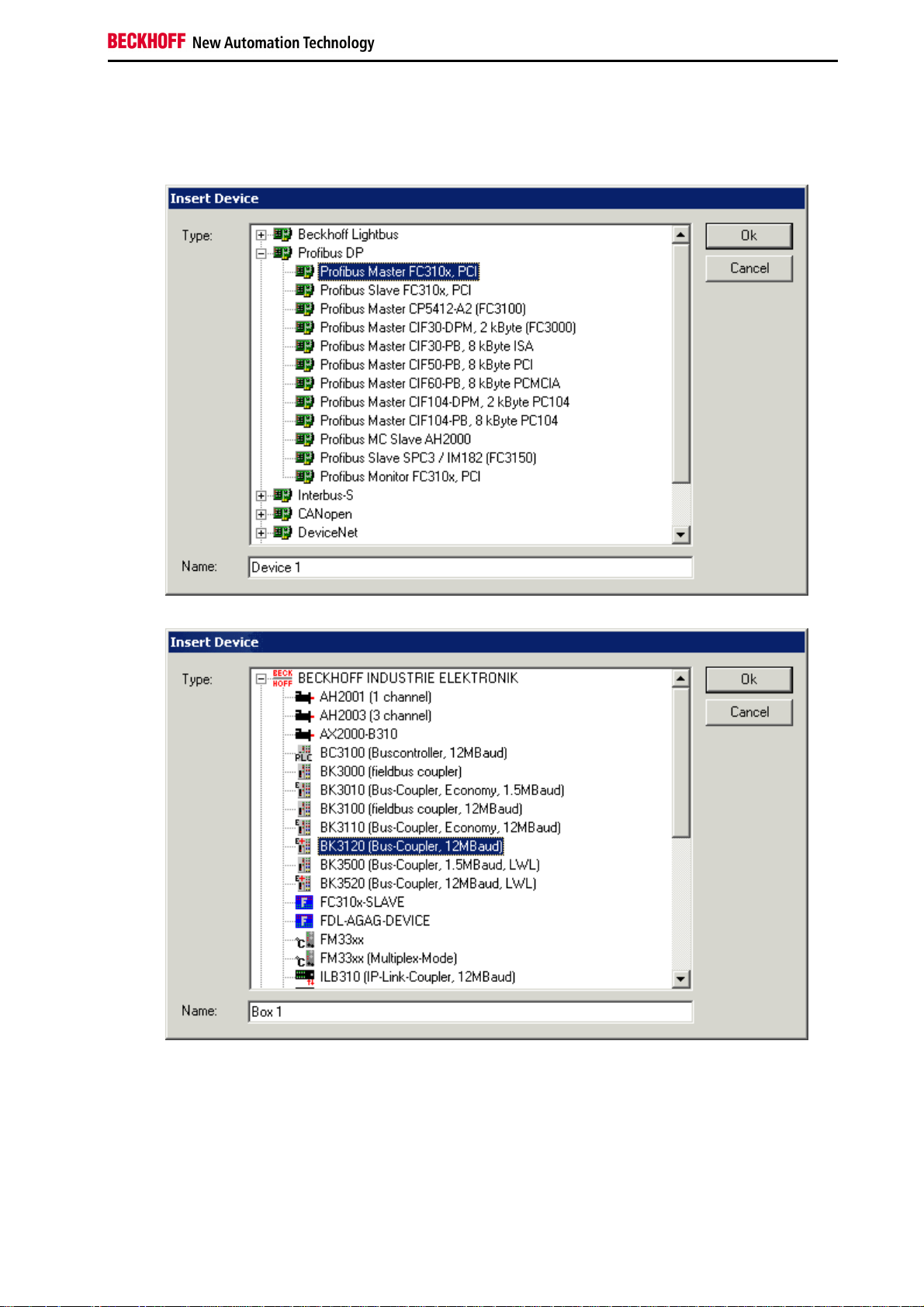
Procedure when configuring the PROFIBUS DP
input/output modules
1. The corresponding PROFIBUS DP master PC card is selected first, and inserted into the I/O configuration.
2. Following the master card, the bus nodes are then inserted:
Fieldbus Components 39
Page 42

Notes on the Documentation
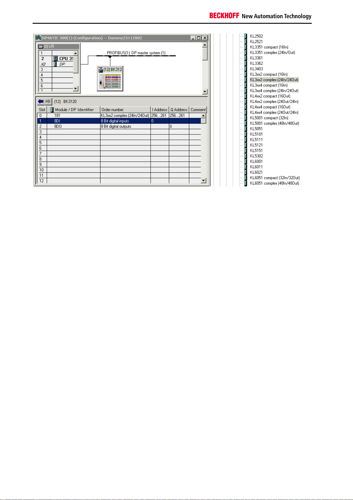
3. The appropriate Bus Terminals are now inserted at the PROFIBUS DP Bus Coupler.
40 Fieldbus Components
Page 43

Notes on the Documentation
Configuration with S7
Configuration: Siemens S7 Controller
Inserting the images
In order to assign an image to the devices in the Siemens software, they must be copied into the
Step7\S7Data\ncbmp directory.
Busklemn.bmp
Busklems.bmp
Inserting the GSD files
•
Go to Extras\Install new GSD in the hardware catalog for your Step7.
•
Select the directory in which the Beckhoff GSD is located, and import the files.
•
You will then find them in the hardware catalog under Profibus DP\Other field devices\I/O.
Fieldbus Components 41
Page 44

Notes on the Documentation
Configuration: Siemens S7 Controller BK3120
Parameter data for the BK3120
Settings
Parameter data Denomination
DPV1 service (class 1) DPV1 Services
Reaction to Bus Terminal error Reaction to Bus Terminal error
Terminal bus diagnostics PROFIBUS diagnosis
Digital terminal diagnostic data Digital Bus Terminal diagnostics
Data format Data format
K-Bus mode K-Bus update
Fast FreeRun mode Fast FreeRun mode
Reaction to DP errors Reaction to fieldbus error
Reaction to K-Bus errors Reaction to K-Bus errors
42 Fieldbus Components
Page 45

Notes on the Documentation
Configuration of the BK3120 module with digital
inputs/outputs only
Example 1:
1 x BK3120
10 x KL1xx4
1 x KL9100 (is not entered, as this Bus Terminal is entirely passive)
11 x KL2xx4
1 x KL9010 (is not entered, as this Bus Terminal is entirely passive)
The sum total of digital bytes must be added together and entered.
Digital inputs
10 x KL1xx4, i.e. 10 x 4 bits = 40 bits
40 bits / 8 = 5 bytes, i.e. 5 x 8 bits entered or 1 x 40 bits or 1 x 8 bits + 1 x 32 bits etc. (see Fig. 2 and Fig. 3)
Digital outputs
11 x KL2xx4, i.e. 10 x 4 bits = 44 bits
44 bits / 8 = 5.5 bytes - rounded up to 6 bytes, i.e. 6 x 8 bits entered or 1 x 48 bits or 1 x 8 bits + 1 x 40 bits etc. (see
Fig. 2 and Fig. 3)
Fig. 2: Example of the entry of individual bytes. Note: Each individual byte requires one byte of ConfigData. In the
BK3120 a maximum of 64 bytes of configuration data is available.
Fieldbus Components 43
Page 46

Notes on the Documentation
Fig. 3: Example of the entry of a group of associated bytes.
44 Fieldbus Components
Page 47

Notes on the Documentation
Configuration of the BK3120 module with complex and digital
input/outputs
Byte-oriented modules are the first to be mapped into the process image, and for this reason all the complex modules
must first be entered in the sequence in which they are plugged into the Bus Coupler. For some byte-oriented Bus
Terminals, it is possible to distinguish between compact and complex mapping.
Compact - only user data
Complex - user data plus status (for extended diagnosis) and control (for register communication)
Finally the digital signals are entered and rounded up to a whole byte.
Example 2.a:
1 x BK3120
2 x KL1012
1 x KL2022
1 x KL3312 compact mapping
1 x KL9010
Fig. 2a: Example of the KL3312 compact Bus Terminal
Example 2.b:
1 x BK3120
2 x KL1012
1 x KL2022
1 x KL3312 complex mapping
1 x KL9010
Fieldbus Components 45
Page 48
Notes on the Documentation
Example of the KL3312 complex Bus Terminal
46 Fieldbus Components
Page 49

Notes on the Documentation
5. PROFIBUS DP Comunication
Cyclic Data Exchange
Process Data, Process Image
The Bus Coupler includes different memory areas, each having a capacity of 256 words. Telegrams passing over the
Lightbus can specifically access any desired memory cell. The control and status bytes in the Lightbus telegrams can
be used to distinguish between two relevant regions of the memory and to address them separately. In order to
initiate a Bus Coupler update, the value in the control and status bytes must be 0x10, while the data byte must
contain the constant 80hex. It is possible to access the Bus Coupler data after this. For this purpose the control and
status byte contains the value 0x30. Two bytes can be written and two bytes can be read simultaneously with one
access. The process is described in detail in the following sections.
After being switched on, the Bus Coupler determines the configuration of the inserted input/output terminals. The
assignment of the physical slots for the input/output channels and the addresses in the process image is carried out
automatically by the Bus Coupler.
The Bus Coupler creates an internal assignment list, in which the input/output channels have a specific position in the
process image of the Bus Coupler. A distinction is made here according to inputs and outputs, and according to bitoriented (digital) and byte-oriented (analog or complex) signal processing.
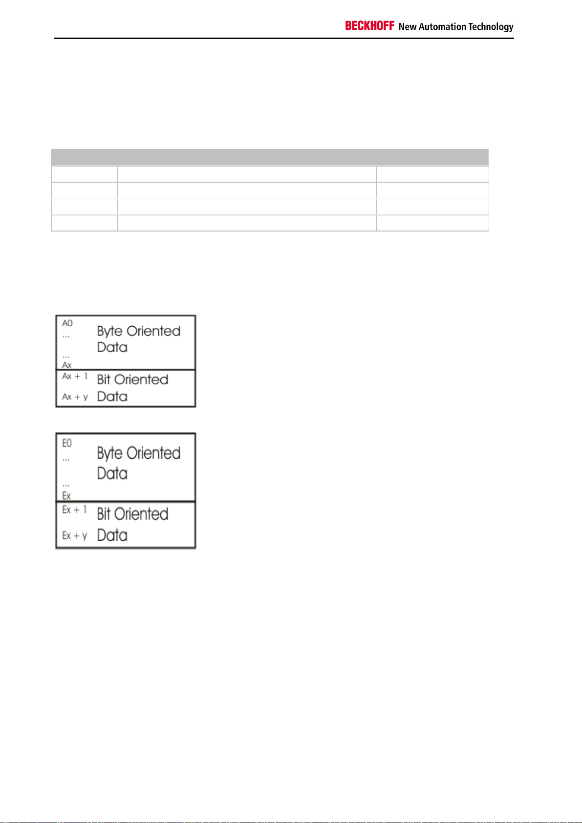
Two groups are created, one for inputs and the other for outputs. Each group has the byte-oriented channels in
ascending sequence, starting from the lowest address, and these are followed by the bit-oriented channels.
Digital signals (bit-oriented)
The digital signals are bit-oriented. This means that one bit in the process image is assigned to each channel. The
Bus Coupler creates a memory area containing the current input bits, and ensures that the bits in a second (output)
memory area dedicated to the output channels are written out immediately, following the update command.
The details of the assignment of the input and output channels to the controller's process image is explained fully with
the aid of an example in the appendix.
Analog signals (byte-oriented)
The processing of analog signals is always byte-oriented. Analog input and output values are represented in memory
by two bytes each. Values are represented in SIGNED INTEGER format. The number 0 stands for the input/output
value 0 V, 0 mA or 4 mA. The maximum value of an output or input value is represented, according to the standard
settings, by 0x7FFF. The intermediate values are correspondingly proportional. A range with a resolution of 15 bits is
not achieved for all inputs and outputs. If the actual resolution is 12 bits, the last three bits have no effect in outputs,
while as inputs they are read as 0. Each channel also has a control and status byte. The control and status byte is
the most significant byte in the most significant word. An analog channel is represented by 4 bytes in the process
image, of which 3 bytes are used. In the BK3000 and BK4000 only 2 bytes are occupied in the process image of the
corresponding bus system for each analog channel. The Bus Terminal's control and status bytes can also be
included through appropriate configuration of the Bus Coupler and Bus Terminals.
Special signals and interfaces
The Bus Coupler supports Bus Terminals with other interfaces such as RS232, RS485, incremental encoder and
others. These signals can be considered similarly to the analog signals named above. For some special signals the
bit width of 16 is not sufficient. The Bus Coupler can support any byte width. It is necessary to consider how data
consistency is ensured when accessing these values. This means that update commands must not be issued nor
must the Bus Coupler be placed into the free running mode between the accesses.
Fieldbus Components 47
Page 50
Notes on the Documentation
Default assignment of the inputs and outputs to the process image
Once it has been switched on, the Bus Coupler finds out how many Bus Terminals are inserted, and creates an
assignment list. The analog and digital channels, divided into inputs and outputs, are assembled into separate parts
of this list. The assignment starts on the left next to the Bus Coupler. The software in the Bus Coupler collects
consecutively the individual entries for each of the channels in order to create the assignment list counting from left to
right. Four groups are distinguished in the assignment:
Group Functional type of the channel Assignment
1 analog outputs byte-wise
2 digital outputs bit-wise
3 analog inputs byte-wise
4 digital inputs bit-wise
All complex Bus Terminals are represented by analog inputs or outputs.
Overview of the distribution of the process image within the Bus Coupler
Output data in the Bus Coupler
Input data in the Bus Coupler
48 Fieldbus Components
Page 51

Notes on the Documentation
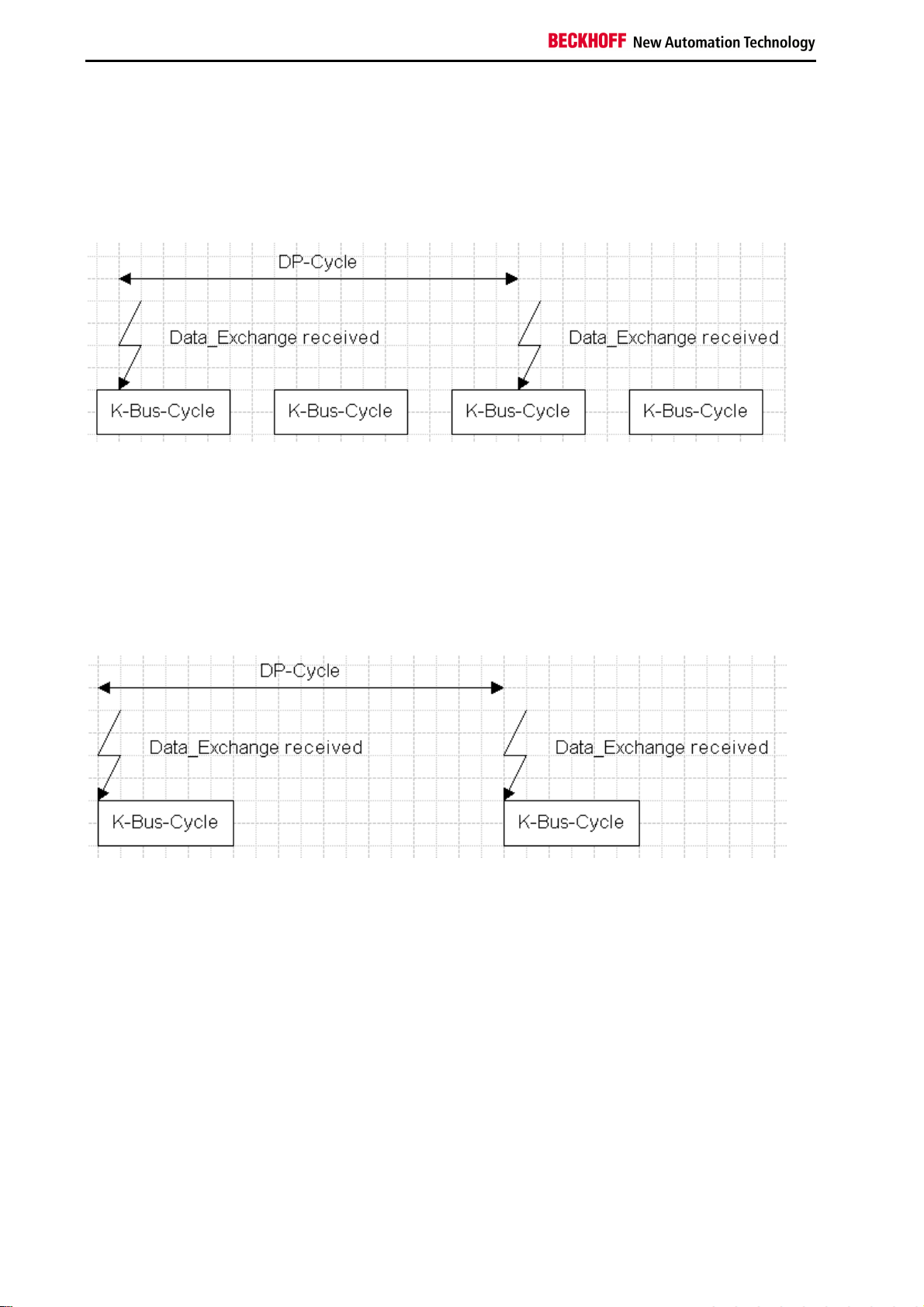
K-Bus Cycle
The K-Bus cycle can be set to run freely (FreeRun mode) or synchronously (synchronous mode) with respect to the
DP cycle. The K-Bus cycle for the DP coupler consists of the following parts:
The K-Bus cycle time can be calculated to a precision of approximately 10% by means of the following formula (4channel terminals or terminals with more than 6 bytes of data (exception: ASI terminal KL6201, which has more than
12 bytes of data) require two or more K-Bus cycles. The number of K-Bus cycles is in register ?? of table 90):
Tcyc (in µs) = number of K-Bus cycles x (600 + number of
digital channels x 2.5 + number of analog
input channels x 32 + number of analog output channels x 42)
The K-Bus cycle time can be read via DPV1. If TwinCAT is used, this is possible on the "Beckhoff" tab of
the DP coupler in the System Manager.
K-Bus modes
The K-Bus mode (the type of synchronisation between the K-Bus cycles and the DP cycle) is set via the
UserPrmData:
Byte 9, bit 4 Byte 9, bit 6 Byte 12, bit 0 Byte 12, bit
1 K-Bus mode
1
0
bin
1
1
bin
0
0
bin
0
0
bin
0
0
bin
0
bin
0
bin
0
bin
1
bin
0
bin
0
bin
0
bin
0
bin
0
bin
1
bin
bin
bin
bin
bin
bin
Slow FreeRun
Fast FreeRun
Synchronous
Synchronous with optimised input update, one
cycle
Synchronous with optimised input update, two
cycles
FreeRun mode
Slow FreeRun (default setting)
In the FreeRun mode there is no synchronisation between the K-Bus cycle and the DP cycle. It is a
characteristic feature of the Slow FreeRun mode that the K-Bus cycle is called from the main task. Acyclic
communication or events result in heavy jitter in the K-Bus cycle (KS2000, DPV1, terminal diagnosis,
etc.), because all of these functions are also called from the main task.
Fieldbus Components 49
Page 52
Notes on the Documentation
Fast FreeRun
To avoid the jitter resulting from acyclic communication or events and to achieve fast K-Bus update times,
the Fast FreeRun mode can be activated. The K-Bus cycle is called under time control from a high priority
task. Following completion of the K-Bus cycle, the lower priority tasks (DPV1, KS2000 interface, etc.) are
granted processor time for 12.5% of the duration of the foregoing K-Bus cycle, before the next K-Bus
cycle is started. In fast FreeRun mode therefore the inputs and outputs are tightly up-to-date, but are not
synchronised to the DP cycle:
Synchronous mode
As explained in the table above, there are three different synchronous modes:
Standard synchronous mode
In standard synchronous mode the K-Bus cycle is always started immediately following reception of the
Data_Exchange telegram from the DP master. The outputs are therefore generated as quickly as
possible, while the input cycles are always one DP cycle old:
It is important here to ensure that the duration of the K-Bus cycle plus approx. 20% (to allow for the lower
priority processes on the coupler) is shorter than the DP cycle time (which, under TwinCAT, means the
cycle time of the associated task).
50 Fieldbus Components
Page 53

Notes on the Documentation
Synchronous mode with optimised input update (one cycle)
In optimised input update, the start of the K-Bus cycle can be delayed following reception of the
Data_Exchange telegram, so that the inputs are more up-to-date than they are in standard synchronous
mode, whereas generation of the outputs is more severely delayed. It is important here to ensure that the
duration of the K-Bus cycle, plus the delay time, plus approx. 20% (to allow for the lower priority
processes on the coupler) is shorter than the DP cycle time (which, under TwinCAT, means the cycle
time of the associated task).
The delay time is set by means of the UserPrmData (in µs, in Motorola format). The extended GSD file of
the Bus Coupler is, however, necessary for this:
Byte Value: Description
13 Delay time (in µs) high byte
14 Delay time (in µs) low byte
Synchronous mode with optimised input update (two cycles)
In the third mode of synchronous operation, the advantages of the other two operating modes are
combined. Two K-Bus cycles are carried out within one DP cycle. The first cycle begins immediately after
reception of the Data_Exchange telegram from the master, which means that the outputs are generated
as quickly as possible. The second cycle is started after a delay time that begins after completion of the
first cycle has elapsed, so that the inputs are as recent as possible. It is important here to ensure that
twice the duration of the K-Bus cycle, plus the delay time, plus approx. 20% (to allow for the lower priority
processes on the coupler) is shorter than the DP cycle time (which, under TwinCAT, means the cycle
time of the associated task).
The delay time is set by means of the UserPrmData (in µs, in Motorola format). The extended GSD file of
the Bus Coupler is, however, necessary for this:
Byte Description
13 Delay time (in µs) high byte
14 Delay time (in µs) low byte
Fieldbus Components 51
Page 54

Notes on the Documentation
Dummy output byte
The Bus Coupler's PROFIBUS DP ASIC can only generate an interrupt after reception of a
Data_Exchange telegram if output data has been received. This means that at least one output byte must
be transferred via DP in synchronous mode. If only input terminals are plugged in, and no output data is
therefore present, a dummy output byte can be configured. It is activated in the UserPrmData, and must
be entered as the module in the CfgData. The extended GSD file for the Bus Coupler is, however,
necessary for this:
Byte Bit Value
3 5 1
bin
Description
Dummy output byte activated
It is also necessary for the dummy output byte to be configured in the CfgData before the complex
terminals:
CfgData DP modules
0x20 Dummy output byte
K-Bus cycle counter
In order for the master to be able to check reliably whether precisely one (or two) K-Bus cycles are
always being carried out during one DP cycle, a K-Bus cycle counter can be transferred in the input data
from the Bus Coupler to the master. This is incremented after each K-Bus cycle (0 is omitted, so that 1
follows after 255). The K-Bus cycle counter must be activated in the UserPrmData and entered as a
module in the CfgData. The extended GSD file for the Bus Coupler is, however, necessary for this:
Byte Bit Value
3 3 1
bin
Description
K-Bus cycle counter activated
It is also necessary for the K-Bus cycle counter byte to be configured in the CfgData before the complex
terminals:
CfgData DP modules
0x10 K-Bus cycle counter
52 Fieldbus Components
Page 55
Notes on the Documentation
DPV1 - Acyclic Data Transfer
DPV1 Interface
By default, one MSAC_C1 connection and one MSAC_C2 connection with 52 bytes of data (4 bytes DPV1 header
plus 48 bytes of user data) are supported. The MSAC_C1 connection is established along with cyclic connection, and
can be activated via the UserPrmData:
Byte Bit Value: Description
0 7 1: MSAC_C1 connection is activated
The MSAC_C2 connection can be used either by the C1 master (which communicates with the slave cyclically) or by
a C2 master (which then only communicates with the slave acyclically), and has its own establishment of connection.
The parameters at the establishment of the MSAC_C2 connection (Feature_Supported, Profile_Feature_Supported,
Profile_Ident_Number, etc.) are not examined, and the parameters of the request are mirrored in the response.
Slot_Number = 0 addresses PROFIBUS coupler data, Slot_Number > 0 addresses the data of the function
module(s).
PROFIBUS coupler data (Slot_Number = 0)
The data associated with the PROFIBUS coupler is addressed via an index:
Index Access Description
1-2 R/W Module assignment in multi-configuration mode
5 R Firmware information
9-19 R/W Device configuration (Table 9)
90 R K-Bus status (Table 90)
98 R/W Internal cycle time
99 W Commands: local bus reset, starting or stopping the internal cycle time measurement
Function module data (Slot_Number > 0)
Depending on the type of function module, access is made either to the registers (max. 4 channels, each with 64
registers) or to the parameters (only supported by a few function modules, where the quantity of data is insufficient
for the register model)
Accessing registers
Index Access Length Description
0-63 R(/W) 2 Registers 0-63 of the channel 1 in the function module
64-127 R(/W) 2 Registers 0-63 of the channel 2 in the function module
128-191 R(/W) 2 Registers 0-63 of the channel 3 in the function module
192-254 R(/W) 2 Registers 0-63 of the channel 4 in the function module
Accessing parameters
Index Access Length Description
0 R(/W) 4-32 (must be divisible by 4) Parameters 0x0000-0x0007 of the function module
1 R(/W) 4-32 (must be divisible by 4) Parameters 0x0008-0x000F of the function module
... ... ...
127 R(/W) 4-32 (must be divisible by 4) Parameters 0x03F8-0x03FF of the function module
Fieldbus Components 53
Page 56

Notes on the Documentation
Assignment of the DPV1 Slot Number
The Slot_Number = 0 addresses the data of the Bus Coupler, while Slot_Number > 0 addresses the data (registers or
parameters (KL6201)) of the complex terminals:
Slot number =
Device
0 Slot number > 0
BK3x20,
BK3500
BK3x10/LC3100 Data in Bus
Data in Bus
Coupler
Coupler
Slot_Number = 1:
first complex terminal plugged into the Bus Coupler (KL15xx, KL25xx,
KL3xxx, KL4xxx, KL5xxx, KL6xxx, KL8xxx)
Slot_Number = 2:
second complex terminal plugged into the Bus Coupler (KL15xx, KL25xx,
KL3xxx, KL4xxx, KL5xxx, KL6xxx, KL8xxx)
etc.
Not present, because neither the BK3x10 nor the LC3100 support
complex terminals.
54 Fieldbus Components
Page 57

Notes on the Documentation
DPV1 at the Coupler
Module Assignment
The multi-configuration mode is possible with a maximum of 128 modules (terminals, IE modules, etc.). The
specification of which of the modules configured in the CfgData are indeed inserted can be written with DPV1 Write
and read with DPV1 Read.
Slot number Index Length Data Description
0
1 1-15
2 1-15
Byte 0 (bit 0,1) Assignment of module 1
0: DP DataExchange (default)
2: disabled (configured module missing)
Byte 0 (bit 2,3) Assignment of module 2
0: DP DataExchange (default)
2: disabled (configured module missing)
Byte 0 (bit 4,5) Assignment of module 3
0: DP DataExchange (default)
2: disabled (configured module missing)
Byte 0 (bit 6,7) Assignment of module 4
0: DP DataExchange (default)
2: disabled (configured module missing)
Byte 1 (bit 0,1) Assignment of module 5
0: DP DataExchange (default)
2: disabled (configured module missing)
...
Byte 15 (bit 6,7) Assignment of module 64
0: DP DataExchange (default)
2: disabled (configured module missing)
Byte 0 (bit 0,1) Assignment of module 65
0: DP DataExchange (default)
2: disabled (configured module missing)
Byte 0 (bit 2,3) Assignment of module 66
0: DP DataExchange (default)
2: disabled (configured module missing)
Byte 0 (bit 4,5) Assignment of module 67
0: DP DataExchange (default)
2: disabled (configured module missing)
Byte 0 (bit 6,7) Assignment of module 68
0: DP DataExchange (default)
2: disabled (configured module missing)
Byte 1 (bit 0,1) Assignment of module 69
0: DP DataExchange (default)
2: disabled (configured module missing)
...
Byte 15 (bit 6,7) Assignment of module 128
0: DP DataExchange (default)
2: disabled (configured module missing)
Fieldbus Components 55
Page 58

Notes on the Documentation
Firmware Information
The following firmware information can be read through DPV1. The data is transferred in Intel format (low byte first):
Slot number Index Byte Description
0 5
0-1 Bus Coupler number
2-3 Software version
4-5 Manufacturer type (table 0, register 245)
6-7 Coupler type (table 0, register 246)
8-9 Bus Coupler type (table 0, register 247)
10-11 reserved
56 Fieldbus Components
Page 59
Notes on the Documentation
Terminal Composition
The terminal composition can be read by DPV1. A word is transmitted for each terminal containing the terminal
number for complex terminals (KL15xx, KL25xx, KL3xxx, KL4xxx, KL5xxx, KL6xxx, KL8xxx), and the length and type
information for digital terminals:
Bit Value Description
0 1
1 1
2-7 - reserved
8-14 X Length in bits
15 1
Digital terminal has inputs
bin
Digital terminal has outputs
bin
Always 1
bin
(indicates that the terminal is digital)
bin
Reading the terminal composition
The terminal composition is represented in the DPV1 addressing as follows:
Slot number Index Byte Description
0
9
10
11 0-1 Value for terminal 48
... ... ...
18 46-47 Value for terminal 239
19
0-1 Number of the Bus Coupler
2-3 Value for terminal 1
... ...
46-47 Value for terminal 23
0-1 Value for terminal 24
... ...
46-47 Value for terminal 47
0-1 Value for terminal 240
... ...
30-31 Value for terminal 255
Checking the terminal composition
The same data can also be accessed by a DPV1 Write. In this case the Bus Coupler compares the value that has
been written with the true value, returning a negative DPV1 Write response if the data does not agree. This permits
more precise checking of the terminal configuration than is possible by checking the CfgData.
Error codes in the write response
Error_Code_1 Error_Code_2
0xBE Number of terminals
0xBF First faulty byte in the written data
Fieldbus Components 57
Page 60

Notes on the Documentation
K-Bus Status
The K-Bus status can be read through DPV1. The data is transferred in Intel format (low byte first):
Slot
number Index Byte Description
Bit 0: Fieldbus errors
0 90
0-1
Bit 1: K-Bus error
Bit 2: Error on the Bus Terminal
Bit 3: Coupler error
2-3 In the presence of a coupler error: Error code
K-Bus error = 0: Bit length of the K-Bus 4-5
K-Bus error = 1: K-Bus error code (-> Diagnostic data)
K-Bus error = 0:
6-7
Number of terminals
K-Bus error = 1:
Bus Terminal number following which the K-Bus error is detected (-> Diagnostic
data)
58 Fieldbus Components
Page 61

Notes on the Documentation
Cycle Time Measuring
The duration of the process data cycle can be measured with DPV1. /p>
The cycle time measurement is started or stopped using DPV1 Write:
Slot number Index Length Data Description
0 99 4
0 99 4
The minimum, maximum, mean (of the last 200 cycles) and current cycle time can be read with DPV1 Read and reset
with DPV1 Write:
Slot number Index Length Data Description
0 98 8
Byte 0, 1 Minimum cycle time in µs (INTEL format, low byte first)
Byte 2, 3 Maximum cycle time in µs (INTEL format, low byte first)
Byte 4, 5 Mean cycle time in µs (INTEL format, low byte first)
Byte 6, 7 Current cycle time in µs (INTEL format, low byte first)
Byte 0: 0x04
Byte 1: 0x01
Byte 2: 0x01
Byte 3: 0x00
Byte 0: 0x04
Byte 1: 0x01
Byte 2: 0x00
Byte 3: 0x00
Start the cycle time measurement
Stop the cycle time measurement
Fieldbus Components 59
Page 62
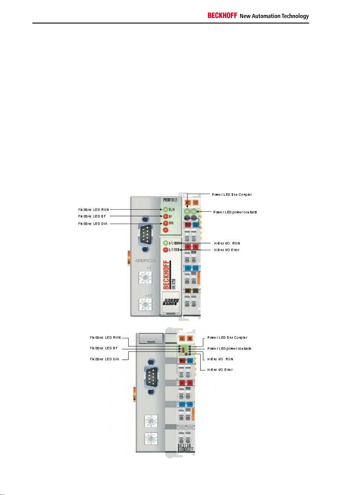
Notes on the Documentation
6. Diagnosis and Error Handling
LEDs
Overview
The Bus Coupler has two groups of LEDs for the display of status. The upper group (BK3xx0) or left hand group
(LC3100) indicates the state of the fieldbus.
On the upper right hand side of the BK3xx0 Bus Coupler are two more green LEDs that indicate the supply voltage.
The left hand LED indicates the presence of the 24 V supply for the Bus Coupler. The right hand LED indicates the
presence of the supply to the power contacts. The two K-Bus LEDs (I/O RUN, I/O ERR) are located under the
fieldbus LEDs. These indicate the operational state of the Bus Terminals and the connection to these Bus Terminals.
Fieldbus LEDs
The upper three LEDs (or the two LEDs on the left) indicate the operating state of the PROFIBUS communication:
60 Fieldbus Components
Page 63

Notes on the Documentation
BK3xx0
I/ORUN BF DIA Meaning Remedy
on off off Operating state: RUN, Inputs are read
and outputs are set
on on off,
blinking
2. Bus error with reaction to
off off off Data exchange with the master is not
off on on No bus activity Start the master, check the bus cable
off on off,
blinking
1. Bus activity, but slave is already
parameterised
PROFIBUS error:
a.) K-Bus outputs become 0 or b.) KBus outputs are retained
started
Bus error with reaction to PROFIBUS
error: K-Bus cycle is stopped
Everything is operating correctly
Start master
Check parameters, configuration (possible
error in DP start-up)
Starts the PLC
Start master, check parameters,
configuration (possible error in DP startup)
Fieldbus Components 61
Page 64
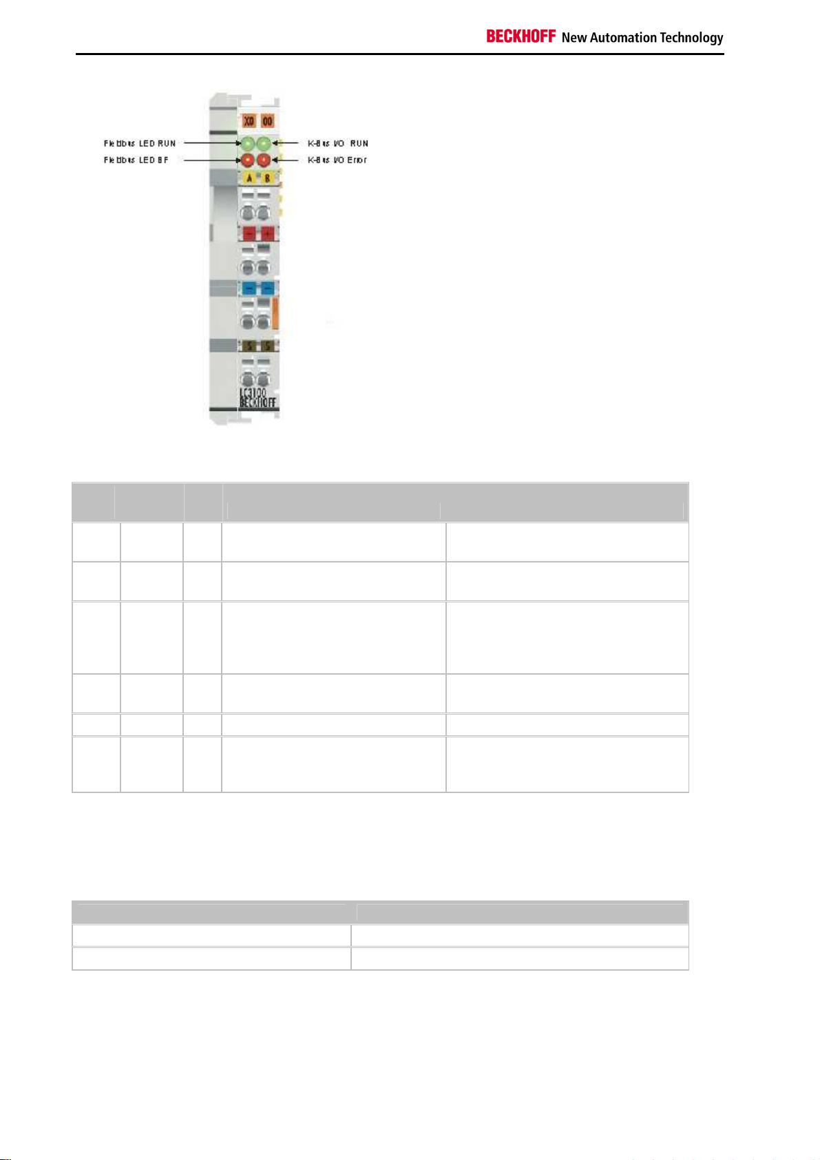
Notes on the Documentation
LC3100
I/ORUN BF RUN Meaning Remedy
on off on Operating state: RUN, Inputs are read
and outputs are set
on on,
blinking
2. Bus error with reaction to
off off on Data exchange with the master is not
off on off No bus activity Start the master, check the bus cable
off on,
blinking
on 1. Bus activity, but slave is already
parameterised
PROFIBUS error:
a.) K-Bus outputs become 0 or b.) KBus outputs are retained
started
on Bus error with reaction to PROFIBUS
error: K-Bus cycle is stopped
Everything is operating correctly
Start master
Check parameters, configuration
(possible error in DP start-up)
Starts the PLC
Start master, check parameters,
configuration (possible error in DP startup)
DIA-LED blink codes
If an error occurs in the parameterisation or configuration during DP start-up, this is indicated both through the
fieldbus LEDs and in the diagnostic data.
Blink Code
Fast blinking Start of the error code
First slow sequence
Second slow sequence
Error code
Error argument (error location)
62 Fieldbus Components
Page 65

Notes on the Documentation
K-Bus LEDs (local errors)
Two LEDs, the K-Bus LEDs, indicate the operational state of the Bus Terminals and the connection to these Bus
Terminals. The green LED (I/O RUN) lights up in order to indicate fault-free operation. The red LED (I/O ERR) flashes
with two different frequencies in order to indicate an error. The errors are displayed in the blink code in the following
way:
Error type
Error code
Error code
Persistent,
continuous
blinking
1 pulse
2 pulses
3 pulses
4 pulses
5 pulses
7 pulses
9 pulses
13 pulses
14 pulses
argument Description Remedy
- General K-bus error. Check the Bus Terminal strip
0 EEPROM checksum
error.
1 Inline code buffer
overflow.
Set manufacturer’s setting with the KS2000
software
Connect fewer Bus Terminals; too many entries
in the table for the programmed configuration
2 Unknown data type. Software update required for the coupler
0 Programmed
Check programmed configuration for correctness
configuration incorrect.
n>0 Incorrect table entry Bus
Correct table entry / Bus Coupler
Coupler / incorrect table
comparison (Bus Terminal
n).
0 K-Bus command error.
No Bus Terminal connected; attach Bus
Terminals
One of the Bus Terminals is defective; halve the
number of Bus Terminals attached and check
whether the error is still present with the
remaining Bus Terminals. Repeat until the
defective Bus Terminal is located.
0
n
K-Bus data error, break
behind Bus Terminal n.
Check whether the n+1 Bus Terminal is correctly
connected; replace if necessary.
Check whether the End Terminal 9010 is
connected.
n K-Bus error in register
Replace Bus Terminal n.
communication with Bus
Terminal n.
n BK3x10 or LC3100:
unsupported Bus
Only use digital (bit oriented) Bus Terminals, or
use a BK3120 Bus Coupler.
Terminal detected at
location n.
0 Checksum error in
Set manufacturer's setting with the KS2000.
program flash memory.
0 Runtime K-Bus command
error.
One of the Bus Terminals is defective; halve the
number of Bus Terminals attached and check
whether the error is still present with the
remaining Bus Terminals. Repeat until the
defective Bus Terminal is located.
n Bus Terminal n has the
wrong format
Start the coupler again, and if the error occurs
again then exchange the Bus Terminal.
Fieldbus Components 63
Page 66

Notes on the Documentation
Error
code
15 pulses
16 pulses
Error code
argument Description Remedy
n Number of Bus Terminals is no
longer correct
n Length of the K-Bus data (bit
Start the coupler again, and if the error occurs
again after this, use the KS2000 software to
set manufacturer’s settings.
length) is no longer correct. n =
bit length after booting
17 pulses
n Number of Bus Terminals is no
longer correct.
n = number of Bus Terminals
after booting.
18 pulses
n Bus Terminal identifier no longer
correct after reset (n = Bus
Terminal number).
Error location
The number of pulses indicates the position of the last Bus Terminal before the fault. Passive Bus Terminals, such as
a power feed terminal, are not included in the count.
64 Fieldbus Components
Page 67

Notes on the Documentation
DP Diagnostic
DP Diagnostic Data (DiagData)
The DP diagnostic data consists of six bytes of DP standard diagnosis, along with up to 238 bytes of device-specific
diagnostic data. The device-specific diagnostic data for Beckhoff slaves is represented in the DPV1 status message.
When the DP diagnostic data changes, the slave reports this fact to the master, and the master will automatically
fetch the changed diagnostic data. This means that DP diagnostic data is not included in the DP process data in realtime, but is always sent to the controller a few cycles later.
In TwinCAT the DP diagnostic data is read from the DP Master interface (FC310x, CX1500-M310) using ADS (see
the section describing Slave Diagnostics in the FC310x documentation).
DP standard diagnostic data
Offset Meaning
0x00.0 StationNonExistent: slave did not reply to the last telegram
0x00.1 StationNotReady: slave still processing the Set_Prm / Chk_Cfg telegram
0x00.2 CfgFault: slave signalling a configuration error
0x00.3 ExtDiag: extended DiagData available and valid
0x00.4 NotSupported: slave does not support a feature requested via Set_Prm or Global_Control
0x00.5 InvalidSlaveResponse: slave response not DP-compatible
0x00.6 PrmFault: slave reports a parameterisation error
0x00.7 MasterLock: slave currently exchanging data with another master
0x01.0 PrmReq: re-parameterise and reconfigure slave
0x01.1 StatDiag: slave signalling static diagnosis / DPV1 slave application not yet ready for data
exchange
0x01.2 PROFIBUS DP slave
0x01.3 WdOn: DP watchdog on
0x01.4 FreezeMode: DP slave in freeze mode
0x01.5 SyncMode: DP slave in sync mode
0x01.6 reserved
0x01.7 Deactivated: DP slave has been deactivated
0x02.0 reserved
0x02.1 reserved
0x02.2 reserved
0x02.3 reserved
0x02.4 reserved
0x02.5 reserved
0x02.6 reserved
0x02.7 ExtDiagOverflow: too much extended data present
0x03 MasterAdd: station address of master with which slave is exchanging data
0x04,
0x05
from 0x06 Device-specific diagnostic data (extended DiagData)
IdentNumber
Fieldbus Components 65
Page 68

Notes on the Documentation
Device-specific diagnostic data (DPV1 status message)
The meaning of the first 4 bytes of the DPV1 status message is specified by the DPV1 standard, while the bytes that
follow are manufacturer-specific.
Byte Bit Description
6 0-7 The length of the DPV1 status message (including this byte)
7 0-
8 0-7 SlotNumber: always 0
9 0-7 Specifier: always 0
10 0 EEPROM checksum error (can be cleared by setting the manufacturers setting through KS2000
10 4 Unknown module type
10 5 The length of the CfgData is too great (too many modules are inserted)
10 6 The length of the DP input data is too great (too many modules are inserted)
10 7 The length of the DP output data is too great (too many modules are inserted)
11 0-7 Error on an internal bus (K-Bus, IP-Link, etc.)
12 0-7 Error code on an internal bus (K-Bus, IP-Link, etc.)
13 0-7 Error argument on an internal bus (K-Bus, IP-Link, etc.)
14 0-7 DP start-up error code
StatusType: the StatusType identifies the format of the diagnostic data starting at byte 16 (0x81:
max. 64 modules, 0xA1: more than 64 modules)
7
or DPV1, followed by a power off/power on cycle)
15 0-7 DP start-up error argument
66 Fieldbus Components
Page 69

Notes on the Documentation
Errors in the modules (terminals, IP modules, IE module, etc.)
Diagnosis of the modules must be activated through the UserPrmData.
Couplers with a maximum of 64 possible modules
Byte Bit Description
16 0-5 Module number (0-63) with an error (bit 6 of the status bytes is set, except for the serial interface
modules (KL6001, KL6011, KL6021, IP6002, IP6012, IP6022, IE6002, IE6012, IE6022), where bit
3 of the status byte is set)
16 6-7 Associated channel number (0-3)`
17 0-7 Status byte of the faulty channel (bits 0-7)
18 0-5 Module number (0-63) with an error (bit 6 of the status bytes is set, except for the serial interface
modules (KL6001, KL6011, KL6021, IP6002, IP6012, IP6022, IE6002, IE6012, IE6022), where bit
3 of the status byte is set)
18 6-7 Associated channel number (0-3)`
19 0-7 Status byte of the faulty channel (bits 0-7)
... ... ...
60 0-5 Module number (0-63) with an error (bit 6 of the status bytes is set, except for the serial interface
modules (KL6001, KL6011, KL6021, IP6002, IP6012, IP6022, IE6002, IE6012, IE6022), where bit
3 of the status byte is set)
60 6-7 Associated channel number (0-3)`
61 0-7 Status byte of the faulty channel (bits 0-7)
Couplers with a maximum of more than 64 possible modules
Byte Bit Description
16 0-7 Module number (1-255) with an error (bit 6 of the status bytes is set, except for the serial interface
modules (KL6001, KL6011, KL6021, IP6002, IP6012, IP6022, IE6002, IE6012, IE6022), where bit
3 of the status byte is set)
17 6-7 Associated channel number (0-3)`
17 0-5 Status byte of the faulty channel (bits 0-5)
18 0-7 Module number (1-255) with an error (bit 6 of the status bytes is set, except for the serial interface
modules (KL6001, KL6011, KL6021, IP6002, IP6012, IP6022, IE6002, IE6012, IE6022), where bit
3 of the status byte is set)
19 6-7 Associated channel number (0-3)`
19 0-5 Status byte of the faulty channel (bits 0-5)
... ... ...
60 0-7 Module number (1-255) with an error (bit 6 of the status bytes is set, except for the serial interface
modules (KL6001, KL6011, KL6021, IP6002, IP6012, IP6022, IE6002, IE6012, IE6022), where bit
3 of the status byte is set)
61 6-7 Associated channel number (0-3)`
61 0-5 Status byte of the faulty channel (bits 0-5)
Fieldbus Components 67
Page 70

Notes on the Documentation
Errors during DP Start-up
If an error occurs in the parameterisation (UserPrmData) or configuration (CfgData) during DP start-up, this is
indicated both through the fieldbus LEDs and in the diagnostic data (DiagData).
Possible DP start-up errors are identified by an error code and an error argument.
Errors when checking the UserPrmData
Error code 1
Error code 1 indicates that a reserved bit in the UserPrmData has been set to an incorrect value, or that the function
corresponding to the bit in the UserPrmData is not supported. The error argument describes which UserPrmData
byte has been detected as containing an error (the offset of the faulty byte + 1).
Error code 3
Error code 3 indicates that a combination of functions selected in the UserPrmData is not allowed. The error
argument describes the impermissible combination.
Error code
argument Description
1 The Reaction to DP error cannot be set to "Outputs unchanged" in synchronous mode
2 The DPV1-MSAC_C1 connection has been activated by the master, but no DPV1-
MSAC_C1 connection is defined
6 The Multi-configuration mode is not allowed if Checking the CfgData is switched off
8 Synchronous mode may only be activated when at least one DP output byte is
configured
10 The optimised input cycle is only possible in synchronous mode
11 The length of the DP buffer exceeds the size of the DP RAM in the PROFIBUS ASIC
12 Fast-FreeRun mode may not be activated together with synchronous mode
Errors when checking the CfgData
Error code 2
Error code 2 indicates that a byte in the CfgData is not correct. The error argument describes which CfgData byte has
been detected as containing an error (the offset of the faulty byte + 1).
Error code 5
Error code 5 indicates that the length of the digital outputs (in bytes) calculated from the CfgData is not correct. The
error argument contains the expected byte length.
Error code 6
Error code 6 indicates that the length of the digital inputs (in bytes) calculated from the CfgData is not correct. The
error argument contains the expected byte length.
68 Fieldbus Components
Page 71

Notes on the Documentation
Error code 7
Error code 7 indicates a variety of errors when checking the CfgData. The error argument describes the error.
Error argument Description
1 The length of the CfgData received is not correct
2 The syntax of the CfgData received is not correct
3 The length of the DP input data that has been calculated from the CfgData is too large
4 The length of the DP output data that has been calculated from the CfgData is too large
Errors during slave start-up
Error code 8
Error code 8 indicates that the length of the DP buffer is greater than the size of the DP RAM in the PROFIBUS
ASIC. The error argument contains the difference (divided by 8). DP communication is deactivated.
Error code 9
Error code 9 indicates a variety of errors that may be detected as the device boots. The error argument describes the
error.
Error argument Description
1 The length of the DP input data is too great (too many modules are inserted)
2 The length of the DP output data is too great (too many modules are inserted)
3 The length of the CfgData is too great (too many modules are inserted)
Fieldbus Components 69
Page 72

Notes on the Documentation
Reaction to PROFIBUS Error
A PROFIBUS error (failure of the master, withdrawal of the PROFIBUS plug etc.) is detected after the DP watchdog
has elapsed (usually in the region of 100 ms, unless this has been deactivated in the master) or by bus timeout (the
baud rate supervision time is set to 10 s).
The reaction at the output data of the coupler can be set in the UserPrmData:
Byte Bit Value Description
00
10 0-
1
Reaction to PROFIBUS error: K-Bus cycle is abandoned (default, digital outputs become
bin
0, complex outputs are set to a planned substitute value)
01
Reaction to PROFIBUS error: K-Bus outputs become 0
bin
10
Reaction to PROFIBUS error: K-Bus outputs remain unchanged
bin
70 Fieldbus Components
Page 73

Notes on the Documentation
K-Bus Diagnostic
K-Bus Interruption
If the K-Bus is interrupted, or suffers from a relatively long malfunction, the coupler enters the K-Bus error state.
Depending on the setting made for Reaction to K-Bus error in the UserPrmData, the coupler abandons DP data
exchange and sets the Stat_Diag bit in the diagnostic data at the next DP start-up (with the consequence that DP
data exchange is not carried out), sets the DP inputs to 0, or leaves the DP inputs unchanged.
Byte Bit Value Description
00
10 2-3
When the interruption or malfunction on the K-Bus has been rectified, the setting of Response to K-Bus error in the
UserPrmData determines whether the K-Bus error state is left manually (by means of a K-Bus reset), or
automatically:
Byte Bit Value Description
Reaction to K-Bus error: DP data exchange is abandoned (default)
bin
01
Reaction to K-Bus error: DP inputs set to 0
bin
10
Reaction to K-Bus error: DP inputs remain unchanged
bin
0
Response to K-Bus error: manual K-Bus reset (default) 7 0
bin
1
Response to K-Bus error: automatic K-Bus reset
bin
Signalling the K-Bus error
A K-Bus error is indicated both on the I/O-ERR LED and in the DPV1 status message in the DP diagnostic data
(bytes 11-13).
Byte Bit Description
11 0 too many K-Bus command errors
11 1 too many K-Bus timeouts
11 2 too many K-Bus receive errors
11 3 too many K-Bus transmit errors
11 4 K-Bus reset error
11 5 general K-bus error
12 0-7 K-Bus error code
13 0-7 K-Bus error argument
K-Bus reset
A K-Bus reset can be carried out manually by means of a DPV1 Write:
Slot number Index Byte Value
0 99
0 2
1 1
2 0
3 0
Fieldbus Components 71
Page 74

Notes on the Documentation
Terminal Diagnostics
If terminal diagnosis has been activated, then each channel of a complex terminals is examined to see whether bit 6
in the status has changed (exceptions are the KL6001, KL6011 and KL6021, where the relevant bit is bit 3), and
whether the diagnostic bit of each channel of a digital terminal with diagnostics (KL12x2 or KL22x2) has changed. If
that is the case, the existence of new diagnostic data is reported to the master, and two bytes of diagnostic
information starting at byte 16 of each channel for which a diagnosis is pending are inserted (see Diagnostic data).
Terminal diagnosis can be activated in the UserPrmData:
Byte Bit Value Description
7 1 1
Terminal diagnosis is active
bin
Digital terminal diagnosis
By default, the diagnostic bits for the digital terminals that have diagnosis (KL12x2 and KL22x2) are transmitted
cyclically in the process image. These terminals occupy 4 bits each in both the input and output data. If terminal
diagnosis is active, then UserPrmData can be used to specify that only the I/O data for the digital terminals with
diagnosis (KL12x2: 2 bit inputs, KL22x2: 4 bit outputs) is to be included in the cyclic process image transfer:
Byte Bit Value Description
7 4 1
Diagnostic data of digital terminals not in the cyclic process image
bin
Real-time capacity of the diagnostic data
When making use of terminal diagnosis, it should always be borne in mind that the diagnostic data always reaches
the controller at least one cycle later, and that as a rule access also takes place through different mechanisms from
those used for cyclic process data. This means that process data can already be faulty, but the controller program is
only informed of this in the following cycle or the one after that. If the diagnostic bits of digital terminals with
diagnosis, or the status of complex terminals, is mapped into the process image, then the controller program always
has consistency between the process data and the diagnostic data. The appropriate setting therefore depends on the
way that the diagnosis is to be used. If it is only intended for diagnostic display, transmission within the cyclic process
data is unnecessary, but if on the other hand consistency between the process data and the diagnostic data is
desired, then the diagnostic data should be transmitted along with the cyclic process data.
Maximum diagnosis data length
If more terminal diagnosis data is present than is specified in the maximum diagnostic data length, then the
ExtDiagOverflow bit is set in the standard diagnostic data. Because older controllers have difficulties with the
maximum diagnostic data length of 64 bytes (which is the default setting), the maximum diagnostic data length can
be restricted in the UserPrmData:
Byte Bit Description
11 3-6 Maximum length of the diagnostic data. Allowed values: 16, 24, 32, 40, 48, 56, 64
It is only possible to set the maximum diagnostic data length in text form in the extended GSD file.
72 Fieldbus Components
Page 75
Notes on the Documentation
7. Extended Functions
2-byte PLC Interface
Checking the CfgData can be deactivated if a DP master is not capable of operating with the modules listed in the
GSD file. In that case the master can send any CfgData, and as many inputs and outputs are transferred as are
described by the CfgData.
Deactivation of the CfgData checking can also be useful if a specific address range is to be reserved in the PLC for
future extensions. In that case, more input and output data is to be transferred than is in fact necessary.
Deactivation of the CfgData check can be set in the UserPrmData:
Byte Bit Value Description
1 0 1
In general, the I/O data from the modules (terminals or IE modules) is written by the coupler in the standard
sequence (first the complex, then the digital modules), as is also the case for other fieldbus couplers; this has already
been described in connection with the structure of the process image in the coupler. The decision on a module-tomodule basis as to whether the module is mapped in compact or complex form, which would otherwise be possible
under DP, is omitted when CfgData checking is deactivated. In that case, the setting made in the UserPrmData
applies to all modules:
CfgData checking is deactivated
bin
The compact or complex mapping can be set in the UserPrmData:
Byte Bit Value Description
0
Analog modules are mapped in compact form (only with the input or output user data) 9 2
bin
1
Analog modules are mapped in complex form (including control/status for register access
bin
and the same data length in the inputs and outputs)
The extended GSD file must be used to deactivate CfgData checking and to specify compact/complex mapping
textually in the master's configuration tool.
Fieldbus Components 73
Page 76

Notes on the Documentation
Word Alignment
In order to obtain the I/O data in the controller's process image in a clear form in controllers with word-oriented
process images, it is possible to specify that word alignment is used when the coupler generates its process image.
This involves a dummy byte being inserted for every variable that is larger than one byte and which would start on an
uneven address.
Word alignment can be set in the UserPrmData:
Byte Bit Value Description
9 5 1
When using the DP modules it is necessary to ensure that only those complex modules that are identified with word
alignment are used.
The extended GSD file must be used in order to set word alignment in text form in the master's configuration tool and
to be able to select the word alignment module.
Word alignment is active
bin
74 Fieldbus Components
Page 77

Notes on the Documentation
Deactivating the CfgData Check
Checking the CfgData can be deactivated if a DP master is not capable of operating with the modules listed in the
GSD file. In that case the master can send any CfgData, and as many inputs and outputs are transferred as are
described by the CfgData.
Deactivation of the CfgData checking can also be useful if a specific address range is to be reserved in the PLC for
future extensions. In that case, more input and output data is to be transferred than is in fact necessary.
Deactivation of the CfgData check can be set in the UserPrmData:
Byte Bit Value Description
1 0 1
In general, the I/O data from the modules (terminals or IE modules) is written by the coupler in the standard
sequence (first the complex, then the digital modules), as is also the case for other fieldbus couplers; this has already
been described in connection with the structure of the process image in the coupler. The decision on a module-tomodule basis as to whether the module is mapped in compact or complex form, which would otherwise be possible
under DP, is omitted when CfgData checking is deactivated. In that case, the setting made in the UserPrmData
applies to all modules:
The compact or complex mapping can be set in the UserPrmData:
CfgData checking is deactivated
bin
Byte Bit Value Description
0
Analog modules are mapped in compact form (only with the input or output user data) 9 2
bin
1
Analog modules are mapped in complex form (including control/status for register access
bin
and the same data length in the inputs and outputs)
The extended GSD file must be used to deactivate CfgData checking and to specify compact/complex mapping
textually in the master's configuration tool.
Fieldbus Components 75
Page 78

Notes on the Documentation
Multi-Configuration Mode
Applications of the multi-configuration mode
Multi-configuration mode can be used for the following types of application. A more extensive consideration,
considering, in particular, the various implementation levels of the Bus Coupler, is given in the Requirements of a
production machine.
Creating a DP configuration for various implementation levels of the Bus Coupler
If it is desired to use one PLC program to control different implementation levels of a process, it can be valuable to
work with the same DP configuration in spite of differences between the implementation-specific terminal
configurations. In this way the address offsets in the process image do not change, nor will the general DP
configuration of the Profibus DP master have to be saved again with every new implementation level. With the multiconfiguration mode it is now possible to define a maximum configuration for the Bus Coupler, and in this case it will
only be necessary to disable those terminals that are not present in accordance with the current implementation level.
Reserved Bus Terminals
Because all the analog terminals are configured first in the DP configuration, before the digital terminals, the
consequence of inserting analog terminals at a later stage is that the address offsets of the digital terminals are
shifted. The insertion of a digital terminal within the existing terminal structure (which can, for instance, be useful if
digital terminals with different input voltages are used) also has the consequence that the offsets of the digital
terminals that follow it are shifted. If a digital terminal is inserted before the end terminal however, the offset of the
existing terminals are not shifted. With multi-configuration mode it is now possible to configure additional terminals as
reserves at any location within the terminal structure.
Assigning the Bus Terminals to freely chosen process image addresses
Because digital terminals are always grouped into bytes, which therefore means that the smallest DP configuration
module is an 8-bit module, a difficulty arises when the associated terminals are to be distributed over a number of
bytes in the PLC process image. This is because in the PLC it is usually only possible to assign addresses for each
DP configuration module. With multi-configuration mode it is now possible to configure additional digital terminals as
"dummy" terminals at any desired locations, enabling the address offsets of the other terminals to be shifted in the
PLC process image.
Setting the multi-configuration mode
Multi-configuration mode is activated via the UserPrmData:
Byte Bit Description
3 4 1: Multi-configuration mode is active
Rules for multi-configuration mode
Multi-configuration mode requires a few additional rules to be observed, in addition to those for standard
configuration:
•
Only one DP module may be configured for each analog terminal
•
The digital terminals are to be declared as KLxxxx Multi-Cfg mode modules at their true position
•
The digital terminals are to be declared after the analog modules moreover as input/output sum modules,
corresponding to their bit width, as is also the case for standard configuration in the process image.
•
All modules for the maximum configuration, including the reserve modules, are to be declared
•
Modules that are not inserted must be disabled
76 Fieldbus Components
Page 79

Notes on the Documentation
Enabling/disabling Bus Terminals
Those Bus Terminals that are present in the DP configuration, but that are not in fact plugged in, must be disabled.
This can be done in the UserPrmData, via DPV1, KS2000 or through the 2-byte PLC interface.
Making the setting through DPV1 or through the 2-byte PLC interface has the advantage that the terminal assignment
for the multi-configuration mode can usually be made directly from the PLC program, without having to change the
DP configuration of the master.
As long as the inserted Bus Terminals do not agree with the non-disabled Bus Terminals to be expected from the DP
configuration, the Bus Terminal will normally set the Stat_Diag bit in the diagnostic data, with the consequence that it
is not yet ready for cyclic data exchange.
If, however, the enabling and disabling is to be carried out via the 2-byte PLC interface, it is a precondition for
function of the 2-byte PLC interface that the coupler is in cyclic data exchange mode. For that reason it is also
possible to deactivate remaining in the Stat_Diag state:
Byte Bit Description
3 6 1: In multi-configuration mode the coupler also enters the data exchange even when the
configuration is not consistent, although K-Bus cycles are not yet executed
Enabling/disabling via UserPrmData
The assignment of the terminals (a maximum of 128 terminals is possible) is entered from byte 15 to byte 30 and
from byte 41 to byte 56 of the UserPrmData. Two bits are reserved here for each terminal, indicating whether the
relevant terminal is enabled (value 0) or disabled (value 2). If the UserPrmData is to be displayed as text in the DP
configuration tool, then the parameters Assignment of module x are to be set to DP DataExchange (enabled) or Multi-
Config. mode (disabled).
Byte Bit Description
15
... ... ...
30 6,7 Assignment for terminal 64
41 0,1 Assignment for terminal 65
... ... ...
0,1 Assignment for terminal 1
0: DP DataExchange (default)
2: disabled (Multi-Config mode)
2,3 Assignment for terminal 2
0: DP DataExchange (default)
2: disabled (Multi-Config mode)
4,5 Assignment for terminal 3
0: DP DataExchange (default)
2: disabled (Multi-Config mode)
6,7 Assignment for terminal 4
0: DP DataExchange (default)
2: disabled (Multi-Config mode)
0: DP DataExchange (default)
2: disabled (Multi-Config mode)
0: DP DataExchange (default)
2: disabled (Multi-Config mode)
56 6,7 Assignment for terminal 128
0: DP DataExchange (default)
2: disabled (Multi-Config mode)
Fieldbus Components 77
Page 80

Notes on the Documentation
Enabling/disabling via DPV1 Write
The terminals are enabled/disabled through Slot_Number 0 and Index 1 or 2:
Index Byte Bit Description
1
2
0
... ... ...
15 6,7 Assignment for terminal 64
0 0,1 Assignment for terminal 65
... ... ...
15 6,7 Assignment for terminal 128
0,1 Assignment for terminal 1
0: DP DataExchange (default)
2: disabled (Multi-Config mode)
2,3 Assignment for terminal 2
0: DP DataExchange (default)
2: disabled (Multi-Config mode)
4,5 Assignment for terminal 3
0: DP DataExchange (default)
2: disabled (Multi-Config mode)
6,7 Assignment for terminal 4
0: DP DataExchange (default)
2: disabled (Multi-Config mode)
0: DP DataExchange (default)
2: disabled (Multi-Config mode)
0: DP DataExchange (default)
2: disabled (Multi-Config mode)
0: DP DataExchange (default)
2: disabled (Multi-Config mode)
78 Fieldbus Components
Page 81

Notes on the Documentation
Enabling/disabling via the 2-byte PLC interface or through KS2000
The terminals are enabled or disabled through table 1, registers 0-31:
Register Bit Description
0
... ... ...
0,1 Assignment for terminal 1
0: DP DataExchange (default)
2: disabled (Multi-Config mode)
2,3 Assignment for terminal 2
0: DP DataExchange (default)
2: disabled (Multi-Config mode)
4,5 Assignment for terminal 3
0: DP DataExchange (default)
2: disabled (Multi-Config mode)
6,7 Assignment for terminal 4
0: DP DataExchange (default)
2: disabled (Multi-Config mode)
8,9 Assignment for terminal 5
0: DP DataExchange (default)
2: disabled (Multi-Config mode)
10,11 Assignment for terminal 6
0: DP DataExchange (default)
2: disabled (Multi-Config mode)
12,13 Assignment for terminal 7
0: DP DataExchange (default)
2: disabled (Multi-Config mode)
14,15 Assignment for terminal 8
0: DP DataExchange (default)
2: disabled (Multi-Config mode)
31 14,15 Assignment for terminal 128
0: DP DataExchange (default)
2: disabled (Multi-Config mode)
It can happen under multi-configuration mode that the CfgData exceeds 64 bytes. In such a
Note
case, the CfgData must be enlarged.
Fieldbus Components 79
Page 82

Notes on the Documentation
Changing the Size of the Process Data
Exceeding the input data length (InputData)
By default, a maximum of 128 bytes of input data is set on the Bus Coupler.
The maximum length of the DP buffer can be changed. The amount, however, by which one length is increased must
be taken away from another, and it must be noted that the sizes can only be changed in 8-byte steps:
Exceeding the output data length (OutputData)
By default, a maximum of 128 bytes of output data is set on the Bus Coupler.
The maximum length of the DP buffer can be changed. The amount, however, by which one length is increased must
be taken away from another, and it must be noted that the sizes can only be changed in 8-byte steps:
Exceeding the configuration data length (CfgData)
By default, a maximum of 64 bytes of configuration data is set on the Bus Coupler. Normally, this is only a problem in
very rare cases. In multi-configuration mode, however, this limit is reached with no more than a 30 digital terminals,
because each KLxxxx MultiCfgMode module occupies two bytes in the configuration data, on top of which there is at
least one sum byte for digital inputs or for digital outputs.
The maximum length of the DP buffer can be changed. The amount, however, by which one length is increased must
be taken away from another, and it must be noted that the sizes can only be changed in 8-byte steps:
Maximum DP buffer sizes
DP buffer Maximum sizes under default settings
Inputs 128 bytes
Outputs 128 bytes
Diagnostic data 64 bytes
Configuration data 64 bytes
Setting via the 2-BYTE PLC interface or KS2000
The maximum DP buffer sizes can be modified in Table 100, although it is necessary for the Bus Coupler to be reset
(power off/power on, or a software reset) before the new value is adopted:
Register Description
2 maximum length of input data
3 maximum length of output data
4 maximum length of diagnosis data
5 maximum length of configuration data
80 Fieldbus Components
Page 83

Notes on the Documentation
Setting via UserPrmData
The Bus Coupler's reset is carried out automatically if the DP buffers are set using UserPrmData:
Byte Bit Description
12 4-7 15 dec or 0xF hex: the maximum DP buffer lengths are changed using the values from
UserPrmData 37-40
37 0-7 maximum length of input data
38 0-7 maximum length of output data
39 0-7 maximum length of diagnosis data
40 0-7 maximum length of configuration data
Example 1: Not enough configuration data
128 bytes input
128 bytes output
80 bytes CfgData
48 bytes diagnosis data
Example 2: Not enough input data
160 bytes input
96 bytes output
64 bytes CfgData
64 bytes diagnosis data
Fieldbus Components 81
Page 84

Notes on the Documentation
Implementation Levels of the Bus Coupler in MultiConfiguration Mode
Structure of a production machine
Production machines often consist of a machine part that is always present in the machine and of machine
extensions that may be added as options. This division also usually applies as well both to the software (the control
program) and to the hardware (the necessary process signals via Beckhoff Bus Terminals) associated with the
machine. A machine, with machine extensions A, B and C, whose process signals are to be read or output over the
PROFIBUS DP through Beckhoff Bus Couplers BK3110, BK3120 or BK3520, could be structured as follows:
The machine illustrated consists of a controller (e.g. TwinCAT, S7-400, etc.), a PROFIBUS DP master interface (e.g.
FC3101, CP???, etc.) that sends or receives the process signals over the PROFIBUS DP, and of Bus Couplers with
Bus Terminals that form the interface to the machine process. The areas shown in grey relate to machine parts that
are always present. The machine extensions A, B and C are shown in red, green and blue. It can be seen that each
machine extension is associated both with software modules within the control program and process signals that are
connected to the controller via Bus Terminals.
Because the machine builder will not want to maintain eight different control programs for all possible combinations of
the machine extensions, it is helpful if the control program is designed in such a way that the necessary software
modules are activated according to whichever machine extensions are in fact being used. In order to create a control
program suited to all implementation levels of the machine it is however necessary for the same process signals
always to appear at the same addresses in the controller's process image, independently of which process signals
are in fact present in the relevant implementation level. For conventional DP slaves, a different configuration of the
PROFIBUS DP master interface is necessary in such cases. The following sections explain how this problem can be
solved with Beckhoff Bus Couplers, using a single configuration of the PROFIBUS DP master interface.
The advantage of this solution is that two machine configurations only differ in terms of the hardware used (machine
components and Bus Terminals), but not in terms of the software. If the machine is upgraded, it is only necessary for
the additional Bus Terminals to be inserted and wired-up, and for the relevant extension to be activated (e.g. via the
man-machine interface to the machine). Software changes are no longer required.
82 Fieldbus Components
Page 85

Notes on the Documentation
Process image interfaces
The interfaces between controller, PROFIBUS DP master interface, Bus Coupler and Bus Terminals form process
images, in which the process signals are stored according to certain algorithms:
The process signals of a DP slave (Bus Coupler BK3110, BK3120 or BK3520) are always transferred in a
Data_Exchange telegram, in which the outputs are sent by the DP master and the inputs are received in the
associated telegram response. In the PROFIBUS DP master interface, the process images exchanged with the Bus
Couplers are mapped to the process images of the control according to a mapping rule.
Fieldbus Components 83
Page 86

Notes on the Documentation
Process images of the machine configurations
As shown in the two examples in the figure below, the mapping rule in the PROFIBUS DP master interface changes,
depending on which machine extensions are used (there are two examples here):
In order to solve the problem of the changed mapping rule, a facility is provided in the BK3110, BK3120 and BK3520
Bus Couplers through which the mapping can be carried out in the Bus Coupler (multi-configuration mode), so that
they always exchange the same process image with the PROFIBUS DP master, independently of the Bus Terminals
present:
84 Fieldbus Components
Page 87

Notes on the Documentation
Setting the Bus Terminal extension in the Bus Coupler
So that the same process image can always be transferred between the PROFIBUS DP master and the Bus Coupler,
independently of the implementation level of the machine or of the Bus Terminals, the maximum Bus Terminal
implementation for the Bus Coupler is always configured in the PROFIBUS DP master under multi-configuration
mode. This PROFIBUS DP configuration is sent from the PROFIBUS DP master to the Bus Coupler when the
PROFIBUS DP bus is starting up. This then compares the received PROFIBUS DP configuration with the bus
terminals that are actually present.
If the Bus Coupler is not already being operated with the maximum Bus Terminal implementation level, the
PROFIBUS DP configuration will not agree with the Bus Terminal structure that it finds. So that the Bus Coupler can
nevertheless represent the process signals from the connected Bus Terminals in the process image that is to be
exchanged with the PROFIBUS DP master, the mapping rule is now required.
Because the Bus Coupler maps the process signals from the Bus Terminals into the DP process image according to
a fixed algorithm (first complex, then digital terminals, each in the sequence in which they are plugged in), the only
information that is missing is that of which of the Bus Terminals that are included in the PROFIBUS DP configuration
are indeed truly present. This information can be transmitted via the acyclic DPV1 Write, or through the 2-byte PLC
interface for those PROFIBUS DP master interfaces that do not support PROFIBUS DPV1. The acyclic DPV1 Write is
usually available through function blocks (TwinCAT: ADS-Write, S7 400: SFB 52 (read) and SFB53 (write)) from the
controller program. The 2-byte PLC interface of the Bus Coupler is mapped directly into the controller's process
image. As soon as a machine extension is activated or deactivated, the controller program can therefore activate or
deactivate the associated Bus Terminals.
Example as above, where deactivated terminals are marked in yellow:
Fieldbus Components 85
Page 88

Notes on the Documentation
State transitions in the Bus Coupler
If the PROFIBUS DP configuration received does match the Bus Terminal configuration in multi-configuration mode,
the Bus Coupler sets the "static diagnostics" bit in the PROFIBUS DP diagnostic data and delays the execution of a
terminal bus cycle (I/O RUN LED remains off). As soon as the terminal assignment (activated/not activated) has been
written by the PROFIBUS DP master, the Bus Coupler again carries out an examination of the PROFIBUS DP
configuration, and automatically enters cyclic data exchange (the "static diagnosis" bit in PROFIBUS DP diagnostic
data is cleared, and the terminal bus cycle is executed cyclically (the I/O-RUN LED goes on during the terminal
cycle)). Furthermore, the terminal assignment is stored in the non-volatile memory of the Bus Coupler, so that during
a restart of the PROFIBUS DP, the PROFIBUS DP master does not have to write the terminal configuration again.
86 Fieldbus Components
Page 89
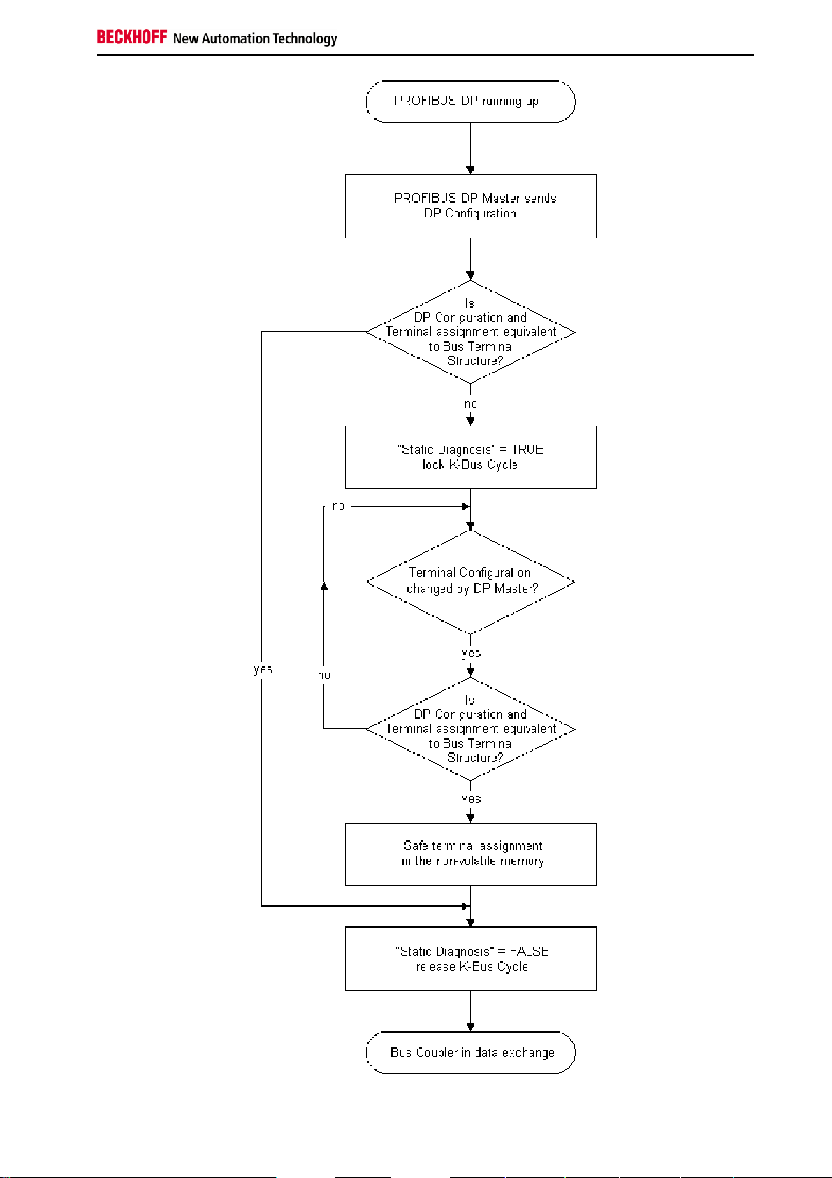
Notes on the Documentation
Fieldbus Components 87
Page 90
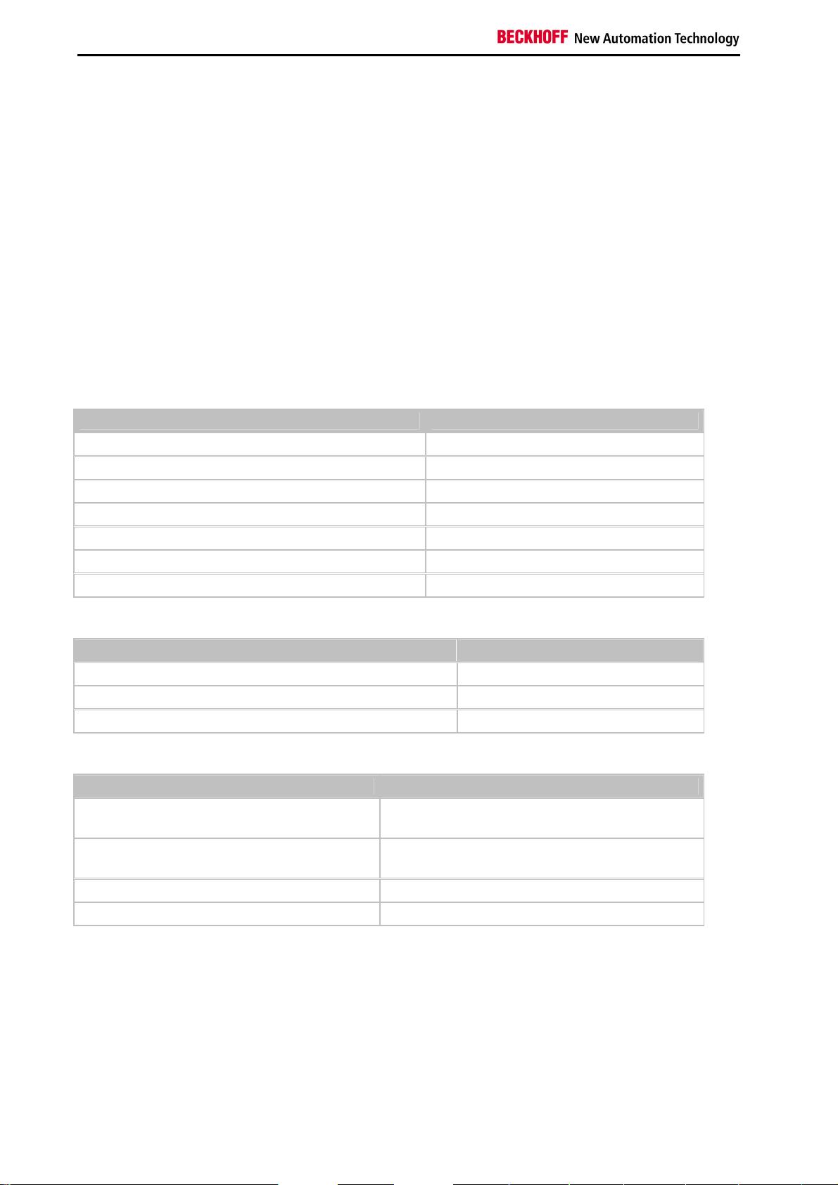
Notes on the Documentation
8. Appendix
General Operating Conditions
The following conditions must be observed if the fieldbus components are to function without error.
Environmental conditions
Operation
The components may not be used without additional protection in the following locations:
•
in difficult environments, such as where there are corrosive vapors or gases, or high dust levels
•
in the presence of high levels of ionizing radiation
Condition Permissible range
Permissible ambient temperature range during operation 0°C ... +55°C
Permissible relative humidity during operation 95 %, no condensation
Installation position variable
Vibration resistance conforms to EN 60068-2-6
Shock resistance conforms to EN 60068-2-27, EN 60068-2-29
EMC resistance burst conforms to EN 61000-6-2
ESD emission conforms to EN 61000-6-4
Transport and storage
Condition Permissible range
Permissible ambient temperature range during storage -25 °C ... +85°C
Permissible relative humidity 95 %, no condensation
Free fall up to 1 m in the original packaging
Protection classes and types
Condition Permissible range
Protection class in accordance with IEC 536 (VDE
0106, Part 1)
Protection class according to IEC 529 IP20 (protection against contact with a standard test
Protection against foreign objects Less than 12 mm in diameter
Protection against water No protection
A protective conductor connection to the mounting rail
is necessary!
finger)
88 Fieldbus Components
Page 91
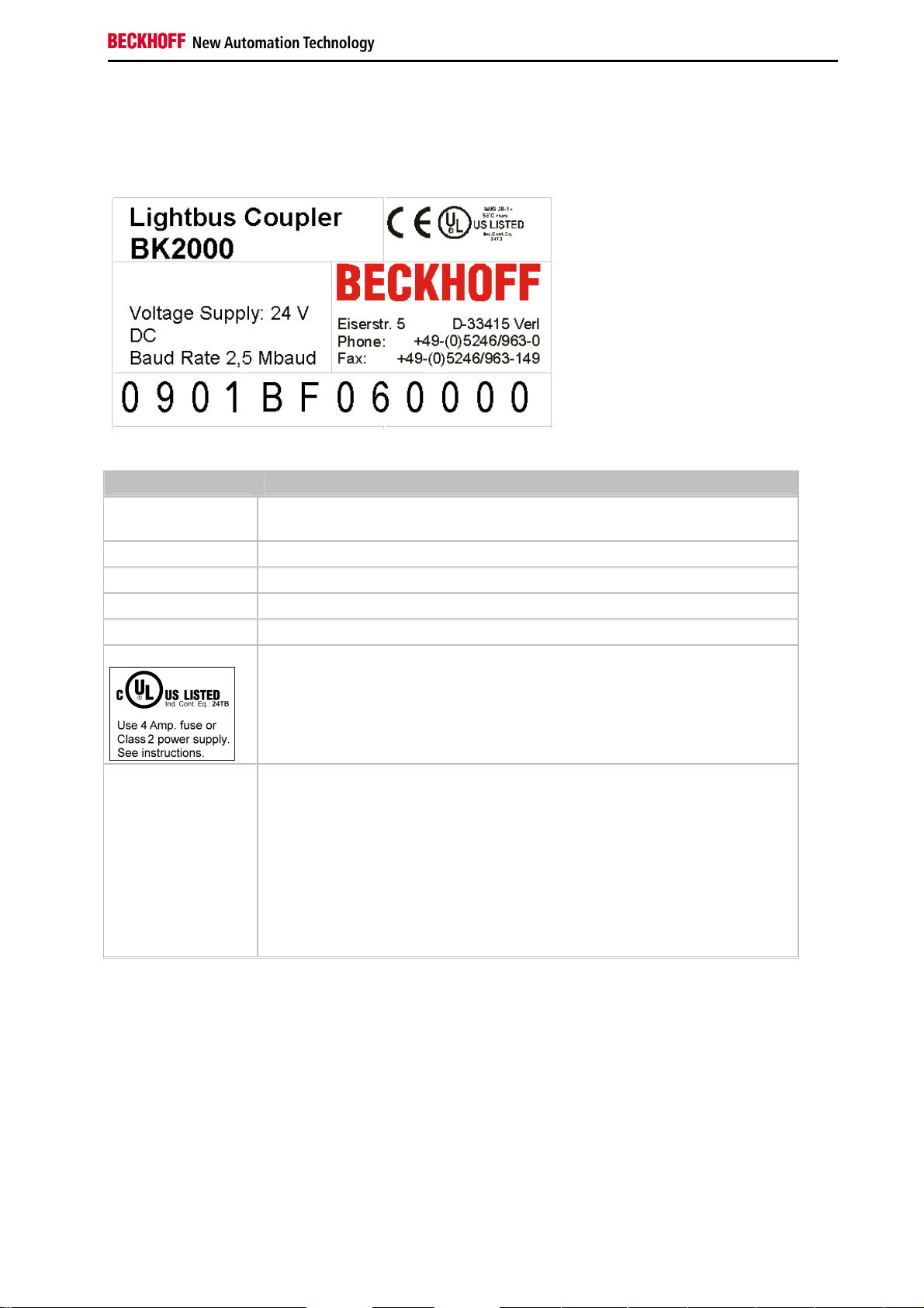
Notes on the Documentation
Component identification
Every supplied component includes an adhesive label providing information about the product's approvals. For
example, on the BK2000:
The following information is printed on the label:
Printed item In this particular example:
Precise product
identification
Supply voltage Us 24 VDC (To meet the UL requirements use 4 A fuse or class 2 power supply!)
Data transfer rate 2.5 MBaud
manufacturer Beckhoff Automation GmbH
CE mark Conformity mark
UL mark
Lightbus Coupler BK2000
Mark for UL approval. UL stands for the Underwriters Laboratories Inc., the leading
certification organization for North America, based in the USA.
C = Canada, US = USA,
UL File Number: E172151
Production
identification
From left to right, this sequence of characters indicates the production week (2
characters), the production year (2 characters), the software version (2 characters)
and hardware version (2 characters), along with any special indications (4
characters).
This case therefore is a BK2000
- produced in the 9th calendar week
- of the year 2001
- containing the BF firmware version
- and using the 6th hardware version
- with no special indications
Fieldbus Components 89
Page 92

Approvals
Approvals
UL E172151
Conformity mark
CE
Protection class
IP20 in accordance with EN60529
90 Fieldbus Components
Page 93

Conformity mark
Bibliography
German books
PROFIBUS
•
PROFIBUS-DP/DPV1
Grundlagen, Tipps und Tricks für Anwender (Principles, Tips for Users)
by Manfred Popp
ISBN: 3778527819
General fieldbus technology
•
Gerhard Gruhler (Pub.): Feldbusse und Geräte-Kommunikationssysteme (Fieldbus and Device Communication Systems)
Praktisches Know-How mit Vergleichsmöglichkeiten (Practical Know-how with Comparative Resources)
Franzis Verlag, 2001
244 pages
ISBN 3-7723-5745-8
English books
(in preparation)
PROFIBUS-DP standards
•
IEC 61158 and IEC 61784
•
DIN 19245, Part 3
•
Euronorm EN 50 170
Web sites
•
http://www.profibus.com
Fieldbus Components 91
Page 94

Conformity mark
List of Abbreviations
DP
Distributed Peripherals. PROFIBUS protocol for fast cyclic data exchange
FMS
Fieldbus Message Specification. The PROFIBUS transmission protocol
Freeze mode
This command makes the slave freeze its inputs
GSD file
Basic device file (in German)
GSE file
Basic device file (in English)
IP20, IP65, IP66, IP67
Protection class (contact, water, dust)
K-Bus
Terminal bus - internal bus for communication between the coupler and Bus Terminals
PNO
PROFIBUS User Organisation
Repeater
Provides signal conditioning, connecting individual bus segments
PLC
Programmable logic controller
Sync mode
This command makes the slave hold its outputs unchanged until it receives the Sync telegram.
92 Fieldbus Components
Page 95

Conformity mark
Support and Service
Beckhoff and their partners around the world offer comprehensive support and service, making available fast and
competent assistance with all questions related to Beckhoff products and system solutions.
Beckhoff Support
Support offers you comprehensive technical assistance, helping you no only with the application of individual
Beckhoff products, but also with other, wide-ranging services:
•
world-wide support
•
design, programming and commissioning of complex automation systems
•
and extensive training program for Beckhoff system components
Hotline: +49(0)5246/963-157
Fax: +49(0)5246/963-9157
e-mail: support@beckhoff.com
Beckhoff Service
The Beckhoff Service Center supports you in all matters of after-sales service:
•
on-site service
•
repair service
•
spare parts service
•
hotline service
Hotline: +49(0)5246/963-460
Fax: +49(0)5246/963-479
e-mail: service@beckhoff.com
You will find further support and service addresses on our Internet pages under http://www.beckhoff.com.
Beckhoff Headquarters
Beckhoff Automation GmbH
Eiserstr. 5
33415 Verl
Germany
Phone: +49(0)5246/963-0
Fax: +49(0)5246/963-198
e-mail: info@beckhoff.com
The addresses of Beckhoff's branch offices and representatives round the world can be found on her internet pages:
http://www.beckhoff.com
You will also find further documentation for Beckhoff components there.
Fieldbus Components 93
 Loading...