


CASCADE PRO 7941

Installation Guide
2
Installation Guide
Contents
Prior to installation . . . . . . . . . . . . . . . . . . . . . . . . . . . . . . . . . . . . . . . . . . . . . . . . . . . . . . . . . . . . .2
Symbols used in the installation guide . . . . . . . . . . . . . . . . . . . . . . . . . . . . . . . . . . . . . . . . . . . . . .2
Safety instructions . . . . . . . . . . . . . . . . . . . . . . . . . . . . . . . . . . . . . . . . . . . . . . . . . . . . . . . . . . . . .3
Installation instructions . . . . . . . . . . . . . . . . . . . . . . . . . . . . . . . . . . . . . . . . . . . . . . . . . . . . . . . . .4
Connection diagram for the navigation system . . . . . . . . . . . . . . . . . . . . . . . . . . . . . . . . . . . . . . . 5
Installation of the GPS antenna . . . . . . . . . . . . . . . . . . . . . . . . . . . . . . . . . . . . . . . . . . . . . . . . . . . 6
Connecting a GSM antenna . . . . . . . . . . . . . . . . . . . . . . . . . . . . . . . . . . . . . . . . . . . . . . . . . . . . . . 8
Installation of the microphone . . . . . . . . . . . . . . . . . . . . . . . . . . . . . . . . . . . . . . . . . . . . . . . . . . . . 9
Connection of the reverse signal . . . . . . . . . . . . . . . . . . . . . . . . . . . . . . . . . . . . . . . . . . . . . . . . . .12
Connection of the speed signal (GAL) from the speedometer/ tachometer . . . . . . . . . . . . . . . . . . 13
Installation/ Removal of the Cascade . . . . . . . . . . . . . . . . . . . . . . . . . . . . . . . . . . . . . . . . . . . . . . .16
Commissioning and calibration . . . . . . . . . . . . . . . . . . . . . . . . . . . . . . . . . . . . . . . . . . . . . . . . . . . 17
Service mode . . . . . . . . . . . . . . . . . . . . . . . . . . . . . . . . . . . . . . . . . . . . . . . . . . . . . . . . . . . . . . . . .20
Connections . . . . . . . . . . . . . . . . . . . . . . . . . . . . . . . . . . . . . . . . . . . . . . . . . . . . . . . . . . . . . . . . . . 24
Prior to installation
Before starting installation, please read this installation guide carefully. In particular, please pay attention to the safety and
installation instructions.
Symbols used in the installation guide
G denotes instructions which are important for your safety and the safety of others.
denotes instructions which are important for the installation and function of the unit.

Installation Guide
3
Safety instructions
G Incorrect installation
Incorrect installation may result in damage to the unit or to the vehicle. Specialist knowledge and skills are required to
install the unit and its components. We strongly recommend that you have the unit installed by a specialist workshop.
G Risk of injury
Installing the components incorrectly may lead to injuries in the event of a road traffic accident or render safety
devices ineffective. Please refer to the instructions provided by the vehicle manufacturer.
G Damage to the airbag
Installing the components in the wrong location may damage the airbag or impair its operation. Do not install the
components within the operating range of the airbag.
G Risk of injury due to loose connection
Connect the components so that they cannot come loose in the event of a collision or sudden braking.
Installation Guide
4
Installation instructions
Damage due to polarity reversal or short-circuit
Incorrect cable connections and short-circuits can seriously damage the unit.
Disconnect the vehicle battery before installing the unit.
In order to avoid short-circuits and malfunctions, install the cables so that they cannot be pinched, kinked, chafed
or detached.
Before installation, park the vehicle in a safe and level place and remove the ignition key.
In order to avoid malfunctions, it is absolutely essential to observe the relevant cable cross-section when using
branch connections/cable connectors.
In order to avoid short-circuits and any associated risk of fire, cables which have to be cut must be properly
insulated.
Installation Guide
5
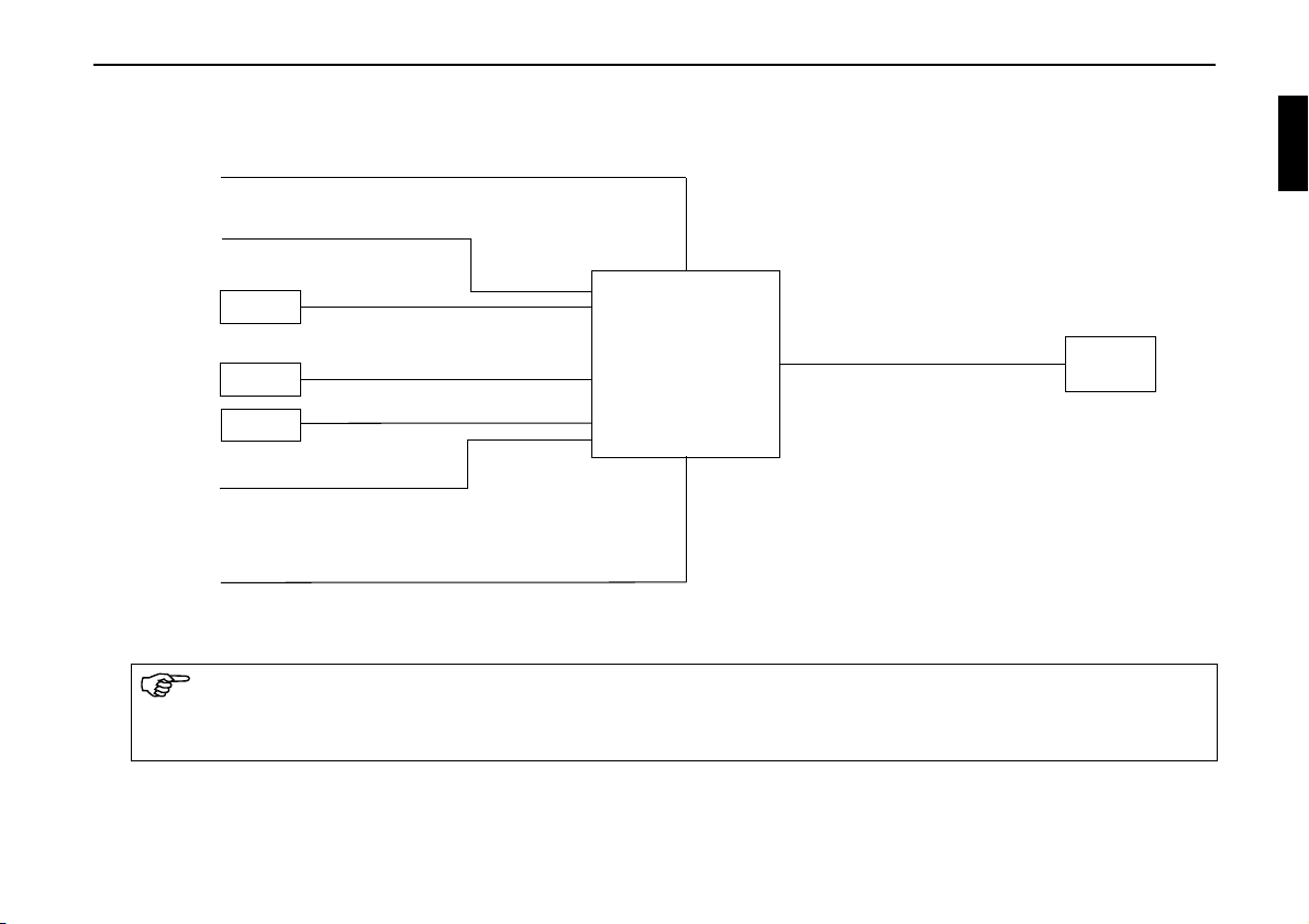
Connection diagram for the navigation system
Connection options are described in detail on Page 24.
The connection for a GSM antenna is only provided in devices with a built-in telephone.
The power supply must be protected separately by its own fuses.
Radio aerial
Speedometer/speedometer cable signal
GPS antenna
Power supply
Reverse signal
Navigation unit
Sound system/
loudspeaker
Microphone
GSM antenn

Installation Guide
6
Installation of the GPS antenna
Possible installation positions
• Outside the vehicle
a. Attach the antenna to a flat, pre-washed metal surface.
b. Then guide the antenna cable into the vehicle interior.
G Risk of injury
People with pacemakers should avoid proximity to the magnetic antenna and should not carry the antenna on their
person, as this may affect the function of the pacemaker.
Keep the magnetic antenna away from data storage media (disks, credit cards, magnetic cards etc.) and electronic
and precision engineering equipment, as this may cause data to be deleted.
Do not use the antenna in areas at risk of explosion.
The antenna is to be affixed in such a manner that it cannot detach in the event of a collision or sudden braking.
G Risk of injury
The maximum vehicle speed for the antenna if magnetically attached is 180 km/h. The antenna must be removed or
specially secured at higher speeds.
The antenna is not suitable for car-wash facilities.

Installation Guide
7
• Inside the vehicle
The GPS antenna is not suitable for installation in vehicles with anti-glare windows (metalised thermo-glass or
metal foil (can be seen on the window label - SIGLA SOL, SIGLA CHROM, SIGLA, KOOL-OF, SUNGATE,
etc.) and vehicles with fine-meshed heating wires in the windows.
Information on installation position
When selecting the installation position, ensure that the antenna has a clear view in all directions, and that it is
not covered by the windscreen wipers. Obstructions caused by the bonnet, window crossbeams and roof should
be avoided as far as possible.
Concealed installation beneath the vehicle console is not permitted.
Installation on the vehicle side windows is not permissible.
The antenna cable should not run parallel to other cables in the vehicle.
The antenna cable should be routed via the shortest distance from the navigation system to the antenna. The
excess cable should be attached directly below the antenna.
Installation Guide
8
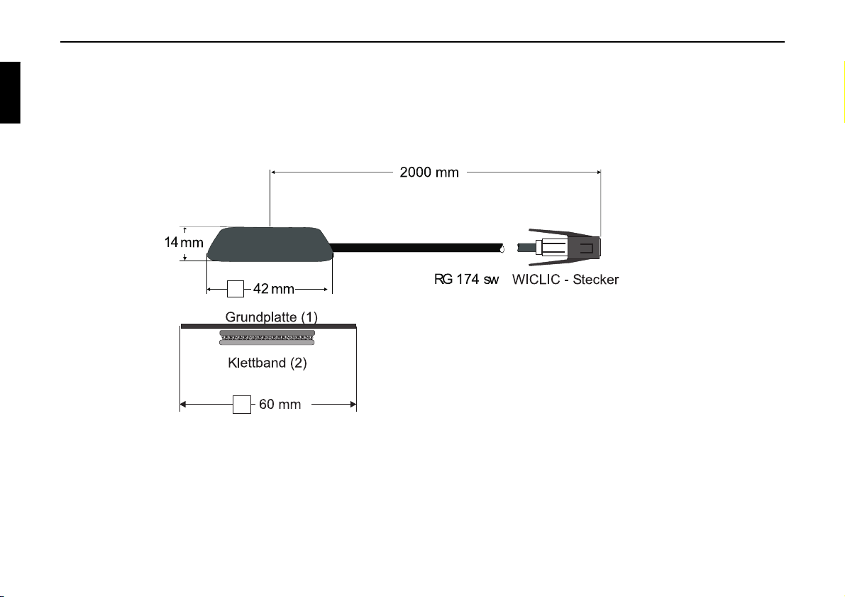
a. Secure the antenna to the base plate (1) with magnets.
b. Remove protective strip from top of adhesive tape (2) and stick to the centre of the base plate underside.
c. Remove protective strip from bottom of adhesive tape (2) and stick the antenna and base plate onto the vehicle
console beneath the windscreen at the installation position.
Connecting a GSM antenna
The connection of a GSM antenna is only necessary or possible for devices with a built-in telephone module.
As a GSM telephone antenna is already installed in many vehicles, an adapter is supplied with the device (device connection on
an FME connector). Connect the adapter lead to the corresponding socket on the rear of the device. You can then connect to the
adapter lead either a commercially available telephone antenna or an antenna that is already installed in the vehicle. If the con-
nections do not fit, you will need to use appropriate adapters.
 Loading...