


ACU6100-1-(020)
Becker ACU6100-1-(020), ACU6100-2-(020), ACU6100-1-(120), ACU6100-2-(120), ACU6100-1-(220) Installation And Operation Manual
...
Installation and Operation
Manual DV 64440.03
Issue 1 September 2005
Change 2 October 2008
Becker FlugfunkwerkGmbH · Baden Airpark· 77836 Rheinmünster · Germany
Telephone +49 (0) 7229 / 305-0 · Fax +49(0) 7229 / 305-217
http://www.becker-avionics.com · e-mail: info@becker-avionics.de
Audio Control Unit
ACU6100-x-(xxx)
FIRST ISSUE AND CHANGES
Issue . . . . . 1 . . . . . September 2005
Change . . . .1 . . . . January 2008
Change . . . .2 . . . . October 2008
LIST OF EFFECTIVE PAGES
Page No.: Date : Page No.: Date :
Title
ISO 9001
1 -I - 1-II
1-1 - 1-4
1-5
1-6 - 1-8
1-9
1-10
2-I - 2-II
2-1 - 2-10
3-I - 3-II
3-1
3-2
3-3 - 3-12
3-13
3-14 - 18
10/2008
09/2005
09/2005
09/2005
10/2008
09/2005
01/2008
09/2005
09/2005
09/2005
09/2005
09/2005
10/2008
09/2005
10/2008
09/2005
DV64440.03/ArticleNumber0589.845-071
© 2005byBeckerFlugfunkwerk GmbH/Allrightsreserved

Qualitätszertifikat
Sehr geehrter Kunde,
Sie haben sich für den Kauf eines Becker -
Produktes entschieden. Hiermit erhalten Sie ein
nach modernsten Fertigungsmethoden hergestelltes Produkt. Es wurde nach den Regeln
unseres Qualitätsmanagementsystems
entwickelt, gefertigt und geprüft.
Certificate of qualitiy
Dear Customer,
you have decided to buy a Becker product. You
are assured of receiving a product that is
manufactured using the most modern methods
available. This product was developed,
manufactured and tested in compliance with our
quality management system standards.
ISO 9001
Certified Quality System
Das Becker- Qualitätsmanagementsystem ist zertifiziert nach:
The Becker quality management system is certified according to:
DIN EN ISO 9001 CERT Reg. - Nr. 12 100 20988
Zulassungen und Genehmigungen:
Licenses and Approvals:
BWB-1921Y-B07/04/01 Zulassung als Luftfahrtbetrieb für Luftfahrtgerät der Bundeswehr
Manufactures license for aviation equipment to the German armed forces
DE.21G.0075 Genehmigung als Herstellerbetrieb nach EASA Teil 21
Hauptabschnitt A, Abschnitt G
Production Organization Approval, EASA Part 21 Section A, Subpart G
DE.145.0166 Genehmigung als Instandhaltungsbetrieb nach EASA-145
Maintenance Organization Approval EASA-145


TAB LE OF CON TENTS
Sec ti on 1 GE NE RAL IN FOR MA TI ON Page
1.1 In tro duc ti on 1-1
1.2 Application 1-1
1.3 Ge ne ral des crip ti on 1-2
1.3.1 Me cha ni cal des crip ti on 1-2
1.3.2 Elec tri cal des crip ti on 1-2
1.3.2.1 Ge ne ral functions 1-2
1.4 Iden ti fi ca ti on of ar ti cle 1-5
1.4.1 Ty pes of Auio Con trol Unit 1-5
1.5 Tech ni cal data 1-6
1.5.1 Po wer supp ly 1-6
1.5.2 Con trol data trans fer ACU-REU 1-6
1.5.3 Me cha ni cal data 1-6
1.5.4 Unit con nec tors 1-7
1.5.5 En vi ron men tal con di tions 1-7
1.6 Soft wa re 1-7
1.7 Approvals 1-8
1.8 En vi ron men tal qua li fi ca ti on (EU RO CAE/RTCA ED-14D/DO-160D) 1-8
1.9 Sco pe of de li very 1-9
1.10 Ac ces so ries (not contained in the sco pe of de li very) 1-9
ACU6100
DV 64440.03/.04 Is sue 1 Sept./ 2005 Page 1-I

BLANK
ACU6100
Page 1-II DV 64440.03/.04 Is sue 1 Sept./ 2005
Sec ti on 1 GE NE RAL IN FOR MA TI ON
1.1 In tro duc ti on
The BECKER ACU6100-X-(XXX) Au dio Con trol Unit is des cri bed in the ”In stal la ti on and Ope ra ti on”
DV 64440.03 and “Mai nten an ce and Re pair” DV 64440.04 ma nu als.
The ma nu als con tain the fol lo wing sections :
Sec ti on DV 64440.03 DV 64440.04
1 Ge ne ral In for ma ti on X X
2 In stal la ti on X X
3 Ope ra ti on X X
4 Theo ry of Ope ra ti on X
5 Main ten an ce and Re pair X
6 IIlu stra ted Parts List X
7 Mo di fi ca ti on and Chan ges X
8 Cir cuit Dia grams X
9 List of the used Ab bre via tions X
1.2 Ap pli ca ti on
The Au dio Con trol Unit is part of the Di gi tal Voi ce Com mu ni ca ti on Sys tem DVCS 6100 and pro vi ded for
in stal la ti on in an air craft. It ser ves for the con trol of REU6100 Remo te Elec tro nic Unit. Ma xi mum six
Au dio Con trol Units can be con nec ted to the Remo te Elec tro nic Unit. The Au dio Con trol Unit is iden ti cal
for each in stal la ti on lo ca ti on (ca bin, cock pit, etc.).
ACU6100
DV 64440.03/.04 Issue 1 Sept./2005 Page 1-1

1.3 Ge ne ral des crip ti on
1.3.1 Mechanical description
The Audio Con trol Unit is de sig ned for in stal la ti on in the ope ra tor con so le of air craft. The di men sions
cor re spond to the ARINC 601 stan dard for con trol units. In stal la ti on is by me ans of four DZUS fa ste ners.
The Au dio Con trol Unit con sists of the fol lo wing elec tri cal as sem blies re spec ti ve ly cir cuit bo ards :
q Il lu mi na ti on board
q Ro ta ry board
q 2 x Vo lu me board
q Pro ces sor board
q Con nec tor Board
1.3.2 Elec tri cal des crip ti on
1.3.2.1 Ge ne ral Functions
The Au dio Con trol Unit shall com pri se a ma xi mum of six con trol pa nels to pro vi de the fol lo wing
functions in de pen dent ly:
q Dri ving of up to 8 trans cei vers or 7 trans cei vers plus one pub lic ad dress (PA) am pli fier
q In di ca ti on of trans mis si on via sta tus lights
q Mo ni to ring of up to 8 trans cei vers with a ca pa bi li ty of in di vi du al vo lu me con trol
q Mo ni to ring of up to 8 re cei vers with a ca pa bi li ty of in di vi du al vo lu me con trol
q Mo ni to ring of up to 6 fi xed in puts
q Mo ni to ring of up to 10 in ter nal ly ge ne ra ted sig nal to nes. 8 to nes can be ac ti vat ed by
di scre te con trol li nes from ex ter nal (au ral alert to nes).
q Main vo lu me con trol
q Air craft in ter com mu ni ca ti on in eit her VOX or PTT-controlled mode
q 2 in ter com cir cuits to se pa ra te cock pit and ca bin com mu ni ca ti on
q Op ti cal call in di ca ti on for in ter com re quest plus acous ti cal call alert for com bi ning or
se pa ra ting the dif fe rent in ter com cir cuits as sig ned to the in di vi du al con trol unit
q Ca pa bi li ty for dri ving and con trol ling a cock pit or ca bin spea ker de pen ding on the
con trol unit
q Pro vi si on for in ter com am pli fier con nec ti on
q Cock pit voi ce re cor der con nec ti on ca pa bi li ties se pa ra ted for pi lot an co pi lot
ACU6100
Page 1-2 DV 64440.03/.04 Issue 1 Sept./2005

q P-BIT, I-BIT, C-BIT functio na li ty with op ti cal in di ca ti on of test sta tus/re sult
q Fall-back to Back-Up ope ra ti on upon fai lu re of po wer supp ly (ba ckup po wer supp ly
from air craft ne ces sa ry!); ma nu al ly Back-Up ope ra ti on in case or of de fec ti ve Au dio
Con trol Unit or part the re of
q Con fi gu ra ti on ca pa bi li ty for sys tem in te gra ti on or main ten an ce shops to con fi gu re
and adapt the sys tem to the in di vi du al air craft re qui re ments
The functio nal ins crip tions of key caps, ro ta ry switch, and in cre ment sen sor are fi nis hed in whi te trans lu cent cha rac ters. Il lu mi na ti on is com pa ti ble with com mon ly used night vi si on gog gles (NVG).
Every Au dio Con trol Unit has a mi cro con trol ler to pro cess switch and but ton ac ti vat ions as well as in di ca ti on sig nals. Con trol data is trans fer red via a dual re dun dant can bus in ter fa ce. SLA VE po si ti on (tog gle switch) and Back-up tog gle switch are not be rou ted through the in ter fa ce but must be hard-wi red
in or der to al low Back-up ope ra ti on, even if the unit had fai led.
Au dio Con trol Units are fac to ry con fi gu ra ble to dif fe rent ope ra ti on pro fi les, e.g. dis ab ling cer tain trans cei ver or re cei ver ac ces si bi li ty in the ca bin / pas sen ger area. Au dio Con trol Units may also be equip ped
with front pa nels im prin ted to cus to mer re quests.
All con trols and LED- in di ca tors of the Au dio Con trol Unit are lo ca ted on the ro ta ry board, pro ces sor
board and vo lu me boards :
Ro ta ry board:
The fol lo wing are moun ted on the ro ta ry board
q 1 ro ta ry switch, 10 po si tions, to pre se lect the ac ti ve trans cei ver as well as Pub lic Ad -
dress or In ter com mode. Also to se lect dual trans mis si on mode if pro vi ded (op ti on).
q 1 lockable switch.
q 1 PTT but ton ( tog gle switch).
Processor board:
The fol lo wing are moun ted on the processor board
q Dual po ten tio me ter to set the in di vi du al main vo lu me con trol (ou ter ro ta ry knob) and
to set the in di vi du al IC vo lu me con trol (in ner ro ta ry knob).
q VOX po ten tio me ter to set the in di vi du al VOX vo lu me le vel.
Vo lu me board (top)
The fol lo wing are moun ted on the vo lu me board (top).
8 moni to ring but tons to switch on /off trans cei ver monit oring and in du vi du al vo lu me con trol.
ACU6100
DV 64440.03/.04 Issue 1 Sept./2005 Page 1-3

Vo lu me board (bot tom)
The fol lo wing are moun ted on the vo lu me board (bot tom)
8 mo ni to ring but tons to switch on /off re cei ver mo no tring and in du vi du al vo lu me con trol.
Il lu mi na ti on board
The fol lo wing are moun ted on the íl lu mi na ti on board
q VOICE but ton with LED to switch on and off the ident fil ter (green LED: fil ter on, ident
fre quen cy 1020 Hz sup pres sed)
q TEST but ton with green LED to in itia te the I-BITE. By pres sing the test button an in -
ter nal self test pro ce du re is start ed. Af ter the test the fol lo wing re sults are shown:
Re sult ”GO” LED goes off
Re sult ”NOGO” LED flas hes for all con trol functions
q SPKR but ton with LED to switch on and off the cock pit spea ker (green LED: spea ker
on)
q ISOL /CALL with LED to con trol the in ter com functions bet ween cock pit and ca bin
Con nec tor board
The two unit con nec tors are fit ted on the con nec tor board.
ACU6100
Page 1-4 DV 64440.03/.04 Issue 1 Sept./2005
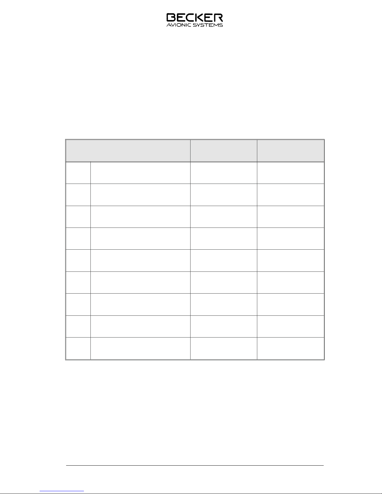
1.4 Identificationofarticle
1.4.1 TypesofAudioControlUnit
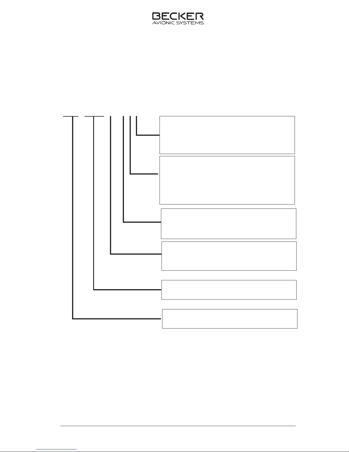
AudioControlUnit Part-numberACU6100-X-(XXX)
ACU6100-X-(XXX)
ACU6100
DV64440.03/.04Issue1change2Oct./2008 Page 1-5
Panelconfigurations
2 StandardPanelInlays
3 BlankPanelInlays
1 noNVGcompliant
2 NVGcompliant
Identificationnumber
AudioControlUnit
0= Panelcolor=black
1= Panelcolor=black(NVISfriendly)
2= Panelcolor=Grey
3= Panelcolor=Grey(NVIScompliant)
Illumination
0= Dimming=0.....28V(green)
1= Dimming=0.....5V(green)
2= Dimming=0.....28V(white)
3= Dimming=0.....5V(white)

1.5 Tech ni cal da ta
1.5.1 Po wer supp ly
Supp ly vol ta ge (Bus) I 27.5 V DC no mi nal
18.0 V DC emer gen cy
Supp ly vol ta ge (Bus) II 27.5 V DC nominal
18.0 V DC emergency
Back-Up vol ta ge (Bus) II 27.5 V DC no mi nal
18.0 V DC emer gen cy
Po wer con sump ti on ≤ 150 mA
Dim ming in put:
Dim con trol in put 1 max. 27.5 V DC
(pa nel il lu mi na ti on)
Dim con trol in put 2 max. 27.5 V DC
(LED bright ness)
1.5.2 Con trol data trans fer ACU-REU
In ter fa ce Dual CAN Bus (re du ndant)
Pro to col BFW specific
1.5.3 Me cha ni cal data
Width 145.8 mm
Heigth 75.8 mm
Depth 91.5 mm
Stan dard ARINC 601 8HE
Weight ≤ 800 g
Moun ting D-ZUS
ACU6100
Page 1-6 DV 64440.03/.04 Issue 1 Sept./2005

1.5.4 Unit con nec tors
Unit con nec tor P1 10-pol. series 851
Con trol bus- con nec tor P2 19-pol. series 851
- loc king de vi ce bayo net
1.5.5 En vi ron men tal con di tions
In put vol ta ge ran ge 22.0 to 30.3 V DC
- no mi nal in put vol ta ge 27.5 V DC
- emer gen cy in put vol ta ge 18.0 V DC
Ope ra ting tem pe ra tu re -40° C … +70° C
Sto ra ge tem pe ra tu re -55° C … +85° C
Al ti tu de max. 50.000 ft.
Hu mi di ty ra ting RTCA DO-160D, Cat. B,
Vi brat ion RTCA DO-160D, Cat. S,
vi brat ion cur ves M
RTCA DO-160D, Cat. U,
vibrat ion cur ves G
Ope ra ti onal shock 6 g in all directions
Crash sa fe ty 20 g shocks
20 g acceleration
Com pass safe dis tan ce mag ne tic effect no in flu en ce at a dis tan ce
of 30 cm, EU RO CAE /
RTCA ED-14D/DO-160D Class Z
1.6 Soft wa re
All data for ACU 6100 is sto red in the microcontroller. If the con trol ele ments are al te red, a data trans mis si on im me di ate ly ta kes pla ce to the Remo te Elec tro nic Unit. The soft wa re is clas sed as le vel C in
ac cor dan ce with the EU RO CAE / RTCA do cu ment ED12B / DO-178B.
ACU6100
DV 64440.03/.04 Issue 1 Sept./2005 Page 1-7
1.7 Appro vals
LBA-No.: TBD
ETSO ETSO - C50c Au dio Se lec tor
Pa nels and Am pli fiers
Soft wa re EU RO CAE/RTCA DO-178B/
ED-12B Le vel C
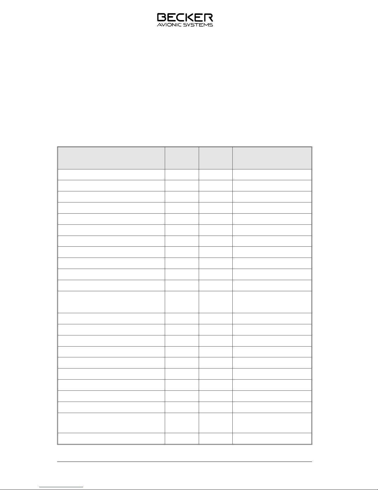
1.8 En vi ron men tal qua li fi ca ti on (EU RO CAE/RTCA ED-14D/DO-160D)
Cha rac te ris tic
ED-14D/DO-160D
Section Category Condition
Tem pe ra tu re / Altitude 4.0 D1
Low ground sur vi val temperature 4.5.1 D1 -55° C
Low ope ra ting tem pe rature 4.5.1 D1 -40° C
High ground sur vi val temperature 4.5.2 D1 +85° C
High short-time ope ra ting temperature 4.5.2 D1 +70° C
High ope ra ting temperature 4.5.3 D1 +55° C
In-Flight loss of cooling 4.5.4 Z no au xi lia ry coo ling required
Altitude 4.6.1 D1 50,000 ft.
Te mpe ra tu re variation 5.0 B 5° C per minute
Humidity 6.0 B 48 h at 65°C at 95% RH
Shock 7.0 B Test Type R in all 6 directions
Vibration 8.0 S
U
M
G
Ex plosi on proofness 9.0 X
Wa ter proofness 10.0 X
Fluids susceptibilities 11.0 X
Sand and dust 12.0 X
Fun gus resistance 13.0 X
Salt spray 14.0 X
Mag ne tic effect 15.0 Z less than 0.3 m
Po wer in put (DC) 16.0 B
Vol ta ge spike 17.0 A
Au dio fre quen cy con duc ted
susceptibility
18.0 A
In du ced sig nal sus cep ti bi li ty 19.0 A
ACU6100
Page 1-8 DV 64440.03/.04 Issue 1 Sept./2005
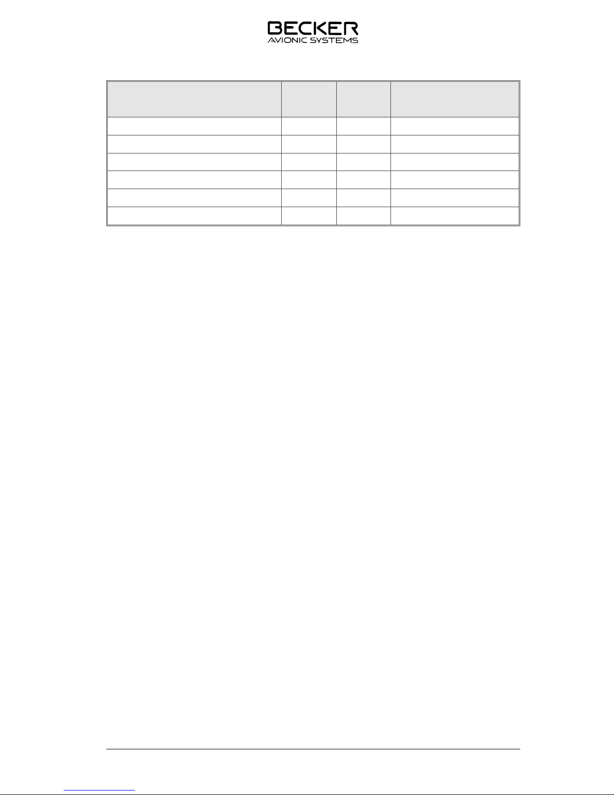
Cha rac te ris tic
ED-14D/DO-160D
Section Category Condition
Ra dio fre quen cy sus cep ti bi li ty 20.0 WR
Emis si on of RF 21.0 M
Light ning in du ced tran sient sus cep ti bi li ty 22.0 A3E3
Light ning di rect effects 23.0 X
Icing 24.0 X
Elec tro sta tic disch ar ge (ESD) 25.0 A
1.9 Sco pe of de li very
ACU6100-2-(120) Au dio Con trol Unit Ar ti cle-No.: 0585.319-921
ACU6100-2-(130) Au dio Con trol Unit Ar ti cle-No.: 0588.921-921
ACU6100-2-(230) Au dio Con trol Unit Ar ti cle-No.: 0597.678-921
1.10 Ac ces so ries (not con tai ned in the sco pe of de li vey)
Con nec tor Kit CK 5102-C Ar ti cle-No.: 0586.889-954
con sists of
10-pol. ca ble con nec tor, crimp Ar ti cle-No.: 0858.188-277
19-pol. ca ble con nec tor, crimp Ar ti cle-No.: 0794.279-277
CSW 6100 con fi gu ra ti on soft wa re set Ar ti cle-No.: 0589-047-919
con sists of
CAN - USB -Adap ter
CSW 6100 USB Don gle
In stal la ti on CD CSW 6100
Ma nu als:
In stal la ti on and Ope ra ti on DV 64440.03 Ar ti cle-No.: 0589.845.071
Main ten an ce and Re pair DV 64440.04 Ar ti cle-No.: 0589.853.071
In stal la ti on and Ope ra ti on Con fi gu ra ti on Ar ti cle-No.: 0590.428.071
Soft wa re CSW 6100 DV 6449.01
Ope ra ting instructions Ar ti cle No.: 0590.363-071
Blank
ACU6100
DV 64440.03/.04 Issue 1 Change 1 Jan./2008 Page 1-9
 Loading...