

Page 1

Cyclades® ACS 6000
Installation/Administration/User Guide
Page 2

FCC Warning Statement
The Cyclades ACS advanced console server has been tested and found to comply with the limits for Class A
digital devices, pursuant to Part 15 of the FCC rules. These limits are designed to provide reasonable protection
against harmful interference when the equipment is operated in a commercial environment.
This equipment generates, uses and can radiate radio frequency energy and, if not installed and used in
accordance with the Installation and Service Manual, may cause harmful interference to radio communications.
Operation of this equipment in a residential area is likely to cause harmful interference in which case the user is
required to correct the problem at his or her own expense.
Notice about FCC Compliance for All Cyclades ACS Advanced Console Server Models
To comply with FCC standards, the Cyclades ACS advanced console server requires the use of a shielded CAT
5 cable for the Ethernet interface. Notice that this cable is not supplied with either of the products and must be
provided by the customer.
Canadian DOC Notice
The Cyclades ACS advanced console server does not exceed the Class A limits for radio noise emissions from
digital apparatus set out in the Radio Interference Regulations of the Canadian Department of Communications.
L’Cyclades ACS advanced console server n’émete pas de bruits radioélectriques dépassant les limites
applicables aux appareils numériques de la classe A prescrites dans le règlement sur le brouillage radioélectrique
edicté par le Ministère des Communications du Canada.
Safety and EMC Approvals and Markings
FCC Class A (USA), CE Class A (EU), ICES-003 (Canada), VCCI (Japan), C-Tick (Australia, no internal modem),
A-Tick (Australia, with internal modem), UL 60950-1 (USA), cUL (Canada), EN-60950-1 (EU), CB
Page 3

Cyclades® ACS 6000 Advanced Console Server
Installation/Administration/User
Guide
Avocent, the Avocent logo, The Power of Being There, DSView and
Cyclades are registered trademarks of Avocent Corporation or its
affiliates in the US and other countries. All other marks are the property
of their respective owners.
© 2008 Avocent Cor poration. 590-767-501B
Page 4
Instructions
This symbol is intended to alert the user to the presence of important operating and maintenance (servicing)
instructions in the literature accompanying the appliance.
Dangerous Voltage
This symbol is intended to alert the user to the prese nce of unin sulated dangerous voltage within the product’s
enclosure that may be of sufficient magnitude to constitute a risk of electric shock to persons.
Power On
This symbol indicates the principal on/off switch is in the on position.
Power Off
This symbol indicates the principal on/off switch is in the off position.
Protective Grounding Terminal
This symbol indicates a terminal which must be connected to earth ground prior to making any other
connections to the equipment.
Page 5

TABLE OF CONTENTS
Table of Contents
List of Figures ................................................................................................................ vii
List of Tables................................................................................................................... ix
Chapter 1: Introduction ................................................................................................... 1
Features and Benefits ........................................................................................................................1
Web Manager..............................................................................................................................1
Access options.............................................................................................................................2
IPv4 and IPv6 support................................................................................................................2
Flexible users and groups.............................................. .............................................................3
Security.......................................................................................................................................3
Authentication.............................................................................................................................3
VPN based on IPSec with NAT traversal ...................................................................................3
Packet filtering............................................................................................................................4
SNMP..........................................................................................................................................4
Data logging, notifications, alarms and data buffering .............................................................4
Power management ........................... .........................................................................................4
Auto discovery ............................................................................................................................5
Configuration Example......................................................................................................................5
iii
Chapter 2: Installation ..................................................................................................... 7
Rack Mounting.................................................. .................................................................................7
Connecting the Hardware..................................................................................................................8
ACS console server connectors ..................................................................................................8
Device consoles or modems to serial ports................................................................................9
Power devices...........................................................................................................................11
Power Configuration .......................................................................................................................12
ACS 6000 Remote Console Server Configuration. ..........................................................................13
Making an Ethernet connection................................................................................................14
Making a direct connection......................................................................................................14
Accessing an ACS Console Server...................................................................................................15
Using the Web Manager...........................................................................................................15
Using Telnet/SSH......................................................................................................................15
Page 6

iv Cyclades ACS 6000 Advanced Console Server Installation/Administration/User Guide
Pluggable Devices Installation and Configuration .........................................................................17
Chapter 3: Web Manager Overview.............................................................................. 19
First Time Configuration.................................................................................................................19
Web Manager Overview for Administrators....................................................................................22
Web Manager Overview for Regular Users ....................................................................................25
Chapter 4: Using the Web Manager.............................................................................. 27
Global Settings.................................................................................................................................27
Sessions.....................................................................................................................................27
Sensors......................................................................................................................................27
Data buffering...........................................................................................................................28
Network Configuration ....................................................................................................................28
IPv6 options..............................................................................................................................28
Devices options.........................................................................................................................29
Bonding options........................................................................................................................30
IPv4 and IPv6 static routes options................................................................. .........................30
DNS options..............................................................................................................................31
Host options..............................................................................................................................31
Ports Configuration.........................................................................................................................32
Physical Ports....................................... ....................................................................................32
CAS Profile...............................................................................................................................33
Dial-In Profile ..........................................................................................................................36
Power Profile............................................................................................................................37
Pluggable Devices ...................... .....................................................................................................38
Security Configuration......................................................................................................... ............39
Authentication..................................................................................................................................41
Appliance authentication..........................................................................................................42
Authentication servers............................................. .................................................................42
Users Accounts and User Groups....................................................................................................44
Users accounts..........................................................................................................................44
User groups ......................................................................... .....................................................45
Syslog...............................................................................................................................................50
Event Notifications...........................................................................................................................50
Event Notifications - Settings ...................................................................................................51
Event Notifications - Events.................................. ...................................................... ..............52
Page 7

Table of Contents v
Firewall Configuration....................................................................................................................52
IPSec(VPN)......................................................................................................................................55
SNMP Configuration .......................................................................................................................56
Date and Time..................................................................................................................................57
Boot Configuration ..........................................................................................................................58
Online Help......................................................................................................................................59
Power Management.......................................... ...............................................................................59
Settings .....................................................................................................................................60
Management .............................................................................................................................61
Outlet Groups ...........................................................................................................................61
Power configuration.................................................................................................................62
Configuring a port for a connected PDU.................................................................................62
Monitoring .......................................................................................................................................66
Active Sessions.................................................................................................................................67
Appendices..................................................................................................................... 69
Appendix A: Techical Specifications ...............................................................................................69
Appendix B: Safety, Regulatory and Compliance Information........................................................71
Appendix C: Technical Support.......................................................................................................75
Page 8

vi Cyclades ACS 6000 Advanced Console Server Installation/Administrati on/User Guide
Page 9

LIST OF FIGURES
List of Figures
Figure 1.1: Typical ACS 6000 Advanced Console Server Configuration .........................................5
Figure 2.1: Bracket Connections for Front Mount Configuration....................................................7
Figure 2.2: Front of the Console Server with PC Card Slots and LEDs (ACS 6032 Console
Server Shown) .................................................................................................................................. 8
Figure 2.3: Rear of the Console Server (ACS 6032 Console Server Shown)....................................9
Figure 2.4: Example: Daisy-chained Cyclades PDUs....................................................................11
Figure 2.5: DC Power Connection Terminal Block........................................................................13
Figure 3.1: Administrator Web Manager Screen............................................................................22
Figure 3.2: Web Manager Regular User Screen.............................................................................25
vii
Page 10

viii Cyclades ACS 6000 Advanced Console Server Installation/Administration/User Guide
Page 11

LIST OF TABLES
List of Tables
Table 1.1: Typical ACS 6000 Advanced Console Server Configuration Descriptions .....................5
Table 2.1: Connectors on the Console Server Front .........................................................................8
Table 2.2: LEDs on the Console Server Front ..................................................................................8
Table 2.3: Connectors on the Console Server Rear ........................... ...............................................9
Table 2.4: Cyclades Serial Port Pinout...........................................................................................10
Table 2.5: Cisco Serial Port Pinout.................................................................................................10
Table 2.6: DC Power Connection Details.......................................................................................13
Table 3.1: Web Manager Screen Areas................................... ........................................................22
Table 3.2: Web Manager Options for Administrators.....................................................................23
Table 3.3: Web Manager Regular Users Screen Functional Areas ................................................25
Table 3.4: Web Manager Options for Regular Users......................................................................25
Table 4.1: CAS Profile Options....................................................................................................... 33
ix
Table 4.2: Security Profile Services, SSH, and HTTP/HTTPS Definitions .....................................40
Table 4.3: Event Notifications - Settings Screen Description .........................................................51
Table 4.4: Firewall Configuration - TCP and UDP Options Fields...............................................53
Table 4.5: Field and Menu Options for Configuring IPSec(VPN)..................................................5 5
Table 4.6: Monitoring Screens ........................................................................................................66
Table A.1: Technical Specifications for the ACS 6000 Console Server Hardware.........................69
Page 12

x Cyclades ACS 6000 Advanced Console Server Installation/Administration/User Guide
Page 13

CHAPTER
1
The Cyclades ACS 6000 advanced console server is a 1U appliance that serves as a single point for
access and administration of connected devices, such as target device consoles, modems and power
devices. ACS 6000 console servers support secure remote data center management and out-of-band
management of IT assets from any location worldwide.
NOTE: Unless noted, references to the ACS 6000 console server refer to all models in the 60XX series.
1
Introduction
ACS 6000 console servers provide secure local (console port) and remote (IP and dial-up) access.
The console servers run the Linux
and they can be upgraded from either an FTP or DSView
You can use the Web Manager, the Command Line Interface (CLI utility) or DSView 3
management software (version 3.5.1 and greater) to configure the ACS 6000 console server.
Multiple administrators can be logged into the console server at the same time.
Two PC card/slots support modem (V.92 and Wireless GSM/CDMA), Ethernet, fast Ethernet (fiber
optic), wireless LAN and storage PC cards (16 bit and 32 bit). One USB port supports modem
(V.92 and Wireless GSM/CDMA), storage devices and USB hubs. Two fast Ethernet ports support
connections to more than one network or configuration of Ethernet bonding (failover) for
redundancy and greater reliability. For dial-in and secure dial-back with Point-to-Point Protocol
(PPP), optional internal modems can be factory installed, or you can use external modems or
wireless modem CardBus devices.
Features and Benefits
Web Manager
Users and administrators perform most tasks through the Web Manager (accessed with HTTP or
HTTPS). The Web Manager runs in any supported browser (such as Netscape
Explorer
console server.
The administrator can use the Web Manager to create user accounts, authorize groups and
configure security and ports. An authorized user can access connected devices through the Web
®
, Firefox® or Mozilla®) on any supported computer that has network access to the
®
operating system with a persistent file system in Flash memory,
®
software server.
®
, Internet
Page 14

2 Cyclades ACS 6000 Advanced Console Server Installation/Administration/User Guide
Manager to troubleshoot, maintain, cycle power, reboot connected devices and change the user
password. For more information on the Web Manager, see Chapters 3 and 4.
Access options
Secure access is available through the following local (analog console port) and remote (digital IP
and dial-up) options:
• LAN/WAN IP network connection.
• Dial-up either to a factory-configured internal modem (optional), to a modem connected either
to a serial port or the AUX port (which is only possible when an internal modem is not
installed), or to a PC phone card (modem, GSM or CDMA) installed in one of the PC card
slots or in the USB port.
• T arget device connection. If a serial port is connected to the console of a device, an authorized
user can make a Telnet, SSH v1 or SSH v2 connection to the device console through the Web
Manager. An authorized user can also use a Telnet or SSH client to make a connection directly
to the console of a target device. (For Telnet or SSH to be used for target device connections,
the Telnet or SSH service must be configured in the security profile that is in effect.)
• ACS 6000 console server console connection. An administrator can log in either from a local
terminal or from a computer with a terminal emulation program that is connected to the
console port and can use the CLI utility. The CLI utility prompt (--|- cli>) displays at login.
More than one administrator (root or admin or a user in the administrator group) can log into the
console server and have an active CLI or Web Manager session. All sessions receive a warning
message when the configuration is changed by another administrator or by the system: The
appliance configuration has been altered from outside of your session. Upon receipt of this
message, each administrator needs to verify that changes made during the session were saved.
NOTE: If cron jobs are run by automated scripts, a root or admin user login can cause the cron jobs to fail.
IPv4 and IPv6 support
The ACS 6000 console server supports dual stack IPv4 and IPv6 protocols. The administrator can
use the Web Manager or CLI to configure support for IPv4 addresses only or for both IPv4 and
IPv6 addresses. The following list describes the IPv6 support provided in the console server:
• DHCP
• Dial-in sessions (PPP links)
• DSView software integration
• eth0 and eth1 Ethernet interfaces
• Firewall (IP tables)
• Linux kernel
• Remote authentication: Radius, Tacacs+, LDAP and Kerberos servers
•SNMP
Page 15

• SSH and Telnet access
• Syslog server
NOTE: Remote authentication NIS and IPSec are not supported with IPv6.
Flexible users and groups
An account can be defined for each user on the console server or on an authentication server. The
admin and root users have accounts by default, and either can add and configure other user
accounts. Access to ports can be optionally restricted, based on authorizations that an administrator
can assign to custom user groups. Groups can be authorized to manage power while connected to
devices. For more information, see
Security
Security profiles determine which network services are enabled on the console server. Using the
Web Manager or the CLI, you can configure automatic detection of PC cards and USB devices or
RPC. You can either allow all users to access enabled ports or allow the configuration of group
authorizations to restrict access. You can also select a security profile, which defines which
services (FTP, ICMP, IPSec and Telnet) are enabled and SSH and HTTP/HTTPS access. The
administrator can select either a preconfigured security profile or create a custom profile. For more
information, see
Security Configuration on page 39.
Chapter 1: Introduction 3
Users Accounts and User Groups on page 44.
Authentication
Authentication can be performed locally, with One Time Passwords (OTP), or on a remote
Kerberos, LDAP, NIS, Radius or TACACS+ authentication server. If the ACS 6000 console server
is managed by a DSView 3 server, DSView authentication is also supported. The console server
also supports remote group authorizations for the LDAP, Radius and TACACS+ authentication
methods. Fallback mechanisms are also available.
An administrator can configure authentication using the CLI utility and the Web Manager. Any
authentication method that is configured for the console server or th e ports is used for
authentication of any user who attempts to log in through Telnet, SSH or the Web Manager. For
more information, see
Authentication on page 41.
VPN based on IPSec with NAT traversal
If IPSec is enabled in the selected security profile, an administrator can use the VPN feature to
enable secure connections. IPSec encryption with optional NAT traversal (which is configured by
default) creates a secure tunnel for dedicated communications between the console server and other
computers that have IPSec installed, such as routers, firewall machines, application servers and
end-user machines. ESP and AH authentication protocols, RSA Public Keys and Shared Secret
are
supported. For more information, see IPSec(VPN) on page 55.
Page 16

4 Cyclades ACS 6000 Advanced Console Server Installation/Administration/User Guide
Packet filtering
An administrator can configure the device to filter packets like a firewall. Packet filtering is
controlled by chains. A chain is a named profile configured with one or more rules that define both
a set of characteristics to look for in a packet and what to do with any packet that has the defined
characteristics. The console server filter table contains a number of built-in chains that cannot be
deleted; all input and output packets and packets to be forwarded are accepted. The policies for how
to handle built-in chains can be modified.
To configure packet filtering, an administrator can add a new chain and specify rules for that chain,
add new rules to existing chains and edit a built-in chain or delete the built-in chain rules.
SNMP
If SNMP is enabled in the selected security profile, an administrator can configure the Simple
Network Management Protocol (SNMP) agent that resides on the console server to send
notifications about significant events or traps to an SNMP management application.
The console server SNMP agent supports SNMP v1/v2 and v3, MIB-II and Enterprise MIB. For
more information, see
NOTE: The text files with the Enterprise MIB (ACS6000-MIB.asn) and the TRAP MIB (ACS6000-TRAP-MIB.asn)
are available in the appliance under the /usr/local/mibs directory.
SNMP Configuration on page 56.
Data logging, notifications, alarms and data buffering
An administrator can set up logging, notifications and alarms to alert administrators of problems
with email, SMS, SNMP trap or DSView 3 software notifications. The administrator can also
configure storage of data in data buffer files. Buffered data can be stored locally in the RAM disk
or on storage PC cards or a storage USB device, or remotely either on an NFS server or a syslog
server.
DSView 3 management software can also be used to store buffered data.
Local and remote data logging (NFS) includes support for rotations and for commands to search for
strings. Data logging when the console server is managed by DSView 3 management software
requires a license. Messages about the console server and connected servers or devices can also be
sent to syslog servers.
Power management
Connected power devices can be used for remote power management. The ACS 6000 console
server enables users who are authorized for power management to turn power on, turn power off
and reset devices that are plugged into a connected PDU. The power devices can be connected to
any serial port or to the AUX/Modem port (if an internal modem is not installed). For more
information, see
Power Management on page 59.
Page 17
Auto discovery
3
4
4
5
1
10
2
6
7
8
9
12
13
14
11
An administrator can enable auto discovery for a serial port. If the hostname of the connected target
device is successfully discovered, the hostname is shown instead of the serial port alias. This
feature can save time for administrators because they do not need to enter port aliases manually.
NOTE: If the console server is being managed through DSView 3 software, hostname discovery can be
configured through the DSView 3 software.
Default probe and answer strings used for auto discovery have a broad range and work in most
cases. An administrator can configure site-specific probe strings and answer strings.
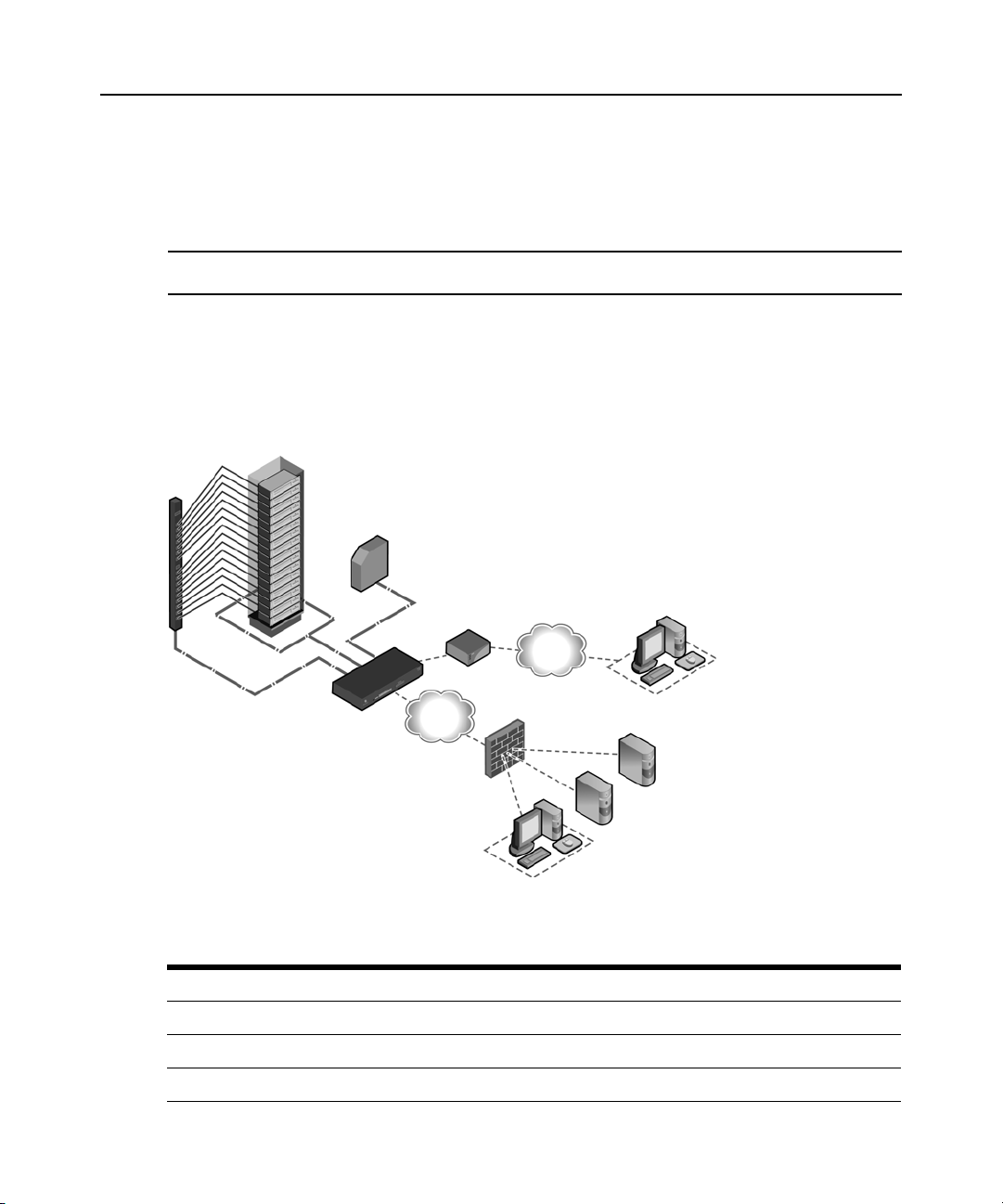
Configuration Example
The following graphic and table illustrate a typical ACS 6000 console server configuration.
Chapter 1: Introduction 5
Figure 1.1: Typical ACS 6000 Advanced Console Server Configuration
Table 1.1: Typical ACS 6000 Advanced Console Server Configuration Descriptions
Number Description Number Description
1 ACS 6000 advanced console server 8 Phone line
2 Target devices 9 Remote dial-in client
3 PDU (one or more) 10 Local Area Network (LAN)
Page 18

6 Cyclades ACS 6000 Advanced Console Server Installation/Administration/User Guide
Table 1.1: Typical ACS 6000 Advanced Console Server Configuration Descriptions (Continued)
Number Description Number Description
4 Serial port connection 11 LAN firewall
5 PC card (modem, Ethernet or storage) 12 Remote authentication server
6 Either AUX/Modem or any serial port 13 DSView client/server
7 Modem ordered and configured internally at the factory
-orExternal modem (on a device in one of the PC card slots
or USB port, or connected to a serial port or the AUX port)
14 Remote/local Windows/Linux
computer
Page 19
CHAPTER
Installation
2
Rack Mounting
You can mount the ACS 6000 console server in a rack or cabinet or place it on a desktop or other
flat surface. For rack or cabinet mounting, two mounting brackets are supplied with six hex screws
to connect the brackets to the console server. You will also need a Phillips screwdriver and the
appropriate nuts and bolts to connect the mounting brackets to the rack.
To rack mount the console server:
1. Install the brackets at the front or back edges of the ACS 6000 console server with the screws
provided with the mounting kit.
2. Mount the console server in a secure position.
7
Figure 2.1: Bracket Connections for Front Mount Configuration
Page 20
8 Cyclades ACS 6000 Advanced Console Server Installation/Administration/User Guide
231
Connecting the Hardware
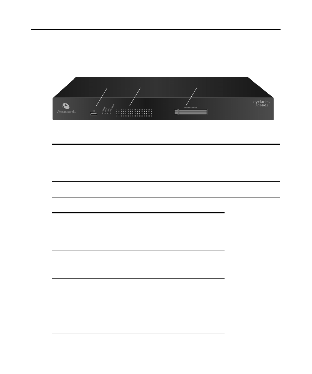
ACS console server connectors
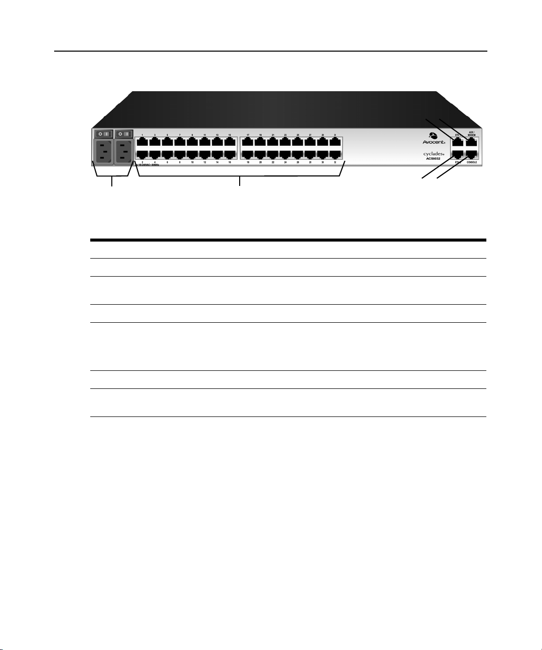
The following figure shows the connectors on the front of the ACS 6000 console server.
Figure 2.2: Front of the Console Server with PC Card Slots and LEDs (ACS 6032 Console Server Shown)
Table 2.1: Connectors on the Console Server Front
Number Description
1 USB connector. Supports the following USB devices: modem, wireless modem, storage and
USB hub.
2 LEDs. See Table 2.2.
3 PC card slots. Supports modem (wireless V.92), Ethernet, Fast Ethernet and storage device
Table 2.2: LEDs on the Console Server Front
Label Description
PWR/CPU Blue
ETH 0/ETH 1 • Amber - Link at 10BaseT speed
AUX/MODEM Dual LED: Yellow on top, green on bottom
[One LED for each serial port] Green
PC cards.
• Blinks - During unit boot
• Solid - During operation
• Off - Power is off
• Yellow - Link at 100BaseT speed
• Green - Link at 1000BaseT speed
• Off - No link/cable disconnected/Ethernet fault
• Yellow - DTR/DCD activity
• Green - TXD and RXD activity
• Off - No activity
• Blinks - Ready, with activity
• Solid - Ready
• Off - Not ready
Page 21
Chapter 2: Installation 9
1
3
2
5
6
4
The following figure shows the rear connectors on the console server.
Figure 2.3: Rear of the Console Server (ACS 6032 Console Server Shown)
Table 2.3: Connectors on the Console Server Rear
Number Description
1 Power supplies (dual AC shown). Models come with either single or dual AC or DC power.
2 Serial ports (32 ports shown). Models come with 16, 32 or 48 serial ports to connect to device
consoles, power devices or external modems.
3 ETH 1 10/100M/1G Ethernet port. Can be connected to a second network or used for failover.
4 AUX/Modem port - if an optional internal modem is ordered, this port is defined as a V.92
modem at the factory and can be used to connect the console server to a dedicated phone
line; otherwise, the port is factory-defined as RS-232 with an RJ-45 Cyclades pinout and can
be used to connect either an external modem or a power device.
5 ETH0 10/100M/1G Ethernet port for remote IP access.
6 Console port allows for local administration and access to connected devices through a
terminal or a computer with a terminal emulator.
Device consoles or modems to serial ports
Use CAT 5 or greater cables and DB-9 or DB-25 console adaptors as needed to connect target
device consoles or modems to the serial ports on the console server.
The ACS 6000 console server supports two different serial port pinout configurations, Cyclades
and Cisco
must reconfigure the pinout for the port. The administrator selects Units - Appliance Settings -
Ports - Physical Ports and selects the Cisco option from the RJ-45 Pinout drop-down menu.
®
. The default is Cyclades. If a Cisco cable is connected to the port, the administrator
Page 22

10 Cyclades ACS 6000 Advanced Console Server Installation/Administration/User Guide
The following tables show serial port pinout information, which you can use to create cables.
Table 2.4: Cyclades Serial Port Pinout
Pin No. Signal Name Input/Output
1 RTS OUT
2 DTR OUT
3 TxD OUT
4 GND N/A
5 CTS IN
6 RxD IN
7 DCD/DSR IN
8 Not Used N/A
Table 2.5: Cisco Serial Port Pinout
Pin No. Signal Name Input/Output
1 CTS IN
2 DCD/DSR IN
3 RxD IN
4 GND N/A
5 Not Used N/A
6 TxD OUT
7 DTR OUT
8 RTS OUT
To connect device consoles to serial ports:
Make sure the crossover cable used to connect a device has the same pinouts type that is configured
in the software for the port (either Cyclades or Cisco).
1. Make sure the power switches on devices are turned off.
2. To connect the console ports of devices to the serial ports, use CAT 5 or greater crossover
cables.
Page 23
Chapter 2: Installation 11
3. To connect modems, use straight-through CAT 5 or greater cables, wi th RJ-45 connectors on
one end and the appropriate connectors or adaptors (USB, DB-9 or DB-25) for the modem on
the other end.
See Power devices on page 11 for more information on connecting power devices.
See To install a pluggable device: on page 17 for more information on installing PC cards.
NOTE: To comply with EMC requirements, use shielded cables for all port connections.
WARNING: Do not turn on the power on the connected devices until after the console server is turned on.
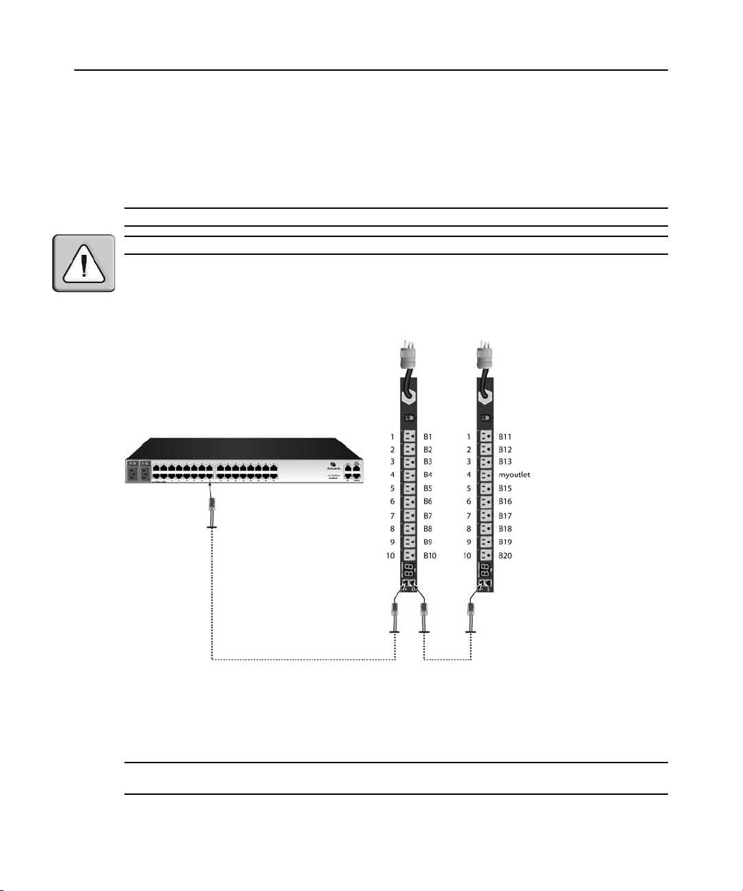
Power devices
The following figure shows two daisy-chained Cyclades PDUs connected to serial port 2 on a
console server.
Figure 2.4: Example: Daisy-chained Cyclades PDUs
To daisy-chain Cyclades PDUs to the console server:
This procedure assumes that you have one Cyclades PM PDU connected to a serial port on the
console server.
NOTE: Daisy chaining is not possible with SPC PDUs. ServerTech PDUs will allow only one level (Master and
Slave) of daisy chaining.
Page 24

12 Cyclades ACS 6000 Advanced Console Server Installation/Administration/User Guide
1. Connect one end of a UTP cable with RJ-45 connectors to the OUT port of the Cyclades PDU
connected to the serial port on the console server.
2. Connect the other end of the cable to the IN port of the next Cyclades PDU.
3. Repeat steps 1 and 2 until you have connected the desired number of Cyclades PDUs.
NOTE: For performance reasons, Avocent recommends connecting no more than 128 outlets per serial port.
NOTE: If the outlet has been assigned a name, such as “myoutlet,” entering myoutlet is sufficient and no other
path name is needed.
Power Configuration
The console server is supplied with single or dual AC or DC power supplies.
WARNING: Always execute the reboot command through the Web Manager or CLI under the Overview/Tools
node before power cycling the appliance. This will ensure that the reset doesn't occur while the file system in
Flash is being accessed and it helps avoiding Flash memory corruptions.
To configure AC power:
1. Make sure that the power switch on the console server is turned off.
2. Plug the power cable into the console server and into a power source.
3. Turn the console server on.
4. Turn on the power switches of the connected devices.
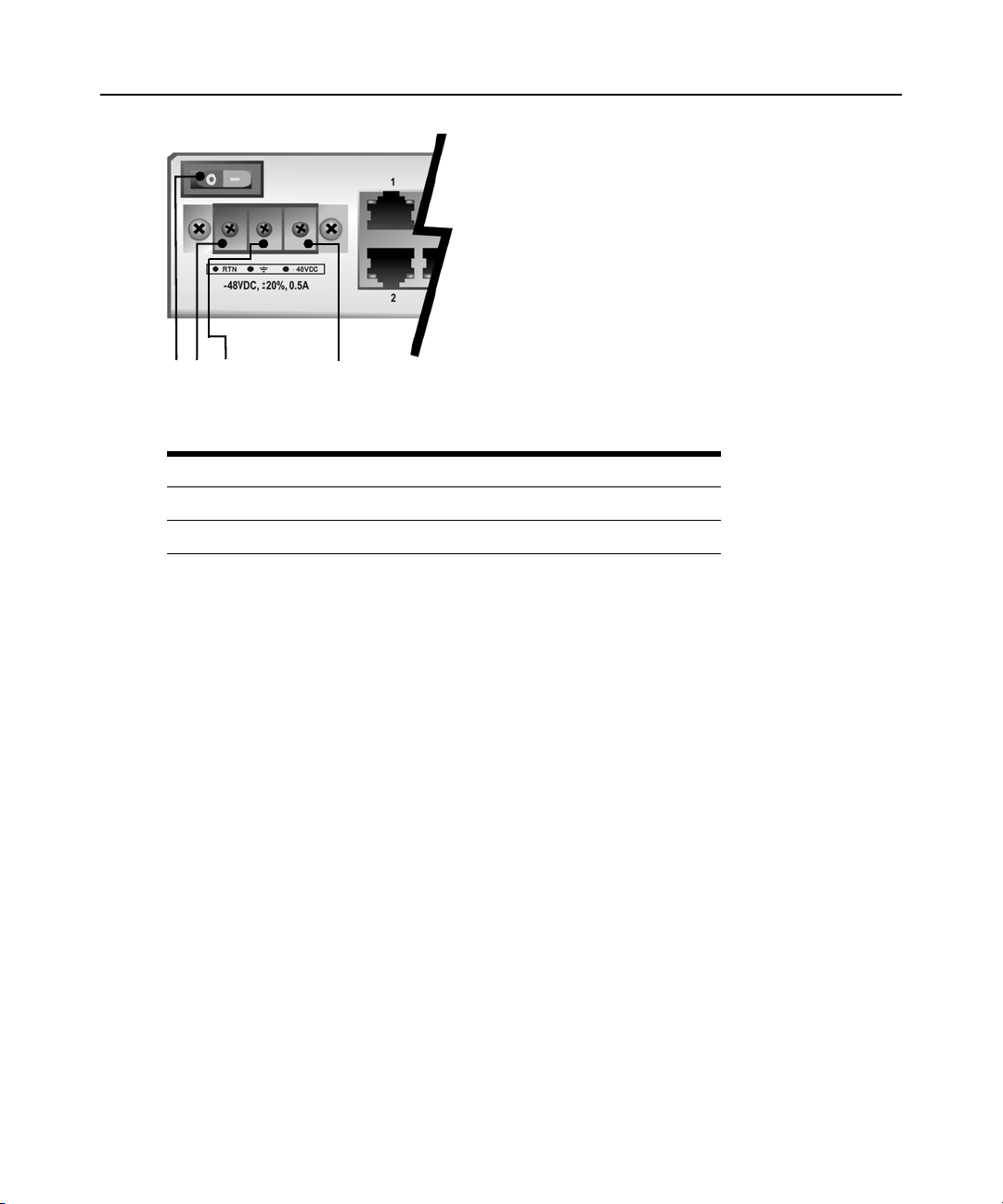
To configure DC power:
DC power is connected to DC-powered console servers by way of three wires: Return (RTN),
Ground (GND) and -48 VDC.
WARNING: It is critical that the power source supports the DC power requirements of your console server. Make
sure that your power source is the correct type and that your DC power cables are in good condition befor e
proceeding. Failure to do so could result in damage to the equipment or in personal injury.
The following diagram shows the connector configuration for connecting DC power. You may use
either a flat-blade or Phillips screwdriver for this procedure.
Page 25
Chapter 2: Installation 13
1 2 3 4
Figure 2.5: DC Power Connection Terminal Block
Table 2.6: DC Power Connection Details
Number Description Number Description
1 Power switch 3 GND (Ground)
2 RTN (Return) 4 -48 VDC
1. Make sure that the power switch on the console server is turned off.
2. Make sure that DC power cables are not connected to a power source.
3. Remove the protective cover from the DC power block by sliding it to the left or right.
4. Loosen all three DC power connection terminal screws.
5. Connect your return lead to the RTN terminal and tighten the screw.
6. Connect your ground lead to the GND terminal and tighten the screw.
7. Connect your -48 VDC lead to the -48 VDC terminal and tighten the screw.
8. Slide the protective cover back into place over the DC terminal block.
9. If your console server has dual-input DC terminals, repeat steps 3 - 8 for the second terminal.
10. Connect the DC power cables to the DC power source and turn on the DC power source.
11. Turn on the console server.
12. Turn on the power switches of the connected devices.
ACS 6000 Remote Console Server Configuration
You may make an Ethernet connection or a direct connection to access the remote console switch.
For information on accessing the Web Manager and performing first time configuration steps, see
Using the Web Manager on page 15 and First Time Configuration on page 19.
Page 26

14 Cyclades ACS 6000 Advanced Console Server Installation/Administration/User Guide
Making an Ethernet connection
To make an Ethernet connection, connect an Ethernet cable to the port labeled 10/100/1000Base-T
and to an Ethernet hub or switch.
Making a direct connection
To connect a computer or terminal to the console port:
1. Connect a CAT 5 straight-through cable with RJ-45 connectors to one of the supplied RJ-45
adaptors.
2. Connect the RJ-45 end of the cable to the Console port on the console server.
3. Connect the adaptor end of the cable either to a terminal or a computer that has a terminal
emulation program.
To configure network parameters:
1. Connect to the Console port using a terminal or computer with a terminal emulation program.
2. Make sure the terminal settings are: 9600, 8, N and 1, flow control None.
3. Log in to the console server as admin, with the default password avocent. The CLI prompt
appears.
--|- units cli->
4. At the command prompt, enter wiz to view and/or change the current IP configuration.
--|- units cli-> wiz
5. Set the IP configuration for Eth0 by pressing Enter to maintain the current value, Tab + Tab to
see the option(s) or
eth0:
IPv4 Address: 172.26.30.241
IPv6 Address:
status :
ipv4_method :
ipv6_method :
MAC Address: 00:e0:86:0c:57:5d
dns:
primary :
secondary :
domain :
hostname :
6. Type yes to confirm and save the new configuration.
Are all these parameters correct? (no, yes, quit) [no] :
Esc + Tab to see the current parameter value for editing.
NOTE: DHCP is the default IP configuration. A fixed IP address must be available for users to access the Web
Manager.
Page 27

Accessing an ACS Console Server
Using the Web Manager
An IP address is needed to launch the Web Manager in a browser. The IP address is usually
configured as a static IP address assigned to the console server during initial configuration. If
DHCP is used, then the user must be able to discover the IP address assigned by the DHCP server.
The console server ships with DHCP enabled. Users can access the Web Manager with either a
DHCP-assigned IP address, an administrator-assigned static IP address or the default IP address
(192.168.160.10). For information on how to log in, see
If you do not configure a static address, if a DHCP server is not on the network or if it fails to
discover the IP address of the console server, you can enter the default static IP/subnet mask
addresses of 192.168.160.10/255.255.255.0 for eth0 and 192.168.161.10/255.255.255.0 for eth1.
To use the default IP address to access the Web Manager:
Both the desktop and the console server should be in the same physical network. Add the host route
192.168.160.10/32 to the Ethernet interface. The following example adds the route to eth0 on the
console server on a Linux machine:
# route add - host 192.168.160.10 eth0
To log into the Web Manager:
Chapter 2: Installation 15
To log into the Web Manager: on page 15.
1. Enter the IP address of the console server in the address field of a browser.
2. Enter your username and password.
NOTE: Username and password are case sensitive.
NOTE: After logging into the Web Manager for the first, you must complete the First Time Configuration screen.
See First Time Configuration on page 19 for more information.
Using Telnet/SSH
An authorized user can use a Telnet or SSH client to make a connection directly to the console of a
device if the following are true:
• The Telnet or SSH protocol is enabled in the selected security profile.
• The Telnet or SSH protocol is configured for the port.
• The Telnet or SSH client is available, and it is enabled on the computer from which the
connection is made.
To view and connect to devices with the Web Manager:
1. Select Topology in the side navigation bar. The content area displays the name of the console
server.
Page 28

16 Cyclades ACS 6000 Advanced Console Server Installation/Administration/User Guide
2. Select the down arrow next to the console server name. A list of either default port names or
administrator-defined aliases for all installed and configured devices for which the user is
authorized appears.
3. Select Serial Viewer from the Action column. A Java applet viewer appears. In a gray area at
the top of the viewer, the Connected to message shows the IP address of the console server
followed by the default port number or alias.
4. Log in if prompted.
To use Telnet to connect to a device through a serial port:
For this procedure, you need the username configured to access the serial port, the port name (for
example, 14-35-60-p-1), device name (for example, ttyS1), TCP port alias (for example, 7001) or
IP port alias (for example, 100.0.0.100) and the hostname of the console server or its IP address.
The following example assumes that the Telnet service is supported on the operating system where
the telnet command is entered.
To use a Telnet client, enter the information in the dialog boxes of the client.
-orTo use Telnet in a shell, enter the following command:
# telnet hostname | IP_address
login: username:[portname | device_name]
-or-
# telnet hostname TCP_Port_Alias
login: username
-or-
# telnet IP_Port_Alias
login: username
To close a Telnet session:
Enter the Telnet hotkey defined for the client. The default is Ctrl ] + q to quit, or enter the text
session hotkey for the CLI prompt and then enter
quit.
To use SSH to connect to a device through a serial port:
For this procedure, you need the username configured to access the serial port, the port name (for
example, 14-35-60-p-1) or device name (for example, ttyS1), and the hostname of the console
server, IP address or IP Port alias (for example, 100.0.0.100).
To use an SSH client, enter the information in the dialog boxes of the client.
-or-
Page 29

To use SSH in a shell, enter the following command:
ssh -l username:port_name [hostname | IP_address]
-or-
ssh -l username:device_name [hostname | IP_address]
-or-
ssh -l username IP_Port_Alias
To close an SSH session:
At the beginning of a line, enter the hotkey defined fo r th e SSH cli e nt followed by a period. The
default is
~. Or, enter the text session hotkey for the CLI prompt and then enter quit.
Pluggable Devices Installation and Configuration
Insert and configure pluggable devices (PC cards and/or USB devices) only after you enable PC
Card and USB Device Detection, as described in the following procedure.
Go to http://www.avocent.com to see the current list of supported pluggable devices.
NOTE: When a pluggable device is not listed in the internal database, the Device Info column may show no text
at all or show different text based on the type of card. One example is Unknown device f024 (rev 01).
Chapter 2: Installation 17
NOTE: When a pluggable device is not in the current list of supported pluggable devices (PC cards and USB
devices), if the device is detected by the console server, the console server attempts to configure the device with
standard settings. The device might operate normally but it might not be supported by Avocent.
To enable Pluggable Device Detection:
1. Select Appliance Settings - Security - Security Profile in the Web Manager. The Security
Profile content area is displayed.
2. Select Enabled from the PC Card and USB Device Detection drop-down menu.
NOTE: When using wireless devices, changes made to a configuration will take effect only after the device is
ejected and then re-inserted.
To install a pluggable device:
1. Insert the PC card into slot 1 or slot 2 or connect the USB device in the USB port.
2. Select Appliance Settings - Pluggable Devices in the Web Manager. The Pluggable Devices
content area is displayed. If Pluggable Devices Detection is enabled, the inserted pluggable
device’s Device Name, Device Type and Device Info are shown.
NOTE: A hard disk PC card and a USB storage device are automatically mounted and configured once it is
inserted.
Page 30

18 Cyclades ACS 6000 Advanced Console Server Installation/Administration/User Guide
To configure a pluggable device:
1. Select Application Settings - Pluggable Devices in the Web Manager. The Pluggable Devices
content area is displayed and all mounted pluggable devices are shown.
2. Click on the pluggable device name. The page for the pluggable device type is displayed.
3. Configure the pluggable device parameters.
NOTE: PC card and USB storage devices are automatically configured.
To eject a pluggable device:
CAUTION: Always use the Web Manager to eject a pluggable device. Any other method may cause a kernel
panic.
1. Select Application Settings - Pluggable Devices in the Web Manager. The Pluggable Devices
content area is displayed and all mounted pluggable devices are shown.
2. Select the checkbox next to the pluggable device name you want to eject, then click Eject.
3. Remove the pluggable device by removing the PC card from the slot or the USB device from
the USB port.
Page 31

CHAPTER
Web Manager Overview
3
An ACS 6000 console server can be accessed and managed via the Web Manager, SSH or Telnet.
First Time Configuration
The first time that the admin logs into the Web Manager after installation, the First Time
Configuration screen appears. An administrator uses the options in the left menu to enable and
configure security, ports and users.
To open the First Time Configuration screen:
1. Open a web browser and enter the console server IP address in the address field.
2. Log in as admin with the password avocent. The First Time Configuration screen appears.
19
To configure security parameters and select a security profile (First Time Configuration):
1. Select Security from the lef t menu on the Fir st T ime Configuration screen. The Security Profile
screen appears.
2. (Optional) To enable the console server to automatically detect and download drivers from
connected pluggable devices, select the checkbox next to PC Card and USB Device Detection.
3. (Optional) To enable RPC, select the RPC checkbox.
4. (Optional) To enable the security option that supports group authorizations for port access,
select the checkbox next to Port access is controlled by authorizations assigned to user
groups.
5. Either select one of the default security profiles from the Security Profile pull-down menu, or
select Custom to configure a customized security profile.
6. Click Save.
7. If the Custom Security Profile is selected, perform the following steps.
a. Select the Custom option from the left menu.
b. Click the checkboxes and enter values as needed to configure the services, SSH and WEB
(HTTP and HTTPS) options to conform with your site security policy.
c. Click Save.
Page 32

20 Cyclades ACS 6000 Advanced Console Server Installation/Administration/User Guide
To configure users and change the default user passwords (First Time Configuration):
WARNING: For security reasons, it is recommended that you change the default password for both root and
admin users immediately.
1. Select Users from the left menu on the First Time Configuration screen. The User Names
screen appears.
2. Do the following twice to change the default password for root and for admin.
a. Click the username (admin or root).
b. Enter the new password in the Password and the Confirm Password fields.
c. Click Save to save the new password.
3. Do the following as many times as needed to configure new user accounts and assign them to
default groups.
a. Click Add.
b. Enter the username in the User Name field.
c. Enter the new password in the Password and the Confirm Password fields.
d. (Optional) Force the user to change the password, select the checkbox for User must
change password at next login.
e. Assign the user to one or more groups.
NOTE: By default, all configured users can access all enabled ports. Additional configuration is needed if your
site security policy requires you to restrict user access to ports.
f. (Optional) Configure account expiration and password expiration.
g. Click Save.
NOTE: The admin and all users in the administrator group can also select Appliance Settings-Users-Local
Accounts-User Names to configure users.
To enable and configure all ports (First Time Configuration):
1. Select Ports from the left menu on the First Time Configuration screen. The Default Settings
screen appears.
2. Select the connection protocol that users can use for direct connections to all ports from the
Protocol pull-down menu, either Telnet, SSH or Telnet/SSH.
NOTE: The service must also be enabled in the security profile that is in effect.
3. Select a default authentication type that applies to all port logins from the Authentication Type
pull-down menu.
4. To enable the software to automatically discover the names of devices connected to the ports,
click the Enable auto discovery checkbox.
Page 33

Chapter 3: Web Manager Overview 21
5. Configure the remaining port parameters as needed.
6. Click Save.
7. Select Physical Ports from the left menu. The Physical Ports screen appears.
8. To enable and perform additional configu rati on on all ports at once, click the checkbox on the
top line of the ports list.
9. To enable and perform additional configuration on one or more ports at once, click the
checkbox(es) on the entry for each port.
10. Click Edit.
11. To enable the selected port(s), select Enabled from the Status menu.
12. (Optional) To change the default pinout when a Cisco cable is connected to the selected
port(s), select Cisco from the RJ-45 Pinout menu.
13. For port(s) connected to the console of a target device, leave CAS selected in the Serial Profile
menu.
14. For port(s) connected to a PDU, select Power from the Serial Profile menu.
15. For port(s) connected to a modem, select Dial-in from the Serial Profile menu.
16. To reconfigure the connections settings to match the device(s) connected to the selected
port(s), make the needed changes in the Communication Settings area of the screen.
NOTE: The administrator can also select Units - Appliance Settings - Ports - Default Settings and Units -
Appliance Settings - Ports - Physical Ports to enable and configure individual ports and perform other advanced
configuration.
17. Click Save.
To close the First Time Configuration screen:
Select Finish from the left menu on the First Time Configuration screen.
Page 34

22 Cyclades ACS 6000 Advanced Console Server Installation/Administration/User Guide
1
2
3
4
Web Manager Overview for Administrators
The following figure shows a typical screen when an administrator is logged into the Web
Manager.
Figure 3.1: Administrator Web Manager Screen
Table 3.1: Web Manager Screen Areas
Number Description
1 Top option bar. The name of the logged in user appears on the left side and Refresh, Print, Logout
and Help buttons appear on the right.
2 Tab bar. Only the Units tab appears for the ACS 6000 Web Manager.
3 Side navigation bar. Menu options for configuration, viewing of system information and access to
devices. The options change based on user type.
4 Content area. Contents change based on the options selected in the side navigation bar.
Page 35

Chapter 3: Web Manager Overview 23
The following table provides an overview of the tools under Appliance Settings that are used by
administrators to configure the system.
Table 3.2: Web Manager Options for Administrators
Heading Description
Global Settings
• Sessions
•Sensors
• Data Buffering
Network
•IPv6
• Devices
• Bonding
• IPv4 Static Routes
• IPv6 Static Routes
•DNS
•Hosts
Ports
• Physical Ports
•CAS Profile
• Dial-in Profile
• Power Profile
•Click Sessions to configure global session parameters for idle time-out, data
logging, destination, timestamp and alert strings.
•Click Sensors to set maximum and minimum temperature values to generate
alarms.
•Click Data Buffering to configure global parameters for data buffering.
•Click IPv6 to enable or disable IPv6 protocol for the console server.
•Click Devices to get the name and status of the device and to enable and
configure the IP address for the eth0 and eth1 interfaces.
•Click Bonding to enable or disable failover to eth1 if eth0 fails.
•Click IPv4 Static Routes or IPv6 Static Routes to add a static route or modify
the default route.
•Click DNS to specify the console server hostname and primary and
secondary domain name servers.
•Click Hosts to add or delete host table entries.
•Click Physical Ports to enable and configure the serial and AUX ports.
•Click CAS Profile to configure the following for ports connected to device
consoles and configured with the CAS Profile: data buffering and syslogging,
communication protocols (Telnet/SSH), authenticating and other
communications parameters, port names, power management while
connected, auto discovery and auto answer settings.
•Click Dial-in Profile to configure ports connected to modems and to configure
secure dial-in settings such as OTP login, PPP connections and PPP/PAP
authentication, and to configure callback and PPP passphrases for OTP
users.
•Click Power Profile to (optionally) configure the PDU type, poll interval and to
change the login password for each type of PDU device to match any
changes made on the PDU and to configure groups of outlets.
Pluggable Devices Click Pluggable Devices to insert, configure and eject pluggable devices that are
inserted into the PC card slots and/or connected in the USB port.
Security
• Security Profile
•Custom
•DSView
Authentication
• Appliance Authentication
• Authentication Servers
•Click Security Profile to configure your security profile and other security
parameters (PC Card Detection, RPC and whether port access is controlled
by authorizations assigned to user groups).
•Click Custom to create a custom security profile.
•Click DSView to enable the appliance to be managed by DSView software or
to clear the DSView certificate.
•Click Appliance Authentication to configure authentication for the console
server. (Configure port authentication under Ports - CAS Profile - Default
Settings - General.)
•Click Authentication Server to specify the network authentication server.
Page 36

24 Cyclades ACS 6000 Advanced Console Server Installation/Administration/User Guide
Table 3.2: Web Manager Options for Administrators (Continued)
Heading Description
Users
• Local Accounts
• Authorization
Syslog Click Syslog to specify syslog destination(s), either local (appliance console or a
Event Notifications
• Settings
• Events
Firewall
• IPv4 Filter Table
• IPv6 Filter Table
IPSec(VPN) Click IPSec(VPN) to configure IPSec (VPN) connections, authentication and
SNMP
• System
•SNMP v1/v2/v3
Date and Time
• Date & Time
• Time Zone
•Click Local Accounts to configure users, assign them to pre-defined user
groups, configure expiration of the password and the account and configure
other password rules (complexity and default expiration).
•Click Authorization to add new user groups, to add users to user groups and
to authorize the user group and its members for: port access, power
management, data buffer management and appliance administration rights
(which include the right to view appliance information, reboot, disconnect
sessions, upgrade firmware, configure the appliance and users, backup and
restore configuration, access the Linux shell and transfer files).
root session) or remote (IPv4 or IPv6).
•Click Settings to specify the syslog facility number and settings for SNMP
traps, SMS, email or DSView server message destinations.
•Click Events to specify which events to detect for the console server and to
select the destination for each event message type.
Click IPv4 Filter Table or IPv6 Filter Table to configure the chains and rules for
packet filtering.
NAT traversal.
•Click System to view or edit SysContact and SysLocation information.
•Click SNMP v1/v2/v3 to add, edit or delete an SNMP system management
interface (SMI) type (combined v1/v2 or v3).
•Click Date & Time to set the date and time for the console server manually or
configure an NTP server.
•Click Time Zone either to select a pre-defined time zone or to define a custom
time zone.
Boot Configuration Click Boot Configuration to specify whether the console server boots from Flash
Online Help Click Online Help to specify the URL for the online help after the online help files
memory or from the network and to configure the watchdog timer, a specific
mode for the eth0 and eth1 interfaces and the console speed.
are downloaded and installed on a local web server.
Page 37

Web Manager Overview for Regular Users
1
2
3
4
The following figure shows features of the Web Manager for a regular user.
Figure 3.2: Web Manager Regular User Screen
Table 3.3: Web Manager Regular Users Screen Functional Areas
Number Description
1 Top option bar. The name of the logged in user appears on the left side and Refresh, Print, Logout
and Help buttons appear on the right.
Chapter 3: Web Manager Overview 25
2 Tab bar. Only the Units tab appears for the ACS 6000 Web Manager.
3 Side navigation bar. Menu options appear that are available for regular users.
4 Content area. Contents change based on the options selected in the side navigation bar.
The following table provides an overview of the options for regular users.
Table 3.4: Web Manager Options for Regular Users
Menu Option Description
Topology Select the down arrow next to the console server name to expand the list of ports
Overview • View the name and type of console server. Select Tools to Reboot, Upgrade
you are authorized to access.
• For port type Serial, select the name of the port and click in the Serial Viewer to
connect to the device.
• For port type Power (type shows the PDU model), select the name of the PDU
to manage power on this PDU’s outlets that you are authorized to manage.
Firmware, view Appliance Session, Save Configuration or Restore
Configuration.
• Click Appliance Session to access the console server.
Page 38

26 Cyclades ACS 6000 Advanced Console Server Installation/Administration/User Guide
Table 3.4: Web Manager Options for Regular Users (Continued)
Menu Option Description
Power Management
• Settings
• Management
• Outlet Groups
Monitoring
• Devices
• IPv4 Routing Table
• IPv6 Routing Table
• Serial Status
• Serial Statistics
User Profile
• Change Password
• Select Settings and select the name of a PDU. Rename, restore the factory
defaults or configure the selected PDU. For more information, see Chapter 4.
• Select Management and select the name of a PDU to reboot or manage the
PDU and its outlets. For more information see Chapter 4.
• Select Outlet Groups and select the name of an outlet group to manage.
• Select Network - Devices to view the current IP for Ethernet interfaces.
• Select Network - IPv4 or IPv6 Routing to view the current routing table.
• Select Serial Status or Serial Statistics to view the status or statistics of the
serial ports.
Change your own password.
Page 39

CHAPTER
Using the Web Manager
4
Global Settings
Global settings for the ACS 6000 console server are for configuring operating parameters so that
you can vary how long a session can be idle before it times out, enabling session logging and alerts,
setting the minimum and maximum values for the console server’s temperature sensors and
configuring data buffering.
Sessions
To configure Sessions:
1. Click Appliance Settings - Global Settings. The Sessions window will be displayed.
2. Enter the desired period in seconds for how long the ACS 6000 console server can be idle before timing out and requiring another login.
27
NOTE: To set the console server so that there is no idle time-out, enter zero.
3. (Optional) Click Enable appliance session data logging. This will activate the Destination and
4. (Optional) Click Enable appliance session data logging alerts. This will activate the Alert
5. Enter the desired alert strings (up to ten) in the fields provided.
6. Click Save.
Sensors
The ACS 6000 console server has sensors that monitor the internal temperature. You can specify an
operating range for the console server that fits its environment.
CAUTION: Do not use values that exceed the maximum and minimum temperatures listed in Techical
Specifications on page 69.
Timestamp settings.
a. Select the destinatio n for appli a nce session data logs from the pull -d own m enu. Choices
are Local, NFS, Syslog and DSView.
b. Enable or disable timestamping the appliance session data logs.
String fields.
Page 40

28 Cyclades ACS 6000 Advanced Console Server Installation/Administration/User Guide
To configure the temperature sensors:
1. Click Appliance Settings - Global Settings - Sensors. The Sensors window will be displayed.
2. In the Maximum T emperature fiel d, enter the temperature in degrees Celsius that, if exceeded, will generate an event notification.
3. In the Maximum Temperature Threshold field, enter the temperature threshold in degrees Celsius below the maximum temperature.
NOTE: When this threshold is reached, the sensor will generate an event notification that the console server has
returned to normal operating temperature. This is also true for setting the Minimum Temperature Threshold.
4. In the Minimum T emperature field, enter the temperature in degrees Celsius that, if the console server’s temperature falls below, will generate an event notification.
5. In the Minimum Temperature Threshold field, enter the temperature threshold in degrees Celsius above the minimum temperature.
6. Click Save.
Data buffering
To configure data buffer storage:
1. Select Appliance Settings - Global Settings - Data Buffering. The Data Buffering screen appears.
2. Enter the segment size in kilobytes and spare segments in the Local Data Buffering Settings section.
3. In the NFS Data Buffering Settings section, enter the following information: NFS Server, NFS Path, Segment Size (Kbytes) and Spare Segments.
NOTE: RPC service must be enabled in the Security Profile screen before configuring NFS Data Buffering
Settings. NFS does not support IPv6.
4. Configure data buffer storage on a syslog server in the Syslog Data Buffering Settings section; select a facility number from the drop-down menu: Log Local 0, Log Local 1, Log Local 2, Log Local 3, Log Local 4 or Log Local 5.
5. Click Save.
Network Configuration
You can display and configure the network options for IPv6, devices, bonding, IPv4 and IPv6 static
routes, DSN and hosts.
IPv6 options
To configure IPv6:
1. Select Appliance Settings - Network - IPv6. The IPv6 screen appears.
2. Click Enable IPv6 to configure the console server for IPv6 protocol operation.
Page 41

3. Click Get DNS from DHCPv6 to obtain the Domain Name Server IP address from the DHCP server.
4. Click Get Domain from DHCPv6 to obtain the domain name from the DHCP server.
5. Click Save. An alert window displays the notice, Enabling or disabling IPv6 requires r eboot to be effective. Click OK. The login screen appears when the reboot is complete.
Devices options
An administrator can select, enable and configure the IP addresses assigned to the network
interfaces and view the MAC address. Besides the two standard Ethernet interfaces, the list of
network interfaces includes entries for any Ethernet PC cards that may be installed.
To configure a network device:
1. Select Appliance Settings - Network - Devices. The Devices screen appears with a list of network interfaces and their status (enabled or disabled).
2. Click the name of the network device to configure. The Settings screen appears.
3. Select the status (either Enabled or Disabled) from the drop-down menu.
4. Select one of the following IPv4 method options:
• Select DHCP to have the IPv4 IP address set by the DHCP server.
• Select Static to enter the IPv4 IP address and subnet mask manually.
• Select IPv4 address unconfigured to disable IPv4.
5. Select one of the following IPv6 method options:
• Select Stateless if the link is restricted to the local IP address.
• Select DHCPv6 to have the IPv6 IP address set by the DHCP server.
• Select Static to enter the IPv6 IP address and prefix length manually.
• Select IPv6 address unconfigured to disable IPv6.
Chapter 4: Using the Web Manager 29
NOTE: The MAC Address for the device will be displayed after this option.
NOTE: The following step is only active for mounted Ethernet PC cards.
6. Enter the following Wireless LAN information: a. Select MyPrivateNet (E SS ID) to enter the unique identifier for the wireless access point. b. Select Channel to enter the communication channel with the access point. c. Select Encrypted to enable data encryption during transmission. d. Enter the key or password to decode incoming encrypted data.
7. Click Save, then click Close.
Page 42

30 Cyclades ACS 6000 Advanced Console Server Installation/Administration/User Guide
Bonding options
An administrator can enable and configure Ethernet bonding (also called failover). When bond ing
is enabled, the eth0 interface is used for access, and eth1 is used if the eth0 interface fails.
To enable bonding:
1. Select Appliance Settings - Network - Bonding. The Bonding screen is displayed.
2. Click Bonding with eth0 as primary and eth1 as second mode of access to enable network bonding.
3. Set the following values:
• MII MON - The interval (in milliseconds) at which the active interface is checked to see if
it is still communicating.
• Up Delay - The time (in milliseconds) that the system waits before it makes the primary
interface active after the primary interface is detected as up.
4. Click Save, then click Close.
IPv4 and IPv6 static routes options
To add static routes:
1. Select Appliance Settings - Network - IPv4 Static Routes or IPv6 Static Routes. Any existing static routes are listed with their Destination IP/Mask, Gateway, Interface and Metric values shown.
2. Click Add. The Add Static Route form is displa yed.
3. Select Default to configure the default route.
• Select either Gateway or Interface from the Route through drop-down menu.
• Enter the IP address of the gateway or the name of the interface in the Gateway IP Or
Interface field.
• Enter the number of hops to the destination in the Metric field.
-orSelect Host IP Or Network to enter custom settings for Destination IP/Mask.
• Select either Gateway or Interface from the Route through drop-down menu.
• Enter the required Destination IP/Mask with the syntax <destination IP>/<subnet mask>/
<CIDR> in the Destination IP/Mask field.
• Enter the IP address of the gateway or the name of the interface in the Gateway IP Or
Interface field.
• Enter the number of hops to the destination in the Metric field.
4. Click Save, then click Close.
Page 43

To edit Static Routes:
1. Select Appliance Settings - Network - IPv4 Static Routes or IPv6 Static Routes. Any existing static routes are displayed with their Destination IP/Mask, Gateway, Interface and Metric values shown.
2. Click a route name under Destination IP/Mask. The Static Routes edit screen appears.
3. Edit any of the static route fields.
4. Click Save, then click Close.
DNS options
An administrator can select configure primary and secondary domain name system (DNS) servers.
To configure DNS:
1. Select Appliance Settings - Network - DNS. The DNS configuration page is displayed.
2. Enter the Primary DNS IP address.
3. Enter the Secondary DNS address.
4. Enter the Domain name, for example, corp.avocent.com (default).
5. Enter the hostname of the console server, for example, ACS60<#ports> - <serial#> (default).
6. Click Save.
Chapter 4: Using the Web Manager 31
Host options
An administrator can configure a table of host names, IP addresses and host aliases for the local
network.
To add a host:
1. Select Appliance Settings - Network - Hosts. The Hosts page is displayed and contains the IP address, Hostname and Alias for all local hosts on the network.
2. Click Add to add new host. The Add Host Wizard page is displayed.
3. Enter the IP address, hostname and alias of the host you want to add.
4. Click Save, then click Close.
To edit a host:
1. Select Appliance Settings - Network - Hosts. The Hosts page is displayed and contains the IP address, Hostname and Alias for all local hosts on the network.
2. Click on the IP address of the hostname that you want to edit. The settings screen is displayed.
NOTE: The IP address of the selected host is shown but cannot be edited from this screen.
3. Enter a new hostname and alias, as applicable.
4. Click Save, then click Close.
Page 44

32 Cyclades ACS 6000 Advanced Console Server Installation/Administration/User Guide
Ports Configuration
Physical Ports
An administrator can enable and configure serial ports and auxiliary ports. On the serial ports
screen, you can enable serial ports, specify the connection profile (CAS, Dial-In or Power) based
on the type of connected device, optionally configure the port with a Ci sco pinou t if required and
configure communication settings. On the auxiliary ports screen, you can enable the auxiliary port
and configure it based on the type of connected device.
To enable or disable, change the pinout, select a Serial Profile and configure communication settings for one or more serial ports:
1. Select Appliance Settings - Ports - Physical Ports - Serial Ports. The Serial Ports screen appears.
2. Click the port number or the checkbox for each port you want to configure.
3. Click Edit.
4. Select Enabled or Disabled from the Status menu.
5. (Optional) To change the default pinout when a Cisco cable is connected to the selected port(s), select Cisco from the RJ-45 pinout menu.
6. For port(s) connected to the console of a target device, select CAS from the Serial Profile menu.
7. For port(s) connected to a modem, select Dial-in from the Serial Profile menu.
8. For port(s) connected to a PDU, select Power from the Serial Profile menu.
9. To reconfigure the connections settings to match the device(s) connected to the selected port(s), make the needed changes in the Communication Settings area of the screen.
10. Click Save, then click Close.
To enable and configure the auxiliary port for a connected modem or PDU:
If an internal modem is not already installed at the factory, you can connect an external modem or a
PDU to the AUX/Modem port. Perform this procedure to configure the auxiliary port.
1. Select Appliance Settings - Ports - Physical Ports - Auxiliary Ports. The Auxiliary Ports form appears.
2. Click the port number. The Aux Ports Settings form appears.
3. Select Enabled or Disabled from the Status menu.
4. If the port is connected to a PDU, select Power from the Serial Profile menu.
5. If the port is connected to a modem, select Dial-in from the Serial Profile menu.
6. Click Save, then click Close.
Page 45

CAS Profile
An administrator can configure settings for ports that are assigned to the CAS Profile. The CAS
Profile option has four options shown in the following table.
Table 4.1: CAS Profile Options
Option Description
Default Settings Configure the connection protocol, authentication, auto discovery and other general
Devices Configure one or more ports that have the CAS Profile
Auto Answer Configure an auto answer input and output string
Chapter 4: Using the Web Manager 33
settings
Auto Discovery Configure settings and probe and match strings for ports that are configured for auto
discovery. When auto discovery is enabled, if the hostname of the connected target
device is successfully discovered, the hostname is shown instead of the serial port
alias. This feature can save time for administrators because they do not need to enter
port aliases manually. If the console server is being managed through DSView 3
software, hostname discovery can be configured through the DSView 3 software.
Probe and match strings are used to probe the target device that is connected to the
serial port and to extract a hostname from the answer that is received in response to the
probe string. The result of each probe string is compared against all match strings.
Each time no match is found, the next probe string is sent until there are no more probe
strings.
Default probe and answer strings used for auto discovery have a broad range and work
in most cases. An administrator can configure site-specific probe strings and answer
strings. Probe string configuration requires knowledge of C-style escape sequences.
Match strings require knowledge of POSIX extended regular expressions. Hostnames
longer than 31 characters are truncated when the hostname is assigned to the serial
port alias.
To configure the protocol, authentication, auto discovery and other general settings for ports configured with CAS Profile:
1. Select Appliance Settings - Ports - CAS Profile - Default Settings - General. The General screen appears.
NOTE: Default settings to the CAS Profile are intended for new CAS ports. CAS ports with previously-configured
default settings will not be affected unless they are edited in Appliance Settings - Ports - Physical Ports or by
using the Multi-Edit Wizard in Appliance Settings - Ports - CAS Profile - Devices.
2. Select the desired protocol(s) (SSH, Telnet or Telnet/SSH) that can be used to access the serial port/target device from the Protocol pull-down menu.
3. Select the desired authentication type from the drop-down menu.
NOTE: Port authentication authenticates the user for one session.
Page 46

34 Cyclades ACS 6000 Advanced Console Server Installation/Administration/User Guide
4. To enable auto discovery, select the Enable auto discovery checkbox.
5. Perform other configurations on the screen as required.
6. Click Save.
To enable and configure alerts for ports configured with CAS Profile:
1. Select Appliance Settings - Ports - CAS Profile - Default Settings - Alerts. The Alerts screen appears.
2. To activate the alert string fields, click the Enable alert strings checkbox.
3. Enter up to ten alert strings in the fields provided.
NOTE: Special event notifications are generated when input data matches one of the alert strings.
4. Click Save.
To enable and configure data buffering for ports configured with CAS Profile:
1. Select Appliance Settings - Ports - CAS Profile - Default Settings - Data Buffering. The Data Buffering screen is displayed.
2. Choose Enabled or Disabled data buffering from the Status checkbox.
3. Chose the type of data buffering desired from the Type drop-down menu.
4. Choose Enabled or Disabled from the Time Stamp and Login/Logout Message drop-down menus.
5. Choose Enabled (store data always) or Disabled (store data when no CAS session is open) from the Serial Session Logging drop-down menu.
6. Click Save.
To edit the CAS Profile parameters for one or multiple ports:
1. Select Appliance Settings - Ports - CAS Profile - Devices. The Devices screen appears with a
list of all ports that are configured with the CAS Profile. (Device is the name of the port and
Name is the configured or discovered name of the connected device.)
2. To edit multiple ports, perform the following steps. a. Select the checkbox for each port individually or select the checkbox on the heading row
to select all listed ports. The Multi-Edit button is activated.
b. Click the Multi-Edit button. The Multi-Edit Wizard screen appears.
c. Select the checkboxes to activate configuration opt ions for Configure CAS General
Settings, Configure Alerts Strings or Configure Data Buffering Settings.
d. Select the checkboxes in each section to enable or disable the individual options.
e. Click Next. The following screen will depend on the options selected in sub-step c above.
3. To edit one port, perform the following steps. a. Click the port name in the Device column. The General, Alerts, Data Buffering and Power
options appear in the side navigation bar with the General option selected.
Page 47

Chapter 4: Using the Web Manager 35
b. To enable the port, specify the connection protocol, configure authentication, enable auto
discovery, configure the name and other general settings, then select the General option.
c. To enable and configure up to ten strings to generate event notifications if detected during
a session, select the Alerts option.
d. To enable and configure data buffering, select the Data Buffering option, choose Enable
from the Status menu, choose the type of data buffering from the Type menu, then choose
Enable or Disable from the Include Time Stamp menu and the Include Log-in/Log-out
Message menu. Choose Enable (store data always) or Disable (store data when no CAS
session is open) from the User Session Logging menu.
e. To configure the port so that users can manage power while connected to the target device,
select the Power option and choose Select PDU or Custom. See
To enable and configure a
port connected to a server to allow power management by connected users: on page 63 for
details.
f. Click Save.
To configure the strings for probe/match used by auto discovery:
Perform this procedure to change the default settings or the probe or match strings used in auto
discovery. For more details on the auto discovery feature and the expressions that are used to
discover server names, see
Auto discovery on page 5.
1. Select Appliance Settings - Ports - CAS Profile - Auto Discovery. The Settings, Probe Strings and Match Strings options appear in the side navigation bar.
2. To change the default auto discovery time-out or probe time-out, perform the following steps. a. Select Settings. The Settings screen appears. b. Enter a new value in the Auto Discovery Timeout field. c. Enter a new value in the Probe Timeout field. d. Select a speed from the Default Speed on Auto Discovery Failure drop-down menu and
Probe Speed List.
e. Click Save.
3. To add a new probe or match string or delete an existing string, perform the following steps. a. Select Probe Strings or Match Strings. b. To add a string, click Add, enter a new string in the New Probe String or New Match
String field and click Save.
c. To delete a string, select the checkbox for the string and click Delete.
d. Click Save.
To configure the input/output strings used by auto answer:
1. Select Appliance Settings - Ports - CAS Profile - Auto Answer. The Auto Answer screen appears.
Page 48

36 Cyclades ACS 6000 Advanced Console Server Installation/Administration/User Guide
2. T o add an auto answer input and output string, click Add. Enter a new string in the Input String or Output String field and click Save.
-orTo delete a pair of auto answer strings, select the checkbox. Click Delete, then click Save.
Dial-In Profile
An administrator can configure settings for ports connected to modems and configured with the
Dial-In Profile. The administrator can also configure secure dial-in settings such as OTP login, PPP
connections, PPP/PAP authentication, callback and OTP users for PPP connections.
NOTE: If pluggable devices are being used for dial-out, dial-in should be disabled.
To configure a device name, speed, chat string and PPP parameters for ports with Dial-In Profile:
1. Select Appliance Settings - Ports - Dial-In Profile - Devices. The Devices Screen appears with a list of devices configured with the Dial-In Profile.
2. Click the name of a device and perform the following configuration as required.
3. Enter a device name in the Device Name field.
4. Enter a speed (used by mgetty to configure the serial device).
5. Enter a chat initialization string in the Init Chat field.
6. Select either IPv4 or IPv6 and enter local and remote PPP IP addresses.
7. Select the radio button to configure the PPP authentication protocol (None, PAP, CHAP, EAP).
8. Enter a CHAP interval, max-challenge and restart.
9. Enter a PPP idle timeout.
10. Click Save.
11. Click Close.
To configure secure dial-in settings for ports with Dial-In Profile:
1. Select Appliance Settings - Ports - Dial-In Profile - Settings.
2. T o enable logging in to the console server through the modem and select a condition for which logging in is allowed, perform the following steps.
a. To allow callback connections only, select Callback.
b. To allow any connection, select Enable.
3. To enable OTP authentication, select Enable from the OTP Login Authentication menu.
4. To enable and select a condition for PPP connections, perform the following steps. a. To allow PPP callback connections only, select Callback. b. To allow any connection, select Enable.
Page 49

Chapter 4: Using the Web Manager 37
5. When the PAP authentication protocol is configured for the port, select the authentication type from the PPP/PAP Authentication menu.
6. Click Save.
To configure callback users and phone numbers for ports with Dial-In Profile:
1. Select Appliance Settings - Ports - Dial-In Profile - Secure Dial-In - Callback Users. The Callback Users screen appears.
2. Click Add.
3. Enter the name used to perform the callback in the Callback Users field.
4. Enter the phone number to call in the Callback Number field.
5. Click Save.
To configure PPP OTP users for ports with Dial-In Profile:
1. Select Appliance Settings - Ports - Dial-In Profile - Secure Dial-In - PPP OTP Users. The PPP OTP Users screen appears.
2. Click Add.
3. Enter the username in the PPP OTP User field.
4. Enter the passphrase in the Passphrase and Confirm Passphrase fields.
5. Click Save.
NOTE: This PPP OPT user will establish PPP connection after being successfully authenticated.
Power Profile
An administrator can configure ports that are connected to PDUs and that are configured with the
Power Profile. The Power Profile node has the three sub-nodes:
• Login: If the login password is changed on a PDU of a certain type (Cyclades, SPC or
ServerTech), the administrator can optionally change the login password on this screen. This
password is used by the console server to communicate with the PDU. (Only one password is
supported for all PDUs of the same type.)
• Devices: Configure the PDU type, speed auto detection and the polling rate.
• Outlet Groups: Configure groups of outlets.
To configure a changed PDU password for ports with Power Profile:
1. Select Appliance Settings - Ports - Power Profile - Login. The Login Screen appears.
2. To change the password for an Avocent or Cyclades PDU, an Avocent SPC PDU or a ServerTechnology PDU, enter the password in the appropriately labeled section.
3. Click Save.
Page 50

38 Cyclades ACS 6000 Advanced Console Server Installation/Administration/User Guide
To configure devices with Power Profile:
1. Select Appliance Settings - Ports - Power Profile - Devices. The Devices screen appears.
2. Select a device by clicking on a device name.
3. Under Power Settings, select Auto, Avocent-Cyclades, SPC, or ServerTech from the PDU Type drop-down menu.
4. Enable or disable the Enable speed auto detection checkbox.
5. Enter the correct number of seconds in the Polling Rate field.
6. Click Save.
To configure an outlet group for ports with Power Profile:
1. Select Appliance Settings - Ports - Power Profile- Outlet Group. The Outlet Group Add Group screen appears.
2. Click Add. Enter the outlet group name in the Group Name field.
3. Click Save. The outlet group appears in the list on the Outlet Group screen.
4. Click the name of the outlet group. The Outlet Settings field appears.
5. Click Add.
6. To configure outlets that are on connected and configured PDU(s), perform the following steps.
a. Select the Select PDU radio button.
b. Select the PDU from the Connected PDUs menu.
c. Enter the numbers of the outlets in the Outlet field.
7. To configure outlets from an unconnected PDU (for use after future conn ection), perform the following steps.
a. Select the Custom radio button.
b. Enter a name that will be assigned to the PDU in the PDU ID field.
c. Enter the numbers of the outlets in the Outlet field.
8. Click Save.
9. Click Close.
NOTE: A user can manage outlet groups only if the user belongs to a group that is an authorized manager of the
outlets in the group.
Pluggable Devices
NOTE: Before configuring pluggable devices, you must enable PC Card and USB Device Detection in the
Appliance Settings - Security - Security Profile screen.
Page 51

To manage pluggable devices:
1. Select Application Settings - Pluggable Devices. The Pluggable Devices screen appears.
2. Select the checkbox next to the pluggable device you wish to configure, or select the checkbox above the list of pluggable devices to select them all.
3. Click Insert All, Eject or Rename.
To view and change pluggable device information:
1. Select Application Settings - Pluggable Devices. The Pluggable Devices screen appears.
2. Select a pluggable device name.
3. If the pluggable device type is Network, the Network/Device section will be visible to allow the configuration of the network parameters.
-orIf the pluggable device type is Modem (V.92 or wireless), the Dial-in/Device section will be
visible to allow the configuration of the dial-in parameters.
Security Configuration
Security profiles determine which network services are enabled on the console server.
During initial configuration, the console server administrator must configure security parameters to
conform with the site security policy. The security parameters can be modified later. The following
security features can be configured either in the Web Manager or the CLI:
• Enable or disable automatic detection of PC cards and USB devices
• Enable or disable RPC
• Either allow all users to access enabled ports or allow the configuration of group authorizations
to restrict access
• Select a security profile, which defines:
• Which services (FTP, ICMP, IPSec and Telnet) are enabled
• SSH and HTTP/HTTPS access
Chapter 4: Using the Web Manager 39
The administrator can select either a preconfigured security profile or create a custom profile.
All the services and the SSH and HTTP/HTTPS configuration options that are enabled and disabled
for each security profile are shown in the First Time Configuration window, the Appliance Settings
- Security - Security Profile window and the CLI show command list.
Page 52

40 Cyclades ACS 6000 Advanced Console Server Installation/Administration/User Guide
The following table shows the configuration of each predefined security profile.
Table 4.2: Security Profile Services, SSH, and HTTP/HTTPS Definitions
Service or Other Security Parameter Secure Moderate Open
Telnet X
SSH v1 X X
SSH v2 X X X
Allow SSH root access X X
HTTP X X
HTTPS X X X
HTTPS - SSL v2 X X
HTTPS - SSL v3 (also enables TLSv1) X X X
HTTP redirection to HTTPS X
SNMP X
ICMP X X
FTP (None. Can be set only in custom.)
IPSec (None. Can be set only in custom.)
To configure the security profile:
1. Select Application Settings - Security - Security Profile. The Security Profile screen appears.
2. Enable or disable the PC Card and USB Device Detection checkbox.
3. Under the Enabled Services section, enable or disable the RCP checkbox.
4. Under the Serial Devices heading, enable or disable the Port access is controlled by authorizations assigned to user groups checkbox.
5. Select Custom, Moderate, Open or Secure from the Security Profile drop-down menu.
6. Click Save.
If you select the Custom security profile in step 5, you can configure custom security settings.
To configure custom security settings:
1. Select Application Settings - Security - Custom. The Custom screen appears.
2. Enable any of the following services: Telnet, FTP, SNMP, IPSec and ICMP.
3. Configure the SSH settings by selecting a version from the drop-down menu, enabling or disabling the Allow root access checkbox, and entering the TCP port.
Page 53

4. Configure the WEB settings. a. Select the HTTP checkbox to enable HTTP, and enter the HTTP port number. b. Select the HTTPS checkbox to enable HTTPS. Select an HTTPS SSL version from the
drop-down menu, enter the HTTPS port number and select to enable the Redirect HTTP/
HTTPS checkbox.
5. Click Save.
You can also configure DSView 3 software security settings. When the console server is managed
by the DSView 3 software, the DSView 3 server will supply the certificate to the console server.
Under normal conditions, the DSView 3 software will manage the certificate to clear and replace it
with a new certificate as needed. If communication with the DSView 3 software is lost, the
DSView server will be unable to clear the certificate and the console server cannot be used. Click
the Clear DSView Certificate button to configure the console server in Trust All mode.
To configure DSView 3 security settings:
1. Select Application Settings - Security - DSView. The DSView screen appears.
2. Click the Allow appliance to be managed by DSView checkbox to manage the console server by DSView 3 management software.
3. Click Save.
Authentication
Chapter 4: Using the Web Manager 41
Authentication can be performed locally, with OTP, or on a remote Kerberos, LDAP, NIS, Radius
or TACACS+ authentication server. If the ACS 6000 console server is managed by a DSView 3
server, DSView authentication is also supported. The console server also supports remote group
authorizations for the LDAP, Radius and TACACS+ authentication methods.
Fallback mechanisms of the following types are available:
Local authentication can be tried first, followed by remote, if the local authentication fails (Local/
Remote_Method)
-or-
Remote authentication may be tried first, followed by local (Remote_Method/Local)
-or-
Local authentication may be tried only if a remote authentication server is down
(Remote_MethodDownLocal).
An administrator can configure authentication using the CLI utility and the Web Manager. The
default authentication method for the console server and the serial ports is Local. Any
authentication method that is configured for the console server or th e ports is used for
authentication of any user who attempts to log in through Telnet, SSH or the Web Manager.
You can either accept the default or configure another authentication method.
Page 54

42 Cyclades ACS 6000 Advanced Console Server Installation/Administration/User Guide
Appliance authentication
The ACS 6000 console server authenticates for the console server and for the ports, either in groups
or individually. Refer to
authentication for individual ports.
NOTE: It is advised when using group authorization that you use the same authorization for both the console
server and all serial ports, or use Single Sign-on Authentication to facilitate group authorization.
When Single Sign-on Authentication is disabled, the console server uses the individual port
configurations. Users must use their password each time they access an individual port. If enabled,
Single Sign-on Authentication will use the authentication server you choose from the pull-down
menu for all ports and no further authentication will be needed when accessing the port after that.
NOTE: Selecting unconfigured from the pull-down menu will allow the ports to continue to use individual
authentication servers, and will require your password the first time you access any port. After that, the port will
not require password authentication if Single Sign-on Authentication is enabled.
To set authentication for the console server:
1. Click on Appliance Settings - Authentication - Appliance Authentication to open the Appliance Authentication screen.
2. Select the desired authentication server from the Authentication Type drop-down menu.
3. Select Enable single sign-on to enable single sign-on authentication, and select the desired authentication server from the Authentication Type drop-down menu.
4. Click Save.
Physical Ports on page 32 for more information on configuring
Authentication servers
When using an authentication server, you must configure its IP address and in most cases other
parameters before it can be used. The following authentication servers require configuration:
RADIUS, TACACS+, LDAP(S)|AD, Kerberos, NIS and DSView servers.
To configure a RADIUS authentication server:
1. Select Appliance Settings - Authentication - Authentication Servers - RADIUS. The RADIUS Servers screen is displayed.
2. Enter the IP addresses of the First Authentication Server and First Accounting Server.
3. If used, enter the IP addresses for the Second Authentication Server and Second Accounting Server.
4. Enter your secret word or passphrase in the Secret field (applies to both first and second authentication and accounting servers), then re-enter the secret word or passphrase in the Confirm Secret field.
5. Enter the desired number of seconds for server time-out in the Timeout field.
6. Enter the desired number of retries in the Retries field.
Page 55

Chapter 4: Using the Web Manager 43
7. If you select the Enable Service-Type attribute to specify the authorization group checkbox, enter the authorization group name for each of the following Service Types: Login, Framed, Callback Login, Callback Framed, Outbound and Administrative.
8. Click Save.
To configure a TACACS+ authentication server:
1. Select Appliance Settings - Authentication - Authentication Servers - TACACS+ to display the TACACS+ Servers screen.
2. Enter the IP addresses for the First Authentication Server and First Accounting Server.
3. If used, enter the IP addresses of the Second Authentication Server and Second Accounting Server.
4. Select the desired service (PPP or raccess) from the Service drop-down menu.
5. Enter your secret word or passphrase in the Secret field (applies to both first and second authentication and accounting servers), then re-enter the secret word or passphrase in the Confirm Secret field.
6. Enter the desired number of seconds for server time-out in the Timeout field.
7. Enter the desired number of retries in the Retries field.
8. If you select the Enable User-Level attribute to specify the authorization group checkbox, enter the authorization group name for up to 15 User-Levels.
9. Click Save.
To configure an LDAP(S)|AD authentication server:
1. Select Appliance Settings - Authentication - Authentication Servers - LDAP(S)|AD to display the LDAP(S)|AD Server screen.
2. Enter the IP address of the server.
3. Enter the Base.
4. At the Secure drop-down menu, select Off, On or Start_TLS.
5. Enter the Database User Name.
6. Enter your Database Password, then re-type the database password in the Confirm Password field.
7. Enter your desired Login Attributes.
8. Click Save.
To configure a Kerberos authentication server:
1. Select Appliance Settings - Authentication - Authentication Servers - Kerberos to display the Kerberos Server screen.
2. Enter the IP address (Realm) of the server.
3. Enter the Realm Domain Name (example: avocent.com).
Page 56

44 Cyclades ACS 6000 Advanced Console Server Installation/Administration/User Guide
4. Enter the Domain Name (example: avocent.com).
5. Click Save.
To configure an NIS authentication server:
1. Select Appliance Settings - Authentication - Authentication Servers - NIS to display the NIS Server screen.
2. Enter the NIS Domain Name of the server (example: corp.avocent.com).
3. Enter the NIS Server Address or broadcast (default is broadcast).
4. Click Save.
To configure a DSView authen tication server:
1. Select Appliance Settings - Authentication - Authentication Servers - DSView to display the Authentication Servers screen is displayed.
2. Enter IP Address 1 - 4 for the DSView servers in the relevant fields.
3. Click Save.
Users Accounts and User Groups
Access to ports can be optionally restricted, based on authorizations that an administrator can
assign to custom user groups. Groups can also be authorized to manage power while connected to
devices. By default, the ACS 6000 console server has two default users (admin and root) and three
pre-defined user groups: admin, appliance-admin and user.
A user account must be defined for each user on the console server or on an authentication server.
The admin and root users have accounts by default, and either administrator can add and configure
other user accounts. Each local user account is assigned to one or more of the user groups.
CAUTION: Change the default passwords for root and admin before you put the console server into operation.
Users accounts
The admin and root are equivalent users but named differently to address users familiar with either
Avocent equipment or the Cyclades families of ACS console servers. Regular users can be granted
permissions by administrators at any time. The ACS console server has three user account types:
• admin: Performs the initial network configuration. The factory default password for admin is
avocent. The admin user is a member of the admin group. The admin user can configure the
console server and ports. Administrators also configure user and group authorizations.
• root: Has the same permissions as the admin user. The factory default password for root is
linux. In the ACS 6000 console server, the root user is a member of the admin group.
• Administrator-added regular users: Have limited access to the Web Manager features based on
the group(s) to which they are assigned. Users can change their own passwords. By default, all
users have access to all enabled ports.
Page 57

Chapter 4: Using the Web Manager 45
To add new users:
1. Click Appliance Settings - Users - Local Accounts - User Names. The User Names screen is displayed with a list of all users.
2. Click Add. The Local User Information screen is displayed.
3. Enter the new username.
4. Enter a password, then confirm the password.
5. Select or deselect User must change password at the next login checkbox.
6. If you wish to add the user to an available user group, select the user group name in the box on the left and click Add (user is the default group). You can remove a user group from the box at right by selecting it and clicking Remove.
7. Enter the desired parameters for Password Expiration.
• Min Days: Enter the minimum number of days allowed between password changes.
Password changes attempted sooner will be rejected. If not specified, -1 is the default
which disables the restriction.
• Max Days: Enter the maximum number of days a password is valid. After this period, the
password change will be forced. If not specified, -1 is the default which disables the
restriction.
• Warning Days: Enter the number of days that a warning is issued to the user prior to
expiration. Entering
0 will cause the warning to be issued on the expiration day. A
negative value or no value means that no warning will be issued.
8. Enter the desired Account Expiration date (YYYY-MM-DD).
9. Click Save.
To configure password rules:
1. Click Appliance Settings - Users - Local Accounts - Password Rules. The Password Rules screen is displayed.
2. If password enforcement is desired (recommended), make sure that Check Password Complexity is selected.
3. If Password Enforcement is enabled, enter the desired values for password complexity.
4. Enter the desired values for Default Expiration.
5. Click Save.
User groups
User groups are given access and authorizations either by default or as assigned by an
administrator. Administrators can alter the permissions and access rights of users belonging to the
appliance-admin or user groups or create additional groups with custom permissions and access
rights. Administrators can add, delete or modify permissions and access rights for users from any
group at any time.
Page 58

46 Cyclades ACS 6000 Advanced Console Server Installation/Administration/User Guide
If an administrator configures the console server to restrict user access to ports, the administrator
can assign users to groups that are authorized for port access. The administrator can also authorize
groups for power management and data buffer management.
This document and the software refer to users whose accounts are configured on remote
authentication servers as remote users. Remote users do not need local accounts.
Radius, TACACS+ and LDAP authentication services allow group configuration. If a remote user
is configured as a member of a remote group, the authentication server provides the group name to
the console server when it authenticates the user. A local group by the same name must also be
configured on the console server. If an authentication server authenticates a remote user but does
not return a group, then the remote user is assigned to the group called user by default.
admin group
Members of the admin group have full administrative privileges that cannot be changed, the same
access and configuration authorizations as the default admin user. Administrators can configure
ports, add users and manage power devices connected to the console server.
NOTE: The only configuration allowed for the admin group is adding or deleting members.
To view admin Appliance Access Rights:
1. Click on Appliance Settings - Users - Authorization - Groups. The Group Names screen is displayed, showing the three default user groups along with any groups that have been created.
2. Click on admin under the Group Name heading. The content area will display the Members screen listing all members belonging to the admin group (default members are admin and root users).
NOTE: When any Group Name is selected, both the content area and side navigation bar change. The side
navigation bar will display specific menu options for Members and Access Rights (which include Serial, Power
and Appliance rights).
3. In the side navigation bar, click Access Rights - Serial or Access Rights - Power to access the screens displaying the fixed access rights and permissions for members of the admin group pertaining to serial ports and power management.
NOTE: The Serial and Power screens are read-only and cannot be changed.
4. In the side navigation bar, click on Access Rights - Appliance. The Appliance Access Rights
screen appears and lists all access rights available to a member belonging to the admin group.
All appliance access rights are shown enabled (checked). Available appliance access rights are:
• View Appliance Information
• Disconnect Sessions and Reboot Appliance
• Appliance Flash Upgrade and Reboot Appliance
• Configure Appliance Settings
Page 59

Chapter 4: Using the Web Manager 47
• Configure User Accounts
• Backup/Restore Configuration
• Shell Access
• Transfer Files
NOTE: The Appliance Access Rights screen for the admin and appliance-admin user groups is read-only and
cannot be changed. Unchecking any box and clicking Save will result in an error message. The console server
will maintain all rights selected.
appliance-admin group
Members of the appliance-admin group have access restricted to tasks for managing only the
appliance. Appliance-admin user group members have no access to the serial ports or power
management options, and share all of the appliance access rights as admin except for Configure
User Accounts and Shell Access, which are permanently disabled for this group.
user group
Members of the user group have access to target devices unless they are restricted by an
administrator but have no access rights for the console server. Administrators can add appliance
access rights and permissions, or can add users to custom user groups to add permissions and
access rights as needed. By default, all selections on the Appliance Access Rights screen will be
disabled.
NOTE: The Appliance Access Rights screen for the user group can be changed at any time by an administrator.
This will change the access rights for all members of the console server’s user group.
Managing user groups
Administrators and members of the admin group can create custom user groups that can contain
users from any default user group or from other custom user groups. Permissions and access for
custom user groups will be determined by the top-level user group permissions.
To create a custom user group:
1. Log into the Web Manager as admin.
2. Click Appliance Settings - Users - Authorization - Groups. The Groups screen is displayed and contains a list of the three default user groups and any additional custom user groups that have been created.
3. Click Add in the content area. The New Authorization Group screen is displayed.
4. Enter the name of the new user group you are creating.
5. Click Save.
To add or remove members for a new custom user group:
1. Log into the Web Manager as admin.
Page 60

48 Cyclades ACS 6000 Advanced Console Server Installation/Administration/User Guide
2. Click Appliance Settings - Users - Authorization - Groups in the navigation bar. The Groups screen is displayed.
3. Click the new user group name. The Members screen is displayed (Members column is empty).
4. Click Assign. The Members Assignment screen is displayed showing a list of available users in the left box and an empty box at right.
5. Move users from the Available Users box on the left to the box on the right by double-clicking
on the username or group name, or by selecting the name and clicking the Add button. You can
remove any names from the box on the right by double-clicking on the name or by selecting
the name and clicking the Remove button.
6. If you want to add remote users to the new user group (these must be valid names in your remote authentication server), add them in the New Remote Users field.
7. Click Save.
To assign access to serial ports for a new custom user group:
1. Log into the Web Manager as admin.
2. Click Appliance Settings - Users - Authorization - Groups in the navigation bar. The Groups screen is displayed.
3. Click the new user group name. The Members screen is displayed.
4. In the navigation bar, click Access Rights. The Serial screen is displayed (Serial column will be empty.)
5. In the content area, click Assign. The Target Assignment screen is displayed.
6. Move serial target devices from the Available Target box on the left to the box on the right by
double-clicking on the serial target name, or by selecting the target and clicking the Add
button. You can remove any targets from the box on the right by double-clicking on the target
or by selecting the target and clicking the Remove button.
7. Click Save. The Serial screen will appear and show the serial target devices you have authorized for use by the new custom user group with R/W session permission.
8. Edit the access rights by selecting the checkbox next to one or more of the target names in the list as needed and click Edit. The Target Access Rights screen is displayed with the access rights. Select the desired access rights and click Save.
To assign PDU access for a new custom user group:
NOTE: Assigning PDU access to a user group gives them full access to all power management functions for that
PDU. If you want the user group to have access to outlets only, use the procedure
new custom user group: on page 49.
To assign outlet access for a
1. Log into the Web Manager as admin.
2. Click on Appliance Settings - Users - Authorization - Groups in the navigation bar. The Groups screen is displayed.
Page 61

Chapter 4: Using the Web Manager 49
3. Click on the new user group name. The Members screen is displayed.
4. In the navigation bar, click Access Rights. The Serial screen is displayed.
5. In the navigation bar, click Power. The PDU screen is displayed.
6. In the content area, click Assign. The PDU Assignment screen is displayed with the list of available PDUs in the left box.
7. Move PDU devices from the Available PDU box on the left to the box on the right by doubleclicking on the PDU name, or by selecting the PDU and clicking the Add button. You can
remove any PDUs from the box on the right by double-clicking on the PDU name or by
selecting the PDU and clicking the Remove button.
8. You can specify a custom PDU ID in the field at bottom and assign it a custom PDU ID.
NOTE: The custom PDU ID is for assigning user group authorization to manage PDUs that have not yet been
connected to the console server.
9. Click Save.
To assign outlet access for a new custom user group:
NOTE: Assigning outlet access to user groups allows group members to turn outlets on or off, and on PDUs with
locking and power cycle capabilities, enable those functions.
1. Log into the Web Manager as admin.
2. Click Appliance Settings - Users - Authorization - Groups in the navigation bar. The Groups screen is displayed.
3. Click on the new user group name. The Members screen is displayed.
4. In the navigation bar, click Access Rights. The Serial screen is displayed.
5. In the navigation bar, click Power. The PDU screen is displayed.
6. In the navigation bar, click Outlets. The Outlets screen is displayed.
7. Click Add. The Add Outlet screen is displayed.
8. For connected PDUs, click the Select PDU button to activate the Connected PDUs and Outlets fields.
9. Select Connected PDU from the pull-down menu.
10. Enter the outlets assigned to the user group.
NOTE: Outlets can be specified individually, for example 1,3,6,8 separated by commas, or as a range, for
example 1-4, or a combination of both, for example 1-4,6,8 (assigns access to outlets 1, 2, 3, 4, 6 and 8).
11. If a custom PDU ID has been created for future use, and you want to pre-assign outlets, click the Custom button and enter the custom PDU ID name and specify the outlets.
12. Click Save.
To assign appliance access rights for custom user groups:
1. Log into the Web Manager as admin.
Page 62

50 Cyclades ACS 6000 Advanced Console Server Installation/Administration/User Guide
2. Click Appliance Settings - Users - Authorization - Groups in the navigation bar. The Groups screen is displayed.
3. Click on the new user group name. The Members screen is displayed.
4. In the navigation bar, click Access Rights. The Serial screen is displayed.
5. In the navigation bar, click Appliance. The Appliance Access Rights screen is displayed.
6. Select the desired appliance access rights and click Save.
Syslog
You can configure the destination of the system logged (syslog) messages. The syslog destination
can be one or more remote syslog servers, the appliance console or the root session (sends syslog
messages to all sessions where the user is root).
NOTE: If you configure both appliance console and root session as destination and then log into the console as
root, the syslog will show two messages in the console, one for destination appliance console and the other for
destination root session.
To configure syslog:
1. Click on Appliance Settings - Syslog. The Syslog screen is displayed.
2. Select Remote Server - IPv4 to enable syslog messages to be sent to one or more remote IPv4 syslog servers, and enter the IPv4 Address or Hostname. Separate multiple server addresses by commas.
-orSelect Remote Server - IPv6 to enable syslog messages to be sent to one or more remote IPv6
syslog servers, and enter the IPv6 Address or Hostname. Separate multiple server address by
commas.
3. Select Appliance Console to send messages to the ACS 6000 console server’s console.
4. Select Root Session to send syslog messages to all sessions where you are logged in as root user.
5. Click Save.
Event Notifications
The ACS 6000 console server will generate notifications for a wide variety of events. You can
configure the console server to direct or store those event notifications to various destinations for
immediate use or for analysis later. There are two screens available under Appliance Settings Event Notifications: Settings and Events.
Page 63

Event Notifications - Settings
The following table describes the screens and the actions you need to take to configure Event
Notifications.
Table 4.3: Event Notifications - Settings Screen Description
Name Description
Syslog: Facility There are six choices available from the pull-down menu: LogLocal 0, LogLocal
1, LogLocal 2, LogLocal 3, LogLocal 4 or LogLocal 5.
Chapter 4: Using the Web Manager 51
SNMP Trap: Community Enter the name of the community defined in one or more of the SNMP trap
SNMP Trap: Server 1 - 5 Enter the IP address of up to five SNMP trap servers in the fields provided.
SMS: Server Enter the IP address of the SMS server.
SMS: Port Enter the port number for use with the SMS server.
SMS: Pager Number Enter the pager number to which the SMS event will be sent.
Email: Server Enter the IP address of the email server where event notifications will be sent.
Email: Port Enter the port number of the email server to be used for event notifications.
Email: Destination Email Enter the email address of the event notifications recipient.
DSView: DSView 3 Server Enter the IP address of the DSView 3 server where event notifications will be
DSView: Syslog Server
Port
DSView: SSH Server Port Enter the SSH server port number for the DSView 3 server.
DSView: SSH User Name Enter the SSH username for the DSView 3 server.
DSView: SSH Idle Timeout
(sec)
DSView: SSH Start
Threshold (bytes)
servers.
NOTE: The community name must be the same for all SNMP trap servers.
sent.
Enter the syslog server port number for the DSView 3 server.
Enter the SSH idle timeout (in seconds) for the DSView 3 server, used to close
the SSH tunnel if it is idle.
Enter the SSH start threshold in bytes for the DSView 3 server, used to set up
the parameters if the DSView 3 server does not respond.
DSView: SSH Tunnel
Buffer Size (bytes)
DSView: Buffer Full First
Warning (bytes)
DSView: Buffer Full Second
Warning (bytes)
Enter the SSH tunnel buffer size in bytes for the DSView 3 server , used to set up
the parameters if the DSView 3 server does not respond.
Enter the number of bytes allowed by the DSView 3 buffer before the first buffer
full event notification is sent (when DSView 3 server does not respond).
Enter the number of bytes allowed by the DSView 3 buffer before the second
buffer full event notification is sent (when DSView 3 server does not respond).
Page 64

52 Cyclades ACS 6000 Advanced Console Server Installation/Administration/User Guide
Table 4.3: Event Notifications - Settings Screen Description (Continued)
Name Description
DSView: Buffer Full Third
Warning (bytes)
Enter the number of bytes allowed by the DSView 3 buffer before the third buffer
full event notification is sent (when DSView 3 server does not respond).
Event Notifications - Events
The Events screen lists 55 preconfigured ACS 6000 console server events, each of which can be
configured for SNMP Traps, Syslog, DSView, Email and SMS.
To configure Events:
1. Click on Appliance Settings - Event Notifications - Events. The Events screen is displayed.
2. Locate the events for which you want notification sent and select the checkbox or checkboxes next to the event number(s).
3. Click Edit. The Events Settings screen is displayed. The selected event numbers are shown at the top.
NOTE: When selecting more than one event number to edit, changes made on this screen will be applied to all of
the selected event types when they are saved.
4. Select the types of notifications you want for the chosen events by clicking in one or more of the Configure for checkboxes. This will activate the associated Send checkbox.
5. If you want an event notification sent for any configured event destination type, click in its associated Send checkbox.
6. Click Save. The Events page is displayed with an X in the column below the destination type if the Send box was checked on the Events Settings screen.
Firewall Configuration
Administrators can configure the ACS 6000 console server to act as a firewall. By default, three
built-in chains accept all INPUT, FORWARD and OUTPUT packets. Select the Add, Delete or
Change Policy buttons to add a user chain, delete user added chains and to change the built-in
chains policy. Default chains can have their policy changed (Change Policy) to accept or drop, but
cannot be deleted. Clicking on the Chain Name allows you to configure rules for chains.
Firewall configuration is available by clicking on Appliance Settings - Firewall. Separate but
identical configuration screens are available from either the IPv4 Filter Table or IPv6 Filter Table
menu options.
Only the policy can be edited for a default chain; default chain policy options are ACCEPT and
DROP.
NOTE: If a default chain is selected and Delete is clicked, an error message appears. No user action is required.
Page 65

Chapter 4: Using the Web Manager 53
When a chain is added, only a named entry for the chain is created. One or more rules must be
configured for a chain after it is added.
Configuring the firewall
For each rule, an action (either ACCEPT, DROP, RETURN, LOG or REJECT ) must be selected
from the Target pull-down menu. The selected action is performed on an IP packet that matches all
the criteria specified in the rule.
If LOG is selected from the Target pull-down menu, the administrator can configure a Log Level
and a Log Prefix and can select whether the TCP sequence, TCP options and IP options are logged
in the Log Options Section.
If REJECT is selected from the Target pull-down menu, the administrator can select an option from
the Reject with pull-down menu; the packet is dropped and a reply packet of the selected type is
sent.
Protocol options
Different fields are activated for each option in the Protocol pull-down menu.
If Numeric is selected from the Protocol menu, enter a Proto col Number in the text field.
If TCP is selected from the Protocol menu, a TCP Options Section is activated for entering source
and destination ports and TCP flags.
If UDP is selected from the Protocol menu, the UDP section is activated for entering source and
destination ports.
Table 4.4: Firewall Configuration - TCP and UDP Options Fields
Field/Menu Option Definition
Source Port
- or Destination Port
- and to
TCP Flags [TCP only] SYN (synchronize), ACK (acknowledge), FIN (finish), RST (reset),
A single IP address or a range of IP addresses.
URG (urgent) and PSH (push). The conditions in the pull-down menu for each
flag are: Any, Set or Unset.
If ICMP is selected from the Protocol menu, the ICMP Type pull-down menu is activated.
If an administrator enters the Ethernet interface (eth0 or eth1) in the input or output interface fields
and selects an option (2nd and further packets, All packets and fragments or Unfragmented packets
and 1st packets) from the Fragments pull-down menu, the target action is performed on packets
from or to the specified interface if they meet the criteria in the selected Fragments menu option.
Page 66

54 Cyclades ACS 6000 Advanced Console Server Installation/Administration/User Guide
To add a chain:
1. Select Appliance Settings - Firewall.
2. Select either IPv4 Filter Table or IPv6 Filter Table as needed. The Filter Table screen is displayed.
3. Click Add. The Add Chain screen is displayed.
4. Enter the name of the chain to be added in the Chain field.
5. Click Save.
NOTE: Spaces are not allowed in the chain name.
6. Add one or more rules to complete the chain configuration.
To change the policy for a default chain:
Perform this procedure if you wish to change the policy for a default chain.
NOTE: User-defined chains cannot be edited. To rename a user-added chain, delete it and create a new one.
1. Select Appliance Settings - Firewall.
2. Select either IPv4 Filter Table or IPv6 Filter Table as needed. The Filter Table screen is displayed.
3. Select the checkbox next to the name of the chain you want to change (FORWARD, INPUT, OUTPUT).
4. Click Change Policy.
5. Select Accept or Drop from the pull-down menu.
6. Click Save.
To add a rule:
1. Select Appliance Settings - Firewall.
2. Select either IPv4 Filter Table or IPv6 Filter Table as needed. The Filter Table screen is displayed.
3. From the chain list, click the name of the chain to which you wish to add a rule. The Rules screen is displayed.
4. Click Add. The Add Rule screen is displayed.
5. Configure the rule as needed.
6. Click Save.
To edit a rule:
1. Select Appliance Settings - Firewall.
2. Select either IPv4 Filter Table or IPv6 Filter Table as needed. The Filter Table screen is displayed.
Page 67

3. From the chain list, click the name of the chain to which you wish to edit a rule. The Rules screen is displayed.
4. Select the rule you want to edit and click Edit.
5. Modify the rule as needed.
6. Click Save.
IPSec(VPN)
Virtual Private Network (VPN) enables a secured communication between the console server and a
remote network by utilizing a gateway and creating a secured connection between the console
server and the gateway. IPSec is the protocol used to construct the secure tunnel. IPSec provides
encryption and authentication services at the IP level of the protocol stack.
NOTE: IPSec(VPN) is not supported with IPv6.
When Appliance Settings - IPSec(VPN) is selected, the IPSec(VPN) screen is displayed.
Use the Add button to add a VPN connection or click on an existing connection name to edit one
already in the list. Click the Delete button to delete an existing connection. If NAT settings need to
be changed, click the Configure NAT button.
When you click the Add button, the IPSec(VPN) - Add screen is displayed.
Chapter 4: Using the Web Manager 55
The remote gateway is referred to as the remote or right host and the console server is referred to as
the local or left host. If left and right are not directly connected, then you must also specify a
NextHop IP address.
The next hop for the remote or right host is the IP address of the router to which the remote host or
gateway running IPSec sends packets when delivering them to the left host. The next hop for the
left host is the IP address of the router to which the console server sends packets to for delivery to
the right host.
A Fully Qualified Domain Name in the ID fields for both the Local (Left) host and the Remote
(Right) host where the IPSec negotiation takes place should be indicated.
The following table describes the fields and options on the IPSec(VPN) - Add screen. The
information must match exactly on both ends for local and remote.
Table 4.5: Field and Menu Options for Configuring IPSec(VPN)
Field Name Definition
Connection Name Any descriptive name you wish to use to identify this connection such as
MYCOMPANYDOMAIN-VPN.
Authentication Protocol The authentication protocol used, either ESP (Encapsulating Security
Payload) or AH (Authentication Header).
Page 68

56 Cyclades ACS 6000 Advanced Console Server Installation/Administration/User Guide
Table 4.5: Field and Menu Options for Configuring IPSec(VPN) (Continued)
Field Name Definition
Boot Action The boot action configured for the host, either Ignore, Add or Start.
Authentication Method Authentication method used, either RSA Public Keys or Shared Secret.
Remote (Right) Side
- and Local (Left) Side
RSA Key (If RSA Key is selected) For IPSec(VPN) authentication, you need to generate a public key for the
Pre-Shared Secret (If Secret is
selected)
SNMP Configuration
An administrator can configure SNMP, which is needed if notifications are to be sent to an SNMP
management application.
NOTE: The Avocent ACS 6000 Enterprise MIB text file is available in the appliance. Follow the filename: /usr/
local/mibs/ACS6000-MIB.asn. The Avocent ACS 6000 Enterprise TRAP MIB text file is available in the
appliance. Follow the filename: /usr/local/mibs/ACS6000-TRAP-MIB.asn. Also visit www.avocent.com to find
both files.
Enter the required address or text for each of the four fields for both
Remote Side and Local Side:
ID: This is the hostname that a local system and a remote system use for
IPSec negotiation and authentication. It can be a fully qualified domain
name preceded by @. For example, hostname@xyz.com
IP Address: The IP address of the host.
NextHop: The router through which the console server (on the left side) or
the remote host (on the right side) sends packets to the host on the other
side.
SubNet: The netmask of the subnetwork where the host resides.
Use CIDR notation. The IP number followed by a slash and the number of
‘one’ bits in the binary notation of the netmask. For example, 192.168.0.0/
24 indicates an IP address where the first 24 bits are used as the network
address. This is the same as 255.255.255.0.
console server and find out the key used on the remote gateway. Copy and
paste for copying the RSA key from another source is supported.
Pre-shared password between left and right users.
To configure SNMP:
1. Click Application Settings - SNMP - System. The System screen is displayed.
2. Enter the SysContact information (email address of the console server’s administrator, for
example,
acs6000_admin@avocent.com).
3. Enter the SysLocation information (physical location of the console server, for example,
Cyclades_ACS6000).
4. Click Save.
5. Click Application Settings - SNMP - SNMP v1,v2,v3. The SNMP v1,v2,v3 screen is displayed.
Page 69

6. Click Add.
7. Enter the community name for SNMP v1/v2 or the username for SNMP v3 in the Name field.
8. Enter the OID.
9. Select the desired permission from the pull-down menu. Choices are Read and Write or Read Only.
10. If the required SNMP version is v1 or v2, click the Version v1, v2 button, then enter the source (valid entry is the subnet address).
-orIf the required SNMP version is v1 or v2 using an IPv6 network, click the Version v1,v2 for
IPv6 network button, then enter the source (valid entry is the subnet address).
-orIf the require SNMP version is v3, click the Version v3 button, then select the Authentication
Type (MD5 or SHA), enter the authentication passphrase or password, enter the privacy
passphrase for DES and select the Minimum Authentication Level (Auth, NoAuth, Priv).
11. Click Save.
Date and Time
Chapter 4: Using the Web Manager 57
The ACS 6000 console server provides two options for setting date and time. You can set the
console server to retrieve data and time from a network time protocol (NTP) server, or in situations
where that is impractical or prohibited, you can set the time manually so that the console server’s
internal clock is used to provide time and date information.
NOTE: The Current Time displayed in the Date & Time screen shows only the time when the screen was
opened. It does not continue to update in real time.
To set the time and date using NTP:
1. Click Applications Settings - Date And Time. The Date & Time screen is displayed.
2. Select Enable network time protocol to activate the NTP server field.
3. Enter the NTP server site of your choice.
4. Click Save.
To set the time and date manually:
1. Click Applications Settings - Date And Time. The Date & Time screen is displayed.
2. Select Set manually to activate the fields used to enter date and time data.
3. Using the pull-down menus, select the required date and time.
4. Click Save.
Page 70

58 Cyclades ACS 6000 Advanced Console Server Installation/Administration/User Guide
To set the time zone using predefined time zone:
1. Click Applications Settings - Date And Time - Time Zone. The Time Zone screen is displayed.
2. Select Predefined to activate the time zone list pull-down menu.
3. Select the required time zone from the pull-down menu.
4. Click Save.
To define custom time zone settings:
1. Click Applications Settings - Date And Time - Time Zone. The Time Zone screen is displayed.
2. Select Define Time Zone to activate the fields used to create a user-defined time zone.
3. Enter the Time Zone Name and Standard Time Acronym of your choice.
4. Enter the GMT Offset (for example: -7:00).
5. Select Enable daylight savings time to activate the fields used to configure daylight savings time settings.
6. Select or enter the required values for daylight savings time settings.
7. Click Save.
Boot Configuration
Boot configuration defines the location from which the console server loads the operating system.
The console server can boot from its internal firmware or from the network. By default, the ACS
6000 console server boots from Flash memory. Clicking Appliance Settings - Boot Configuration
will display the Boot Configuration screen.
If you need to boot from the network, make sure the following prerequisites are met:
• A TFTP or BootP server must be available on the network
• An upgraded console server boot image file must be downloaded from Avocent and made
available on the TFTP or BootP server
• The ACS 6000 console server must be configured with a fixed IP address
• The boot filename and the IP address of the TFTP or BootP server is known
To configure boot configuration:
1. Click Applications Settings - Boot Configuration. The Time Zone screen is displayed.
2. Under Boot Mode, select From Flash, and select Image 1 or Image 2.
-orSelect From Network, and enter the following information:
• Appliance IP Address: Enter the fixed IP address or a DHCP assigned IP address to the
console server.
• TFTP Server IP: Enter the IP address of the TFTP boot server .
Page 71

• Filename: Enter the filename of the boot firmware.
3. Select whether the Watchdog Timer is enabled or disabled. If the Watchdog Timer is enabled, the console server reboots if the software crashes.
4. Select one of the following speeds for both Ethernet 0 Mode and Ethernet 1 Mode: 100BT full, 100BT half, 10BT full, 10BT half or Auto.
5. Select the console port speed.
6. Click Save.
Online Help
When the online help feature is configured for your console server, clicking the Help button from
any form on the W eb Manager opens a new window and redirects its content to the configured path
for the online help product documentation.
NOTE: Using the online help feature from the Avocent/Cyclades server is not always possible due to firewall
configurations, nor is it recommended. It is generally advisable for you to use the online help system provided
with the product or download the online help .zip file and run it from a local server.
Online help for the ACS console server is shipped with the product. The system administrator can
also download the online help from Avocent. For more information on downloading the online
help, contact Technical Support.
Chapter 4: Using the Web Manager 59
Once the online help file is obtained (in zip format), the files must be extracted and put in to a userselected directory under the web server’s root directory. The web server must be publicly
accessible.
NOTE: The default URL for online help is http://global.avocent.com/us/olh/acs6000/v_1.1.0/en/index.html.
To configure online help to run from the local server:
1. Click on Appliance Settings - Online Help. The Online Help configuration screen is displayed.
2. Enter the full URL of the online help, ending in /index.html, on the local web server.
3. Click Save.
Power Management
Connected power devices can be used for remote power management. The ACS 6000 console
server enables users who are authorized for power management to turn power on, turn power off
and reset devices that are plugged into a connected PDU.
The following types of power devices can be connected to any serial port or to the AUX/Modem
port (if an internal modem is not installed):
• Avocent Power Management Power Distribution Unit (PM PDU) 1000/2000/3000
Page 72

60 Cyclades ACS 6000 Advanced Console Server Installation/Administration/User Guide
• Cyclades PM Intelligent Power Distribution Units (IPDUs) - With Cyclades PM IPDUs, up to
128 outlets can be daisy-chained and managed from a single serial port.
• Avocent SPC power control devices.
• Server Technology Sentry™ family of Switched Cabinet Power Distribu tion Units (CDUs)
and switched CDU Expansion Module (CW/CX) power devices. One additional level of power
devices can be daisy-chained with ServerTech Expansion modules.
• Server Technology Sentry Power Tower XL™ (PTXL) and Power Tower Expansion Module
(PTXM) power devices.
NOTE: The term PDU refers to any of these types of power devices.
The ACS 6000 console server automatically recognizes and supports a Cyclades PM PDU or
Avocent SPC device when the serial port to which the power device is connected has been
configured for power management.
For supported Server Technology PDUs, the ACS 6000 console server must be managed by a
DSView 3 server (version 3.5. 1 or above), the needed power device license must be present and the
power device must be added to the DSView 3 software.
The license is automatically downloaded from the DSView 3 server onto the ACS 6000 console
server, and then configuration and management can be performed either through the DSView
software or through the Web Manager.
Settings
Authorized users can use the Web Manager or the CLI to perform the following tasks.
To manage power settings:
1. Log into the Web Manager as a user who is authorized to manage power.
2. Select Power Management - Settings. The Settings window appears.
3. Select the checkbox next to the PDU for which you want to manage power.
4. Click Factory Defaults, if desired. A confirmation box appears. Click OK.
5. To change the PDU ID, click Rename and enter the name in the New PDU ID field.
6. Click Save.
To view/change PDU settings:
1. Select Power Management - Settings. The Settings window appears.
2. Click on the name of the PDU for which you want to view information. The PDU Information window appears and the side navigation bar displays a list of options:
a. Click on Overview to see PDU Information and upgrade the Cyclades PDU firmware.
b. Click on PDU to see PDU settings. The Settings window appears. You can change the
Power Cycle Interval, Syslog, Buzzer, Nominal Voltage, Power Factor, Current Critical
Threshold and SW Overcurrent Protection from this window. Click Save when finished.
Page 73

c. Click on Phases. The Phases window appears displaying each phase and its settings. Click
d. Click on Banks. The Banks window appears displaying each bank and its settings. Click
e. Click on Outlet Table. The Outlet Table window appears displaying each outlet number
NOTE: The PDU model defines available parameters in the Settings window.
Management
By selecting the Management tab, you can view status and statistics for all PDUs. You can also turn
on, turn off, cycle or reboot selected PDUs, or reset the overcurrent protection.
To manage power:
1. Select Power Management - Management. The Management window appears.
2. Select the checkbox next to the PDU for which you want to manage power.
3. Click On, Off, Cycle, Reboot PDU or Reset HW Overcurrent Protection, if desired. A confirmation appears. Click OK, then click Save.
Chapter 4: Using the Web Manager 61
on the name of a phase to change its settings. The Phase Settings window appears. You
can change the Current Critical Threshold, Current Warning Threshold and Current Low
Warning Threshold from this window. Click Save when finished.
on the name of a bank to change its settings. The Bank Settings window appears. You can
change the Current Critical Threshold, Current Warning Threshold and Current Low
Warning Threshold from this window. Click Save when finished.
and its settings. The Outlet Edit window appears. You can change the Outlet Name, Post
On Delay, Post Off Delay, Current Critical Threshold, Current Warning Threshold and
Current Low Warning Threshold from this window. Click Save when finished.
To view and change PDU power management information:
1. Select Power Management - Management. The Management window appears.
2. Click on the name of the PDU for which you want to view information. The PDU Information window appears and the side navigation bar displays a list of options:
a. Click on Current, Voltage, Power Consumption, Cumulative Power, Environment or
Outlet Table to see the appropriate information on the PDU and each of its banks and
outlets.
b. To reset the values, select an option then check the box next to the PDU, bank or outlet
you want to reset then click on the Reset Values button. A confirmation box opens. Click
Yes, then click Save.
Outlet Groups
By selecting the Outlet Groups tab, you can view status, outlet and power consumption for outlet
groups. You can also turn on, turn off or cycle selected outlet groups.
To manage outlet groups:
Page 74

62 Cyclades ACS 6000 Advanced Console Server Installation/Administration/User Guide
1. Select Power Management - Outlet Groups. The Outlet Groups window appears.
2. Check the box next to the name of the Outlet Group you want to manage.
3. Click the On, Off or Cycle radio button, if desired, then click Save.
To view and change outlet group information:
1. Select Power Management - Outlet Groups. The Outlet Groups window appears.
2. Click on the name of the outlet group for which you want to view information. The Outlet Group Information window appears and the side navigation bar displays a list of options.
3. Click on Current, Voltage, Power Consumption, Cumulative Power, Environment or Outlet Table to see the appropriate information on the outlet group and each of its banks and outlets.
4. To reset the values, select an option then check the box next to the outlet group, bank or individual outlet you want to reset then click on the Reset Values button. A confirmation box opens. Click Yes, then click Save.
Power configuration
During hardware installation, the installer can connect power devices to serial ports or the AUX/
Modem port. During software configuration, the administrator can do the following:
• Enable the ports
• Configure the ports for power management (assign the Power Profile)
• Configure the Power Profile for this PDU (PDU type, polling rate and speed auto detection)
• (Optional) Create groups of power outlets
• Configure user group authorizations for the ports and for power management of outlets
Configuring a port for a connected PDU
When a serial port is connected to a power device, an administrator can configure power on the
Serial Port settings window. When the AUX/Modem port is connected to a power device, an
administrator can configure power on the AUX Port Settings window.
The following example shows the Serial Profile and PDU Type menus and the Polling Rate field,
which are the same for the serial port and AUX/Modem port.
NOTE: The Power option does not appear on the Serial Profile for the AUX Port if an internal modem is installed
on the console server.
To enable and configure a port that is connected to a power device:
1. When the PDU is connected to serial port, select Appliance Settings - Ports - Physical Ports Serial Ports.
- or When the PDU is connected to the AUX/Modem port, select Appliance Settings - Ports -
Physical Ports - Auxiliary Ports.
Page 75

Chapter 4: Using the Web Manager 63
2. Select Enabled from the Status menu.
3. Select Power from the Serial Profile menu.
4. Click Save.
5. Select Appliance Settings - Ports - Power Profile - Devices.
6. Select the device where the PDU is connected.
7. Select one of the following options from the PDU Type menu:
• Auto - for auto detection of the type
• Cyclades - for a Cyclades PM PDU
• ServerTech - for a Server Technology PDU
• SPC - for an Avocent SPC PDU
8. (Optional) Enable speed auto detection.
9. (Optional) Configure the polling rate.
10. Click Save.
To enable and configure a port connected to a server to allow power management by connected users:
Perform this procedure to configure a port that is connected to a server console when that server is
also plugged into outlets on one or more connected PDUs. This procedure identifies the outlet(s)
where the server is plugged in. Users can then manage power for the server while they are
connected to the server.
NOTE: If you want users to manage power for the connected device, make sure each user is a member of a
group that is authorized to manage power for the specified outlets or has power control rights for the target serial
port.
1. Select Appliance Settings - Ports - Physical Ports - Serial Ports and select a port.
2. Select Enabled from the Status menu.
3. Select CAS from the Serial Profile menu.
4. Click Save.
5. Select Appliance Settings - Ports - CAS Profile - Devices.
6. Click the number of the port in the Devices list.
7. Configure the port in the General, Alerts and Data Buffering windows.
8. Select Power.
9. Click Add. The Power - New Outlet window appears.
10. Click Assign. The Power window appears.
11. To specify outlets on an already-configured PDU, perform the following steps: a. Click the Select PDU radio button. b. Select a PDU name from the Connected PDUs pull-down menu.
Page 76

64 Cyclades ACS 6000 Advanced Console Server Installation/Administration/User Guide
c. Enter the number(s) of the outlet(s) to which the server is connected in the Outlets field.
d. Click Save.
12. To configure outlets on a PDU that is not currently connected, perform th e followi ng steps: a. Enter the name of a PDU that is not currently connected in the Custom - PDU ID field. b. Enter the number(s) of the outlet(s) to which the server is or will be connected in the
Outlets field.
13. Click Save.
To configure a new or existing user group for power management:
Like port authorizations, power authorizations are controlled with group membership. At least one
group is assigned during initial configuration of each user account. To add multiple users to a
group, you can use the Members window to configure multiple users from a list of all configured
users, such as:
• Assigning one or more PDUs to a group to authorize the group to manage the entire PDU
(upgrade firmware, change outlet names and PDU names) and manage power on all of its
outlets.
• Assigning one or more outlets to a group to authorize the group to manage the specified
outlets. Power management commands are on, off, cycle and - for Cyclades PDUs only - lock
and unlock.
NOTE: On the Authorizations - Power - PDU - Power screen, all configured PDUs are listed. If you specify a PDU
name in the Custom PDU ID field and assign it to a group, the group members can access the PDU when it is
connected.
To authorize groups of users to perform power management:
1. Select Appliance Settings - Users - Authorization - Groups.
2. (Optional) To add a group, click Add, enter the name of the group in the New Authorization Group field and click Save.
3. To add members to a group, perform the following steps: a. Select the group_name. b. Click Assign. The Members window appears. c. Select usernames from the Available Users list and click Add. d. (Optional) To add remote users (configured on remote authentication servers) to the
selected group, enter comma-separated usernames in the New Remote Users field.
e. Click Save.
4. To authorize the group for power manage men t, select group_name.
5. Select Access Rights - Power.
6. To authorize the group for configuration and po wer management of an entire PDU, perform the following steps.
Page 77

Chapter 4: Using the Web Manager 65
a. Select PDU. The PDU window appears.
b. Click Assign. The Power window appears with a list of all configured PDUs.
c. Select a PDU name from the list of Available PDUs and click Add.
d. (Optional) To configure access to a PDU that has not yet been connected and configured,
specify a PDU name in the Custom - PDU ID field and assign it to the group.
e. Click Save.
7. T o authorize the group for power management of selected outlets, perform the following steps. a. Select Outlets. The Outlets window appears. b. Click Add. The Add Outlet window appears. c. Click the Select PDU radio button. d. Select a PDU from the Connected PDUs menu. e. Enter the outlet numbers in the Outlet field.
8. (Optional) To authorize management of outlets on a PDU that has not yet been connected and configured, perform the following steps:
a. Specify a PDU name in the Custom - PDU ID field.
b. Enter the outlet numbers in the Outlet field.
9. Click Save.
To change the PDU password to match a changed password on the PDU:
Perform this procedure only if the password is changed on the PDU. The password configured in
this window is used by the console server software to connect to the PDU.
1. Select Appliance Settings - Ports - Power Profile - Login.
2. Enter the password currently used on the PDU in the password field for the correct type of PDU.
NOTE: The same password specified in this procedure is used to access all PDUs of the selected PDU model
(Cyclades, SPC or ServerTech).
3. Click Save.
To configure outlet groups:
1. Select Appliance Settings - Ports - Power Profile - Outlet Group.
2. Click Add. The Outlet Group - Add Group window appears.
3. Enter a name for the group in the Group Name field. The name can contain only numbers, letters, underscore (_) and dash (-) characters. The name should not start with a dash.
4. Click Save. The group name gets added to the Outlet Group list.
5. Click the group name. The Outlet Setting screen appears.
6. Select a PDU and click Add.
Page 78

66 Cyclades ACS 6000 Advanced Console Server Installation/Administration/User Guide
7. Click the Select PDU radio button and select a PDU from the Connected PDUs menu.
8. Enter the outlets in the Outlet field.
9. (Optional) Click the Custom radio button, enter PDU name in the PDU ID field and enter the
outlets in the Outlet field. When a PDU with the specified name is connected and the port is
enabled and configured, the outlet group can manage the specified outlets on that PDU.
To upgrade firmware on a Cyclades PDU:
1. Log into the Web Manager as a user who is authorized to manage power.
2. Select Power Management - Settings. The PDU Devices window appears.
3. Click the name of the PDU to be upgraded. The Overview screen appears.
4. If a more-recent firmware version is available for the Cyclades PM PDU at http:// www.avocent.com/web/en.nsf/Content/Cyclades_Download-PM, download the firmware onto a local FTP server on the same subnet as the console server.
5. Click Upgrade firmware. The Upgrade PM Firmware screen appears.
6. Enter the name of the FTP server, the username, password and path to the firmware file.
7. Click Download.
8. After the download completes, verify the new version. If it is correct, click Upgrade Now to upgrade the firmware.
9. When the upgrade is done and the screen with the result of the operation appears, click Finish.
To upgrade software on a non-Cyclades PDU:
Avocent SPC power devices are not user upgradable. For Server Technology PDUs, upgrades must
be done through a network port. Contact Server Technology support to check if new software is
available and to obtain information on how to upgrade the device.
Monitoring
When you click Monitoring, a variety of network and console port information is available for
viewing. The screens are only for viewing and have no interactivity with the user. The following
table shows the types of information available.
Table 4.6: Monitoring Screens
Screen Name Definition
Network - Devices Shows Ethernet ports and PC card Device Name, Status (enabled/disabled),
Network - IPv4 Routing Table Shows Destination, Gateway, Genmask, Flags, Metric, Ref, Use and lface.
Network - IPv6 Routing Table Shows Destination, NextHop, Flags, Metric, Ref, Use and lface.
Serial Status Shows Device Name, Connection Name, Profile, DTR, DCD, RTS, CTS and
IPv4 Address, IPv4 Mask and IPv6 Address.
CAS Sessions.
Page 79

Table 4.6: Monitoring Screens (Continued)
Screen Name Definition
Serial Statistics Shows Device Name, Speed, TX Bytes, RX Bytes, Frame Error, Parity Error,
Active Sessions
The ACS 6000 console server allows multiple users to log in and run sessions simultaneously. The
Active Sessions feature allows you to view all active sessions and to terminate (kill) any unwanted
sessions. Click Active Sessions to view all open sessions on the console server.
NOTE: If you start another session with the console server while viewing this screen, it will not be visible until you
click Refresh at the top of the Web Manager window.
To kill an active session:
1. Click Active Sessions. The Active Sessions screen is displayed and lists all open sessions to the console server by the user’s workstation IP.
2. Select the checkbox next to the session you want to kill, then click the Kill button.
CAUTION: It is possible to kill your own session. Be sure to know your workstation IP and session type. If you kill
your session, you will see the Your session has been terminated message and you will have to log in again.
Chapter 4: Using the Web Manager 67
Break and Overrun.
3. After a few seconds, the Active Session screen will redisplay the open sessions, minus the one you killed.
Page 80

68 Cyclades ACS 6000 Advanced Console Server Installation/Administration/User Guide
Page 81

APPENDICES
Appendices
Appendix A: Techical Specifications
Table A.1: Technical Specifications for the ACS 6000 Console Server Hardware
General Information
CPU PPC440EPx @ 533 MHz (PowerPC with Security Acceleration Engine)
Memory 256 MB DDR-2 / 128 MB NAND Flash (embedded ICs on motherboard)
2 Ethernet 10/100/1000BT on RJ-45
1 RS232 Console on RJ-45
Interfaces
Power Information
Power Supply
1 AUX RS232 on RJ-45 or internal MODEM V.92 on RJ-45 (RJ11 compatible)
RS232 Serial Ports on RJ-45
1 USB 2.0 Host on Type A connector
2 PC Card / CardBus with ejector (dual Type II or single Type III)
Internal 100-240 VAC, 50/60 Hz
Optional Dual entry, redundant power supplies
-48 VDC option available
69
Nominal voltage 120 VAC:
Typical 0.17 A, 20 W
Maximum 0.25 A, 30 W
Power Consumption
Ambient Atmospheric Condition Ratings
Operating Temperature
Storage Temperature
Humidity 20% to 80% relative humidit y (non-condensing) across the operating temperature range
Dimensions
Height x Width x Depth
Weight 6.6 pounds (2.994 kg)
Nominal voltage 230 VAC:
Typical 0.1 A, 23 W
Maximum 0.15 A, 35 W
Nominal voltage -48 VDC (20% tolerance)
Typical 0.5 A
32 oF to 122 oF (0o C to 50o C)
-4 oF to 158 oF (-20o C to 70o C)
1.715 x 17.250 x 9.50 in
(4.3561 x 43.815 x 24.13 cm)
Page 82

70 Cyclades ACS 6000 Advanced Console Server Installation/Administration/User Guide
Table A.1: Technical Specifications for the ACS 6000 Console Server Hardware (Continued)
Emissions and Immunity: FCC Class A (USA), CE Class A (EU), ICES-003 (Canada), VCCI
Certifications
(Japan), C-Tick (Australia, no internal modem), A-Tick (Australia, with internal modem)
Safety: UL 60950-1 (USA), cUL (Canada), EN-60950-1 (EU), CB
Page 83

Appendices 71
Appendix B: Safety, Regulatory and Compliance Information
Safety, regulatory and compliance information for the ACS 6000 console server is described in this
appendix.
Safety and environmental guidelines for rack mounting the console server
The following considerations should be taken into account when rack mounting the Cyclades ACS
6000 advanced console server.
Temperature
The manufacturer's maximum recommended ambient temperature for the ACS 6000 console server
is 122 ºF (50 ºC).
Elevated operating ambient temperature
If the console server is installed in a closed or multi-unit rack assembly, the operating ambient
temperature of the rack environment may be greater than room ambient temperature. Therefore,
consideration should be given to installing the equipment in an environment compatible with the
manufacturer’s maximum rated ambient temperature. See above.
Reduced air flow
Installation of the equipment in a rack should be such that the amount of air flow required for safe
operation of the equipment is not compromised.
Mechanical loading
Mounting of the equipment in the rack should be such that a hazardous condition is not achieved
due to uneven mechanical loading.
Circuit overloading
Consideration should be given to the connection of the equipment to the supply circuit and the
effect that overloading of circuits might have on overcurrent protection and supply wiring.
Appropriate consideration of equipment nameplate ratings should be used when addressing this
concern.
Reliable earthing
Reliable earthing of rack mounted equipment should be maintained. Particular attention should be
given to supply connections other than direct connections to the branch circuit, such as power strips
or extension cords.
Page 84

72 Cyclades ACS 6000 Advanced Console Server Installation/Administration/User Guide
Safety precautions for operating the ACS 6000 console server
Please read all the following safety guidelines to protect yourself and your Cyclades ACS 6000
advanced console server.
WARNING: Do not operate your Cyclades ACS 6000 advanced console server with the cover removed.
CAUTION: To avoid shorting out your Cyclades ACS 6000 advanced console server when disconnecting the
network cable, first unplug the cable from the Host Server, unplug external power (if applicable) from the
equipment and then unplug the cable from the network jack. When reconnecting a network cable to the back of
the equipment, first plug the cable into the network jack and then into the host server equipment.
CAUTION: To help prevent electric shock, plug the Cyclades ACS 6000 advanced console server into a properly
grounded power source. The cable is equipped with a three-prong plug to help ensure proper grounding. Do not
use adaptor plugs or remove the grounding prong from the cable. If you have to use an extension cable, use a
three-wire cable with properly grounded plugs.
CAUTION: To help protect the Cyclades ACS 6000 advanced console server from electrical power fluctuations,
use a surge suppressor, line conditioner or uninterruptible power supply . Be sure that nothing rests on the cables
of the console server and that they are not located where they can be stepped on or tripped over. Do not spill
food or liquids on console server.
CAUTION: Do not push any objects through the openings of the Cyclades ACS 6000 advanced console server.
Doing so can cause fire or electric shock by shorting out interior components.
CAUTION: Keep your Cyclades ACS 6000 advanced console server away from heat sources and do not block
host’s cooling vents.
CAUTION: The Cyclades ACS 6000 advanced console server DC models are to be installed with a maximum
20A Listed circuit breaker or branch-rated fuse.
CAUTION: The Cyclades ACS 6000 advanced console server DC-powered models are only intended to be
installed in restricted access areas (dedicated equipment rooms, equipment closets or the like) in accordance
with Articles 110-18, 110-26 and 110-27 of the National Electrical Code, ANSI/NFPA 701, 1999 Edition. Use 18
AWG or 0.75 mm2 or above cable to connect the DC configured unit to the Centralized D.C. Power Systems.
Install the required double-pole, single-throw, DC rated UL Listed 20A listed circuit breaker or branch-rated fuse
between the power source and the Cyclades ACS 6000 advanced console server DC version. Minimum Breaker
Rating: 2A. Required conductor size: 18 AWG or larger.
CAUTION: To reduce the risk of fire, use only No. 26 AWG or larger UL Listed or CSA Certified
Telecommunication Line Cord (for example, 24 AWG).
Working inside the console server
Do not attempt to service the console server yourself, except when following instructions from
Avocent Technical Support personnel. In the latter case, first take the following precautions:
1. Turn the console server off.
2. Ground yourself by touching an unpainted metal surface on the back of the equipment before touching anything inside the unit.
Page 85

NOTE: To comply with FCC standards, the ACS 6000 console server requires the use of a shielded CAT 5 cable
for all port connections. Notice that this cable is not supplied with either of the products and must be provided by
the customer. See the inside cover for the FCC Warning Statement and Canadian DOC Notice.
Electrostatic Discharge (ESD) precautions
When handling any electronic component or assembly, you must observe the following antistatic
precautions to prevent damage.
• Always wear a grounded wrist strap when working around printed circuit boards.
• Treat all assemblies, components and interface connections as static-sensitive.
• Avoid working in carpeted areas.
• Keep body movement to a minimum while removing or installing boards to minimize the
buildup of static charge.
Replacing the battery
CAUTION: There is the danger of explosion if the battery is replaced incorrectly. Replace the battery only with
the same or equivalent type recommended by the manufacturer. Dispose of used batteries according to the
manufacturer's instructions.
Aviso de Precaución
Appendices 73
Por favor de leer todos los avisos de precaución como medida preventiva para el operador y el ACS
6000 console server.
IMPORTANTE: No hacer funcionar el ACS 6000 console server con la tapa abierta.
IMPORTANTE: Para prevenir un corto circuito en el ACS 6000 console server al desconectarlo de la red,
primero desconectar el cable del equipo y luego el cable que conecta a la red. Para conectar el equipo a la red,
primero conectar el cable a la red y luego al equipo.
IMPORTANTE: Asegurarse que el equipo este conectado a tierra, para prevenir un shock eléctrico. El cable
eléctrico del equipo viene con tres clavijas para conectar asegurar conexión a tierra. No use adaptadores o quite
la clavija de tierra. Si se tiene que utilizar una extensión, utilice una que tenga tres cables con clavija para
conexión a tierra. Para proteger al ACS 6000 console server de fluctuaciones en corriente eléctrica, utilice una
fuente eléctrica de respaldo. Asegurarse de que nada descanse sobre los cables del ACS 6000 console server,
y que los cables no obstruyan el paso. Asegurarse de no dejar caer alimentos o bebidas en el Cyclades ACS
6000 Advanced Console Server Installation/Administration/User Guide. Si esto ocurre, avise a Avocent
Corporation.
IMPORTANTE: No empuje ningún tipo de objeto en los compartimientos del ACS 6000 console server. Hacer
esto podría ocasionar un incendio o causar un corto circuito dentro del equipo.
IMPORTANTE: Mantenga el ACS 6000 console server fuera del alcancé de calentadores, y asegurarse de no
tapar la ventilación del equipo.
Page 86

74 Cyclades ACS 6000 Advanced Console Server Installation/Administration/User Guide
IMPORTANTE: El ACS 6000 console server con alimentación de corriente directa (CD) solo debe ser instalado
en áreas con restricción y de acuerdo a los artículos 110-18, 110-26, y 110-27 del National Electrical Code,
ANSI/NFPA 701, Edición 1999. Para conectar la corriente directa (CD) al sistema, utilice cable de 0.75 mm (18
AWG). Instalar el interruptor corriente directa (CD) aprobado por UL entre la fuente de alimentación y el
Cyclades ACS 6000 advanced console server. El limite mínimo del interruptor deberá ser 2 amperes, con
conductor de 0.75 mm (18 AWG).
Trabajar dentro del ACS 6000 console server
No intente dar servicio al ACS 6000 console server, solo que este bajo la dirección de Soporte
Técnico de Avocent. Si este es el caso, tome las siguientes precauciones:
Apague el ACS 6000 console server. Asegurase que este tocando tierra antes de tocar cualquier otra
cosa, que puede ser al tocar la parte trasera del equipo.
Batería
IMPORTANTE: Una batería nueva puede explotar, si no esta instalada correctamente. Remplace la batería
cuando sea necesario solo con el mismo tipo recomendado por el fabricante de la batería. Deshacerse de la
batería de acuerdo a las instrucciones del fabricante de la batería.
Page 87

Appendix C: Technical Support
Our Technical Support staff is ready to assist you with any installation or operating issues you
encounter with your Avocent product. If an issue should develop, follow the steps below for the
fastest possible service.
To resolve an issue:
1. Check the pertinent section of this manual to see if the issue can be resolved by following the procedures outlined.
2. Visit www.avocent.com/support and use one of the following resources: Search the knowledge base or use the online service request.
-orSelect Technical Support Contacts to find the Avocent Technical Support location nearest you.
Appendices 75
Page 88

76 Cyclades ACS 6000 Advanced Console Server Installation/Administration/User Guide
Page 89

Page 90

For Technical Support:
www.avocent.com/support
590-767-501B
 Loading...