


AC 01.2
Table of contents
 Loading...
Actuator controls
AUMATIC AC 01.2/ACExC 01.2
Profibus DP
Device integration FieldbusManual

Actuator controls
Table of contents AC 01.2/ACExC 01.2 Profibus DP
Read operation instructions first.
●
Observe safety instructions.
Purpose of the document:
This document contains information for the commissioning staff of the distributed control system and DCS software
engineers.This document is intended to support the actuator integration into the DCS via fieldbus interface.
Reference documents:
●
Operation instructions (Assembly, operation, commissioning) for actuator
●
Manual (Operation and setting) AUMATIC AC 01.2 Profibus DP
Reference documents can be downloaded from the Internet (www.auma.com) or ordered directly from AUMA
(refer to <Addresses>).
Table of contents Page
41. Safety instructions.................................................................................................................
41.1. Basic information on safety
41.2. Range of application
51.3. Warnings and notes
51.4. References and symbols
62. General information about Profibus DP...............................................................................
62.1. Basic characteristics
62.2. Basic functions of Profibus DP
62.3. Transfer mode
62.4. Bus access
62.5. Functionality
72.6. Protective functions
72.7. Device types
83. Commissioning......................................................................................................................
83.1. Introduction
93.2. Parameter setting
103.3. Bus address (slave address)
103.4. Configuring the Profibus DP interface
113.5. Communication start-up
113.6. AUMA user parameters (AUMA specific parameters)
113.6.1. Process representation input arrangement (user parameters)
123.6.2. Settable (user definable) signals
173.6.3. Additional (user-definable) parameters (option)
173.6.4. Further adaptation options
183.7. Communication monitoring
183.7.1. Connection monitoring of the Profibus DP communication
183.7.2. Fail Safe and Global Control Clear telegrams
183.8. I & M functions
204. Description of the data interface .........................................................................................
204.1. Input data (process representation input) – signals
204.1.1. Process representation input (default process representation)
224.1.2. Description of the bytes in the process representation input
344.2. Output data (process representation output)
344.2.1. Process representation output arrangement
2

Actuator controls
AC 01.2/ACExC 01.2 Profibus DP Table of contents
354.2.2. Description of the output data
404.3. Profibus DP V1 services
404.4. Redundancy
404.4.1. Redundant behaviour according to AUMA redundancy
434.4.2. Redundant behaviour according to Profibus DP-V2 redundancy (PNO guideline 2.212)
444.5. Profibus DP-V2 functions
444.5.1. Profibus DP-V2 redundancy
464.5.2. Profibus DP-V2 time-synchronisation with time stamp
515. Description of the Profibus DP board..................................................................................
515.1. Indications (indication and diagnostic LEDs)
536. Corrective action....................................................................................................................
536.1. Troubleshooting
546.2. Diagnostics
567. Technical data.........................................................................................................................
567.1. Profibus DP interface
588. Appendix.................................................................................................................................
588.1. Proposed wiring diagram for external sensors, 2-wire technology
598.2. Proposed wiring diagram for external sensors, 3-wire technology
608.3. Proposed wiring diagram for external sensors, 4-wire technology
618.4. Parameters
88Index........................................................................................................................................
89Addresses...............................................................................................................................
3

Actuator controls
Safety instructions AC 01.2/ACExC 01.2 Profibus DP
1. Safety instructions
1.1. Basic information on safety Standards/directives
Safety instructions/warn-
ings
Qualification of staff
Commissioning
AUMA products are designed and manufactured in compliance with recognised
standards and directives.This is certified in a Declaration of Incorporation and a EC
Declaration of Conformity.
The end user or the contractor must ensure that all legal requirements, directives,
guidelines, national regulations and recommendations with respect to assembly,
electrical connection, commissioning and operation are met at the place of installation.
They include among others applicable configuration guidelines for fieldbus
applications.
All personnel working with this device must be familiar with the safety and warning
instructions in this manual and observe the instructions given. Safety instructions
and warning signs on the device must be observed to av oid personal injury or property
damage.
Assembly, electrical connection, commissioning, operation, and maintenance must
be carried out exclusively by suitab ly qualified personnel ha ving been authorised by
the end user or contractor of the plant only.
Prior to working on this product, the staff must have thoroughly read and understood
these instructions and, furthermore, know and observe officially recognised rules
regarding occupational health and safety.
Prior to commissioning, it is important to check that all settings meet the requirements
of the application. Incorrect settings might present a danger to the application, e.g.
cause damage to the valve or the installation.The manufacturer will not be held
liable for any consequential damage. Such risk lies entirely with the user.
Operation
Protective measures
Prerequisites for safe and smooth operation:
●
●
●
●
●
●
The end user or the contractor are responsible for implementing required protective
measures on site, such as enclosures, barriers, or personal protective equipment
for the staff.
Maintenance
Any device modification requires the consent of the manufacturer.
1.2. Range of application
AUMA actuator controls are e xclusively designed f or the operation of AUMA actuators .
Other applications require explicit (written) confirmation by the manufacturer.The
following applications are not permitted, e.g.:
●
●
No liability can be assumed for inappropriate or unintended use.
Observance of these operation instructions is considered as part of the device's
designated use.
Correct transport, proper storage, mounting and installation, as well as careful
commissioning.
Only operate the device if it is in perf ect condition while observing these instructions.
Immediately report any faults and damage and allow for corrective measures.
Observe recognised rules for occupational health and safety.
Observe the national regulations.
During operation, the housing warms up and surface temperatures > 60 °C may
occur.To prev ent possib le burns, we recommend to the check surface temperature with an appropriate thermometer prior to working with device and to wear
protective gloves, if required.
motor control
pump control
4
Actuator controls
AC 01.2/ACExC 01.2 Profibus DP Safety instructions
1.3. Warnings and notes
The following warnings draw special attention to saf ety-rele v ant procedures in these
operation instructions, each marked by the appropriate signal word (DANGER,
WARNING, CAUTION, NOTICE).
Indicates an imminently hazardous situation with a high level of risk. Failure
to observe this warning could result in death or serious injury.
Indicates a potentially hazardous situation with a medium level of risk. F ailure
to observe this warning could result in death or serious injury.
Indicates a potentially hazardous situation with a low level of risk. Failure to
observe this warning may result in minor or moderate injury . Ma y also be used
with property damage.
Potentially hazardous situation. Failure to observe this warning may result in
property damage. Is not used for personal injury.
Arrangement and typographic structure of the warnings
Type of hazard and respective source!
Potential consequence(s) in case of non-observance (option)
→
Measures to avoid the danger
→
Further measure(s)
Safety alert symbol warns of a potential personal injury hazard.
The signal word (here: DANGER) indicates the level of hazard.
1.4. References and symbols
The following references and symbols are used in these instructions:
Information The term Information preceding the text indicates important notes and information.
Symbol for CLOSED (valve closed)
Symbol for OPEN (valve open)
Important information before the next step.This symbol indicates what is required
for the next step or what has to be prepared or observed.
Via the menu to parameter
Describes the path within the menu to the parameter. By using the push buttons of
the local controls you may quickly find the desired parameter in the display.
< > Reference to other sections
T erms in brack ets shown abov e refer to other sections of the document which provide
further information on this topic.These terms are either listed in the index, a heading
or in the table of contents and may quickly be found.
5

Actuator controls
General information about Profibus DP AC 01.2/ACExC 01.2 Profibus DP
2. General information about Profibus DP
For exchange of information among automation systems and between automation
systems and the connected distributed field devices, the use of serial fieldbus systems
for communication is state-of-the-art.Thousands of applications have proved
impressively that, in comparison with conventional technology, cost savings of up to
40 % in wiring, commissioning, and maintenance are achieved by using fieldbus
technology.While in the past the fieldbus systems used were often manufacturer
specific and incompatible with other bus systems, the systems employed today are
almost exclusively open and standardiz ed.This means that the user does not depend
on individual suppliers and can choose within a large product range the most suitable
product at the most competitive price.
Profibus DP is the leading open fieldbus system in Europe and is also used
successfully throughout the world.The application range includes automation in the
areas of manufacturing, processing, and building. Profibus DP is an international,
open fieldbus protocol which has been standardized in the fieldbus standards IEC
61158 and IEC 61784.This standardization ensures that the investments by
manufacturers and users are protected to the best possible degree and the
independence of the manufacturer is guaranteed.
2.1. Basic characteristics
Profibus DP defines the technical and functional features of a serial fieldbus system
allowing interconnection of distributed, digital automation devices. Profibus DP
distinguishes between master and slave devices.
Profibus DP is designed for fast data transmission on the field level. Here, central
control devices, such as a PLC or PC , communicate via a f ast serial connection with
peripheral field devices such as input/output devices, valves, and actuators.
Data exchange among these field devices is based on cyclic communication.The
respectively necessary communication functions are defined by the Profibus DP
basic functions according to IEC 61158 and IEC 61784.
Master devices
Slave device
Master devices control data traffic on the bus . A master is allowed to send messages
without an external request.Within the Profibus protocol, masters are also called
‘active devices’.
Slave devices such as AUMA Profibus DP actuators are peripheral devices.Typical
slave de vices are input/output devices, v alves, actuators , and measuring transducers.
They do not have bus access rights, i.e. they may only acknowledge received
messages or, at the request of a master, transmit messages to that master. Slaves
are also called ‘passive devices’.
2.2. Basic functions of Profibus DP
On a cyclic basis, the master reads the input information from the slaves and writes
the output information to the slaves. In addition to this cyclic data transfer of the
process representation, Profibus DP also provides powerful functions f or diagnostics
and commissioning. Data traffic is monitored through the monitoring functions on
the master and slave side.
2.3. Transfer mode
●
RS-485 twisted pair cable or fibre optic cable
●
AUMA actuators support baud rates up to 1.5 Mbits/s.
2.4. Bus access
●
Token-passing between the masters and polling between master and slave
●
Mono-master or multi-master systems are possible.
●
Master and slave devices: max. 126 devices at a bus
2.5. Functionality
●
Peer-to-peer (process data exchange [DATA EX]) or Multicast (control commands to all slaves)
6

Actuator controls
AC 01.2/ACExC 01.2 Profibus DP General information about Profibus DP
●
Cyclic process data exchange between DP master and DP slaves.
●
Additional acyclic data exchange between DP master and DP slaves for
Profibus DP with V1 services.
●
DP-V2 redundancy according to PNO guideline 2.212
●
DP-V2 time stamp according to PNO guideline 2.192 or IEC 61158 / 64784
●
Checking the configuration of the DP slaves
●
Synchronisation of inputs and/or outputs
2.6. Protective functions
●
All messages are transmitted with Hamming Distance HD=4.
●
Watchdog timer at DP slaves
●
Access protection for the inputs/outputs of DP slaves (Sync and Freeze)
●
Process data exchange monitoring with configurable timer interval at the master
●
Adjustable failure behaviour
2.7. Device types
●
DP master class 2 (DPM2), e.g. programming/configuration tools
●
DP master class 1 (DPM1), e.g. central controllers such as PLC, PC
●
DP slave, e.g. AUMA Profibus DP devices. Devices with binary or analogue
inputs/outputs, actuators, plug valves
7

Actuator controls
Commissioning AC 01.2/ACExC 01.2 Profibus DP
3. Commissioning
3.1. Introduction
When commissioning a Profibus DP network, the devices on the Profibus DP must
be parameterized and configured using the programming software at the controls
(Profibus configurator).
The programming software first reads the GSD file (GeneralStationData) of the
individual actuators.The GSD file contains information about the device properties
needed by the master.
Afterwards, the user can configure and parameterize the device at the Profibus DP
for the programming software of the process control system.
This information is then stored in the controls (DP master) and sent to the actuators
(DP slaves) each time cyclic communication is started.
The process representation input and output bytes are used to control the actuator
and to supply the feedback signals. If a configuration with consistent data is selected,
certain PLCs require special functional elements for the control of the Profibus DP
slaves.
Certification
ID number
Device Master Data
(GSD)
AUMA actuators with Profibus DP are certified by the Profibus user organisation
(PNO).
Each DP slave and each DP master have individual ID numbers.The ID number is
required for the DP master to identify the type of device connected without signification
protocol overhead.The master compares the ID numbers of the connected DP
devices to the ID number in the specified configuration data.The process data transfer
will only be started if the correct device types with the correct station addresses were
connected to the bus.This ensures a high security against configuration errors.
The PNO manages the ID numbers together with the device master data (GSD).
AUMA actuators with actuator controls AC 01.2 are listed under the following ID
numbers at the PNO:
●
ID number of the standard version:0x0C4F with functions for:
- Single channel Profibus DP interface (not redundant)
- Redundant Profibus DP interface according to AUMA redundancy (I or II)
- Optional Profibus DP V1 services
●
ID number of the extended version:0x0CBD with functions for:
- Redundant Profibus DP interface according to Profib us DP-V2 redundancy
- Time stamp and alarms according to Profibus DP-V2
- Optional Profibus DP V1 services
For Profibus DP, the performance features of the devices are documented by the
manufacturer and made available to the users as device data sheet and device
master data. Structure, contents and coding of the device master data (GSD) are
standardised.They enable comfortable configuration of any DP slaves with
configuration devices by different manufacturers.
For AUMA actuators with AC 01.2 controls, the following GSD files are available:
●
Standard version:AUMA0C4F.GSD with functions for:
- Single channel Profibus DP interface (not redundant)
- Redundant Profibus DP interface according to AUMA redundancy
- Optional Profibus DP V1 services
●
Optional version:AUMA0CBD.GSD with functions for:
- Redundant Profibus DP interface according to Profib us DP-V2 redundancy
- Time stamp and alarms according to Profibus DP-V2
- Optional Profibus DP V1 services
Information GSD files can be downloaded from our website: www.auma.com.
8

Actuator controls
AC 01.2/ACExC 01.2 Profibus DP Commissioning
3.2. Parameter setting
The parameter setting is partly defined in the Profibus standard, e.g. one bit for
switching bus monitoring on and off (watchdog).
In addition, the Profibus DP interface can receive further user parameters thus
enabling complete configuration of the process representation input.These
parameters can be modified via the programming software of the controls. New
programming software supports the parameter setting via text and a menu selection.
For older versions, the parameters must be entered as hexadecimal numbers.
Table 1: Structure of the parameter telegram
RemarkBitByte
01234567
000WD_ONFreezeSyncUnlockLock1
WD factor 12
WD factor 23
MinTSDR4
ID no. high5
ID no. low6
Group ID7
DP-V1 status 100WD_Base0000DPV1 Enable8
DP-V1 status 2000000Enable Process AlarmPrmCmd9
DP-V1 status 3Alarm ModePrmStruct000010
WD_Base
MinTSDR
ID no.
Group ID
DPV1 Enable
Enable Process Alarm
Alarm Mode
PrmStruct
PrmCmd
Settings for basic functions of the Profibus:
WD_Base = 0 (time base 10 ms)
WD_Base = 1 (time base 1 ms)
Connection monitoring time of the Profibus DP communication:
TWD = (1 or 10 ms, depending on WD_Base) x (WD factor 1) x (WD factor 2)
Minimum response time of the actuator (in T
Bit
)
ID number of the actuator
Group assignment by the master
Settings for Profibus DP-V1 services (option):
Activates the DP-V1 services available as an option; must be set to 1 when using
DP-V1 services.
Settings for Profibus DP-V2 functions (option):
Enables the process alarm (required for time synchronisation with time stamp), must
be set to 1.
Number of supported alarms, must be set to 0 (i.e. one alarm of each type is
supported).
Structured parameter setting possible, must be set to 1.
Parameter command activated, must be set to 1 for Profibus DP-V2 redundancy.
In the bytes following byte 10 of the parameter telegram the user parameters for
adaptation of the process representation input to the DCS can among others be
found (AUMA specific parameters).
The GSD file available on the website does not contain any user parameters for
adapting the process representation input to DCS requirements.The actuator will
use the default process representation with this GSD file. For further information
please refer to <Process representation input (default process representation)>.
9

Actuator controls
Commissioning AC 01.2/ACExC 01.2 Profibus DP
3.3. Bus address (slave address)
Each participant at the bus is addressed via its specific bus address (slave address).
The bus address may be assigned only once per fieldbus network.
The bus address is stored in a non-volatile memory.
On delivery, address 126 (default value) is set for all devices.
The bus address (slave address) can be set in the following ways:
●
Locally via push buttons (indication in the display).
For details on setting refer to the operation instructions to the actuator or
Manual (Operation and Setting) AUMATIC AC 01.1 Profibus DP.
●
Using the AUMA CDT service software (via PC or laptop with Bluetooth).
The latest version of the AUMA CDT can be downloaded from our website:
www.auma.com.
●
Via fieldbus. Please note that only one device with the address 126 (default
value) may be connected to Profib us DP. A new bus address may be assigned
to the actuator using the SAP 55 (Service-Access-Point Set Slave Address).
For redundant version according to Profibus DP-V2 redundancy, only the address
of the primary channel can be set; the address of the backup channel is derived from
the primary.
For redundant version according to AUMA redundancy, the addresses of both
channels can be set individually.
3.4. Configuring the Profibus DP interface
During configuration, the number of input and output bytes reserved for each de vice
in the controls’ memory is selected. Additionally, the method of data processing is
defined: consistently or non-consistently.
Information Only the number of bytes determined in the configuration is transferred between DP
master and DP slave.
The following configurations are possible with AUMA Profibus DP actuators:
Number of output bytesNumber of input bytes
11
41
81
12
42
82
162
14
44
84
164
86
166
48
88
128
412
812
1212
1612
420
820
1220
10

Actuator controls
AC 01.2/ACExC 01.2 Profibus DP Commissioning
Number of output bytesNumber of input bytes
432
832
1232
1632
2640
All these configurations (except 1 In, 1 Out) can be selected as consistent or
inconsistent.
The number of input bytes indicates how many of the maximum 40 bytes are sent
to the DP master by the DP slaves.
The number of output bytes states how many of the maximum of 26 bytes the DP
master sends to the DP slave.
If, for example, the configuration with 8 bytes input is selected, only the first 8 bytes
are sent from the DP slave to the DP master. In this case , the master does not ha ve
access to bytes 9 to 40.This way, the DP master saves memory space since only
8 input bytes are reserved for the actuator.
The data of the AUMA actuators should be consistently processed b y the DP master.
This ensures that the value of a 2-byte variable (position transmitter, analogue
customer input) does not change after reading out the first byte and, thus, does not
distort the value. If a master does not offer the possibility to use consistent
configurations by means of the process control system, a non-consistent configuration
can be selected.
3.5. Communication start-up
When switching on the DP master , it first sends one parameter and one configuration
telegram to each DP slave . If parameters and configuration are correct, the DP sla ve
enters the ‘Data Exchange’ mode to exchange process data between controls and
slave.Then, the DP master can control the DP slave and read its current state via
the process representation.
If communication is interrupted (e.g. when switching the slave off or in the event of
Profibus cable rupture), it is automatically resumed by the DP master once the cause
of the fault is eliminated.
3.6. AUMA user parameters (AUMA specific parameters)
The process representation input can be updated by means of the user parameters.
Default values and selection options are defined in a specific GSD file available on
request.
Two GSD files are available for AUMATIC AC 01.2/ACExC 01.2. A standard version
(AUMA04CF for ident-no. 0x0C4F) and an optional version with additional user
parameters for setting time stamp and alarms according to Profibus DP-V2
(AUMA0CBD for ident no. 0x0CBD).
3.6.1. Process representation input arrangement (user parameters)
The process representation input data can be arranged in any order. Arrangement
is defined by means of the user parameters in the GSD file, available on request.
Users may assign a specific indication to each Profibus DP signal.The data volume
of the transmitted data depends on the type of signals selected (u8, u16, i, individual
signals).
11

Actuator controls
Commissioning AC 01.2/ACExC 01.2 Profibus DP
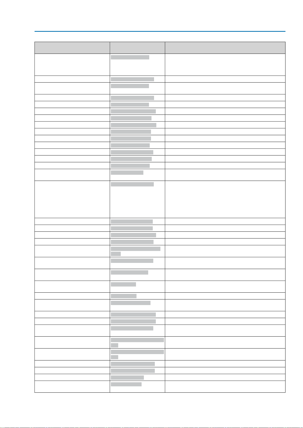
3.6.2. Settable (user definable) signals
Table 2: Description of the parameter settings
Prm-Text-Def GSD file
(1) = "Bit: End p. CLOSED"
(2) = "Bit: End p. OPEN"
(3) = "Bit: End p. CLOSED, blink"
(4) = "Bit: End p. OPEN, blink"
(5) = "Bit: Setpoint reached"
(6) = "Bit: Running CLOSE"
(7) = "Bit: Running OPEN"
(8) = "Bit: Selector sw. LOCAL"
(9) = "Bit: Sel. sw. REMOTE"
(10) = "Bit: Sel. sw. OFF"
(11) = "Bit: Limit sw. CLOSED"
(12) = "Bit: Limit sw. OPEN"
(13) = "Bit:Torque sw. CLOSE"
(14) = "Bit:Torque sw. OPEN"
(15) = "Bit: Device ok"
(16) = "Bit: Failure"
(17) = "Bit: Function check"
(18) = "Bit: Out of spec."
(19) = "Bit: Maintenance requ."
(process representation)
–(0) = "Bit: Reserved"
Bit: End p. CLOSED
Bit: End p. OPEN
Bit: EP CLOSED, blink
Bit: EP OPEN, blink
Bit: Setpoint reached
Bit: Running CLOSE
Bit: Running OPEN
Bit: Sel. sw. LOCAL
Bit: Sel. sw. REMOTE
Bit: Sel. sw. OFF
Bit: Limit sw. CLOSED
Bit: Limit sw. OPEN
Bit: Torque sw.CLOSE
Bit: Torque sw.OPEN
Bit: Device ok
Bit: Failure
Bit: Function check
Bit: Out of spec.
Bit: Maintenance requ.
DescriptionDesignation
For limit seating: Limit switch operated in direction CLOSE
For torque seating:Torque switch and limit switch operated
in direction CLOSE
For limit seating: Limit switch operated in direction OPEN
For torque seating:Torque switch and limit switch operated
in direction OPEN
End position CLOSED reached or intermediate position
reached
(The intermediate position is only indicated if parameter
Signal interm. pos. M0167 = OPEN/CLOSED = On.)
Signal blinking: Actuator runs in direction CLOSE.
End position OPEN reached or intermediate position
reached.
(The intermediate position is only indicated if parameter
Signal interm. pos. M0167 = OPEN/CLOSED = On.)
Signal blinking: Actuator runs in direction OPEN.
The position setpoint is is within max. error variable (outer
dead band). Is only signalled if Profibus DP master has set
the Fieldbus SETPOINT bit (process representation output).
An operation command in direction CLOSE is performed
via fieldbus:Fieldbus CLOSE or Fieldbus SETPOINT (process representation output).This bit remains also set during
operation pauses (e.g. due to the dead time or the rev ersing
prevention time).
An operation command in direction OPEN is performed via
fieldbus:Fieldbus OPEN or Fieldbus SETPOINT (process
representation output).This bit remains also set during operation pauses (e.g. due to the dead time or the reversing
prevention time).
Selector switch is in position LOCAL.
Selector switch is in position REMOTE.
Selector switch is in position OFF.
Limit switch operated in end position CLOSED
Limit switch operated in end position OPEN
Torque switch operated in direction CLOSE
Torque switch operated in direction OPEN
Collective signal 05:
The device is ready for remote control.
No AUMA warnings, AUMA faults or signals according to
NAMUR are present.
Collective signal 10:
Indication according to NAMUR recommendation NE 107
Actuator function failure, output signals are invalid.
Collective signal 08:
Indication according to NAMUR recommendation NE 107
The actuator is being worked on; output signals are temporarily invalid.
Collective signal 07:
Indication according to NAMUR recommendation NE 107
Actuator is operated outside the normal operation conditions.
Collective signal 09:
Indication according to NAMUR recommendation NE 107
Recommendation to perform maintenance.
12
Actuator controls
AC 01.2/ACExC 01.2 Profibus DP Commissioning
Prm-Text-Def GSD file
(20) = "Bit: Fault"
(21) = "Bit:Warnings"
(22) = "Bit: Not ready REMOTE"
(23) = "Bit: Op. pause active"
(24) = "Bit: Start step mode"
(25) = "Bit: Actuator running"
(26) = "Bit: Running LOCAL"
(27) = "Bit: Running REMOTE"
(28) = "Bit: Running via handw."
(29) = "Bit: In interm. position"
(30) = "Bit: Failure behav. active"
(31) = "Bit: Intermediate pos. 1"
(32) = "Bit: Intermediate pos. 2"
(33) = "Bit: Intermediate pos. 3"
(34) = "Bit: Intermediate pos. 4"
(35) = "Bit: Intermediate pos. 5"
(36) = "Bit: Intermediate pos. 6"
(37) = "Bit: Intermediate pos. 7"
(38) = "Bit: Intermediate pos. 8"
(39) = "Bit: Input DIN 1"
(40) = "Bit: Input DIN 2"
(41) = "Bit: Input DIN 3"
(42) = "Bit: Input DIN 4"
(43) = "Bit: Input DIN 5"
(44) = "Bit: Input DIN 6"
(45) = "Bit: Input DIN 7"
(46) = "Bit: Input DIN 8"
(47) = "Bit: FailState fieldbus"
(48) = "Bit: I/O interface"
(49) = "Bit: EMCY behav.act."
(50) = "Bit: EMCY stop active"
(51) = "Bit: Service active"
(52) = "Bit: Interlock active"
(53) = "Bit: Sel. sw. not REMOTE"
(54) = "Bit: Handwheel active"
(process representation)
Bit: Fault
Bit: Warnings
Bit: Not ready REMOTE
Bit: Op. pause active
Bit: Start step mode
Bit: Actuator running
Bit: Running LOCAL
Bit: Running REMOTE
Bit: Handwheel oper.
Bit: In interm. position
Bit: Failure behav. act.
Bit: Interm. pos. 1
Bit: Interm. pos. 2
Bit: Interm. pos. 3
Bit: Interm. pos. 4
Bit: Interm. pos. 5
Bit: Interm. pos. 6
Bit: Interm. pos. 7
Bit: Interm. pos. 8
Bit: Input DIN 1
Bit: Input DIN 2
Bit: Input DIN 3
Bit: Input DIN 4
Bit: Input DIN 5
Bit: Input DIN 6
Bit: Input DIN 7
Bit: Input DIN 8
Bit: FailState fieldbus
Bit: I/O interface
Bit: EMCY behav. act.
Bit: EMCY stop active
Bit: Service active
Bit: Interlock active
Bit: Sel. sw. not REMOTE
Bit: Handwheel active
DescriptionDesignation
Collective signal 03:
Contains the result of a disjunction (OR operation) of all
faults.
The actuator cannot be operated.
Collective signal 02:
Contains the result of an OR disjunction of all warnings.
Collective signal 04:
Contains the result of a disjunction (OR-operation) of the
signals, forming the "Not ready REMOTE" group.
The actuator cannot be operated from REMOTE.
The actuator is in off-time (e.g. stepping mode or reversing
prevention time).
The actuator is within the set stepping range.
Actuator is running (output drive is moving)
Hard wired collective signal consisting of signals:
●
(26) Bit: Running LOCAL
●
(27) Bit: Running REMOTE
●
(28) Bit: Handwheel oper.
Output drive rotates due to operation command from LOCAL.
Output drive rotates due to operation command from RE-
MOTE.
Output drive rotates without electric operation command
(manual operation).
The actuator is in an intermediate position e.g. neither in
end position OPEN nor in end position CLOSED.
The failure behaviour is active.
Intermediate position 1 reached
Intermediate position 2 reached
Intermediate position 3 reached
Intermediate position 4 reached
Intermediate position 5 reached
Intermediate position 6 reached
Intermediate position 7 reached
Intermediate position 8 reached
A high signal (+24 V DC) is present at digital input 1.
A high signal (+24 V DC) is present at digital input 2.
A high signal (+24 V DC) is present at digital input 3.
A high signal (+24 V DC) is present at digital input 4.
A high signal (+24 V DC) is present at digital input 5.
A high signal (+24 V DC) is present at digital input 6.
Parameter not available
Parameter not available
No valid communication via fieldbus (despite a vailab le con-
nection)
The actuator is controlled via the I/O interface (parallel).
Operation mode EMERGENCY is active (EMERGENCY
signal was sent).
Operation mode EMERGENCY stop is active (EMERGENCY
stop button pressed).
Operation mode Service (via Bluetooth) is active.
Actuator is interlocked.
Selector switch is in position Local control (LOCAL) or 0
(OFF).
Manual operation is active (handwheel is engaged); optional
signal
13
Actuator controls
Commissioning AC 01.2/ACExC 01.2 Profibus DP
Prm-Text-Def GSD file
(55) = "Bit:Wrong command"
(56) = "Bit:Thermal fault"
(57) = "Bit: Phase fault"
(58) = "Bit:Wrong phase sequence"
(59) = "Bit: Mains quality"
(60) = "Bit:Torque fault CLOSE"
(61) = "Bit:Torque fault OPEN"
(62) = "Bit:Torque fault"
(63) = "Bit: Operat. time warning"
(64) = "Bit: On time warning"
(65) = "Bit: 24 V AC, internal"
(66) = "Bit: 24 V DC control volt."
(67) = "Bit: 24 V DC, internal"
(68) = "Bit: 24 V DC, external"
(69) = "Bit: Internal error"
(70) = "Bit: Internal warning"
(71) = "Bit: No reaction"
(72) = "Bit: Configuration error"
(73) = "Bit:Temp. fault controls"
(74) = "Bit:Temp. fault motor"
(75) = "Bit:Temp.fault gearbox"
(76) = "Bit:Wrn heater"
(77) = "Bit: RTC not set"
(78) = "Bit:Wrn humidity"
(79) = "Bit:WrnRefActPos"
(80) = "Bit:WrnSigRgeActPos"
(81) = "Bit:WrnSigLossActPos"
(82) = "Bit:WrnActPosition"
(process representation)
Bit: Setpoint disabled
Bit: Thermal fault
Bit: Phase failure
Bit: Incorrect phase seq
Bit: Mains quality
Bit: Torque fault CLOSE
Bit: Torque fault OPEN
Bit: Torque fault
Bit: Op. time warning
Bit: On time warning
Bit: 24 V AC internal
Bit: 24 V DC control volt.
Bit: 24 V DC internal
Bit: 24 V DC, external
Bit: Internal error
Bit: Internal warning
Bit: No reaction
Bit: Configuration error
Bit: Temp. fault controls
Bit: Temp. fault motor
Bit: Temp. fault gear
Bit: Wrn heater
Bit: RTC not set
Bit: Wrn humidity
Bit: WrnRefActPos
Bit: WrnSigRgeActPos
Bit: WrnSigLossActPos
Bit: WrnActPosition
DescriptionDesignation
Received setpoint cannot be performed as the positioner is
not available.
Motor protection tripped.
●
When connecting to a 3-ph AC system and with internal
24 V DC supply of the electronics: Phase 2 is missing.
●
When connecting to a 3-ph or 1-ph AC system and with
external 24 V DC supply of the electronics: One of the
phases L1, L2 or L3 is missing.
The phase conductors L1, L2 and L3 are connected in the
wrong sequence.
Due to insufficient mains quality, the controls cannot detect
the phase sequence (sequence of phase conductors L1, L2
and L3) within the pre-set time frame provided for monitoring.
Torque fault in direction CLOSE
Torque fault in direction OPEN
Torque fault in directions CLOSE or OPEN
Warning: Max. permissible operating time for an operation
(OPEN-CLOSE) exceeded
Warning: Max. number of motor starts (starts) or max. run-
ning time/h exceeded
The internal 24 V AC v oltage supply of the controls has ex-
ceeded the power supply limits.
The 24 V A C v oltage supply is used to control the re v ersing
contactors, to assess the thermoswitches, to supply the internal actuator heater and, as an option, to generate the 115
V AC supply for the customer.
The 24 V DC auxiliary voltage (e.g. for supply of the control
outputs) is outside the supply voltage limits.
The internal 24 V DC supply voltage of the controls for
supply of the electronic components is outside the supply
voltage limits.
The external 24 V DC voltage supply of the controls has
exceeded the power supply limits.
Collective signal 14: Internal error
Collective signal 15: Internal warning
No actuator reaction to operation commands within the set
reaction time.
Incorrect configuration, i.e. the current setting is invalid.
Parameter not available
Parameter not available
Parameter not available
Heater failure at actuator (control unit)
Real time clock has not yet been set.
Parameter not available
Warning:
Position feedback of actuator was not yet referenced for
limit end positions.
Warning:
Current position feedback signal range is outside the permissible range.
Warning:
A signal loss has occurred for actuator position feedback.
Warning: Actual position of actuator
Collective signal consisting of:
●
(79) Bit: WrnRefActPos
●
(80) Bit: WrnSigRgeActPos
●
(81) Bit: WrnSigLossActPos
14
Actuator controls
AC 01.2/ACExC 01.2 Profibus DP Commissioning
Prm-Text-Def GSD file
(83) = "Bit:Wrn FO ring"
(84) = "Bit:WrnOnTiRunning"
(85) = "Bit:WrnOnTiStarts"
(86) = "Bit:Wrn vibration"
(87) = "Bit:Wrn dew point"
(88) = "Bit:WrnControlsTemp"
(89) = "Bit:Wrn motor temp."
(90) = "Bit:Wrn gearbox temp."
(91) = "Bit:Wrn input AIN 1"
(92) = "Bit:Wrn input AIN 2"
(93) = "Bit:WrnActProcVal"
(94) = "Bit:WrnProcSetpoint"
(95) = "Bit:WrnSetpointPos"
(96) = "Bit: Fieldbus failure"
(97) = "Bit: Local Stop"
(98) = "Bit:Wrong operation cmd"
(99) = "Bit: Channel 1 active"
(100) = "Bit: Channel 2 active"
(101) = "Bit: Motor running Close"
(102) = "Bit: Motor running Open"
(103) = "Bit:Time Sync active"
(104) = "Bit: Interlock Remote"
(105) = "Bit: Interlock Local"
(106) = "Bit: Interlock"
(107) = "Bit: Disabled"
(108) = "Bit: Config.Warning"
(109) = "Bit: Pb DataEx Ch1"
(110) = "Bit: Pb DataEx Ch2"
(111) = "Bit:Wrn FOC budget"
(112) = "Bit: FieldbusFailsafeAct.1"
(113) = "Bit: FieldbusFailsafeAct.2"
(114) = "Bit: Chan1 BusComm"
(115) = "Bit: Chan2 BusComm"
(116) = "Bit: PVST active"
(117) = "Bit: PVST fault"
(process representation)
Bit: Wrn FO cables
Bit: WrnOnTiRunning
Bit: WrnOnTiStarts
Bit: WrnOnTiRunning
Bit: WrnOnTiStarts
Bit: Wrn controls temp
Bit: Wrn motor temp
Bit: Wrn gearbox temp
Bit: Wrn input AIN 1
Bit: Wrn input AIN 2
Bit: WrnActProcVal
Bit: WrnProcSetpoint
Bit: WrnSetpointPos
Bit: Fieldbus failure
Bit: Local STOP
Bit: Wrong oper. cmd
Bit: Channel 1 active
Bit: Channel 2 active
Bit:Motor runs CLOSE
Bit:Motor runs OPEN
Bit: DP TimeSynch (Set-
Prm)
Bit: Interlock Remote
Bit: Interlock Local
Bit: Interlock
Bit: Disabled
Bit: Config. warning
Bit: Channel 1 DataEx
Bit: Channel 2 DataEx
Bit: Wrn FOC budget
Bit: Chan 1 FailState fieldbus
Bit: Chan 2 FailState fieldbus
Bit: Channel 1 activity
Bit: Channel 2 activity
Bit: PVST active
Bit: PVST error
DescriptionDesignation
Warning:
Optical receiving signal (channel 1) incorrect (no or insufficient Rx receive level) or RS-485 format error (incorrect
bit(s))
Warning on time max. running time/h exceeded
Warning on time max. number of motor starts (starts) ex-
ceeded
Parameter not available
Parameter not available
Warning:Temperature within controls housing too high
Parameter not available
Parameter not available
Warning: Loss of signal analogue input 1
Warning: Loss of signal analogue input 2
Warning: Loss of signal actual process value
Warning: Loss of signal process setpoint
Warning: Loss of signal of actuator setpoint position
Fieldbus failure
A local STOP is active.
Push button STOP of local controls is operated.
Wrong operation command
Indicates that several operation commands were received
simultaneously via Profibus DP (e.g. Remote OPEN and
Remote CLOSE simultaneously or Remote CLOSE/Remote
OPEN and Remote SETPOINT simultaneously) or that the
max. value for a setpoint position has been exceeded (setpoint position > 1,000).
Channel 1 is the active operation command channel.
Channel 2 is the active operation command channel.
Motor runs in direction CLOSE.
Motor runs in direction OPEN.
Time synchronisation is active.
The Interlock function prevents an operation in operation
mode REMOTE.
The Interlock function prevents an operation in operation
mode LOCAL.
The Interlock function prevents an operation in operation
mode REMOTE or in operation mode LOCAL.
Operation mode disabled.
Warning: Configuration setting is incorrect.
The device can still be operated with restrictions.
Channel 1 is in the data exchange state (DataEx).
Channel 2 is in the data exchange state (DataEx).
Warning: FO cable system reserve reached (critical or per-
missible Rx receive level)
No valid fieldbus communication via channel 1 (application
does not communicate with the DCS).
No valid fieldbus communication via channel 2 (application
does not communicate with the DCS).
Bus communication available on channel 1.
Bus communication available on channel 2.
Partial Valve Stroke Test (PVST) is active.
Partial Valve Stroke Test (PVST) could not be successfully
completed.
15

Actuator controls
Commissioning AC 01.2/ACExC 01.2 Profibus DP
Prm-Text-Def GSD file
(118) = "Bit: PVST abort"
(119) = "Bit: Interlock OPEN"
(120) = "Bit: Interlock CLOSE"
(121) = "Bit: Bypass Interlock"
(122) = "Bit: Fault no reaction"
(123) = "Bit: Config error remote"
(124) = "Bit:Torque wrn OPEN"
(125) = "Bit:Torque wrn CLOSE"
(126) = "Bit: RTC button cell"
(127) = "Bit:Wrn FOC connection"
(128) = "u16: Actual position"
(129) = "u16: Input AIN 1"
(130) = "u16: Input AIN 2"
(131) = "u16:Torque CLOSE %"
(132) = "u16:Torque OPEN %"
(133) = "u16:Torque CLOSE Nm"
(134) = "u16:Torque OPEN Nm"
(135) = "u16: torque CLOSE ft-lb"
(136) = "u16:Torque OPEN ft-lb"
(137) = "u16:Torque"
(139) = "u16: Actual P osition 0-100%"
(process representation)
Bit: PVST abort
Bit: Interlock OPEN
Bit: Interlock CLOSE
Bit: Interlock by-pass
Bit: No reaction (fault)
Bit: Config. error REMOTE
Bit: Torque warn. OPEN
Bit: Torque warn. CLOSE
Bit: RTC button cell
Bit: Wrn FOC connection
u16: Actual position
u16: Input AIN 1
u16: Input AIN 2
u16: Torque CLOSE %
u16: Torque OPEN %
u16: Torque CLOSE Nm
u16: Torque OPEN Nm
u16: torque CLOSE ft-lb
u16: Torque OPEN ft-lb
u16: Torque
Actual position 0-100 %
DescriptionDesignation
Partial Valve Stroke Test (PVST) was aborted or could not
be started. Remedy: Perform RESET or restart PVST.
Release signal OPEN not active: Operation commands in
direction OPEN are disabled.
Release signal CLOSE not active: Operation commands in
direction CLOSE are disabled.
Bypass of interlock function is active.
No reaction detected at actuator output drive.
Config. error of REMOTE interface active.
Warning: Limit value for torque warning in direction OPEN
exceeded.
Warning: Limit v alue f or torque w arning in direction CLOSE
exceeded.
Warning:Voltage of RTC button cell too low.
Warning: FO cable connection is not available.
Actual actuator position (0 – 1,000 per mil)
Analogue input 1
Analogue input 2
Torque in direction CLOSE, unit in %
Torque in direction OPEN, unit in %
Torque in direction CLOSE, unit in Nm
Torque in direction OPEN, unit in Nm
Torque in direction CLOSE, unit in ft-lb
Torque in direction OPEN, unit in ft-lb
Actual torque value
Actual actuator position (0 – 100 percent)
(201) = "Cylinder printing max."
(202) = "Hydraulics fault"
(203) = "Hydraulics warning"
(204) = "Safe ESD"
(205) = "Safe Stop"
(206) = "SIL fault"
(207) = "SIL function active"
(208) = "PVST required"
(209) = "Mechanic lifetime"
Bit: Cylinder pressure max.
Bit: Hydraulic pressure
fault
Bit: Wrn hydraulics
Bit: Safe ESD
Bit: Safe STOP
Bit: SIL fault
Bit: SIL function active
1)
1)
1)
1)
Bit: PVST required
Bit: Maintenance mechan-
ics
Parameter not available(160) = "i16: Actual position"
Parameter not available(161) = "i16: Input AIN 1"
Parameter not available(162) = "i16: Input AIN 2"
Parameter not available(163) = "i16:Torque CLOSE %"
Parameter not available(164) = "i16:Torque OPEN %"
Parameter not available(192) = "float: Actual position"
Parameter not available(193) = "float: Input AIN 1"
Parameter not available(194) = "float: Input AIN 2"
Parameter not available(195) = "float:T CLOSE %"
Parameter not available(196) = "float:T OPEN %"
Parameter not available(197) = "float:T CLOSE Nm"
Parameter not available(198) = "float:T OPEN Nm"
Parameter not available(199) = "float:T CLOSE lbs/ft."
Parameter not available(200) = "float:T OPEN lbs/ft."
Parameter not available
Parameter not available
Parameter not available
Safe ESD function (Emergency Shut Down) is active.
Safe STOP function is active.
A SIL fault has occurred (collective signal).
A SIL function is active.
(PVST) Partial Valve Stroke Test should be executed
Mechanic maintenance requirement
16
Actuator controls
AC 01.2/ACExC 01.2 Profibus DP Commissioning
Prm-Text-Def GSD file
(210) = "Seal lifetime"
(211) = "Seal lifetime"
(212) = "Contactor lifetime"
(213) = "Maintenance interval"
(214) = "Maintenance required"
The safety function indications via fieldbus are for information only and must not be used as part of a safety function.The I/O signals of
1)
the SIL module must be used for this purpose.
(process representation)
Bit: Maintenance seals
Bit: Maintenance lubricant
Bit: Maintenance contact-
ors
Bit: Maintenance interval
Bit: Maintenance required
DescriptionDesignation
Seal maintenance requirement
Lubricant maintenance requirement
Contactor maintenance requirement
The set maintenance interval has expired.
Maintenance required
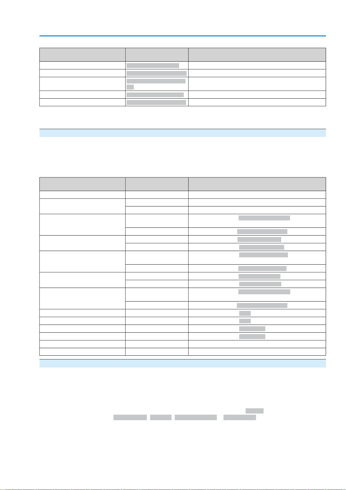
3.6.3. Additional (user-definable) parameters (option)
Parameter description of additional user parameters for setting the time stamp and
alarms according to Profibus DP-V2, available with the optional version
AUMA0CBD.gsd.
Table 3: Description of additional settings
ExtUserPrmData =
Text(0) = "disable"3 "TS -> End Position Close"
Text(1) = "enable"
Text(0) = "disable"4 "TS -> End Position Open"
Text(1) = "enable"
Text(0) = "disable"5 "TS -> Torque Limit Switch Close"
Text(1) = "enable"
Text(0) = "disable"6 "TS -> Torque Limit Switch Open"
Text(1) = "enable"
Text(0) = "disable"7 "TS -> Ready and Remote"
Text(1) = "enable"
Text(0) = "disable"8 "TS -> Fault"
Text(1) = "enable"
Text(0) = "disable"9 "TS -> Power Supply Fault"
Text(1) = "enable"
DescriptionSettingPrm-Text GSD Datei
No function–1 "Setpoint valid bit"
DP-V2 time stamp deactivated.Text(0) = "disable"2 "Timestamp (TS)"
DP-V2 time stamp activated.Text(1) = "enable"
DP-V2 time stamp of End position CLOSED signal deactiv-
ated.
DP-V2 time stamp of End position CLOSED signal activated.
DP-V2 time stamp of End position OPEN signal deactivated.
DP-V2 time stamp of End position OPEN signal activated.
DP-V2 time stamp of Torque sw. CLOSED signal deactiv-
ated.
DP-V2 time stamp of Torque sw. CLOSED signal activated.
DP-V2 time stamp of Torque sw. OPEN signal deactivated.
DP-V2 time stamp of Torque sw. OPEN signal activated.
DP-V2 time stamp of Selector sw. REMOTE signal deactiv-
ated.
DP-V2 time stamp of Selector sw. REMOTE signal activated.
DP-V2 time stamp of Fault signal deactivated.
DP-V2 time stamp of Fault signal activated.
DP-V2 time stamp of Phase fault signal deactivated.
DP-V2 time stamp of Phase fault signal activated.
Without function (reserved)–10 "TS -> reserved"
Without function (reserved)–11 "reserved Byte"
3.6.4. Further adaptation options
From firmware 04.05.xx, the actuator controls provide the option to adapt to the
existing DCS configurations of the actuator type range A C 01.1/ACExC 01.1. Actuator
controls of type range AC 01.2/A CExC 01.2 can be adapted as to support the default
arrangement of the Profibus DP-V0 process representation input of
AC 01.1/ACExC 01.1 without changing the Profibus configuration of the DCS.
Setting is performed using the following parameter:Device
configuration>Profibus>Connection type = AUMATIC .1
17

Actuator controls
Commissioning AC 01.2/ACExC 01.2 Profibus DP
●
Information
Only the Profibus DP-V0 standard arrangement of the process representation
input of AC 01.1/ACExC 01.1 is supported, deviating arrangements of the
Profibus DP-V0 process data input require use/installation of AUMA04CF.gsd
or AUMA0CBD.gsd file in the DCS.
●
With connection type = AUMATIC.1 the AC 01.2/A CExC 01.2 does not provide
any diagnostic NAMUR NE 107 information within the cyclic process data representation.
●
EDD or DTM of the AC 01.2/ACExC 01.2 m ust imperativ ely be used f or acyclic
communication via Profibus DP-V1 with AC 01.2/ACExC 01.2!
●
Factory setting:Connection type = AUMATIC.2
3.7. Communication monitoring
3.7.1. Connection monitoring of the Profibus DP communication
The connection monitoring within the master has to be activated to monitor both
master and cable connection between master and actuator (parameter telegram
byte 1, bit 3, WD_ON = 1).
Only if the connection monitoring is active can the actuator react in the even of loss
of communication once the monitoring time also set in the master has elapsed.
The reaction of the actuator also depends on the settings for failure behaviour or
EMERGENCY BEHAVIOUR.
3.7.2. Fail Safe and Global Control Clear telegrams
Another possibility to set the slave to a safe state in the event of a fault are the fail
safe telegrams (telegr ams with data length = 0). If fails safe telegrams are received,
the actuator remains in the DataExchange state; depending on the respectiv e setting,
the actuator may initiate the failure behaviour or the EMERGENCY behaviour.The
actuator quits the Fail Safe state as soon as valid telegrams with the data length ≠
0 are received.
Furthermore, the Global Control Clear (GC Clear) master telegrams can also be
used to initiate the failure behaviour or the EMERGENCY behaviour.This state can
be disabled using a Global Control Operate telegram (GC Operate).
For activated EMERGENCY behaviour:
The actuator can start its operation due to an EMERGENCY signal or a loss
of communication.
Risk of personal injuries or damage to the valve.
→
For commissioning and maintenance work: Set selector switch to position 0
(OFF).The motor operation can only be interrupted in this selector switch position.
→
If the actuator starts its operation by accident: Set selector switch to position 0
(OFF).
3.8. I & M functions
18
The actuator controls support the I & M functions according to PNO guideline 3.502.
With the term Identification & Maintenance (I & M) functions, the Profibus user
organisation e.V. (PNO) introduced a new functionality for all Profibus devices with
acyclic communication channel that may prove very useful for plant operators.The
I & M functions define how certain device-describing data (according to name plate)
is to be uniformly stored in the Profibus devices. Engineering tools may then read
and inteprete the data according to a code which can be accessed on the PNO
server.This provides uniform and powerful access to all important and current device
data, one of the major requirements for asset management.
Part of the device-specific I & M information is the unambiguous asset identification
using a manufacturer ID (MANUFACTURER_ID, for AUMA actuators = 319), the

Actuator controls
AC 01.2/ACExC 01.2 Profibus DP Commissioning
order number (ORDER_ID) of the actuator as well as the individual serial number
(SERIAL_NUMBER). Further data supplements the asset information.
SizeContent
Header
10 OctetsManufacturer specific
I & M Block
2 OctetsMANUFACTURER_ID
20 OctetsORDER_ID
16 OctetsSERIAL_NUMBER
2 OctetsHARDWARE_REVISION
4 OctetsSOFTWARE_REVISION
2 OctetsREVISION_COUNTER
2 OctetsPROFILE_ID
2 OctetsPROFILE_SPECIFIC_TYPE
2 OctetsIM_VERSION
2 OctetsIM_SUPPORTED
19
Actuator controls
Description of the data interface AC 01.2/ACExC 01.2 Profibus DP
4. Description of the data interface
4.1. Input data (process representation input) – signals
The process representation input allows the master (controls) to read the state of
the slave (actuator).
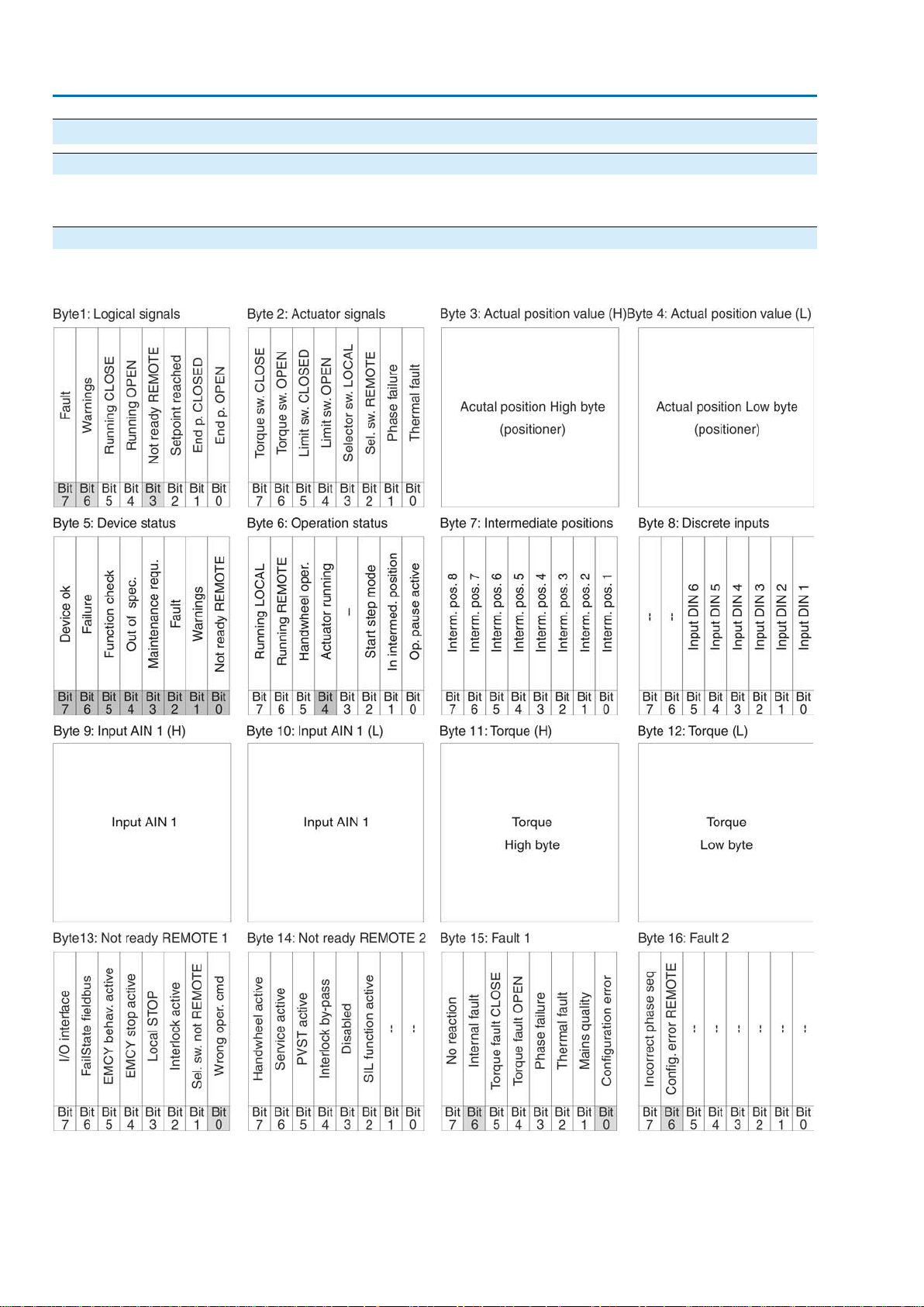
4.1.1. Process representation input (default process representation)
Grey bits are collective signals.They contain the results of a disjunction (OR
operation) of other information.
20
Actuator controls
AC 01.2/ACExC 01.2 Profibus DP Description of the data interface
21

Actuator controls
Description of the data interface AC 01.2/ACExC 01.2 Profibus DP
4.1.2. Description of the bytes in the process representation input Byte 1: Logical signals
Bits 3, 6, and 7 are collective signals.
Bits 5 and 4 of the logical signals (byte1) indicate a logical operation of the actuator ,
i.e. they are set when the actuator has received the command to perf orm an electrical
operation (also active when e.g. the actuator is in a stepping pause during stepping
mode or waiting for the end of the dead time).
Table 4: Byte 1: Logical signals
Bit
(process representation)
0
Bit: End p. OPEN
1
Bit: End p. CLOSED
2
Bit: Setpoint reached
3
Bit: Not ready REMOTE
4
Bit: Running OPEN
5
Bit: Running CLOSE
6
Bit: Warnings
7
Bit: Fault
MOTE"
DescriptionValuePrm-Text-Def GSD fileDesignation
For limit seating: Limit switch operated in direction OPEN
1(2) = "Bit: End p. OPEN"
For torque seating:Torque switch and limit switch operated in direction OPEN
No signal0
For limit seating: Limit switch operated in direction
1(1) = "Bit End p. CLOSED"
CLOSE
For torque seating:Torque switch and limit switch operated in direction CLOSE
No signal0
The setpoint is within max. error variable (outer dead
1(5) = "Bit: Setpoint reached"
band). Is only signalled if Profibus DP master has set
the Fieldbus SETPOINT bit (process representation
output).
No signal0
Collective signal 04:
1(22) = "Bit: Not ready RE-
Contains the result of a disjunction (OR-operation) of all
bits comprised in bytes 13 and 14 (Not ready REMOTE
1 and Not ready REMOTE 2).
The actuator cannot be operated from REMOTE.
The actuator can only be operated via the local controls.
In bytes 13 and 14, no signals are active (all bits are set
0
to 0).
An operation command in direction OPEN is performed
1(7) = "Bit: Running OPEN"
via fieldbus:Fieldbus OPEN or Fieldbus SETPOINT
(process representation output).This bit remains also
set during operation pauses (e.g. due to the dead time
or the reversing prevention time).
Operation in direction OPEN via fieldbus is not ex ecuted.0
An operation command in direction CLOSE is performed
1(6) = "Bit: Running CLOSE"
via fieldbus:Fieldbus CLOSE or Fieldbus SETPOINT
(process representation output).This bit remains also
set during operation pauses (e.g. due to the dead time
or the reversing prevention time).
Operation in direction CLOSE via fieldbus is not ex-
0
ecuted.
Collective signal 02:
1(21) = "Bit:Warnings"
Contains the result of a disjunction (OR-operation) of all
bits of bytes 17 to 20 (Warning 1 to Warning 4).
In bytes 17 and 20, no warnings are active (all bits are
0
set to 0).
Collective signal 03:
1(20) = "Bit: Fault"
Contains the result of a disjunction (OR-operation) of all
bits of bytes 15 and 16 (Fault 1 and Fault 2).
The actuator cannot be operated.
In bytes 15 and 16, no faults are active (all bits are set
0
to 0).
22
Actuator controls
AC 01.2/ACExC 01.2 Profibus DP Description of the data interface
Byte 2: Actuator signals
Table 5: Byte 2: Actuator signals
Bit
(process representation)
0
Bit: Thermal fault
1
Bit: Phase failure
2
Bit: Sel. sw. REMOTE
3
Bit: Sel. sw. LOCAL
4
Bit: Limit sw. OPEN
5
Bit: Limit sw. CLOSED
6
Bit: Torque sw.OPEN
7
Bit: Torque sw.CLOSE
MOTE"
LOCAL"
CLOSED"
OPEN"
CLOSE"
DescriptionValuePrm-Text-Def GSD fileDesignation
Motor protection tripped1(56) = "Bit:Thermal fault"
No signal0
●
1(57) = "Bit: Phase fault"
When connecting to a 3-ph AC system and with internal 24 V DC supply of the electronics: Phase 2 is
missing.
●
When connecting to a 3-ph or 1-ph AC system and
with external 24 V DC supply of the electronics: One
of the phases L1, L2 or L3 is missing.
All phases are available.0
Selector switch is in position REMOTE.1(9) = "Bit: Sel. sw. RESelector switch is not in position REMOTE.0
Selector switch is in position LOCAL.1(8) = "Bit: Selector sw.
Selector switch is not in position LOCAL.0
Limit switch operated in end position OPEN1(12) = "Bit: Limit sw. OPEN"
No signal0
Limit switch operated in end position CLOSED1(11) = "Bit: Limit sw.
No signal0
Torque switch operated in direction OPEN.1(14) = "Bit:Torque sw.
No signal0
Torque switch operated in direction CLOSE.1(13) = "Bit:Torque sw.
No signal0
Table 6: Byte 5: Device status
Bit
(process representation)
0
Bit: Not ready REMOTE
1
Bit: Warnings
2
Bit: Fault
Bytes 3 and 4: Actual position
Byte 3 = high byte, byte 4 = low byte.
If a position transmitter (potentiometer, RWG, EWG, or MWG) is installed in the
actuator, b ytes 3 and 4 are used to tr ansmit the current actuator position.The value
is transmitted in per mil (value: 0 – 1,000).
Byte 5: Device status
DescriptionValuePrm-Text-Def GSD fileDesignation
Collective signal 04:
1(22) = "Bit: Not ready RE-
MOTE"
Contains the result of a disjunction (OR-operation) of all
bits comprised in bytes 13 and 14 (Not ready REMOTE
1 and Not ready REMOTE 2).
The actuator cannot be operated from REMOTE.
The actuator can only be operated via the local controls.
In bytes 13 and 14, no signals are active (all bits are set
0
to 0).
Collective signal 02:
1(21) = "Bit:Warnings"
Contains the result of a disjunction (OR-operation) of all
bits of bytes 17 to 20 (Warning 1 to Warning 4).
In bytes 17 and 20, no warnings are active (all bits are
0
set to 0).
Collective signal 03:
1(20) = "Bit: Fault"
Contains the result of a disjunction (OR-operation) of all
bits of bytes 15 and 16 (Fault 1 and Fault 2).
The actuator cannot be operated.
In bytes 15 and 16, no faults are activ e (all bits are set to
0
0).
23

Actuator controls
Description of the data interface AC 01.2/ACExC 01.2 Profibus DP
Bit
(process representation)
3
Bit: Maintenance requ.
4
Bit: Out of spec.
5
Bit: Function check
6
Bit: Failure
7
Bit: Device ok
requ."
DescriptionValuePrm-Text-Def GSD fileDesignation
Collective signal 09:
1(19) = "Bit: Maintenance
Indication according to NAMUR recommendation NE 107
Recommendation to perform maintenance.
Contains the result of a disjunction (OR-operation) of all
bits of byte 24 (Maintenance required).
In all bits of byte 24, no signals are active (all bits are set
0
to 0).
Collective signal 07:
1(18) = "Bit: Out of spec."
Indication according to NAMUR recommendation NE 107
Actuator is operated outside the normal operation conditions.
Contains the result of a disjunction (OR-operation) of all
bits of bytes 25 to 28 (Out of specification 1 to 4).
In bytes 25 and 28, no signals are active (all bits are set
0
to 0).
Collective signal 08:
1(17) = "Bit: Function check"
Indication according to NAMUR recommendation NE 107
The actuator is being worked on; output signals are temporarily invalid.
Contains the result of a disjunction (OR-operation) of all
bits of bytes 29 and 30 (Function check 1 and 2).
In bytes 29 and 30, no signals are active (all bits are set
0
to 0).
Collective signal 10:
1(16) = "Bit: Failure"
Indication according to NAMUR recommendation NE 107
Actuator function failure, output signals are invalid.
Contains the result of a disjunction (OR-operation) of all
bits of byte 23 (Failure).
In all bits of byte 23, no signals are active (all bits are set
0
to 0).
Sammelmeldung 05:
1(15) = "Bit: Device ok"
The device is ready for remote control.
No AUMA warnings, AUMA faults or signals according to
NAMUR are present.
Bit 7 is set if bits 0 to 6 are deleted.
Contains the result of a disjunction (OR-operation) of bits
0
0 to 6 (device status).
Byte 6: Operation status
This byte stores information about actuator movement.
Table 7: Byte 6: Operation status
Bit
(process representation)
0
Bit: Op. pause active
1
Bit: In interm. position
2
Bit: Start step mode
4
Bit: Actuator running
ive"
tion"
mode"
ning"
DescriptionValuePrm-Text-Def GSD fileDesignation
The actuator is in off-time (e.g. rev ersing prevention time)1(23) = "Bit: Op. pause actNo signal0
The actuator is in an intermediate position e.g. neither in
1(29) = "Bit: In interm. posi-
end position OPEN nor in end position CLOSED.
No signal0
The actuator is within the set stepping range.1(24) = "Bit: Start step
The actuator is outside the set stepping range.0
No signal (reserved)——3
Actuator is running (output drive is moving)
1(25) = "Bit: Actuator run-
Hard wired collective signal consisting of signals:
●
(26) Bit: Running LOCAL
●
(27) Bit: Running REMOTE
●
(28) Bit: Handwheel oper.
No signal0
24
Actuator controls
AC 01.2/ACExC 01.2 Profibus DP Description of the data interface
Bit
(process representation)
5
Bit: Handwheel oper.
6
Bit: Running REMOTE
7
Bit: Running LOCAL
handw."
MOTE"
AL"
Byte 7: Intermediate positions
Table 8: Byte 7: Intermediate positions
Bit
(process representation)
0
Bit: Interm. pos. 1
1
Bit: Interm. pos. 2
2
Bit: Interm. pos. 3
3
Bit: Interm. pos. 4
4
Bit: Interm. pos. 5
5
Bit: Interm. pos. 6
6
Bit: Interm. pos. 7
7
Bit: Interm. pos. 8
pos. 1"
pos. 2"
pos. 3"
pos. 4"
pos. 5"
pos. 6"
pos. 7"
pos. 8"
DescriptionValuePrm-Text-Def GSD fileDesignation
Output drive rotates without electric operation command.1(28) = "Bit: Running via
No signal0
Output drive rotates due to operation command from
1(27) = "Bit: Running RE-
REMOTE.
No signal0
Output drive rotates due to operation command from
1(26) = "Bit: Running LOC-
LOCAL.
No signal0
DescriptionValuePrm-Text-Def GSD fileDesignation
Intermediate position 1 reached1(31) = "Bit: Intermediate
No signal0
Intermediate position 2 reached1(32) = "Bit: Intermediate
No signal0
Intermediate position 3 reached1(33) = "Bit: Intermediate
No signal0
Intermediate position 4 reached1(34) = "Bit: Intermediate
No signal0
Intermediate position 5 reached1(35) = "Bit: Intermediate
No signal0
Intermediate position 6 reached1(36) = "Bit: Intermediate
No signal0
Intermediate position 7 reached1(37) = "Bit: Intermediate
No signal0
Intermediate position 8 reached1(38) = "Bit: Intermediate
No signal0
Table 9: Byte 8: Discrete inputs
Bit
(process representation)
0
Bit: Input DIN 1
1
Bit: Input DIN 2
2
Bit: Input DIN 3
3
Bit: Input DIN 4
4
Bit: Input DIN 5
5
Bit: Input DIN 6
Byte 9 = high byte, byte 10 = low byte.
Byte 8: Discrete inputs
DescriptionValuePrm-Text-Def GSD fileDesignation
A high signal (+24 V DC) is present at digital input 1.1(39) = "Bit: Input DIN 1"
No signal0
A high signal (+24 V DC) is present at digital input 2.1(40) = "Bit: Input DIN 2"
No signal0
A high signal (+24 V DC) is present at digital input 3.1(41) = "Bit: Input DIN 3"
No signal0
A high signal (+24 V DC) is present at digital input 4.1(42) = "Bit: Input DIN 4"
No signal0
A high signal (+24 V DC) is present at digital input 5.1(43) = "Bit: Input DIN 5"
No signal0
A high signal (+24 V DC) is present at digital input 6.1(44) = "Bit: Input DIN 6"
No signal0
No signal (reserved)——6
No signal (reserved)——7
Byte 9 and byte 10: Input AIN 1
25

Actuator controls
Description of the data interface AC 01.2/ACExC 01.2 Profibus DP
Bytes 9 and 10 transmit the value of the first additional free analogue current input
of the Profibus DP interface.The start and end values can be set at the AC via push
buttons and display. (For operation, please refer to the respective operation
instructions for the actuator.)
If the measuring values are 0.3 mA below the initial value, a signal loss is indicated.
The value is transmitted in per mil (value: 0 – 1,000).
Byte 11 and byte 12:Torque
Byte 11 = high byte, byte 12 = low byte.
Bytes 11 and 12 transmit the current torque of the actuator (only if an MWG is installed
in the actuator).
The value transmitted is the current torque in percent or per mil of the nominal actuator
torque.
The value is transmitted in per mil (value: 0 – 1,000).
●
The value 1,000 corresponds to 127.0 % torque in direction OPEN.
●
The value 500 is the torque zero point.
●
The value 0 corresponds to 127.0 % torque in direction CLOSE.
Byte 13: Not ready REMOTE 1
Table 10: Byte 13: Not ready REMOTE 1
Bit
(process representation)
0
Bit: Wrong oper. cmd
1
Bit: Sel. sw. not REMOTE
2
Bit: Interlock active
3
Bit: Local STOP
4
Bit: EMCY stop active
5
Bit: EMCY behav. act.
6
Bit: FailState fieldbus
7
Bit: I/O interface
tion cmd"
REMOTE""
active"
hav.act."
bus"
DescriptionValuePrm-Text-Def GSD fileDesignation
Wrong operation command
1(98) = "Bit:Wrong opera-
Indicates the fact that sev eral oper ation commands were
received simultaneously via Profibus DP (e.g. Remote
OPEN and Remote CLOSE simultaneously or Remote
CLOSE/Remote OPEN and Remote SETPOINT simultaneously) or that the max. value for a setpoint position has
been exceeded (setpoint position > 1,000).
Operation commands are ok.0
Selector switch is in position Local control (LOCAL) or
1(53) = "Bit: Sel. sw. not
0 (OFF).
Selector switch is in position Remote control (REMO TE).0
Actuator is interlocked.1(52) = "Bit: Interlock activ e"
No signal0
Push button STOP of local controls is operated.1(97) = "Bit: Local Stop"
No signal0
Operation mode EMERGENCY stop is active (EMER-
1(50) = "Bit: EMCY stop
GENCY stop button has been pressed).
EMERGENCY stop button not pressed (normal operation).0
Operation mode EMERGENCY behaviour is active
1(49) = "Bit: EMCY be-
(EMERGENCY signal was sent).
No signal0
No valid communication via fieldbus (despite available
1(47) = "Bit: FailState field-
connection)
Communication via fieldbus is ok.0
The actuator is controlled via the I/O interface (parallel).1(48) = "Bit: I/O interface"
The actuator is controlled via fieldbus.0
26
Actuator controls
AC 01.2/ACExC 01.2 Profibus DP Description of the data interface
Byte 14: Not ready REMOTE 2
Table 11: Byte 14: Not ready REMOTE 2
Bit
DescriptionValuePrm-Text-Def GSD fileDesignation
(process representation)
No signal (reserved)——0
No signal (reserved)——1
2
Bit: SIL function active
3
Bit: Disabled
1)
ive"
The safety function of the SIL sub-assembly is active.1(207) = "SIL function actNo signal.0
Actuator is in operation mode Disabled.1(107) = "Bit: Disabled"
No signal0
4
Bit: Interlock by-pass
5
Bit: PVST active
lock"
By-pass of interlock function is active.1(121) = "Bit: Bypass InterNo signal0
Partial Valve Stroke Test (PVST) is active.1(116) = "Bit: PVST active"
No signal0
6
Bit: Service active
Operation mode Service is active.1(51) = "Bit: Service active"
No signal0
Manual operation is active (handwheel is engaged); op-
7
Bit: Handwheel active
active"
1(54) = "Bit: Handwheel
tional signal
No signal0
The safety function indications via fieldbus are for information only and must not be used as part of a safety function.The I/O signals of
1)
the SIL module must be used for this purpose.
Byte 15: Fault 1
The fault signals contain the causes why the actuator cannot be operated.
Table 12: Byte 15: Fault 1
Bit
(process representation)
0
Bit: Configuration error
1
Bit: Mains quality
2
Bit: Thermal fault
3
Bit: Phase failure
4
Bit: Torque fault OPEN
5
Bit: Torque fault CLOSE
6
Bit: Internal error
7
Bit: No reaction
error"
OPEN"
CLOSE"
DescriptionValuePrm-Text-Def GSD fileDesignation
Incorrect configuration, i.e. the current setting of the actu-
1(72) = "Bit: Configuration
ator controls is invalid.
Configuration is ok.0
Due to insufficient mains quality, the controls cannot de-
1(59) = "Bit: Mains quality"
tect the phase sequence (sequence of phase conductors
L1, L2 and L3) within the pre-set time frame provided for
monitoring.
No signal0
Motor protection tripped1(56) = "Bit:Thermal fault"
No signal0
●
1(57) = "Bit: Phase fault"
When connecting to a 3-ph AC system and with internal 24 V DC supply of the electronics: Phase 2 is
missing.
●
When connecting to a 3-ph or 1-ph AC system and
with external 24 V DC supply of the electronics: One
of the phases L1, L2 or L3 is missing.
No signal0
Torque fault in direction OPEN1(61) = "Bit:Torque fault
No signal0
Torque fault in direction CLOSE1(60) = "Bit:Torque fault
No signal0
Collective signal 14: Internal fault1(69) = "Bit: Internal fault"
No internal fault0
No actuator reaction to operation commands within the
1(71) = "Bit: No reaction"
set reaction time.
No signal0
27

Actuator controls
Description of the data interface AC 01.2/ACExC 01.2 Profibus DP
Byte 16: Fault 2
The fault signals contain the causes why the actuator cannot be operated.
Table 13: Byte 16: Fault 2
Bit
(process representation)
6
Bit: Config. error REMOTE
7
Bit: Incorrect phase seq
remote"
sequence"
DescriptionValuePrm-Text-Def GSD fileDesignation
No signal (reserved)——0
No signal (reserved)——1
No signal (reserved)——2
No signal (reserved)——3
No signal (reserved)——4
No signal (reserved)——5
Configuration error of REMOTE interface active.1(123) = "Bit: Config error
No signal.0
The phase conductors L1, L2 and L3 are connected in
1(58) = "Bit:Wrong phase
the wrong sequence.
Phase sequence is ok.0
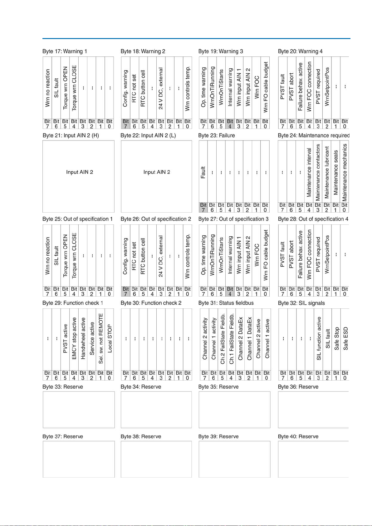
Byte 17:Warnings 1
The warning signals are for information only and do not interrupt or disable an
operation (as opposed to faults).
Table 14: Byte 17:Warnings 1
Bit
(process representation)
4
Bit: Torque warn. CLOSE
5
Bit: Torque warn. OPEN
6
Bit: SIL fault
7
Bit: No reaction
The safety function indications via fieldbus are for information only and must not be used as part of a safety function.The I/O signals of
1)
the SIL module must be used for this purpose.
1)
CLOSE"
OPEN"
DescriptionValuePrm-Text-Def GSD fileDesignation
No signal (reserved)——0
No signal (reserved)——1
No signal (reserved)——2
No signal (reserved)——3
Warning: Limit value for Torque warning CLOSE ex-
1(125) = "Bit:Torque wrn
ceeded
No signal0
Warning: Limit v alue for Torque warning OPEN exceeded1(124) = "Bit: Torque wrn
No signal0
Warning: A SIL fault of the SIL sub-assembly has oc-
1(206) = "SIL fault"
curred.
No signal0
Warning: No actuator reaction to operation commands
1(71) = "Bit: No reaction"
within the set reaction time.
No signal0
Table 15: Byte 18:Warnings 2
Bit
(process representation)
0
Bit: Wrn controls temp
3
Bit: 24 V DC, external
28
Byte 18:Warnings 2
sTemp"
al"
DescriptionValuePrm-Text-Def GSD fileDesignation
Warning:Temperature within controls housing too high1(88) = "Bit:WrnControlNo signal0
No signal (reserved)——1
No signal (reserved)——2
The external 24 V DC voltage supply of the controls has
1(68) = "Bit: 24 V DC, e xtern-
exceeded the power supply limits.
No signal0
Loading...