


SGExC 05.1
Table of contents
 Loading...
Part-turn actuators
SGExC 05.1 – SGExC 12.1
Control unit: electronic (MWG)
with actuator controls
AUMATIC ACExC 01.1 Non-Intrusive
Control
→ Parallel
Profibus DP
Modbus
DeviceNet
Foundation Fieldbus
Assembly, operation, commissioningOperation instructions

SGExC 05.1 – SGExC 12.1 Control unit: electronic (MWG)
Table of contents ACExC 01.1 Non-Intrusive
Read operation instructions first.
●
Observe safety instructions.
●
These operation instructions are part of the product.
●
Preserve operation instructions during product life.
●
Pass on instructions to any subsequent user or owner of the product.
Purpose of the document:
This document contains information for installation, commissioning, operation and maintenance staff . It is intended
to support device installation and commissioning.
Reference documents:
●
Manual (Operation and setting) AUMATIC AC 01.1/ACExC 01.1 Parallel
Reference documents can be downloaded from the Internet (www.auma.com) or ordered directly from AUMA
(refer to <Addresses>).
Table of contents Page
51. Safety instructions.................................................................................................................
51.1. Basic information on safety
51.2. Range of application
61.3. Warnings and notes
71.4. References and symbols
82. Identification...........................................................................................................................
82.1. Name plate
92.2. Short description
113. Transport, storage and packaging........................................................................................
113.1. Transport
113.2. Storage
113.3. Packaging
124. Assembly................................................................................................................................
124.1. Mounting position
124.2. Ball handle: fit to handwheel
124.3. Part-turn actuator to valve: mount
134.3.1 Coupling
144.4. Mounting positions of local controls
154.4.1 Mounting positions: modify
165. Electrical connection.............................................................................................................
165.1. Basic information
175.2. Connecting via plug/socket connector with screw-type terminals (KP, KPH)
175.2.1 Terminal compartment: open
185.2.2 Cable connection
195.2.3 Terminal compartment: close
205.3. Connecting via plug/socket connector with terminal blocks (KES)
205.3.1 Terminal compartment: open
215.3.2 Cable connection
225.3.3 Terminal compartment: close
225.4. Accessories for electrical connection
225.4.1 Controls mounted to wall bracket
235.4.2 Parking frame
2

SGExC 05.1 – SGExC 12.1 Control unit: electronic (MWG)
ACExC 01.1 Non-Intrusive Table of contents
235.4.3 Protection cover
246. Operation................................................................................................................................
246.1. Manual operation
246.1.1 Manual operation: engage
246.1.2 Manual operation: disengage
246.2. Motor operation
246.2.1 Local operation
256.2.2 Operation from REMOTE
266.3. Menu navigation via push buttons (for settings and indications)
266.3.1 Short overview: Functions of the push buttons
266.3.2 Structural design and navigation
276.4. Password entry
286.5. Language change in the display
307. Indications..............................................................................................................................
307.1. Status indications in the display
307.1.1 Status indication S0/S6 - operation
317.1.2 Status indication S4 - torque
317.1.3 Torque indication: edit
317.2. Indication lights/LEDs
327.3. Mechanical position indicator/running indication
338. Signals.....................................................................................................................................
338.1. Feedback signals via output contacts (binary)
338.2. Feedback signals (analogue)
349. Commissioning (basic settings)...........................................................................................
349.1. Heat-up time for low temperature version
349.2. End stops in part-turn actuator
359.2.1 End stop CLOSED: set
369.2.2 End stop OPEN: set
369.3. Swing angle
379.3.1 Swing angle: modify
389.4. Type of seating: check/edit for end positions
419.5. Torque switching: check/set
459.6. Limit switching: set
489.7. Test run
489.7.1 Direction of rotation: check
489.7.2 Limit switching: check
499.8. Switch compartment: open
499.9. Mechanical position indicator: set
509.10. Switch compartment: close
509.11. Operating time: set
5210. Corrective action....................................................................................................................
5210.1. Faults during commissioning
5210.2. Fault indications and warning indications
5210.2.1 Status indication S0 - faults and warnings
5210.2.2 Status indication S1 - faults
5310.2.3 Status indication S2 - warnings
5410.2.4 Status indication S3 - causes for not ready remote
5410.3. Fuses
3

SGExC 05.1 – SGExC 12.1 Control unit: electronic (MWG)
Table of contents ACExC 01.1 Non-Intrusive
5410.3.1 Fuses within the actuator controls
5510.3.2 Motor protection (thermal monitoring)
5711. Servicing and maintenance...................................................................................................
5711.1. Preventive measures for servicing and safe operation
5711.2. Disconnection from the mains
5811.3. Maintenance
5911.4. Disposal and recycling
6012. Technical data.........................................................................................................................
6012.1. Features and functions of actuator
6112.2. Features and functions of actuator controls
6312.3. Service conditions
6412.4. Accessories
6412.5. Further information
6513. Spare parts.............................................................................................................................
6513.1. Part-turn actuators SGExC 05.1 – SGExC 12.1 via plug/socket connector with screw-type
terminals (KP, KPH)
6713.2. Actuator controls AUMATIC ACExC 01.1 via plug/socket connector with scre w-type terminals
(KP, KPH)
6913.3. Actuator controls AUMATIC ACExC 01.1 with plug/socket connector and terminal blocks
(KES)
7114. Certificates..............................................................................................................................
7114.1. Declaration of Incorporation and EC Declaration of Conformity
7214.2. ATEX certificate
7515. Index........................................................................................................................................
77Addresses...............................................................................................................................
4

SGExC 05.1 – SGExC 12.1 Control unit: electronic (MWG) ACExC 01.1 Non-Intrusive Safety instructions
1. Safety instructions
1.1 Basic information on safety Standards/directives
Safety instructions/war-
nings
Qualification of staff
AUMA products are designed and manufactured in compliance with recognised
standards and directives.This is certified in a Declaration of Incorporation and an
EC Declaration of Conformity.
The end user or the contractor must ensure that all legal requirements, directives,
guidelines, national regulations and recommendations with respect to assembly,
electrical connection, commissioning and operation are met at the place of installation.
They include among others standards and directives such as IEC/EN 60079 “Electrical
apparatus for explosive atmospheres" –
●
Part 14: Electrical installations in hazardous areas (other than mines).
●
Part 17: Inspection and maintenance of electrical installations in hazardous
areas (other than mines).
All personnel working with this device must be familiar with the safety and warning
instructions in this manual and observe the instructions given. Safety instructions
and warning signs on the device must be observed to av oid personal injury or property
damage.
Assembly, electrical connection, commissioning, operation, and maintenance must
be carried out exclusively by suitab ly qualified personnel ha ving been authorised by
the end user or contractor of the plant only.
Prior to working on this product, the staff must have thoroughly read and understood
these instructions and, furthermore, know and observe officially recognised rules
regarding occupational health and safety.
Work performed in potentially explosiv e atmospheres is subject to special regulations
which have to be observed.The end user or contractor of the plant are responsible
for respect and control of these regulations, standards, and laws.
Commissioning
Operation
Protective measures
Maintenance
Prior to commissioning, it is important to check that all settings meet the requirements
of the application. Incorrect settings might present a danger to the application, e.g.
cause damage to the valve or the installation.The manufacturer will not be held
liable for any consequential damage. Such risk lies entirely with the user.
Prerequisites for safe and smooth operation:
●
Correct transport, proper storage, mounting and installation, as well as careful
commissioning.
●
Only operate the device if it is in perf ect condition while observing these instructions.
●
Immediately report any faults and damage and allow for corrective measures.
●
Observe recognised rules for occupational health and safety.
●
Observe the national regulations.
●
During operation, the housing warms up and surface temperatures > 60 °C may
occur.To prevent possible burns, we recommend checking the surface temperature using an appropriate thermometer and wearing protective gloves, if required, prior to working on the device.
The end user or the contractor are responsible for implementing required protective
measures on site, such as enclosures, barriers, or personal protective equipment
for the staff.
T o ensure saf e device operation, the maintenance instructions included in this manual
must be observed.
Any device modification requires prior consent of the manufacturer.
1.2 Range of application
AUMA part-turn actuators are designed for the operation of industrial valves, e.g.
butterfly valves and ball valves.
5

SGExC 05.1 – SGExC 12.1 Control unit: electronic (MWG)
Safety instructions ACExC 01.1 Non-Intrusive
The devices described below are approved for use in the potentially explosive
atmospheres of zones 1, 2, 21, and 22.
If temperatures >40 °C are to be expected at the valve mounting flange or the valve
stem (e.g. due to hot media), please consult AUMA.Temperatures > 40 °C are not
considered with regards to the non-electrical explosion protection.
Other applications require explicit (written) confirmation by the manufacturer.
The following applications are not permitted, e.g.:
●
Industrial trucks according to EN ISO 3691
●
Lifting appliances according to EN 14502
●
Passenger lifts according to DIN 15306 and 15309
●
Service lifts according to EN 81-1/A1
●
Escalators
●
Continuous duty
●
Buried service
●
Permanent submersion (observe enclosure protection)
●
Potentially explosive areas of zones 0 and 20
●
Potentially explosive areas of group I (mining)
●
Radiation exposed areas in nuclear power plants
No liability can be assumed for inappropriate or unintended use.
Observance of these operation instructions is considered as part of the device's
designated use.
Information
These operation instructions are only valid for the "clockwise closing" standard
version, i.e. driven shaft turns clockwise to close the valve.
1.3 Warnings and notes
The following warnings draw special attention to saf ety-rele v ant procedures in these
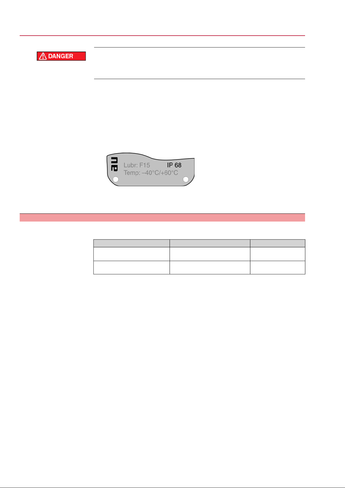
operation instructions, each marked by the appropriate signal word (DANGER,
WARNING, CAUTION, NOTICE).
Indicates an imminently hazardous situation with a high level of risk. Failure
to observe this warning could result in death or serious injury.
Indicates a potentially hazardous situation with a medium level of risk. F ailure
to observe this warning could result in death or serious injury.
Indicates a potentially hazardous situation with a low level of risk. Failure to
observe this warning may result in minor or moderate injury . Ma y also be used
with property damage.
Potentially hazardous situation. Failure to observe this warning may result in
property damage. Is not used for personal injury.
Arrangement and typographic structure of the warnings
Type of hazard and respective source!
Potential consequence(s) in case of non-observance (option)
→
Measures to avoid the danger
→
Further measure(s)
Safety alert symbol warns of a potential personal injury hazard.
6
SGExC 05.1 – SGExC 12.1 Control unit: electronic (MWG)
ACExC 01.1 Non-Intrusive Safety instructions
The signal word (here: DANGER) indicates the level of hazard.
1.4 References and symbols
The following references and symbols are used in these instructions:
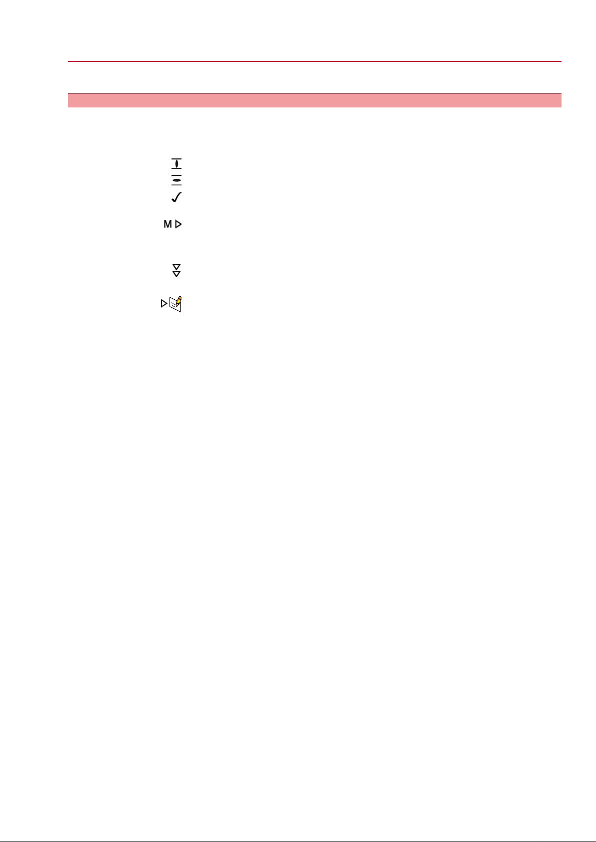
Information The term Information preceding the text indicates important notes and information.
Symbol for CLOSED (valve closed)
Symbol for OPEN (valve open)
Important information before the next step.This symbol indicates what is required
for the next step or what has to be prepared or observed.
Via the menu to parameter
Describes the path within the menu to the parameter. By using the push buttons of
the local controls you may quickly find the desired parameter in the display.
Step by step
Provides a detailed description of each step for setting/viewing the parameter.
Description of the parameter settings/indications
Describes the setting/viewing possibilities of a parameter.
< > Reference to other sections
T erms in brack ets shown abov e refer to other sections of the document which provide
further information on this topic.These terms are either listed in the index, a heading
or in the table of contents and may quickly be found.
7

SGExC 05.1 – SGExC 12.1 Control unit: electronic (MWG)
Identification ACExC 01.1 Non-Intrusive
2. Identification
2.1 Name plate
Each device component (actuator, controls, motor) is equipped with a name plate.
Figure 1: Arrangement of name plates
[1] Actuator name plate
[2] Controls name plate
[3] Motor name plate
[4] Additional plate, e.g. KKS plate (Power Plant Classification System)
[5] Explosion protection approval plate
Data for identification Figure 2: Actuator name plate
[1] Type and size of actuator
[2] Commission number
Figure 3: Controls name plate
[1] Type and size of the controls
[2] Commission number
[3] Wiring diagram
[4] Control
8

SGExC 05.1 – SGExC 12.1 Control unit: electronic (MWG)
ACExC 01.1 Non-Intrusive Identification
Figure 4: Explosion protection approval plate
[1] Ex symbol, CE mark, number of notified body
[2] EC type examination certificate
[3] Explosion protection classification - electrical explosion protection
[4] Explosion protection classification - dust protection
[5] Explosion protection classification - non-electrical explosion protection
Type and size
Commission number
Wiring diagram
Control
2.2 Short description
Part-turn actuator
Actuator controls
Local controls/COM-AC
These instructions apply to the following devices:
Part-turn actuators for open-close duty: SGExC 05.1, 07.1, 10.1, 12.1
ACExC 01.1 = actuator controls AUMATIC
An order-specific commission number is assigned to each device.This commission
number can be used to directly download the wiring diagram, inspection records and
further information regarding the device from the Internet: http://www.auma.com.
The 7th position in the ACP wiring diagram indicates the type of feedback signals
from the actuator:
M = MWG, <Non-Intrusive version>.
P = Potentiometer
R = RWG (electronic position transmitter)
24 V DC = Control via parallel interface at 24 V DC control voltage.
115 V AC = Control via parallel interface at 115 V AC control voltage.
0/4 – 20 mA = Control via parallel interface via analogue input 0/4 – 20 mA.
Definition in compliance with EN ISO 5211:
A part-turn actuator is an actuator which transmits a torque to the valve for less than
one full revolution. It need not be capable of withstanding thrust.
AUMA part-turn actuators are driven by an electric motor. A handwheel is provided
for manual operation. Switching off in end positions may be either by limit or torque
seating. Controls are required to operate or process the actuator signals.
The AUMATIC actuator controls are used to operate AUMA actuators and are supplied
ready for use.The controls may be mounted directly to the actuator or separately
on a wall bracket.
The functions of the AUMATIC controls include standard valve control in OPEN CLOSE duty, positioning, process control, logging of operating data right through to
diagnostic functions.
Operation, setting, and display can be performed on site directly at the controls
On site it is possible to
●
Operate the actuator via the local controls (push buttons and display) and perform settings (contents of these instructions).
●
Read in or out data or modify and save settings via the COM-A C softw are (option), using a computer (laptop or PC). Depending on the version, the connection between computer and AUMATIC can be made with cable (infra-red interface) or without cable (Bluetooth interf ace) (not included in these instructions).
9

SGExC 05.1 – SGExC 12.1 Control unit: electronic (MWG)
Identification ACExC 01.1 Non-Intrusive
●
Intrusive - Non-Intrusive
Intrusive version (control unit: electromechanical):
Limit and torque setting is performed via switches in the actuator.
●
Non-Intrusive version (control unit: electronic):
Limit and torque setting is performed via the controls, actuator and controls
housings do not have to be opened. For this purpose, the actuator is equipped
with an MWG (magnetic limit and torque transmitter), also supplying analogue
torque feedback signals/torque indication and analogue position feedback signals/position indication.
10

SGExC 05.1 – SGExC 12.1 Control unit: electronic (MWG) ACExC 01.1 Non-Intrusive Transport, storage and packaging
3. Transport, storage and packaging
3.1 Transport
For transport to place of installation, use sturdy packaging.
Hovering load!
Risk of death or serious injury.
→
Do NOT stand below hovering load.
→
Attach ropes or hooks for the purpose of lifting by hoist only to housing and NOT
to handwheel.
→
Actuators mounted on valves: Attach ropes or hooks for the purpose of lifting
by hoist to valve and NOT to actuator.
→
Actuators mounted to gearboxes: Attach ropes or hooks f or the purpose of lifting
by hoist only to the gearbox using eyebolts and NOT to the actuator.
→
Actuators mounted to controls: Attach ropes or hooks for the purpose of lifting
by hoist only to the actuator and NOT to the controls.
3.2 Storage
Long-term storage
3.3 Packaging
Danger of corrosion due to inappropriate storage!
→
Store in a well-ventilated, dry room.
→
Protect against floor dampness by storage on a shelf or on a wooden pallet.
→
Cover to protect against dust and dirt.
→
Apply suitable corrosion protection agent to uncoated surfaces.
Damage on display caused by temperatures below permissible level!
→
The AUMATIC actuator controls must NOT be stored below –30 °C.
If the device must be stored for a long period (more than 6 months) the following
points must be observed in addition:
1. Prior to storage:
Protect uncoated surfaces, in particular the output drive parts and mounting
surface, with long-term corrosion protection agent.
2. At an interval of approx. 6 months:
Check for corrosion. If first signs of corrosion show , apply ne w corrosion protection.
Our products are protected by special packaging for transport when leaving the
factory .The packaging consists of environmentally friendly materials which can easily
be separated and recycled.We use the following packaging materials: wood,
cardboard, paper, and PE foil. For the disposal of the packaging material, we
recommend recycling and collection centres.
11
SGExC 05.1 – SGExC 12.1 Control unit: electronic (MWG)
Assembly ACExC 01.1 Non-Intrusive
4. Assembly
4.1 Mounting position
AUMA actuators and actuator controls can be operated without restriction in any
mounting position.
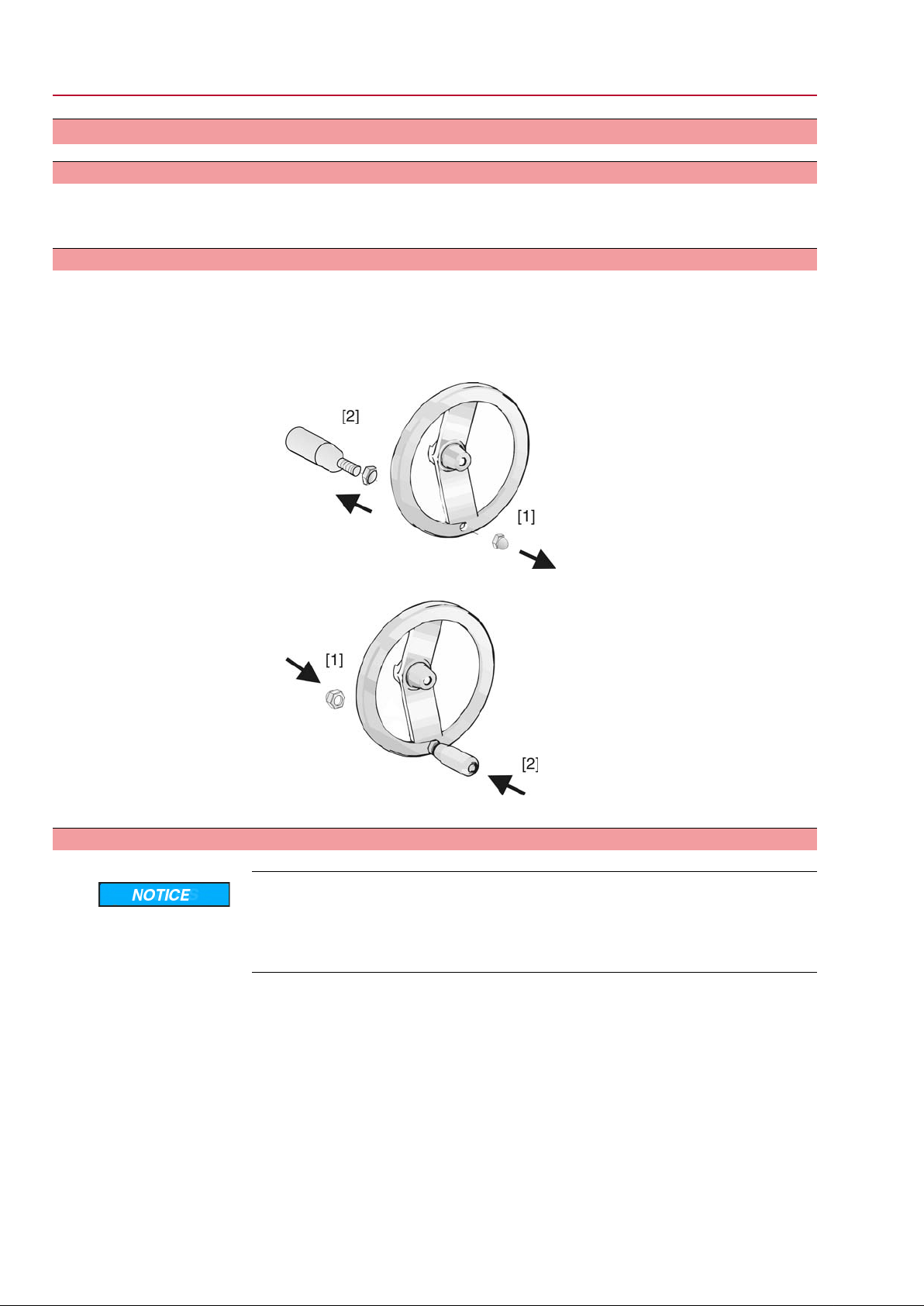
4.2 Ball handle: fit to handwheel
To avoid damage during transport, the ball handle is fitted at the rear of the
handwheel.
Prior to commissioning, mount the ball handle into correct position:
1. Remove cap nut [1] and pull out ball handle [2].
2. Insert ball handle [2] in correct position and fasten with cap nut [1].
3. After ball handle fitting, remove label from handwheel.
4.3 Part-turn actuator to valve: mount
Danger of corrosion due to damage to paint finish and condensation!
→
Touch up damage to paint finish after work on the device.
→
After mounting, connect the device immediately to electrical mains to ensure
that heater prevents condensation.
12
SGExC 05.1 – SGExC 12.1 Control unit: electronic (MWG)
ACExC 01.1 Non-Intrusive Assembly
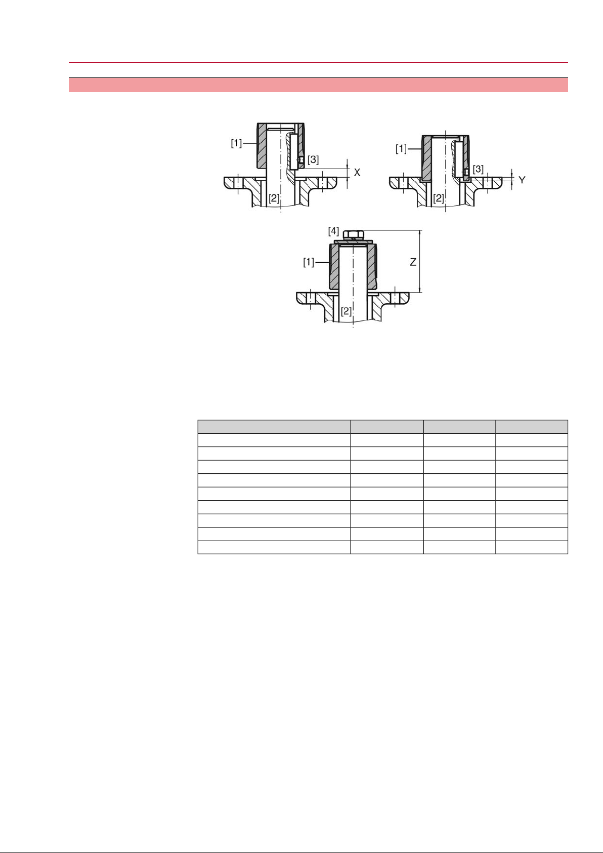
4.3.1 Coupling
Figure 7: Coupling fitting dimensions
[1] Coupling
[2] Valve shaft
[3] Grub screw
[4] Screw
Table 1: Coupling fitting dimensions
Z max [mm]Y max [mm]X max [mm]Type, size - mounting flange
60–9SGExC 05.1-F05
60–9SGExC 05.1-F07
60–9SGExC 07.1-F07
75–24SGExC 07.1-F10
77915SGExC 10.1-F10
97–32SGExC 10.1-F12
100–25SGExC 12.1-F12
120–45SGExC 12.1-F14
132–57SGExC 12.1-F16
1. Use handwheel to drive actuator to mechanical end stop.
Information: Assemble valve and actuator in the same end position.
- With butterfly valves: recommended mounting position is end position
CLOSED.
- With ball valves: recommended mounting position is end position OPEN.
2. Thoroughly degrease mounting faces of the mounting flange.
3. Apply a small quantity of grease to the valve shaft [2].
4. Place coupling [1] onto valve shaft [2] and secure against axial slipping by using
a grub screw, a circlip or a screw.Thereby, ensure that dimensions X, Y or Z
are observed (refer to figure and table <Coupling fitting dimensions>).
5. Apply non-acidic grease at splines of coupling.
6. Fit actuator.
Information: Ensure that the spigot (if provided) fits uniformly in the recess
and that the flanges are in complete contact.
7. If flange bores do not match thread:
7.1 Slightly rotate handwheel until bores line up.
7.2 If required, shift actuator position by one tooth on the coupling.
13
SGExC 05.1 – SGExC 12.1 Control unit: electronic (MWG)
Assembly ACExC 01.1 Non-Intrusive
8. Fasten actuator with screws [4].
Information:We recommend glueing the screws using sealing material to avoid
contact corrosion.
→
Fasten screws [4] crosswise with a torque according to table:
Table 2: Tightening torques for screws
Thread
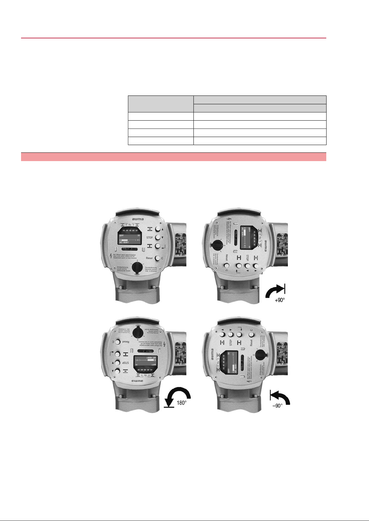
4.4 Mounting positions of local controls
The mounting position of the local controls is selected according to the order. If , after
mounting the actuator to the valve or the gearbox on site, the local controls are in
an unfav ourable position, the mounting position can be changed at a later date . F our
mounting positions are possible.
Figure 8: Mounting positions A-2 and B-2
Tightening torque TA [Nm]Screws
Strength class 8.8
11M6
25M8
51M10
87M12
Figure 9: Mounting positions C-2 and D-2
14
SGExC 05.1 – SGExC 12.1 Control unit: electronic (MWG)
ACExC 01.1 Non-Intrusive Assembly
4.4.1 Mounting positions: modify
Flameproof enclosure, danger of explosion!
Risk of death or serious injury.
→
Before opening, ensure that there is no explosive gas and no voltage.
→
Handle cover and housing parts with care.
→
Joint surfaces must not be damaged or soiled in any way.
→
Do not jam cover during fitting.
1. Loosen screws and remove the local controls.
2. Check whether O-ring is in good condition, correctly insert O-ring.
3. Turn local controls into new position and re-place.
Cable damage due to twisting or pinching!
Risk of functional failures.
→
Turn local controls by a maximum of 180°.
→
Carefully assemble local controls to avoid pinching the cables.
4. Fasten screws evenly crosswise.
15

SGExC 05.1 – SGExC 12.1 Control unit: electronic (MWG)
Electrical connection ACExC 01.1 Non-Intrusive
5. Electrical connection
5.1 Basic information
Danger due to incorrect electrical connection
Failure to observe this warning can result in death, serious injury , or property damage.
→
The electrical connection must be carried out exclusively by suitably qualified
personnel.
→
Prior to connection, observe basic information contained in this chapter.
→
After connection but prior to applying the voltage, observe the <Commissioning>
and <Test run> chapters.
Wiring diagram/terminal
plan
Protection on site
The pertaining wiring diagram/terminal plan (in German and English language) is
attached to the device in a weather-proof bag, together with these operation
instructions. It can also be obtained from A UMA (state commission no ., refer to name
plate) or downloaded directly from the Internet (www.auma.com).
For short-circuit protection and for disconnecting the actuator from the mains, fuses
and disconnect switches have to be provided by the customer.
The current values for respective sizing is derived from the current consumption of
the motor (refer to electrical data sheet) plus the current consumption of the controls.
Table 3: Current consumption controls
Max. current consumptionMains voltage
650 mA100 to 120 V AC (±10 %)
325 mA208 to 240 V AC (±10 %)
190 mA380 to 500 V AC (±10 %)
500 mA, filter capacitor 2,200 µF24 V DC (+10 %/-15 %) and AC motor
750 mA, filter capacitor 2,200 µF24 V DC (+10 %/–10 %) and DC motor
Table 4: Maximum permissible protection
max. protectionRated powerSwitchgear
16 A (gL/gG)up to 1.5 kWReversing contactor A1
If controls are mounted separately from actuator (controls on wall brack et): Consider
length and cross section of connecting cable when defining the protection required.
Power supply for the
controls (electronics)
Potential of customer
connections
Safety standards
Cable installation in ac-
cordance with EMC
16
If the controls (electronics) are supplied externally with 24 V DC and DC motors (24
V DC, 48 V DC, 60 V DC, 110 V DC, 220 V DC) are used simultaneously, the 24 V
DC voltage supply for the controls should be ensured via the XK25/26 terminals,
separately from the power supply (U1, V1). In case of common supply using a single
cable (links from U1, V1 with XK25/26, for 24 V DC only !!!), short-term excess or
falling below the permissible voltage limits can be the consequence during s witching
(24 V DC +10 %/–10 %). Any possibly incoming operation commands are not
executed outside the admissible limit values.The controls briefly signal a fault
condition.
All input signals (control) must be supplied with the same potential.
All output signals (status signals) must be supplied with the same potential.
All externally connected devices shall comply with the relevant safety standards.
Signal and bus cables are susceptible to interference.
Motor cables are interference sources.
●
Lay cables being susceptible to interference or sources of interference at the
highest possible distance from each other.

SGExC 05.1 – SGExC 12.1 Control unit: electronic (MWG)
ACExC 01.1 Non-Intrusive Electrical connection
●
The interference immunity of signal and bus cables increases if the cables are
laid close to the earth potential.
●
If possible, avoid laying long cables and make sure that they are installed in
areas being subject to low interference.
●
Avoid long par allel paths with cab les being either susceptible to interf erence or
interference sources.
●
For the connection of remote position transmitters, screened cables must be
used.
Type of current, mains
voltage and mains fre-
quency
Type of current, mains voltage and mains frequency must match the data on the
motor name plate.
Figure 10: Motor name plate (example)
[1] Type of current
[2] Mains voltage
[3] Mains frequency (for 3-ph and 1-ph AC motors)
●
Connecting cables
For device insulation, appropriate (v oltage-proof) cables must be used. Specify
cables for the highest occurring rated voltage.
●
Use connecting cables with a minimum temperature range of +80 °C.
●
For connecting cables exposed to UV radiation (outdoor installation), use UV
resistant cables.
5.2 Connecting via plug/socket connector with screw-type terminals (KP, KPH)
5.2.1 Terminal compartment: open
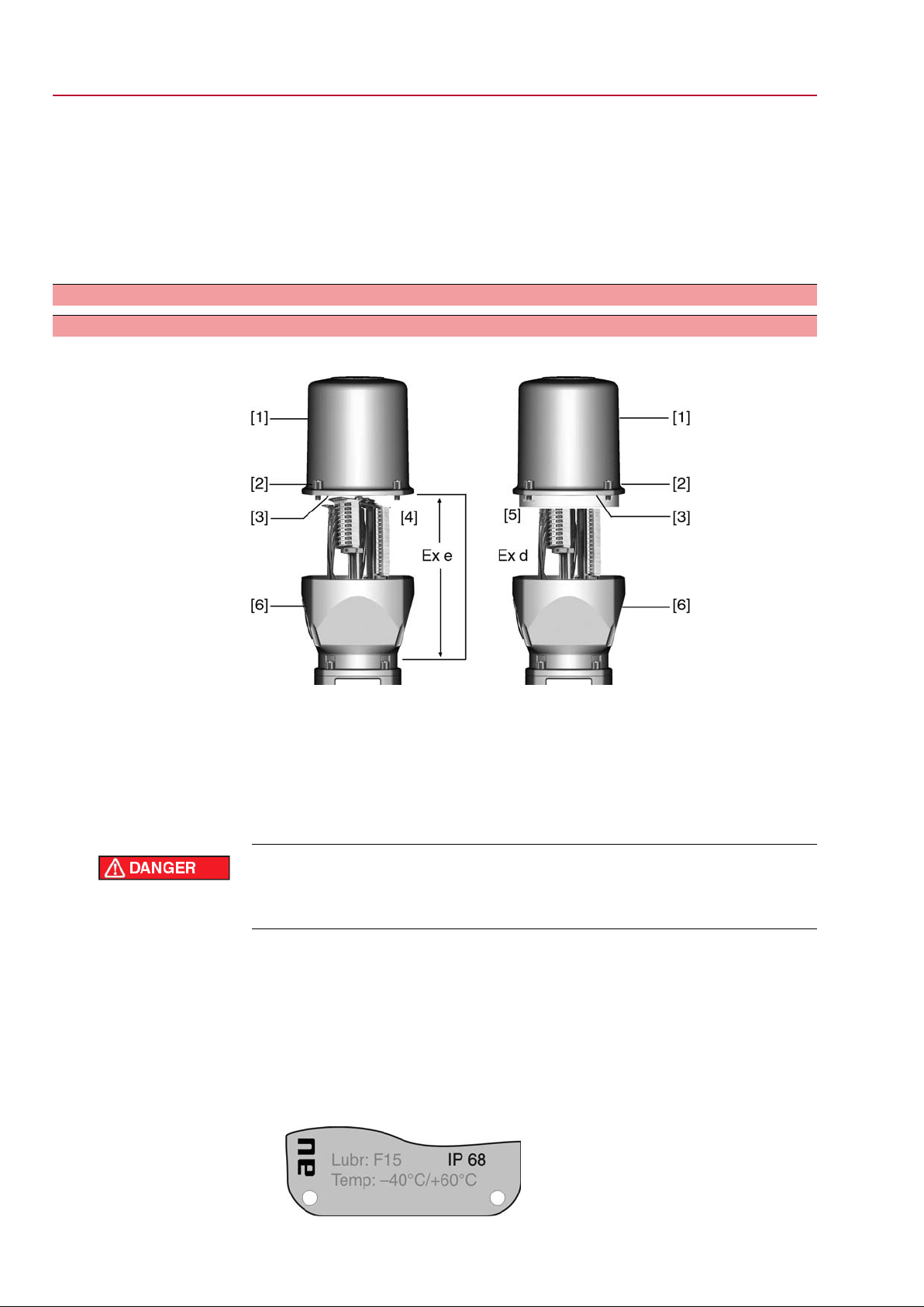
Figure 11: Plug/socket connector KPH, KP
[1] Cover
[2] Screws for cover
[3] O-ring
[4] Terminal compartment
[5] Terminal board
17
SGExC 05.1 – SGExC 12.1 Control unit: electronic (MWG)
Electrical connection ACExC 01.1 Non-Intrusive
Hazardous voltage!
Risk of electric shock.
→
Disconnect device from the mains before opening.
1. Loosen screws [2] and remove cover [1].
Terminal compartment [4] is designed for explosion protection Ex e (increased
➥
safety).The flameproof compartment (type of protection Ex d) remains hereby
closed.
2. Insert cable glands with Ex e approv al and of size suitable f or connection cables.
The enclosure protection IP… stated on the name plate is only ensured if suita-
➥
ble cable glands are used. Example: Name plate shows enclosure protection
IP 68.
5.2.2 Cable connection
3. Seal cable entries which are not used with approved plugs suitable for the required protection type.
4. Insert the wires into the cable glands.
Table 5: Terminal cross sections and tightening torques
Tightening torquesTerminal cross sectionsType
Power terminals (U1, V1, W1)
PE connection
Control contacts (1 to 50)
with small clamp washers1)
(flexible or solid)
(flexible or solid)
2 Nm(1.5)1) 2.5 – 6 mm²
1 Nm0.75 – 1.5 mm²
1. Remove cable sheathing in a length of 120 – 140 mm.
2. Strip wires.
→
Controls max. 8 mm, motor 12 mm
3. For flexible cables: Use end sleeves according to DIN 46228.
4. Connect cables according to order-related wiring diagram.
Information: Two wires for each connection permitted.
→
When using motor cables with a cross section of 1.5 mm²: Use small clamp
washers for connection to terminals U1, V1, W1 and PE (the small clamp
washers are provided in the electrical connection cover).
18
SGExC 05.1 – SGExC 12.1 Control unit: electronic (MWG)
ACExC 01.1 Non-Intrusive Electrical connection
In case of a fault: Hazardous voltage while protective earth conductor is NOT
connected!
Risk of electric shock.
→
Connect all protective earth conductors.
→
Connect PE connection to external protective earth conductor of connecting
cables.
→
Start running the device only after having connected the protective earth conductor.
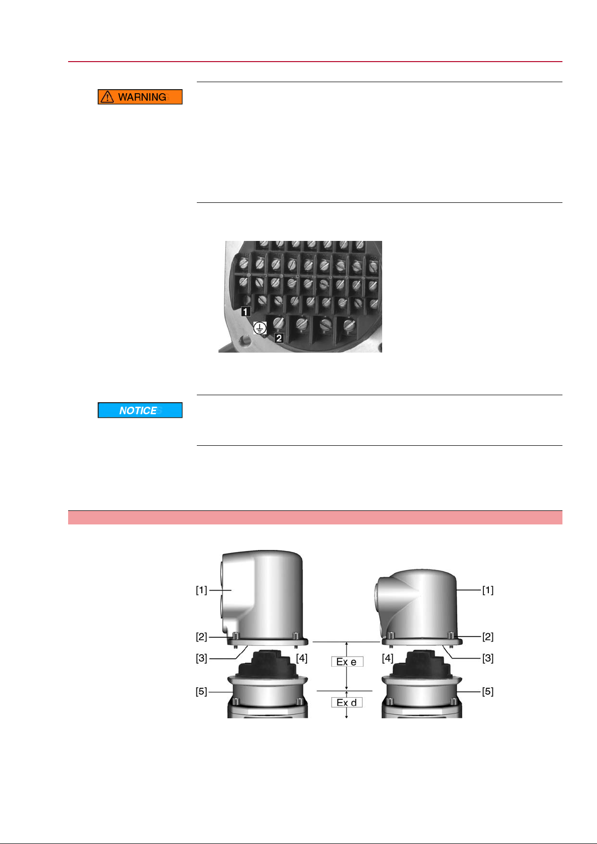
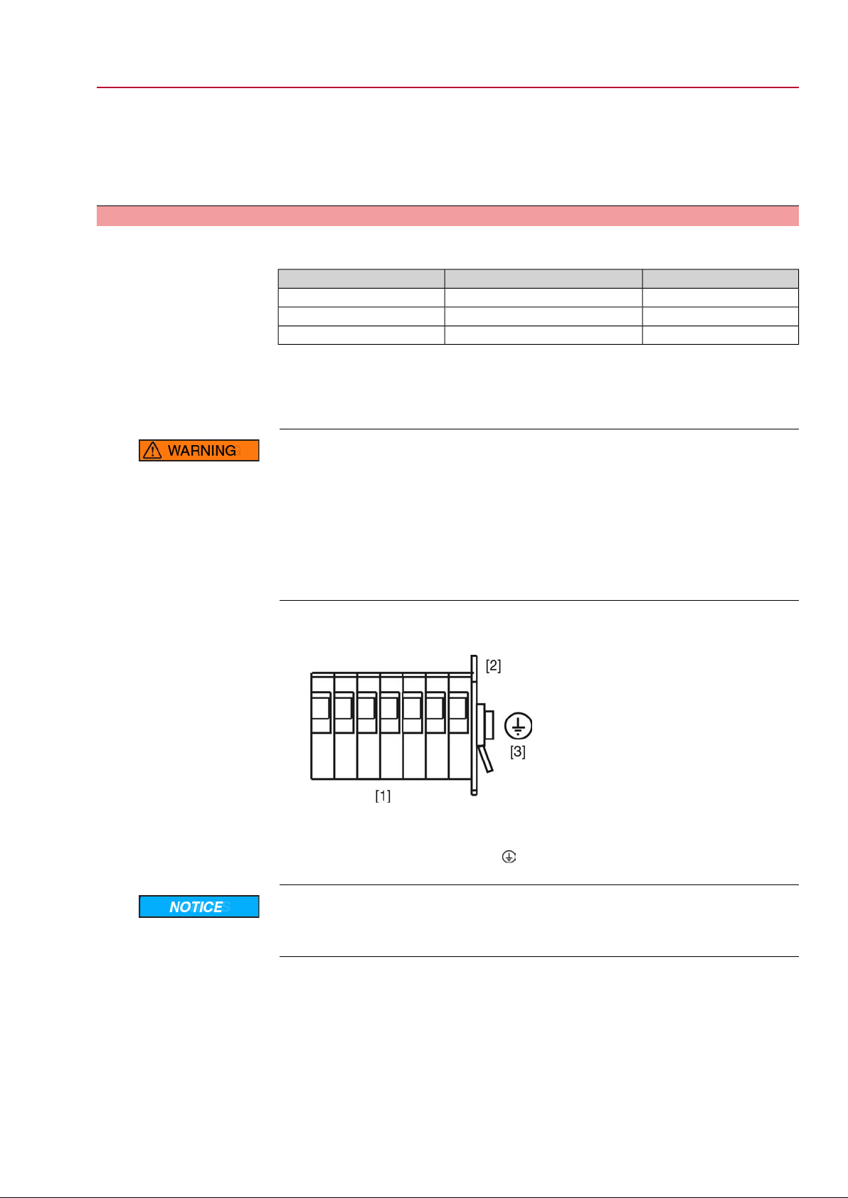
5. Tighten protective earth firmly to PE connection
Figure 13: PE connection
[1] PE connection, control cable
[2] PE connection, motor cable
Danger of corrosion: Damage due to condensation!
→
After mounting, commission the device immediately to ensure that heater minimises condensation.
Information Some actuators are equipped with an additional motor heater.The motor heater
minimises condensation within the motor and improves the start-up behaviour for
extremely low temperatures.
5.2.3 Terminal compartment: close
Figure 14: Plug/socket connector KPH, KP
[1] Cover
[2] Screws for cover
[3] O-ring
[4] Terminal compartment
[5] Terminal board
19
SGExC 05.1 – SGExC 12.1 Control unit: electronic (MWG)
Electrical connection ACExC 01.1 Non-Intrusive
1. Clean sealing faces of cover [1] and housing.
2. Check whether O-ring [3] is in good condition, replace if damaged.
3. Apply a thin film of non-acidic grease (e.g. petroleum jelly) to the O-ring and
insert it correctly.
4. Fit cover [1] and fasten screws [2] evenly crosswise.
5. Fasten cable glands with the specified torque to ensure the required enclosure
protection.
5.3 Connecting via plug/socket connector with terminal blocks (KES)
5.3.1 Terminal compartment: open
Figure 15: Plug/socket connector: left KES, right KES flameproof
[1] Cover
[2] Screws for cover
[3] O-ring
[4] Terminal compartment: Type of protection Ex e
[5] Terminal compartment: Type of protection Ex d
[6] Frame
Hazardous voltage!
Risk of electric shock.
→
Disconnect device from the mains before opening.
1. Loosen screws [2] and remove cover [1].
Terminal compartments [4] and [5] designed either in type of protection Ex e
➥
(increased safety) or in type of protection Ex d (flameproof enclosure). Hereby,
the flameproof interior compartment of the actuator (Ex d) remains closed.
2. Insert cable glands with Ex e approv al and of size suitable f or connection cables.
The enclosure protection IP… stated on the name plate is only ensured if suita-
➥
ble cable glands are used. Example: Name plate shows enclosure protection
IP 68.
20
SGExC 05.1 – SGExC 12.1 Control unit: electronic (MWG)
ACExC 01.1 Non-Intrusive Electrical connection
3. Seal cable entries which are not used with approved plugs suitable for the required protection type.
4. Remove cable sheathing and insert the wires into the cable glands.
5. Fasten cable glands with the specified torque to ensure the required enclosure
protection.
5.3.2 Cable connection
Table 6: Terminal cross sections and tightening torques
Tightening torquesTerminal cross sectionsType
1.5 – 1.8 Nmmax. 10 mm² (flexible or solid)Power terminals (U, V, W)
3.0 – 4.0 Nmmax. 10 mm² (flexible or solid)PE connection
0.6 – 0.8 Nmmax.2.5 mm² (flexible or solid)Control contacts (1 to 50)
1. Strip wires.
2. For flexible cables: Use end sleeves according to DIN 46228.
3. Connect cables according to order-related wiring diagram.
In case of a fault: Hazardous voltage while protective earth conductor is NOT
connected!
Risk of electric shock.
→
Connect all protective earth conductors.
→
Connect PE connection to external protective earth conductor of connecting
cables.
→
Start running the device only after having connected the protective earth conductor.
4. Tighten protective earth firmly to PE connection
Figure 17: PE connection
[1] Terminal blocks
[2] Terminal housing
[3]
PE connection, symbol:
Danger of corrosion: Damage due to condensation!
→
After mounting, commission the device immediately to ensure that heater minimises condensation.
Information Some actuators are equipped with an additional motor heater.The motor heater
minimises condensation within the motor and improves the start-up behaviour for
extremely low temperatures.
21

SGExC 05.1 – SGExC 12.1 Control unit: electronic (MWG)
Electrical connection ACExC 01.1 Non-Intrusive
5.3.3 Terminal compartment: close
Figure 18: Plug/socket connector: left KES, right KES flameproof
[1] Cover
[2] Screws for cover
[3] O-ring
[4] Terminal compartment: Type of protection Ex e
[5] Terminal compartment: Type of protection Ex d
[6] Frame
1. Clean sealing faces of cover [1] and housing.
2. Plug/socket connector designed as KES flameproof: Preserve joint surfaces
with an acid-free corrosion protection agent.
3. Check whether O-ring [3] is in good condition, replace if damaged.
4. Apply a thin film of non-acidic grease (e.g. petroleum jelly) to the O-ring and
insert it correctly.
Flameproof enclosure, danger of explosion!
Risk of death or serious injury.
→
Handle cover and housing parts with care.
→
Joint surfaces must not be damaged or soiled in any way.
→
Do not jam cover during fitting.
5. Fit cover [1] and fasten screws [2] evenly crosswise.
5.4 Accessories for electrical connection — Option —
5.4.1 Controls mounted to wall bracket
The wall bracket allows separate mounting of controls and actuator.
●
Application
Design
Observe prior to
connection
If the actuator cannot be accessed.
●
If the actuator is subject to high temperatures.
●
In case of heavy vibration of the valve.
●
Permissible length of connecting cables: max. 100 m.
●
Permissible length of connecting cables for later separation of actuator and
controls: max. 10 m.
●
We recommend: AUMA cable sets LSW21-KES or LSW22-KP.
22
SGExC 05.1 – SGExC 12.1 Control unit: electronic (MWG)
ACExC 01.1 Non-Intrusive Electrical connection
●
If the AUMA cable set is not used:
- Use suitable flexible and screened connecting cables.
- Use separate CAN bus cable of 120 Ohm character impedance for MWG
(e.g. UNITRONIC BUS-FD P CAN UL/CSA - 2 x 2 x 0.5 mm², manuf acturer:
Lapp).
- Data cable connection: XM2-XA2 = CAN L, XM3-XA3 = CAN H.
- MWG voltage supply if the A UMATIC has been ordered and delivered with
wall bracket: XM6-XA6 = GND, XM7-XA7 = + 24 V DC (refer to wiring
diagram).
- MWG voltage supply if A UMATIC has been subsequently separated from
the actuator: XM6-XA6 = GND, XM11-XA117 = + 5 V DC (refer to wiring
diagram).
●
When using connecting cables, e.g. of the heater, requiring direct wiring from
the actuator to the XK customer plug (XA-XM-XK, refer to wiring diagram),
these connecting cables must be subject to an insulation test in compliance
with EN 50178. Connecting cables for MWG do not belong to this group.They
may not be subject to an insulation test.
5.4.2 Parking frame Application
Parking frame for safe storage of a disconnected plug.
For protection against touching the bare contacts and against environmental
influences.
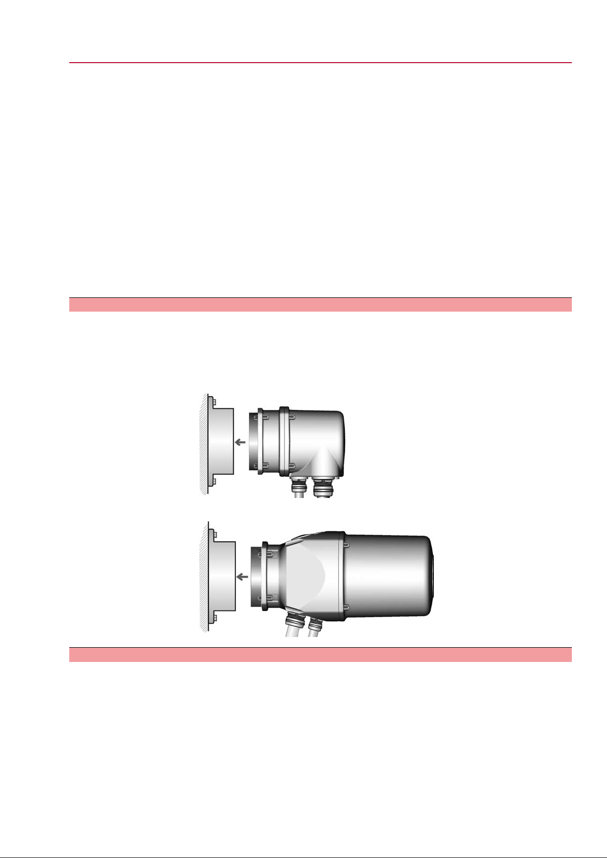
Figure 19: Parking frame and plug/socket connector with screw-type terminals
(KP/KPH)
Figure 20: Parking frame and plug/socket connector with terminal blocks (KES)
5.4.3 Protection cover
Protection cover for plug compartment when plug is removed.
The open terminal compartment can be closed using a protective cover (not
illustrated).
23

SGExC 05.1 – SGExC 12.1 Control unit: electronic (MWG)
Operation ACExC 01.1 Non-Intrusive
6. Operation
6.1 Manual operation
For purposes of setting and commissioning, in case of motor failure or power f ailure,
the actuator may be operated manually.
The handwheel does not rotate during motor operation. Change-over from motor
operation to manual operation is not required.
6.1.1 Manual operation: engage
→
Engage manual operation by pulling the handwheel.
Information T urning the handwheel during motor operation extends or reduces the oper ating time,
depending on the direction of rotation.
6.1.2 Manual operation: disengage
→
Release handwheel.
A spring pulls back the handwheel into the initial position.
➥
Information Handwheel must engage, assist by turning manually, if required.
6.2 Motor operation
Perform all commissioning settings and the test run prior to motor operation.
✔
6.2.1 Local operation
The local operation of the actuator is performed using the push buttons of the local
controls.
24
Loading...