


SA 3
Table of contents
 Loading...
AUMA SA 3, SA 6, SA 12, SA 15, SA 25 Manual
...

Contents / Introduction
Contents Contents
Introduction
Applications
Type Designation
Multi-turn Actuators
Design Principle
Functions
Open-Close Duty
Regulating Duty
Limit Switching
Torque Switching
Control Equipment
Micro Switches
Reduction Gear Unit
Position Indicators
Intermediate Switch
2
3
4
5
6-7
8
8
8
9
10
11
11
12
12
13
General
Data Sheets
Technical Data Open-Close Duty
Electrical Data Open-Close Duty
Technical Data Regulating Duty
Electrical Data Regulating Duty
Dimension Sheet, Norm
Dimension Sheet, Compact
Dimension Sheet, E-pac
Output Drives
Linear Thrust Unit
Terminal Plan (Norm)
Wiring Diagram (Integral Starter)
Legend - Integral Starter
29
30-31
32-33
34
35
36
37
38
39
40
41
42
43
Manual Operation
Top Bevel Gear Set
Space Heater
Motors
Actuators for Regulating Duty
Actuator Types
Auma Norm Actuators
Auma Integral Starter Actuators
Control Versions
Auma Compact
Auma e-pac
Interface
Valve Attachment
Output Drives
Electrical Connection
Actuator Gearbox Combination
Service Conditions
13
13
13
14-15
16-20
21
21
21
22
22
23
24
24
24
25
26
27
Introduction
In the course of ever increasing demand for
automation in all sectors of industries, electric
actuators for process control and regulation
have become more and more important. For
more than 30 years, Auma concentrates on
design, development and manufacturing of
electric actuators. During this period, Auma
has acquired a know-how in this field that can
hardly be surpassed. Auma today is one of the
leading manufacturers of electric actuators in
the world.
Auma India (Ltd.,) is now a subsidiary of
Auma Werner Riester Gmbh & Co. KG,
Germany manufacturing electric actuators
under brand name . Auma (India) Ltd.,
started its operations in the year 1985 with HQ
and sophisticated manufacturing base at
Bangalore.
Enclosure Protection
Ambient Temperature
Explosion Proof
2
27
27
28
Sales support and after sales service are
provided by network consisting of regional
offices & service centers.

Auma multi-turn actuators of the type range SA
can be used wherever the automation of the
valve is required. The adoption to the
requirements of nearly every valve automation
task is possible. This is on account of :
An extermely wide torque range
Various combination possibilities with
Auma Valve Gear boxes. Thereby the torque
range can be further extended and / or the
multiturn actuator can be converted into
part turn, lever or linear actuator.
A large variety of versions, whether for open
or closed loop control, explosion proof
applications, a suitable version is available.
Energy
Power Plants
Air Pollution Control
District Heating
Pipelines
Applications
Water / Waste Water
Water Works
Water Pipelines
Sewage Treatment
Pump Stations
Locks / Dams
Chemical Industry
Petro-chemical
Chemical
Pharmaceutical
Others
Air Conditioning
Steel Mills
Ship Building
Cement Plants
Food Industry
3

Type Designation
Actuator
Types
Torque Ratings
Auma
Norm
Auma
Integral Starter
Auma
Flame Proof /
Explosion Proof
3 m kg
6 m kg
12 m kg
15 m kg
25 m kg
30 m kg
50 m kg
60 m kg
100 m kg
OPEN-CLOSE Duty
Regulating Duty
Auma
Compact
Auma
e-pac
Expl. Proof
Norm
Expl. Proof
Compact
OPEN-CLOSE Duty
Regulating Duty
OPEN-CLOSE Duty
Regulating Duty
OPEN-CLOSE Duty
Regulating Duty
OPEN-CLOSE Duty
Regulating Duty
Output Drives
Model : SA
Model : SAR
Model :SA Compact
Model : SAR Compact
Model :SA e-pac
Model : SAR e-pac
Model :SAEx
Model : SAREx
Model :SACEx
Model : SARCEx
A Stem nut
B Plug Sleeve
C Dog Coupling
D Stub Shaft
E Bore with Keyway
Type Designation : Example
Model
Torque Rating
Output Speed
SA A12 22
4 rpm
5.6 rpm
8 rpm
11 rpm
16 rpm
22 rpm
32 rpm
45 rpm
63 rpm
90 rpm
125 rpm
180 rpm
Output Speed in RPM
Output Drive
4

Multi-turn Actuator SA3 - SA100
Torque range 3 m kg to 100 m kg
Output speed 4 rpm to 180 rpm
Multi-turn Actuators
Multi-turn Actuator
Integral Starter - Compact
Multi-turn Actuator
Integral Starter - e pac
Multi-turn Actuator
Flame Proof / Explosion Proof
5

Design Principle
Manual Operation
Motor
Change Gears
Terminal
Compartment
Reduction Gearing
Valve Attachment
Switch Compartment
6

Motor Terminal Compartment
Design Principle
Especially high starting torque is frequently
required to unseat valves from end positions.
The motors developed by Auma fulfil this
basic requirement.
Change Gears Valve Attachment
Auma actuators are driven by special
combination of gears which are outside the
grease filled housing & require no lubrication.
If required, output speed can be easily altered
by changing the gear pair and / or motor at
site.
Reduction Gearing Manual Operation
A well proved principle of worm gearing is
used to reduce the motor speed to required
output speed of actuator. Self-locking feature
is achieved by worm gearing upto 90 output
rpm. Worm shaft and output shaft with worm
wheel run in ample sized bearings. The sliding
worm is positioned between two sets of
springs on worm shaft. The worm moves
axially in relation to thrust which is the
measure for torque. Via lever & gears the
torque is transmitted to control unit.
All electrical connections are terminated inside
the terminal compartment. Screw type terminals
are provided for easy connections. Multi-pin
plug-socket connector can be provided for ease
of connections & maintenance.
The mounting flange is according to ISO 5210 /
DIN 3210. Various output drives are available for
for adaption to various types of valves.
For commissioning or in an emergency, actuator
can be operated with hand wheel. When starting
the motor, the manual drive is automatically
disengaged.
Switch Compartment
Depending upon type of valve, the actuator
must be switched off at end positions by limit
switch or torque switch. For this purpose,
independent limit switching or torque
switching devices are provided in the switch
compartment. The switching devices are easily
accessible for any setting at site.
7
Functions
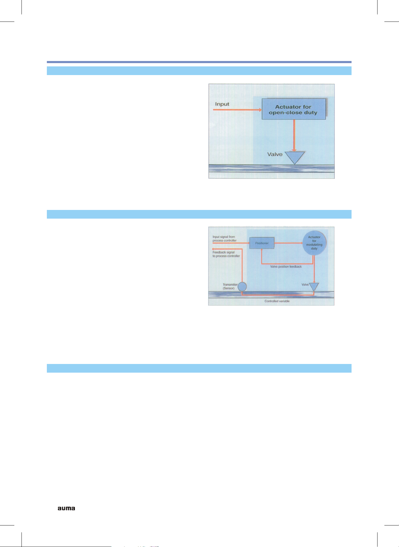
Open Close Duty
The characteristic feature of this actuator is
open loop. The normal valve positions in
OPEN-CLOSE Duty are end positions OPEN
and CLOSED. After receiving command, the
actuator operates the valve to one of the end
positions or if necessary to a preset
intermediate position. The valves are operated
relatively seldom, the time intervals can span
between a few minutes to several months.
Auma multi-turn actuators type SA for open
close service are rated for short time duty
S2-15min.
Regulating / Modulating Duty
Typical Characteristics of
OPEN-CLOSE DUTY
The characteristic feature of this actuator is
closed loop in which input command signal to
actuator is directly influenced by the flow
through the valve. Regulating / Modulating
duty actuator SAR operates between two set
bands between open-close positions depending
upon actual valve position and feedback signal.
The motors of these actuators are rated for
intermittent duty S4-25%. The mechanical
components and motor are designed to withstand
a large number of operations required for
modulating applications.
Typical Characteristics of
Regulating / Modulating Duty
Pemissible number of starts-stops depends upon
actuator size & speed. The details are available
in Data Sheets.
Short Time and Intermittent Duty IS 12824
Short time Duty S2 Intermittent Duty S4
Operation at constant load during a given
time, less than that required to reach thermal
equilibrium, followed by a rest and deenergized period of sufficient duration to reestablish machine temperatures within 2 C.
o
A sequence of identical duty cycles, each cycle
including a significant period of starting, a period
of operation at constant load and a rest and deenergized period. These periods being too short
to attain thermal equilibrium during one duty
cycle.
The duration of short time is limited to 15, 30
or 60 min.
The relative on time at S4-25% is limited to
25% of the cycle time.
8

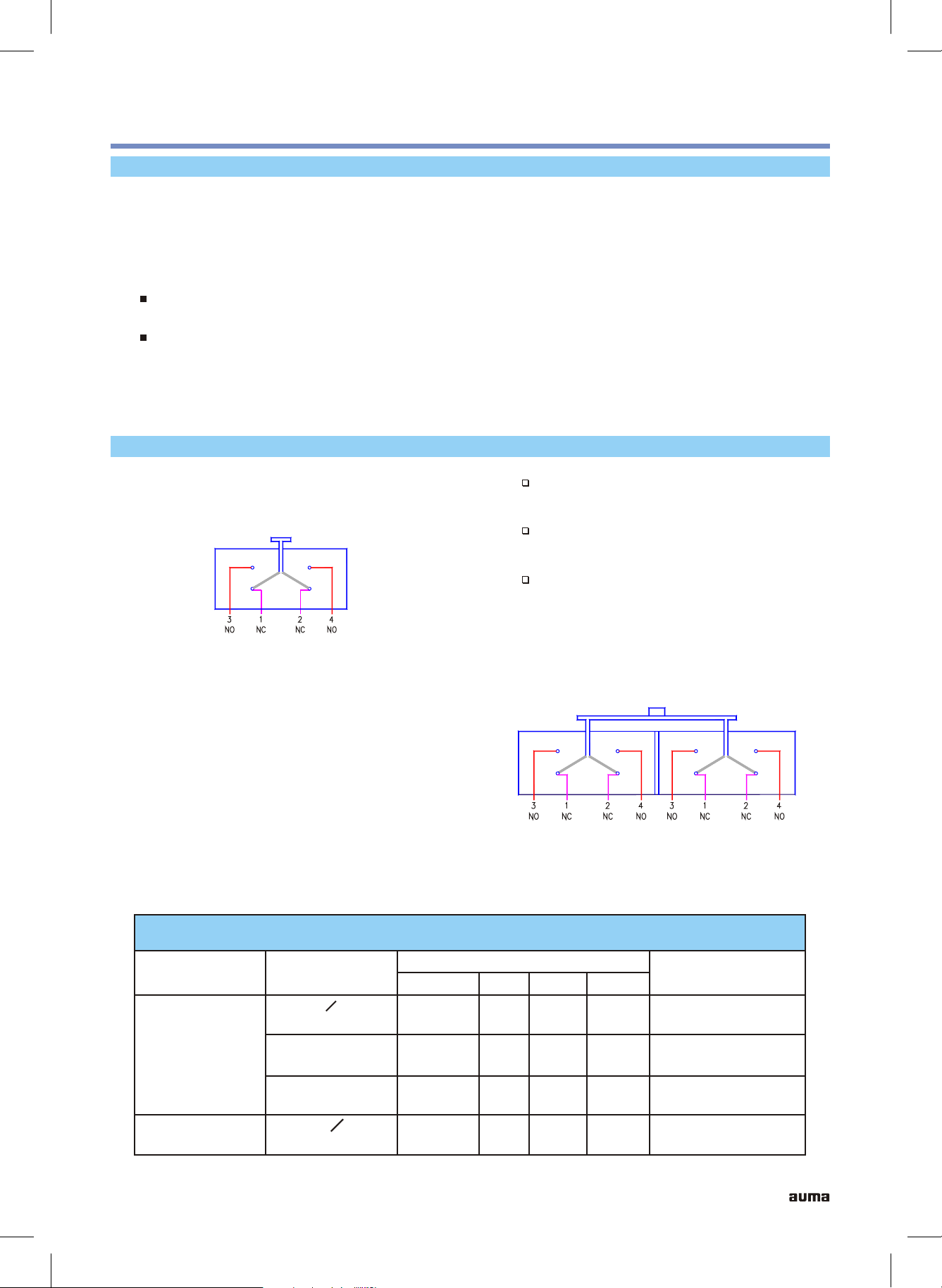
Limit Switching
Functions
The limit switching enables to switch off the
actuator when reaching defined valve
position, usually end positions. The valve
travel is measured by mechanical counter gear
mechanism which when reaching the set
Two Train Counter Gear
For Two train counter gear, two limit switches,
one for each direction of travel having 1 NO
+ 1 NC or 2 NO + 2 NC contacts are provided.
The number of spindle turns can be set
between 1 and 480 or 1 and 4800.
switching points operate the electrical limit
switches by cams. The setting accuracy is 1/10 of
a turn of actuator output shaft.
In limit switching, two train counter gear and
four train counter gear versions are available :
Four Train Counter Gear
If limit switching is required at two end
positions only, two train counter gear is used.
However, if two additional intermediate
switching positions are desired, Four Train
Counter Gear is required. This limit switching
has 4 counter gears and 4 micro switches. Two
counter gears are used to switch off at end
positions as in Two Train Counter Gear. The
other two are available for setting any desired
intermediate positions between end positions.
After cam actuation, the switches remain
actuated till reaching end of valve travel.
Examples of such application are :
To stop at intermediate position
Sequence control, that is to start
another equipment like pump or bypass
valve actuator after certain travel
of valve.
Two Train Counter Gear
The accuracy of setting is 1/10 of a turn of
actuator output shaft. For four train counter
gear, 4 limit switches of 1 NO + 1 NC or 2 NO
+ 2 NC contacts are provided.
Four Train Counter Gear
9
Functions
Torque Switching
The torque switching enables to switch off the
actuator when pre-determined torque is
reached instead of a defined position. The
torque switching works on principle of sliding
worm.
Axial displacement of worm proportional to
thrust is transmitted to torque switches.
Torque switches operate in closing & opening
directions. The required tripping torque can be
easily set on the graduated dial. If limit switch
cut off is selected prior to torque switch, then
torque switch serves as overload protection.
For tight seating of certain valves, the actuator
must be operated to end position CLOSED
with defined force. Such operation can be
carried out by torque seating. Limit seating is
commonly used in the end position OPEN.
Running Indication
Blinker switch is provided in the actuator and
can be used as running indicator.
Torque Switching
When torque seating is used at end position,
limit switches can be used for signalization.
Therefore actuator controls can differentiate
whether actuator was switched off by torque
switch or by limit switch. Micro switches of
torque switching are provided with 1 NO + 1 NC
or 2 NO + 2 NC contacts for both open & close
directions.
10
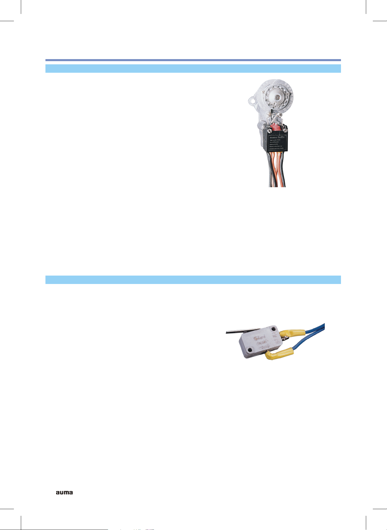
Micro Switches
Control Equipment
With the help of micro switches, mechanical
parameters such as travel & torque are
converted into electrical signals for actuator
control. There are four switches in the basic
version :
One limit switch each for the end
positions OPEN and CLOSE
One torque switch each for the
directions OPEN and CLOSE.
Single and Tandem Micro Switches
Limit and Torque Switches are available in
single or tandem versions.
Limit switches are tripped when an end position
is reached and torque switches are tripped when
the set tripping torque is exceeded.
The micro switches are sealed to enclosure
protection class IP66, as per IS 13947. The micro
switches have double break change over
potential free contacts. The circuit is interrupted
simultaneously at two points. The basic versions
of the switch contacts are of silver. For low
current ratings, micro switches with gold plated
contacts are available.
Switching another circuit also with
different voltage & current
Safety function, to operate with single
switch
Multiplying the available contacts,
example for signalization.
Single Micro Switch
Limit or Torque Switches in tandem version
have additional switching contacts. These
contacts can be wired for following applications :
Micro Switch Ratings
Type of Switch
Limit and
Torque
Type of
Current
AC, cos O = 0.8
Inductive
DC inductive
30 V
DC resistive
Blinker
AC, cos O = 0.8
Inductive
For such applications, a relay is recommended
since there may be small differences in tripping
points of tandem switches.
Rating in Amp at
75 V
8
5
7
7
1
1
Tandem Micro Switch
125 V 250 V
6
0.2
0.5
5
0.1
0.25
4
Approx. Electrical
contact rating
500,000 cycles at
250 V AC, 5A
50,000 cycles at
250 V DC, 0.1A
50,000 cycles at
250 V DC, 0.25A
11
Control Equipment
Reduction Gear Unit
A reduction gear unit (RGU) in the actuator is
used for mechanical position indication,
remote position indication & for operation of
intermediate switches. The output shaft of the
actuator drives final output shaft of RGU
through a series of reduction gears and final
shaft turns by approximately 270 while
o
actuator output shaft performs full number of
turns as set on two train or four train counter
gear unit. The reduction gear ratio needed for
each particular case is fitted at works if the
ratio is known. For this purpose fixed RGU
is supplied. If the ratio needs to be altered
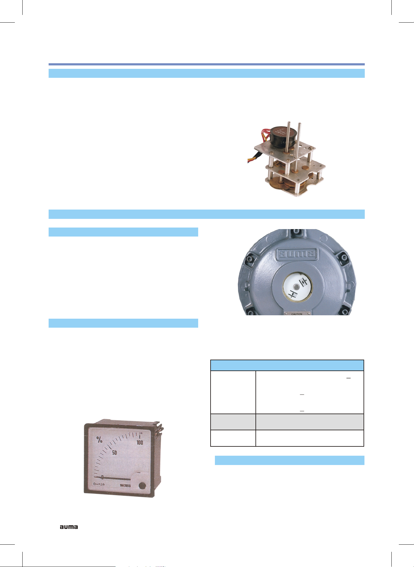
Position Indicators
Mechanical Position Indicator
The position of the valve is indicated
continuously by adjustable discs having
symbols for OPEN and CLOSE. The discs can
be seen through an indicator glass on switch
compartment cover. The open-close discs can
be set to coincide with limit switching. The
mechanical position indicator requires
reduction gear unit for operation.
at site, variable ratio RGU is available which
allows simple modification at site depending
upon number of turns of output shaft for full
stroke of valve.
Reduction Gear Unit (RGU)
Remote Position Indicator
The position of the valve can be transmitted as
a continuous signal for remote indication. A
potentiometer mounted on RGU is used for
this purpose. A power supply unit provides
necessary voltage to the potentiometer. The
potentiometer rotates through 270 for one full
o
stroke of valve & output signal from
potentiometer is proportional to valve travel.
Thus the actual position of the valve can be
Mechanical Position Indicator
read off continuously on position meter
calibrated & mounted on control panel.
Technical Data
Std: 220 ohms, 3W, Linearity + 3%
Optional : 100, 560, 1000 ohms,
Potentiometer
3W, Linearity + 3%
Precision : 200, 500, 1000 ohms,
1W, Linearity + 0.5%
Power
Supply Unit
Position
PS01, input 220V, 50Hz, output
24V DC
0 - 100% in various sizes
Meter
Digital Remote Position Indicator
Actual position display can be provided by
digital remote position indicator, which
displays open position in percentage.
12
Remote Position Indicator

Intermediate Switches
With this limit switching, additional switching
points can be set for each direction of rotation.
The switching can be set between 25 and 75%
of valve travel in each direction. The switch
sub assembly consisting of 2 or 4 cam switches
is mounted on output shaft of RGU. Each
micro switch has 1 NO + 1 NC contact.
Manual Operation
For commissioning or in an emergency when
there is no power supply, actuator can be
operated by hand wheel. The manual drive is
engaged by means of a lever. When motor
starts running, the manual drive gets
disengaged immediately & hand wheel does
not rotate during power operation.
Control Equipment
Intermediate Switches
In manual operation, hammer blow can be
effected with hand wheel. The hammer blow
makes it possible to open a jammed or rarely
operated valve.
Top Bevel Gear Set
Manual effort on hand wheel can be further
reduced by using a side mounted hand wheel
instead of standard hand wheel. Reduction
ratios available are
SA3 / 6 / 12 / 15
SA25 / 30 / 50 / 60
SA 100
Instead of hand wheel, a chain pulley can be
provided for actuators mounted in inaccessible
zones.
Space Heater
2 : 1
3 : 1
4 : 1
Top Bevel Gear Set
Condensation in the actuator is possible due to
wide fluctuation of the ambient temperature.
The heater integrated in the control unit
prevents the water condensation. The heater is
rated for continuous duty. This may be
continuously energized or when the actuator
is not operating.
Technical Data
Volts, AC
Resistance
ohms
Rating
Watts
230
5K
10 20 10 20
230 110 110
2.7K 1.2K 0.6K
13

Control Equipment
Motors
As a standard, Auma multi turn actuators are
equipped with 3 phase induction motors.
Auma motors are class F insulated and
withstand winding temperature upto 140 C.
o
The motors are used for short time duty (S2-15
min or S4-25% as per IS 12824) and provide
approximately three times rated torque for
short duration. The size of the motor is smaller
compared to continuous duty motor S1 of
same output power. This results in reduced
inertia of the rotor and therefore less
overshoot after switching off of motor. Auma
motors are designed for enclosure protection
class IP 68 when mounted on the actuator. All
motor cables are brought to terminal
compartment cover from inside of the actuator
thus avoiding terminal box.
Technical Data
Single Phase AC Motors
Auma actuators can be supplied with single
phase AC motor. The required capacitor is fitted
in the terminal compartment cover.
DC Motors
Auma actuators are also available with DC
motors. These motors operate on 24 V, 110 V or
220 V DC supply.
AC Motors with Other Voltages and
Frequency
Three phase induction motors are available in
wide range of operating voltages from 220 V to
560 V and operating frequency of 50 or 60 Hz.
3 ph AC Motor 1 ph AC Motor DC Motor
50/60 Hz : 220 V, 380 V
50/60 Hz :
400 V, 415 V
Voltages
440 V, 460 V
480 V, 500 V
550 V
Permissible Variation
in Voltage
+ 10%
Mounting C Type Flange, B14, IS 2223
Enclosure Protection IP 67 or IP 68 after mounting
Type of Cooling Surface Cooled
Insulation Class
F Class, IS 325 (max. temp. rise 140 C)
Starting Direct on line
Type of Duty S2-15 min. or S4-25 % IS 12824
Direction of Rotation Clockwise and anticlockwise
220 V - 240 V
110 V - 220 V
220 V
110 V
48 V
24 V
+ 10% + 10%
o
Motor Protection 3 thermo switches 2 thermo switches 4 thermo switches
14
Loading...