


SAEx 07.2
Table of contents
 Loading...
AUMA SAEx 07.2, SAEx 10.2, SAEx 07.6, SAEx 14.6, SAEx 16.2 Operation Instructions Manual
...
Multi-turn actuators
SAEx 07.2 – SAEx 16.2
SAREx 07.2 – SAREx 16.2
Control unit - electromechanical
with actuator controls
AUMATIC ACExC 01.2 Intrusive
Control
Parallel
Profibus DP
Modbus
Foundation Fieldbus
→ HART
Assembly, operation, commissioningOperation instructions

SAEx 07.2 – SAEx 16.2 / SAREx 07.2 – SAREx 16.2 Control unit - electromechanical
Table of contents ACExC 01.2 Intrusive HART
Read operation instructions first.
●
Observe safety instructions.
●
These operation instructions are part of the product.
●
Retain operation instructions during product life.
●
Pass on instructions to any subsequent user or owner of the product.
Purpose of the document:
This document contains information for installation, commissioning, operation and maintenance staff . It is intended
to support device installation and commissioning.
Reference documents:
●
Manual (Operation and setting) AUMATIC AC 01.2 HART
●
Manual (Device integration) AUMATIC AC 01.2 HART
Reference documents can be downloaded from the Internet (www.auma.com) or ordered directly from AUMA
(refer to <Addresses>).
Table of contents Page
112.2. Short description
123. Transport, storage and packaging........................................................................................
123.1. Transport
123.2. Storage
123.3. Packaging
134. Assembly................................................................................................................................
134.1. Mounting position
134.2. Handwheel fitting
134.3. Multi-turn actuator: mount to valve/gearbox
134.3.1. Output drive types B, B1 – B4 and E
144.3.1.1. Multi-turn actuator (with output drive types B1 – B4 or E): mount to valve/gearbox
144.3.2. Output drive type A
154.3.2.1. Stem nut: finish machining
164.3.2.2. Multi-turn actuator (with output drive type A): mount to valve
174.4. Accessories for assembly
174.4.1. Stem protection tube for rising valve stem
174.5. Mounting positions of local controls
184.5.1. Mounting positions: modify
51. Safety instructions.................................................................................................................
51.1. Basic information on safety
51.2. Range of application
61.3. Warnings and notes
71.4. References and symbols
82. Identification...........................................................................................................................
82.1. Name plate
195. Electrical connection.............................................................................................................
195.1. Basic information
215.2. Connecting via Ex plug/socket connector with screw-type terminals (KP, KPH)
215.2.1. Terminal compartment: open
215.2.2. Cable connection
2

SAEx 07.2 – SAEx 16.2 / SAREx 07.2 – SAREx 16.2 Control unit - electromechanical
ACExC 01.2 Intrusive HART Table of contents
235.2.3. Terminal compartment: close
245.3. Connecting via Ex plug/socket connector with terminal blocks (KES)
245.3.1. Terminal compartment: open
255.3.2. Cable connection
265.3.3. Terminal compartment: close
265.4. Accessories for electrical connection
265.4.1. Controls mounted to wall bracket
275.4.2. Parking frame
285.4.3. Protection cover
285.4.4. Earth connection, external
296. Operation................................................................................................................................
296.1. Manual operation
296.1.1. Manual operation: engage
296.1.2. Manual operation: disengage
296.2. Motor operation
296.2.1. Local actuator operation
306.2.2. Actuator operation from remote
306.3. Menu navigation via push buttons (for settings and indications)
316.3.1. Menu layout and navigation
326.4. User level, password
336.4.1. Password entry
336.4.2. Password change
346.5. Language in the display
346.5.1. Language change
367. Indications..............................................................................................................................
367.1. Indications during commissioning
367.2. Indications in the display
377.2.1. Feedback indications from actuator and valve
407.2.2. Status indications according to AUMA classification
417.2.3. Status indications according to NAMUR recommendation
427.3. Mechanical position indicator/running indication
437.4. Indication lights
448. Signals.....................................................................................................................................
448.1. Signals via HART
448.2. Status signals via output contacts (digital outputs)
448.2.1. Assignment of outputs
448.2.2. Encoding of outputs
448.3. Analogue signals
459. Commissioning (basic settings)...........................................................................................
459.1. Type of seating: set
469.2. HART address (slave address): set
479.3. Switch compartment: open
489.4. Torque switching: set
489.5. Limit switching: set
499.5.1. End position CLOSED (black section): set
499.5.2. End position OPEN (white section): set
509.6. Intermediate positions: set
509.6.1. Running direction CLOSE (black section): set
509.6.2. Running direction OPEN (white section): set
3

SAEx 07.2 – SAEx 16.2 / SAREx 07.2 – SAREx 16.2 Control unit - electromechanical
Table of contents ACExC 01.2 Intrusive HART
519.7. Test run
519.7.1. Direction of rotation: check
529.7.2. Limit switching: check
529.7.3. Reference operation position feedback: perform
539.8. Potentiometer
539.8.1. Potentiometer setting
539.9. Electronic position transmitter RWG
549.9.1. Measuring range: set
549.10. Mechanical position indicator: set
559.11. Switch compartment: close
5710. Corrective action....................................................................................................................
5710.1. Faults during commissioning
5710.2. Fault indications and warning indications
6010.3. Fuses
6010.3.1. Fuses within the actuator controls
6210.3.2. Motor protection (thermal monitoring)
6311. Servicing and maintenance...................................................................................................
6311.1. Preventive measures for servicing and safe operation
6311.2. Disconnection from the mains
6411.3. Maintenance
6511.4. Disposal and recycling
connector and screw-type terminals (KP, KPH)
minals (KP, KPH)
(KES)
6612. Technical data.........................................................................................................................
6612.1. Technical data Multi-turn actuators
6912.2. Technical data Actuator controls
7513. Spare parts.............................................................................................................................
7513.1. Multi-turn actuators SAEx 07.2 – SAEx 16.2/SAREx 07.2 – SAREx 16.2 with Ex plug/socket
7713.2. Actuator controls AUMATIC ACExC 01.2 with Ex plug/socket connector and screw-type ter-
7913.3. Actuator controls AUMATIC ACExC 01.2 with Ex plug/socket connector and terminal blocks
8114. Certificates..............................................................................................................................
8114.1. Declaration of Incorporation and EC Declaration of Conformity
8214.2. ATEX certificate
87Index........................................................................................................................................
89Addresses...............................................................................................................................
4

SAEx 07.2 – SAEx 16.2 / SAREx 07.2 – SAREx 16.2 Control unit - electromechanical
ACExC 01.2 Intrusive HART Safety instructions
1. Safety instructions
1.1. Basic information on safety Standards/directives
Safety instructions/warn-
ings
Qualification of staff
AUMA products are designed and manufactured in compliance with recognised
standards and directives.This is certified in a Declaration of Incorporation and an
EC Declaration of Conformity.
The end user or the contractor must ensure that all legal requirements, directives,
guidelines, national regulations and recommendations with respect to assembly,
electrical connection, commissioning and operation are met at the place of installation.
They include among others standards and directives such as IEC/EN 60079 “Electrical
apparatus for explosive atmospheres" –
●
Part 14: Electrical installations in hazardous areas (other than mines).
●
Part 17: Inspection and maintenance of electrical installations in hazardous
areas (other than mines).
All personnel working with this device must be familiar with the safety and warning
instructions in this manual and observe the instructions given. Safety instructions
and warning signs on the device must be observed to av oid personal injury or property
damage.
Assembly, electrical connection, commissioning, operation, and maintenance must
be carried out exclusively by suitab ly qualified personnel ha ving been authorised by
the end user or contractor of the plant only.
Prior to working on this product, the staff must have thoroughly read and understood
these instructions and, furthermore, know and observe officially recognised rules
regarding occupational health and safety.
Work performed in potentially explosiv e atmospheres is subject to special regulations
which have to be observed.The end user or contractor of the plant are responsible
for respect and control of these regulations, standards, and laws.
Commissioning
Operation
Protective measures
Maintenance
Prior to commissioning, it is important to check that all settings meet the requirements
of the application. Incorrect settings might present a danger to the application, e.g.
cause damage to the valve or the installation.The manufacturer will not be held
liable for any consequential damage. Such risk lies entirely with the user.
Prerequisites for safe and smooth operation:
●
Correct transport, proper storage, mounting and installation, as well as careful
commissioning.
●
Only operate the device if it is in perf ect condition while observing these instructions.
●
Immediately report any faults and damage and allow for corrective measures.
●
Observe recognised rules for occupational health and safety.
●
Observe the national regulations.
●
During operation, the housing warms up and surface temperatures > 60 °C may
occur.To prevent possible burns, we recommend checking the surf ace temperature using an appropriate thermometer and wearing protective gloves, if required, prior to working on the device.
The end user or the contractor are responsible for implementing required protective
measures on site, such as enclosures, barriers, or personal protective equipment
for the staff.
T o ensure saf e device operation, the maintenance instructions included in this manual
must be observed.
Any device modification requires prior consent of the manufacturer.
1.2. Range of application
AUMA multi-turn actuators are designed for the operation of industrial valves, e.g.
globe valves, gate valves, butterfly valves, and ball valves.
5
SAEx 07.2 – SAEx 16.2 / SAREx 07.2 – SAREx 16.2 Control unit - electromechanical
Safety instructions ACExC 01.2 Intrusive HART
The devices described below are approved for use in the potentially explosive
atmospheres of zones 1, 2, 21, and 22.
If temperatures >40 °C are to be expected at the valve mounting flange or the valve
stem (e.g. due to hot media), please consult AUMA.Temperatures > 40 °C are not
considered with regards to the non-electrical explosion protection.
Other applications require explicit (written) confirmation by the manufacturer.
The following applications are not permitted, e.g.:
●
Industrial trucks according to EN ISO 3691
●
Lifting appliances according to EN 14502
●
Passenger lifts according to DIN 15306 and 15309
●
Service lifts according to EN 81-1/A1
●
Escalators
●
Continuous duty
●
Buried service
●
Continuous submersion (observe enclosure protection)
●
Potentially explosive areas of zones 0 and 20
●
Potentially explosive areas of group I (mining)
●
Radiation exposed areas in nuclear power plants
No liability can be assumed for inappropriate or unintended use.
Observance of these operation instructions is considered as part of the device's
designated use.
Information
These operation instructions are only valid for the "clockwise closing" standard
version, i.e. driven shaft turns clockwise to close the valve.
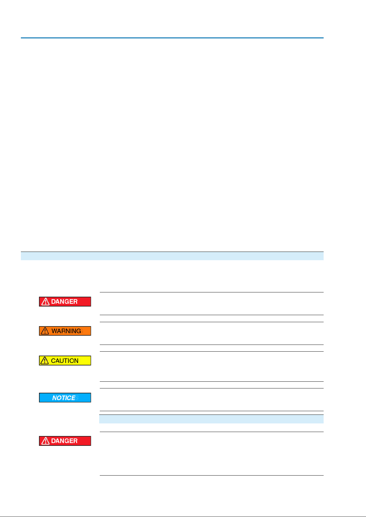
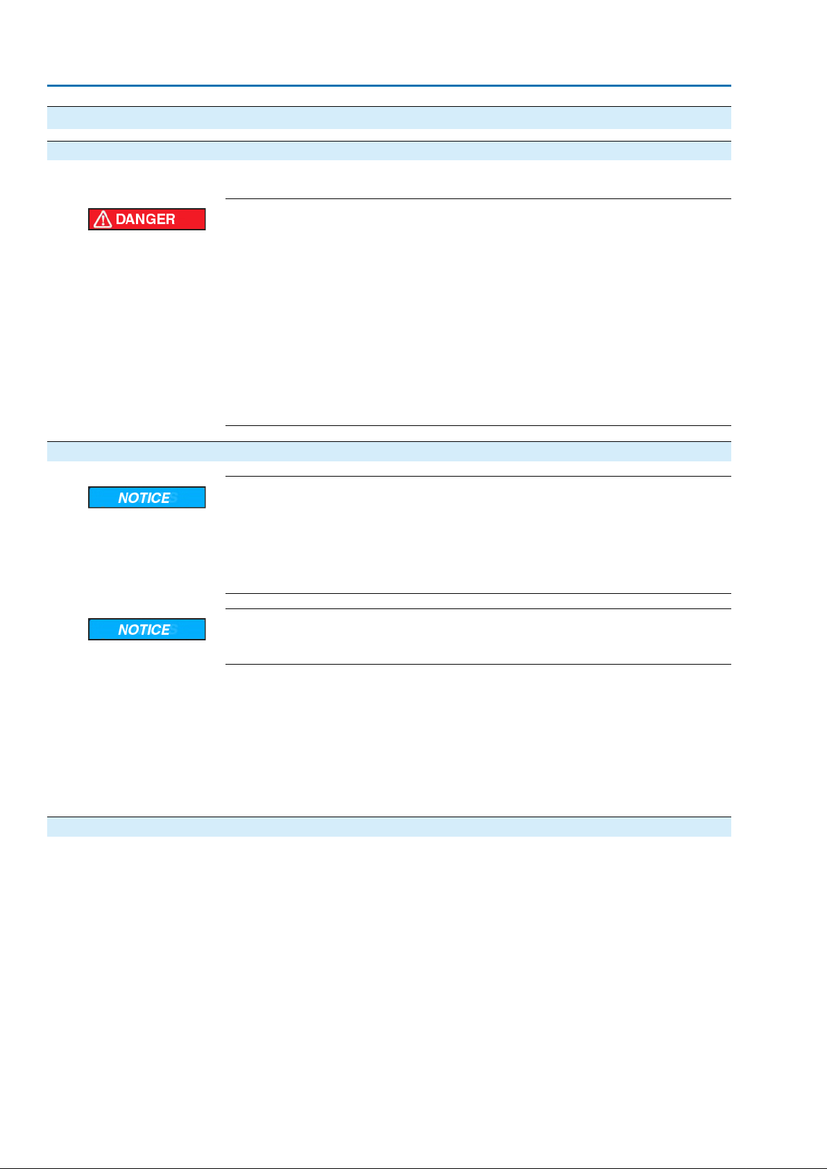
1.3. Warnings and notes
The following warnings draw special attention to saf ety-rele v ant procedures in these
operation instructions, each marked by the appropriate signal word (DANGER,
WARNING, CAUTION, NOTICE).
Indicates an imminently hazardous situation with a high level of risk. Failure
to observe this warning could result in death or serious injury.
Indicates a potentially hazardous situation with a medium level of risk. F ailure
to observe this warning could result in death or serious injury.
Indicates a potentially hazardous situation with a low level of risk. Failure to
observe this warning may result in minor or moderate injury . Ma y also be used
with property damage.
Potentially hazardous situation. Failure to observe this warning may result in
property damage. Is not used for personal injury.
Arrangement and typographic structure of the warnings
Type of hazard and respective source!
Potential consequence(s) in case of non-observance (option)
→
Measures to avoid the danger
→
Further measure(s)
6
SAEx 07.2 – SAEx 16.2 / SAREx 07.2 – SAREx 16.2 Control unit - electromechanical
ACExC 01.2 Intrusive HART Safety instructions
Safety alert symbol warns of a potential personal injury hazard.
The signal word (here: DANGER) indicates the level of hazard.
1.4. References and symbols
The following references and symbols are used in these instructions:
Information The term Information preceding the text indicates important notes and information.
Symbol for CLOSED (valve closed)
Symbol for OPEN (valve open)
Important information before the next step.This symbol indicates what is required
for the next step or what has to be prepared or observed.
Via the menu to parameter
Describes the path within the menu to the parameter. By using the push buttons of
the local controls you may quickly find the desired parameter in the display.
< > Reference to other sections
T erms in brack ets shown abov e refer to other sections of the document which provide
further information on this topic.These terms are either listed in the index, a heading
or in the table of contents and may quickly be found.
7
SAEx 07.2 – SAEx 16.2 / SAREx 07.2 – SAREx 16.2 Control unit - electromechanical
Identification ACExC 01.2 Intrusive HART
2. Identification
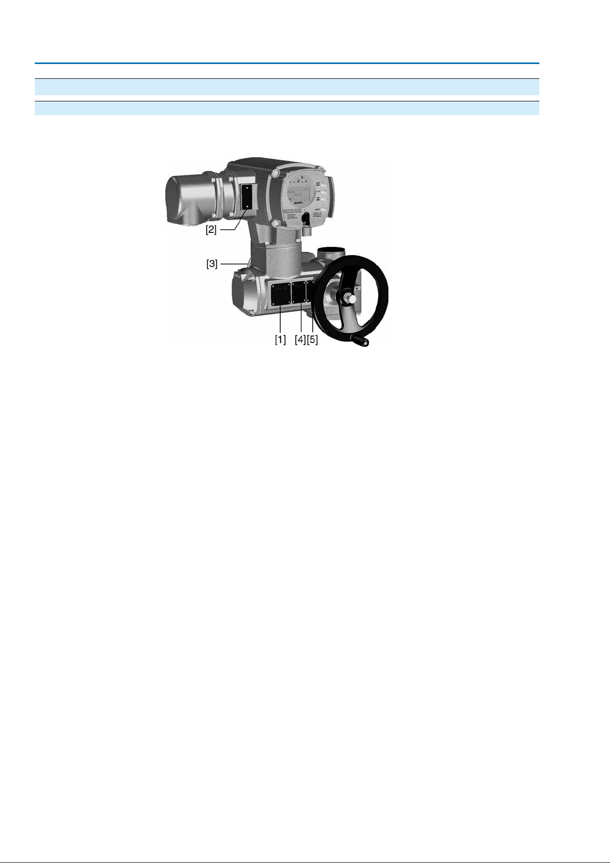
2.1. Name plate
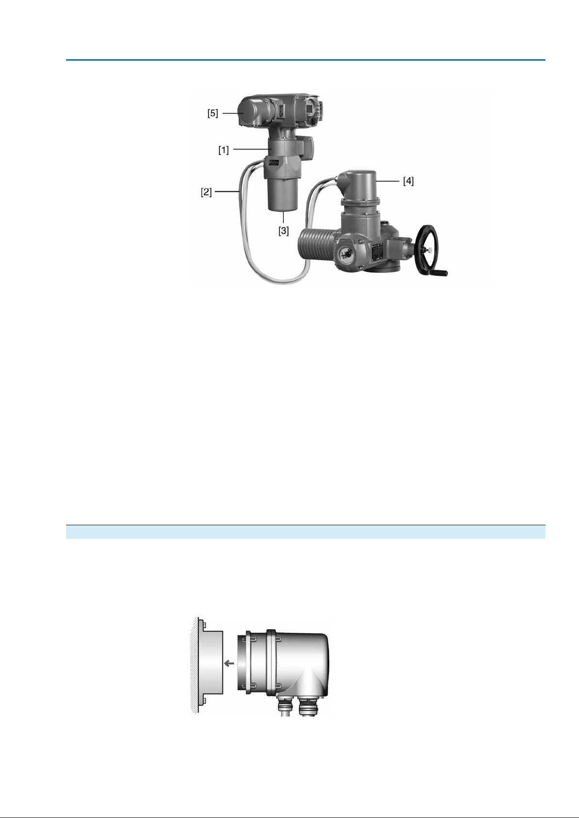
Each device component (actuator, controls, motor) is equipped with a name plate.
Figure 1: Arrangement of name plates
[1] Actuator name plate
[2] Actuator controls name plate
[3] Motor name plate
[4] Additional plate, e.g. KKS plate (Power Plant Classification System)
[5] Explosion protection approval plate
8

SAEx 07.2 – SAEx 16.2 / SAREx 07.2 – SAREx 16.2 Control unit - electromechanical
ACExC 01.2 Intrusive HART Identification
Actuator name plate
Figure 2: Actuator name plate (example)
[1] Name of manufacturer
[2] Address of manufacturer
[3] Type designation
[4] Order number
[5] Actuator serial number
[6] Speed
[7] Torque range in direction CLOSE
[8] Torque range in direction OPEN
[9] Type of lubricant
[10] Enclosure protection
[11] Permissible ambient temperature
[12] Can be assigned as an option upon customer request
[13] Can be assigned as an option upon customer request
[14] Data Matrix code
Actuator controls name plate
[1] Type designation
[2] Order number
[3] Serial number
[4] Actuator terminal plan
[5] Actuator controls terminal plan
[6] Mains voltage
[7] AUMA power class for switchgear
[8] Permissible ambient temperature
[9] Enclosure protection
[10] Control
[11] Data Matrix code
9

SAEx 07.2 – SAEx 16.2 / SAREx 07.2 – SAREx 16.2 Control unit - electromechanical
Identification ACExC 01.2 Intrusive HART
Descriptions
Type designation Figure 3:Type designation (example)
1. Type and size of actuator
2. Flange size
3. Ex marking
Type and size
These instructions apply to the following devices types and sizes:
SAEx 07.2, 07.6, 10.2, 14.2, 14.6, 16.2 = multi-turn actuators for open-close duty
SAREx 07.2, 07.6, 10.2, 14.2, 14.6, 16.2 = multi-turn actuators for modulating duty
ACExC 01.2 = AUMATIC actuator controls
Ex marking
Table 1: Marking for explosion protection (with example)
1b3a-/
1st position: Not used
–
2nd position: motor type
ADX or VDX: 3-phase AC motor
a
AEX, ACX, VEX and VCX: 1-phase AC motor
b
3rd position: protection type of electrical connection
Terminal compartment Ex e increased safety:
3
Types: KP, KPH or KES
Terminal compartment Ex d flameproof enclosure:
4
Type: KES-Exd
4th position: protection type of position transmitter
Without intrinsically safe electric circuita
Electric circuit Ex i Intrinsic safety:
b
Type: RWG 5020.2Ex
5th position: protection type of position transmitter
Standard fieldbus connection1
Ex nL non incendive fieldbus connection2
Ex ic intrinsically safe fieldbus connection3
Order number
The product can be identified using this number and the technical data as well as
order-related data pertaining to the device can be compiled.
Please always state this number for any product inquiries.
On the Internet at http://www.auma.com, we offer a service allowing authorised
users to download order-related documents such as wiring diagrams and technical
data (both in German and English), inspection certificates and the operation
instructions when entering the order number.
Serial number
10
Table 2: Description of serial number (with example)
MD123451405
1st+2nd position: Assembly in week
Week 0505
3rd+4th position:Year of production
Year of production: 201414
All other positions
Internal number for unambiguous product identificationMD12345
SAEx 07.2 – SAEx 16.2 / SAREx 07.2 – SAREx 16.2 Control unit - electromechanical
ACExC 01.2 Intrusive HART Identification
Actuator terminal plan
AUMA power class for
switchgear
Data Matrix code
9th position after TPA: Position transmitter version
0 = Without position transmitter
A, B, J, K, L, N, R,T = Potentiometer
C, D, E, G, H, M, P, S, U = Electronic position transmitter
The switchgear used in the actuator controls (reversing contactors/thyristors) are
classified according to AUMA power classes (e.g. A1, B1, ....).The power class
defines the max. permissible rated power (of the motor) the switchgear has been
designed for.The rated power (nominal power) of the actuator motor is indicated in
kW on the motor name plate. For the assignment of the AUMA po w er classes to the
nominal power of the motor types, refer to the separate electrical data sheets.
For switchgear without assignment to an y power classes, the actuator controls name
plate does not indicate the power class but the max. rated power in kW.
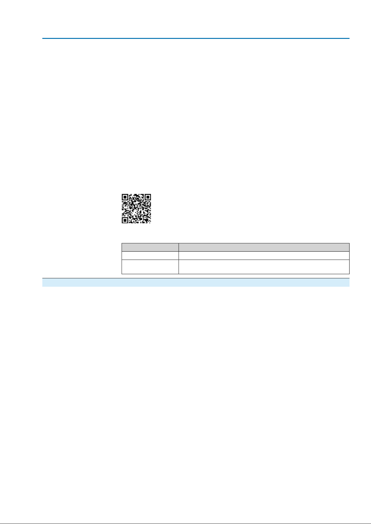
When registered as authorised user, you may use the AUMA Support App to scan
the Data Matrix code and directly access the order-related product documents without
having to enter order number of serial number.
Figure 4: Link to the App store:
Control
2.2. Short description
Multi-turn actuator
Actuator controls
Local con-
trols/AUMA CDT
Intrusive - Non-Intrusive
Table 3: Control examples (indications on controls name plate)
DescriptionInput signal
Control via HART interfaceHART
HART/24 V DC
Control via HART interface and control voltage for OPEN - CLOSE
Control via digital inputs (OPEN, STOP, CLOSE)
Definition in compliance with EN ISO 5210:
A multi-turn actuator is an actuator which transmits to the valve a torque for at least
one full revolution. It is capable of withstanding thrust.
AUMA multi-turn actuators are driven by an electric motor and are capable of
withstanding thrust in combination with output drive type A. For manual operation,
a handwheel is provided. Switching off in end positions may be either by limit or
torque seating. Controls are required to operate or process the actuator signals.
The AUMATIC actuator controls are used to operate AUMA actuators and are supplied
ready for use.The controls may be mounted directly to the actuator or separately
on a wall bracket.
When set to local control, it is possible to
●
operate the actuator via the local controls (push buttons and display) and perf orm
settings (contents of these instructions).
●
read in or out data or modify and save settings via the AUMA CDT software
(accessories), using a computer (laptop or PC).The connection between computer and AUMATIC is wireless via Bluetooth interface (not included in these
instructions).
●
Intrusive version (control unit: electromechanical):
Limit and torque setting is performed via switches in the actuator.
●
Non-Intrusive version (control unit: electronic):
Limit and torque setting is performed via the controls, actuator and controls
housings do not have to be opened. For this purpose, the actuator is equipped
with an MWG (magnetic limit and torque transmitter), also supplying analogue
torque feedback signals/torque indication and analogue position feedback signals/position indication.
11
SAEx 07.2 – SAEx 16.2 / SAREx 07.2 – SAREx 16.2 Control unit - electromechanical
Transport, storage and packaging ACExC 01.2 Intrusive HART
3. Transport, storage and packaging
3.1. Transport
For transport to place of installation, use sturdy packaging.
Hovering load!
Risk of death or serious injury.
→
Do NOT stand below hovering load.
→
Attach ropes or hooks for the purpose of lifting by hoist only to housing and NOT
to handwheel.
→
Actuators mounted on valves: Attach ropes or hooks for the purpose of lifting
by hoist to valve and NOT to actuator.
→
Actuators mounted to gearboxes: Attach ropes or hooks f or the purpose of lifting
by hoist only to the gearbox using eyebolts and NOT to the actuator.
→
Actuators mounted to controls: Attach ropes or hooks for the purpose of lifting
by hoist only to the actuator and NOT to the controls.
3.2. Storage
Long-term storage
3.3. Packaging
Danger of corrosion due to inappropriate storage!
→
Store in a well-ventilated, dry room.
→
Protect against floor dampness by storage on a shelf or on a wooden pallet.
→
Cover to protect against dust and dirt.
→
Apply suitable corrosion protection agent to uncoated surfaces.
Damage on display caused by temperatures below permissible level!
→
The AUMATIC actuator controls must NOT be stored below –30 °C.
If the device must be stored for a long period (more than 6 months) the following
points must be observed in addition:
1. Prior to storage:
Protect uncoated surfaces, in particular the output drive parts and mounting
surface, with long-term corrosion protection agent.
2. At an interval of approx. 6 months:
Check for corrosion. If first signs of corrosion show , apply ne w corrosion protection.
Our products are protected by special packaging for transport when leaving the
factory .The packaging consists of environmentally friendly materials which can easily
be separated and recycled.We use the following packaging materials: wood,
cardboard, paper, and PE foil. For the disposal of the packaging material, we
recommend recycling and collection centres.
12
SAEx 07.2 – SAEx 16.2 / SAREx 07.2 – SAREx 16.2 Control unit - electromechanical
ACExC 01.2 Intrusive HART Assembly
4. Assembly
4.1. Mounting position
AUMA actuators and actuator controls can be operated without restriction in any
mounting position.
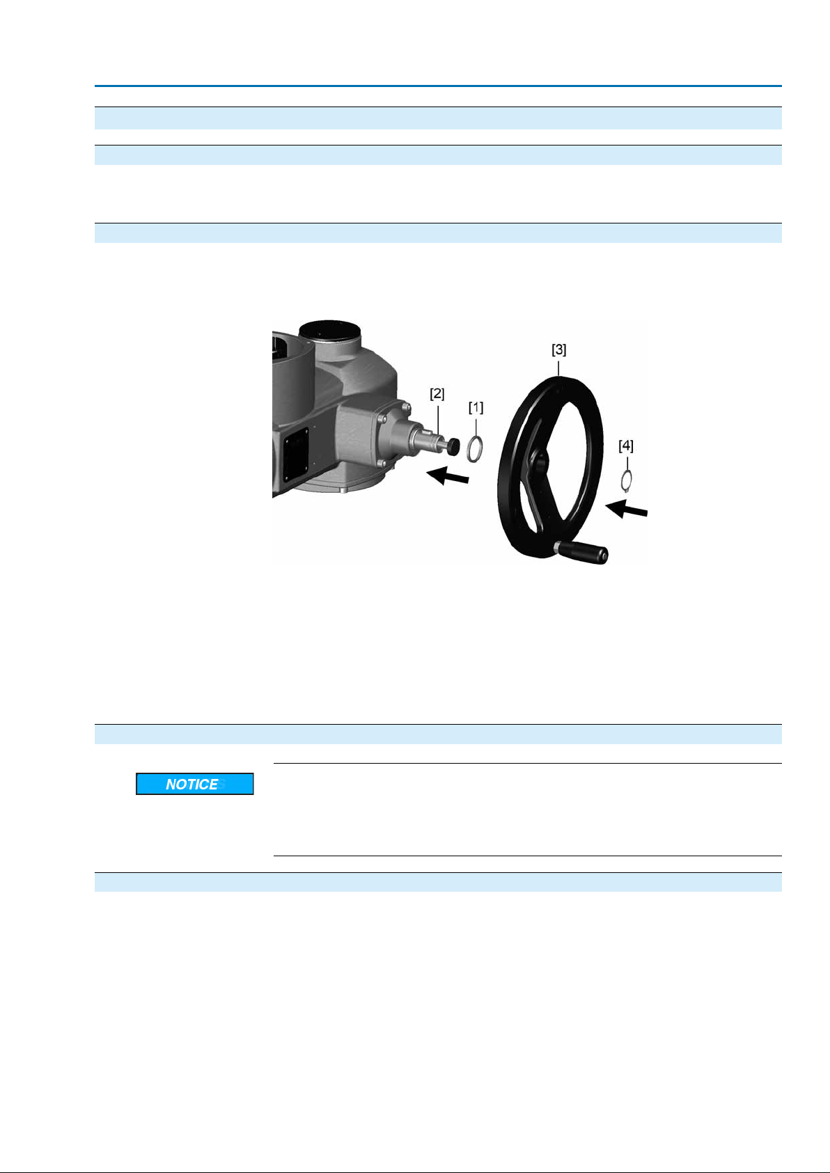
4.2. Handwheel fitting
Information For transport purposes, handwheels from a diameter of 400 mm are supplied separ-
ately.
Figure 5: Handwheel
[1] Spacer
[2] Input shaft
[3] Handwheel
[4] Circlip
1. If required, fit spacer [1] onto input shaft [2].
2. Slip handwheel [3] onto input shaft.
3. Secure handwheel [3] using the circlip [4] supplied.
4.3. Multi-turn actuator: mount to valve/gearbox
Danger of corrosion due to damage to paint finish and condensation!
→
Touch up damage to paint finish after work on the device.
→
After mounting, connect the device immediately to electrical mains to ensure
that heater minimises condensation.
4.3.1. Output drive types B, B1 – B4 and E
●
Application
Design
For rotating, non-rising valve stem
●
Not capable of withstanding thrust
Output drive bore with keyway:
●
Types B1 – B4 with bore according to EN ISO 5210
●
Types B and E with bore according to DIN 3210
●
Later change from B1 to B3, B4, or E is possible.
13
SAEx 07.2 – SAEx 16.2 / SAREx 07.2 – SAREx 16.2 Control unit - electromechanical
Assembly ACExC 01.2 Intrusive HART
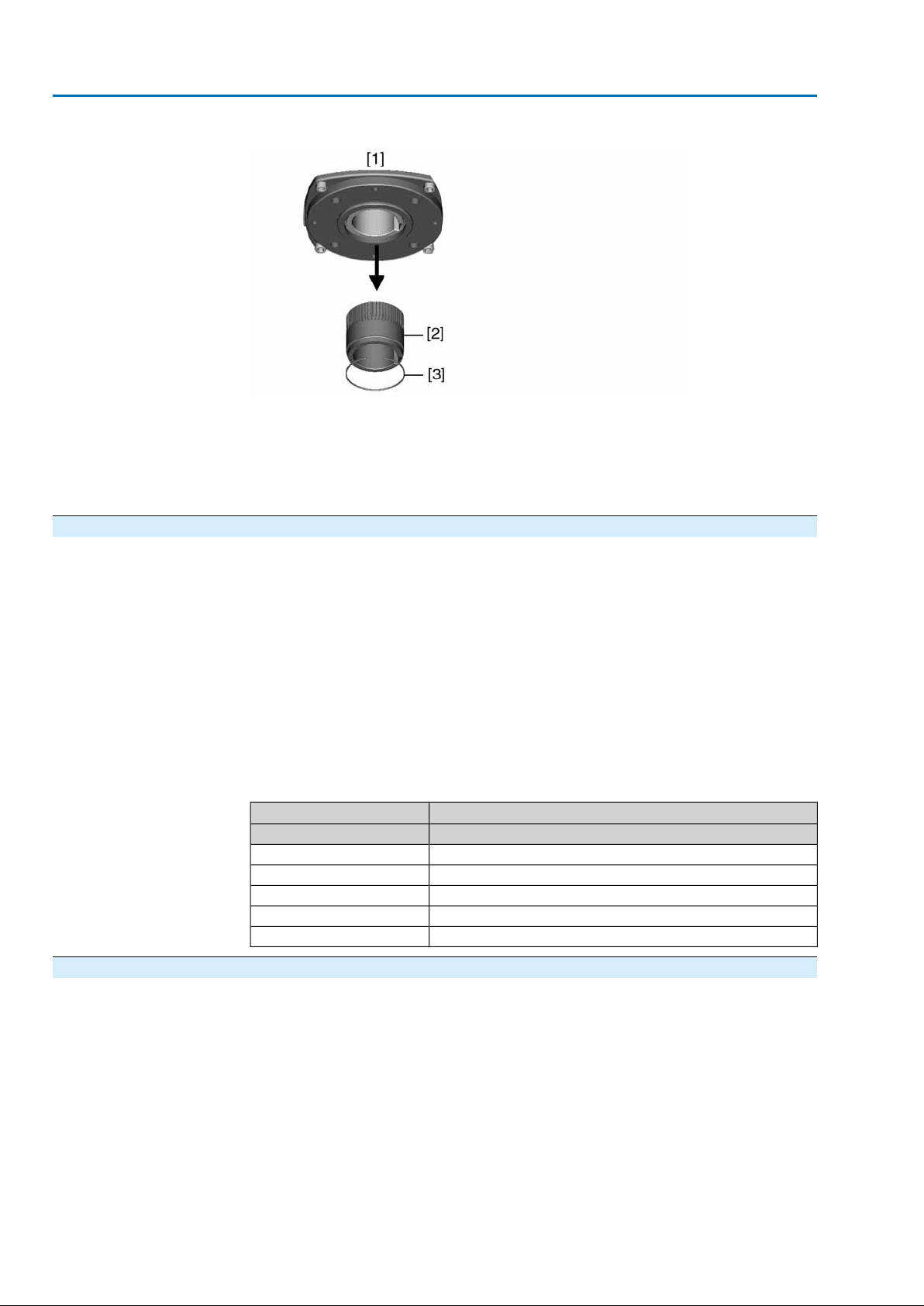
Figure 6: Output drive
[1] Output drive types B, B1 – B4, E and C
[2] Output drive sleeve/output drive plug sleve with bore and keyway
[3] Circlip
Information Spigot at flanges should be loose fit.
4.3.1.1. Multi-turn actuator (with output drive types B1 – B4 or E): mount to valve/gearbox
1. Check if mounting flanges fit together.
2. Check whether bore and keyway match the input shaft.
3. Apply a small quantity of grease to the input shaft.
4. Place multi-turn actuator.
Information: Ensure that the spigot fits uniformly in the recess and that the
mounting faces are in complete contact.
5. Fasten multi-turn actuator with screws according to table.
Information: We recommend applying liquid thread sealing material to the
screws to avoid contact corrosion.
6. Fasten screws crosswise to a torque according to table.
Table 4: Tightening torques for screws
Tightening torque TA [Nm]Screws
Strength class 8.8Threads
25M8
51M10
87M12
214M16
431M20
4.3.2. Output drive type A
●
Application
Output drive for rising, non-rotating valve stem
●
Capable of withstanding thrust
Information To adapt the actuators to output drive types A av ailab le on site with flanges F10 and
F14 (year of manufacture: 2009 and earlier), an adapter is required.The adapter
can be ordered from AUMA.
14

SAEx 07.2 – SAEx 16.2 / SAREx 07.2 – SAREx 16.2 Control unit - electromechanical
ACExC 01.2 Intrusive HART Assembly
4.3.2.1. Stem nut: finish machining
This working step is only required if stem nut is supplied unbored or with pilot
✔
bore.
Figure 7: Design of output drive type A
[1] Stem nut
[2] Bearing
[2.1] Bearing race
[2.2] Bearing rim
[3] Spigot ring
1. Remove spigot ring [3] from output drive.
2. Remove stem nut [1] together with bearings [2].
3. Remove bearing races [2.1] and bearing rims [2.2] from stem nut [1].
4. Drill and bore stem nut [1] and cut thread.
Information: When fixing in the chuck, make sure stem nut runs true!
5. Clean the machined stem nut [1].
6. Apply sufficient Lithium soap EP multi-purpose grease to bearing rims [2.2] and
bearing races [2.1], ensuring that all hollow spaces are filled with grease.
7. Place greased bearing rims [2.2] and bearing races [2.1] onto stem nut [1].
8. Re-insert stem nut [1] with bearings [2] into output drive.
Information:Ensure that dogs or splines are placed correctly in the keyway of
the hollow shaft.
9. Screw in spigot ring [3] until it is firm against the shoulder.
15
SAEx 07.2 – SAEx 16.2 / SAREx 07.2 – SAREx 16.2 Control unit - electromechanical
Assembly ACExC 01.2 Intrusive HART
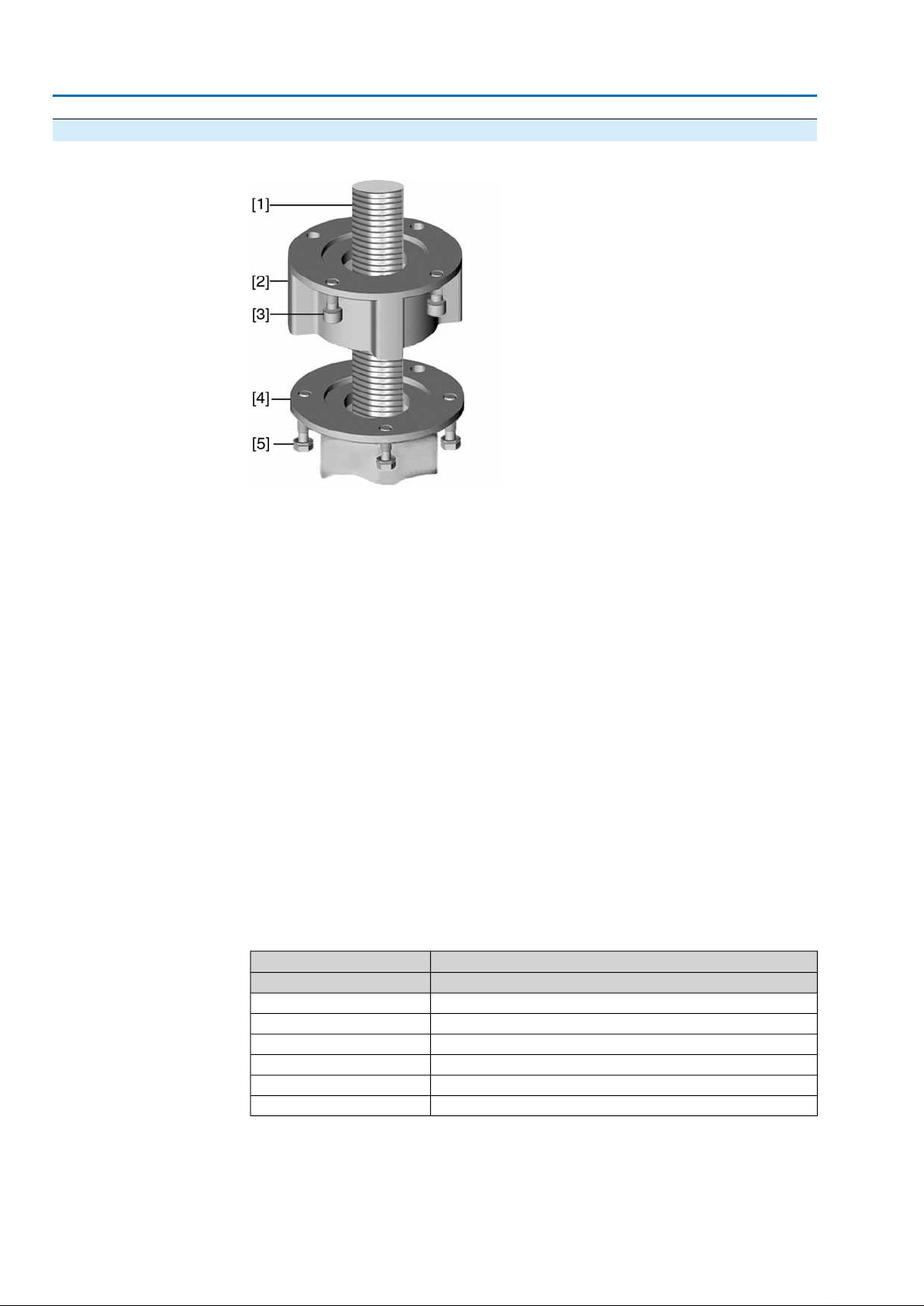
4.3.2.2. Multi-turn actuator (with output drive type A): mount to valve
Figure 8: Assembly with output drive type A
[1] Valve stem
[2] Output drive type A
[3] Screws to actuator
[4] Valve flange
[5] Screws to output drive
1. If the output drive type A is already mounted to the multi-turn actuator: Loosen
screws [3] and remove output drive type A [2].
2. Check if the flange of output drive type A matches the valve flange [4].
3. Apply a small quantity of grease to the valve stem [1].
4. Place output drive type A on valve stem and turn until it is flush on the valve
flange.
5. Turn output drive type A until alignment of the fixing holes.
6. Screw in fastening screws [5], however do not completely tighten.
7. Fit multi-turn actuator on the valve stem so that the stem nut dogs engage into
the output drive sleeve.
The flanges are flush with each other if properly engaged.
➥
8. Adjust multi-turn actuator until alignment of the fixing holes.
9. Fasten multi-turn actuator with screws [3].
10. Fasten screws [3] crosswise with a torque according to table.
Table 5: Tightening torques for screws
Tightening torque TA [Nm]Screws
Strength class 8.8Threads
11M6
25M8
51M10
87M12
214M16
431M20
11. Turn multi-turn actuator with handwheel in direction OPEN until valve flange
and output drive A are firmly placed together.
12. Tighten fastening screws [5] between valve and output drive type A crosswise
applying a torque according to table.
16
SAEx 07.2 – SAEx 16.2 / SAREx 07.2 – SAREx 16.2 Control unit - electromechanical
ACExC 01.2 Intrusive HART Assembly
4.4. Accessories for assembly
4.4.1. Stem protection tube for rising valve stem — Option —
Figure 9: Assembly of the stem protection tube
[1] Cap for stem protection tube
[2] Stem protection tube
[3] Sealing ring
1. Seal thread with hemp, Teflon tape, or thread sealing material.
2. Screw stem protection tube [2] into thread and tighten it firmly.
3. Push down the sealing ring [3] onto the housing.
4. Check whether cap for stem protection tube [1] is available and in perfect con-
dition.
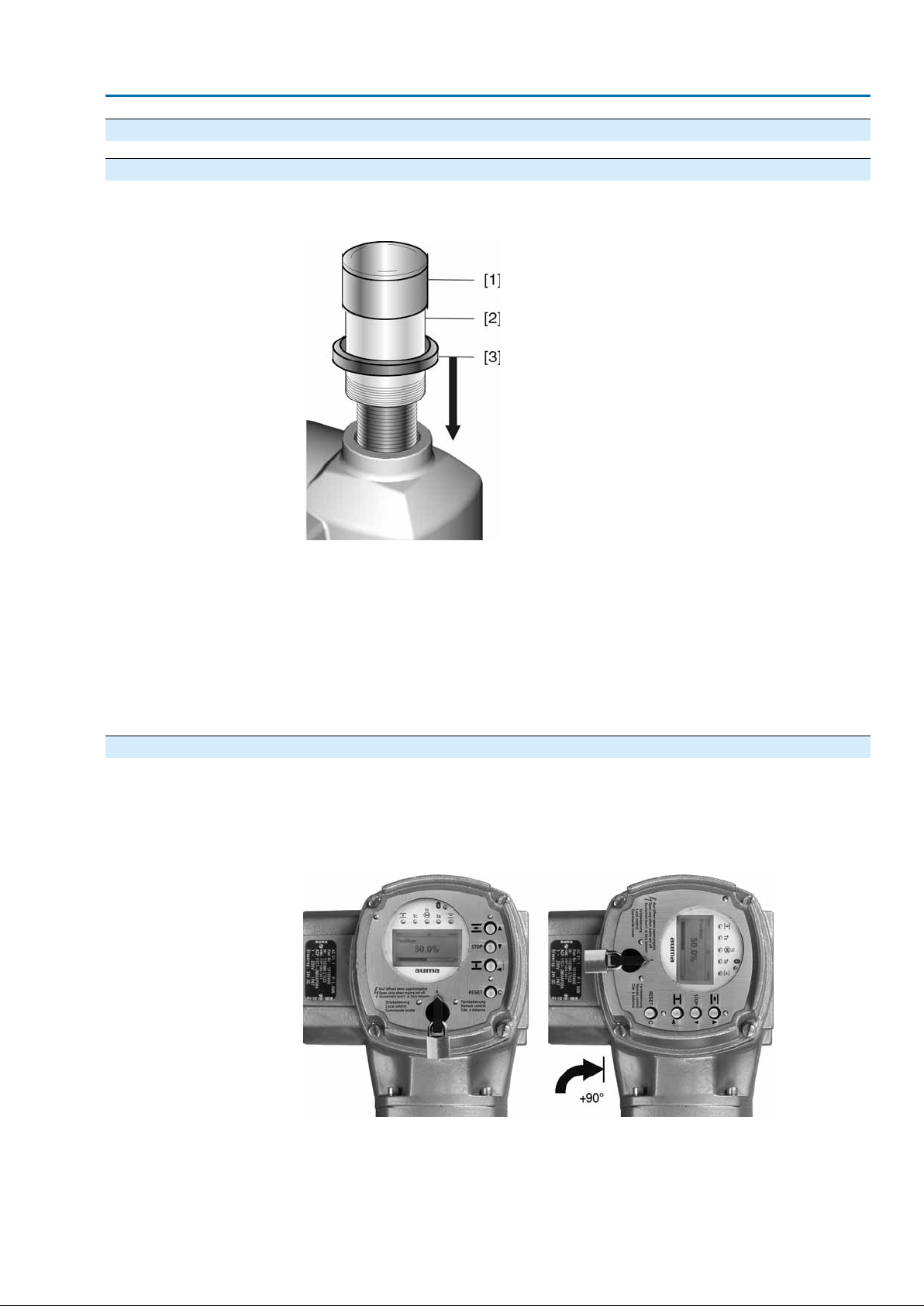
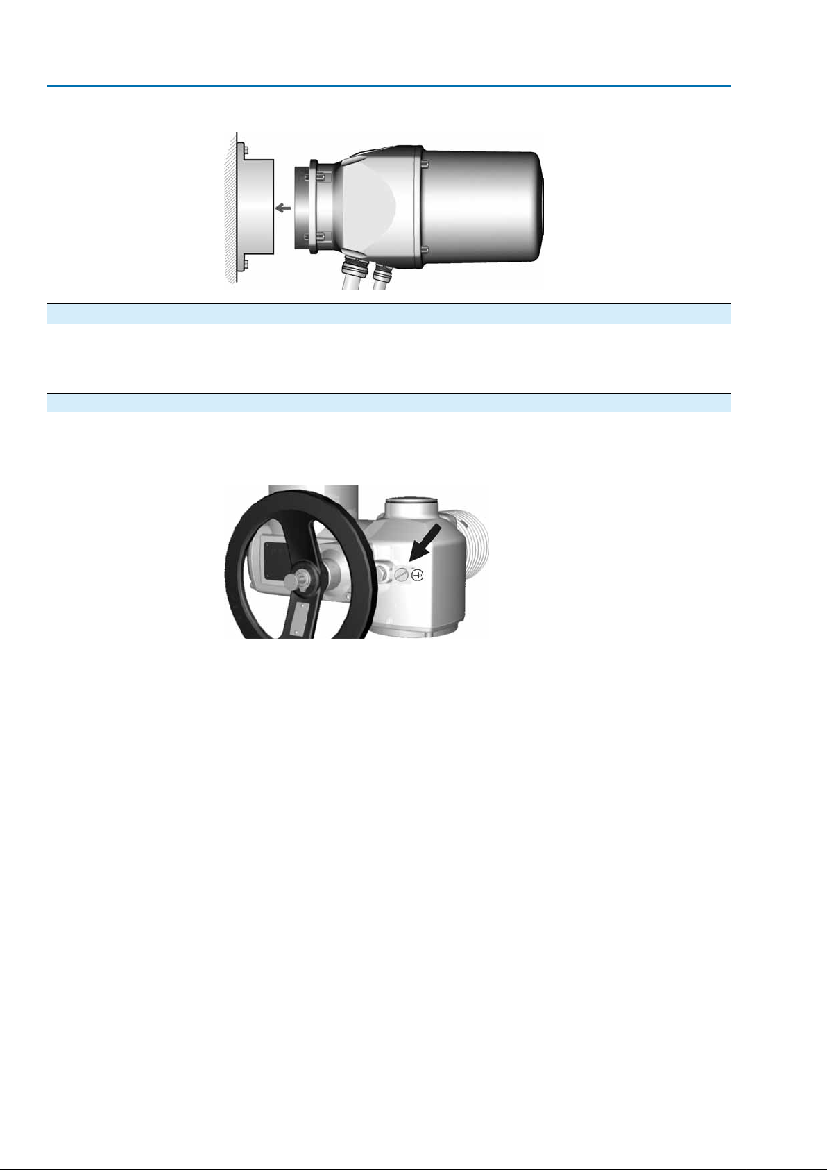
4.5. Mounting positions of local controls
The mounting position of the local controls is selected according to the order. If , after
mounting the actuator to the valve or the gearbox on site, the local controls are in
an unfav ourable position, the mounting position can be changed at a later date . F our
mounting positions are possible.
Figure 10: Mounting positions A and B
17
SAEx 07.2 – SAEx 16.2 / SAREx 07.2 – SAREx 16.2 Control unit - electromechanical
Assembly ACExC 01.2 Intrusive HART
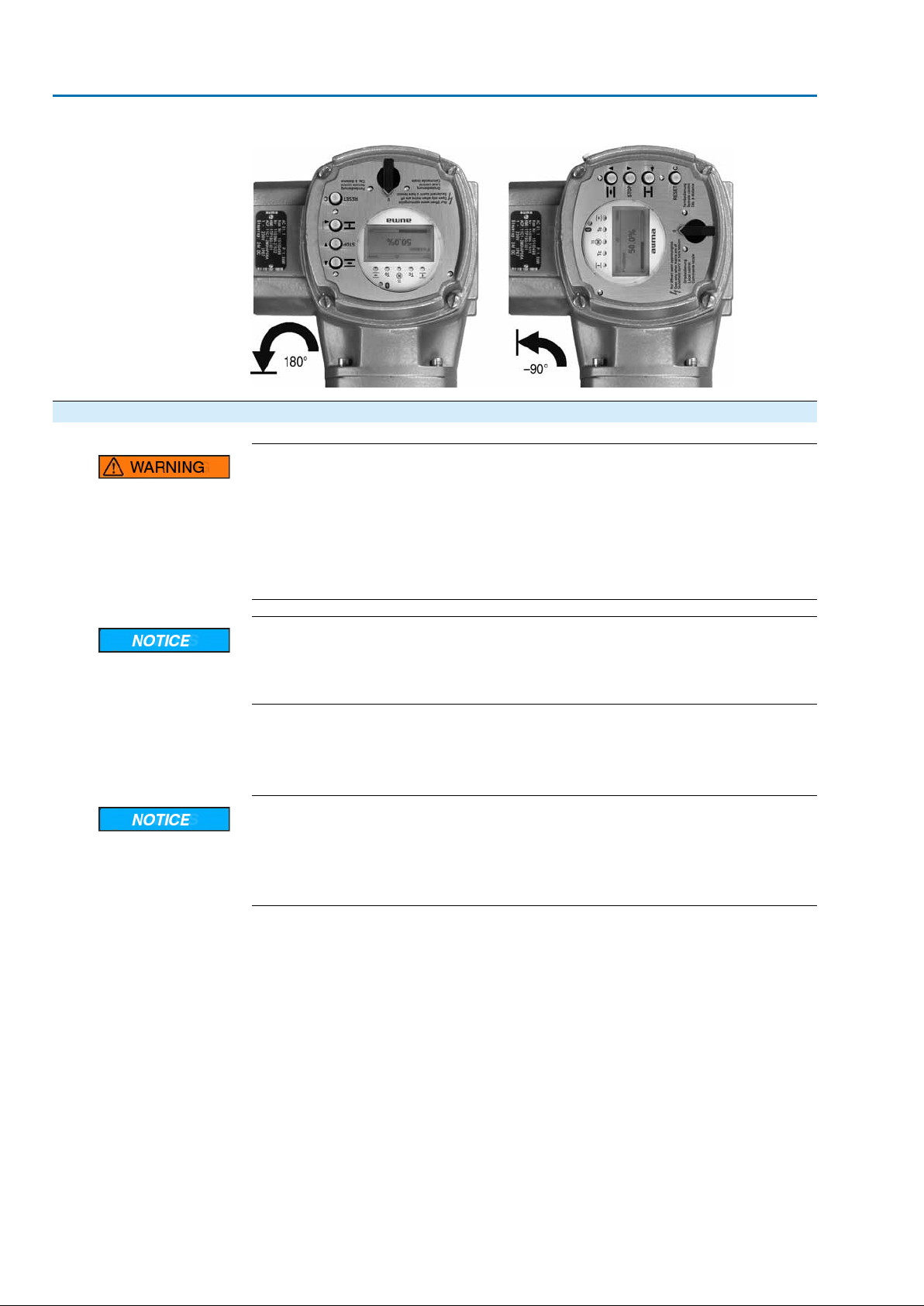
Figure 11: Mounting positions C and D
4.5.1. Mounting positions: modify
Flameproof enclosure, danger of explosion!
Risk of death or serious injury.
→
Before opening, ensure that there is no explosive gas and no voltage.
→
Handle cover and housing parts with care.
→
Joint surfaces must not be damaged or soiled in any way.
→
Do not jam cover during fitting.
Electrostatic discharge ESD!
Risk of damage to electronic components.
→
Earth both operators and devices.
1. Loosen screws and remove the local controls.
2. Check whether O-ring is in good condition, correctly insert O-ring.
3. Turn local controls into new position and re-place.
Cable damage due to twisting or pinching!
Risk of functional failures.
→
Turn local controls by a maximum of 180°.
→
Carefully assemble local controls to avoid pinching the cables.
4. Fasten screws evenly crosswise.
18

SAEx 07.2 – SAEx 16.2 / SAREx 07.2 – SAREx 16.2 Control unit - electromechanical
ACExC 01.2 Intrusive HART Electrical connection
5. Electrical connection
5.1. Basic information
Danger due to incorrect electrical connection
Failure to observe this warning can result in death, serious injury , or property damage.
→
The electrical connection must be carried out exclusively by suitably qualified
personnel.
→
Prior to connection, observe basic information contained in this chapter.
→
After connection but prior to applying the voltage, observe the <Commissioning>
and <Test run> chapters.
Wiring diagram/terminal
plan
Permissible networks
(supply networks)
Protection on site
The pertaining wiring diagram/terminal plan (both in German and English) is attached
to the device in a weather-proof bag, together with these operation instructions. It
can also be requested from AUMA (state order number, refer to name plate) or
downloaded directly from the Internet (http://www.auma.com).
The controls (actuators) are suitable for for use in TN and TT networks with directly
earthed star point and a maximum voltage of 690 V AC. Use in IT networks is
permitted while observing the respective <Protection on site> for for maiximum supply
voltages of 600 V AC.
For short-circuit protection and for disconnecting the actuator from the mains, fuses
and disconnect switches have to be provided by the customer.
The current values for respective sizing is derived from the current consumption of
the motor (refer to electrical data sheet) plus the current consumption of the controls.
Table 6: Current consumption controls
Max. current consumptionMains voltage
–30 %±10 %Permissible variation of the mains voltage
1,200 mA750 mA100 to 120 V AC
750 mA400 mA208 to 240 V AC
400 mA250 mA380 to 500 V AC
400 mA200 mA515 to 690 V AC
Power supply for the
controls (electronics)
Safety standards
Table 7: Maximum permissible protection
Max. protectionRated powerSwitchgear
16 A (gL/gG)up to 1.5 kWReversing contactor A1
32 A (gL/gG)up to 7.5 kWReversing contactor A2
63 A (gL/gG)up to 11 kWReversing contactor A3
16 A (g/R) I²t<1,500A²sup to 1.5 kWThyristor B1
32 A (g/R) I²t<1,500A²sup to 3 kWThyristor B2
63 A (g/R) I²t<5,000A²sup to 5.5 kWThyristor B3
If controls are mounted separately from actuator (controls on wall brack et): Consider
length and cross section of connecting cable when defining the protection required.
Use appropriate insulation monitors when working in power installations, for e xample
an insulation monitor measuring the pulse code.
In case of external supply of the controls (electronics):The external power supply
must have a reinforced insulation against the mains voltage in accordance with IEC
61010-1 and may only be supplied by a circuit limited to 150 VA in accordance with
IEC 61010-1.
All externally connected devices shall comply with the relevant safety standards.
19
SAEx 07.2 – SAEx 16.2 / SAREx 07.2 – SAREx 16.2 Control unit - electromechanical
Electrical connection ACExC 01.2 Intrusive HART
Cable installation in ac-
cordance with EMC
Type of current, mains
voltage and mains fre-
quency
Signal and bus cables are susceptible to interference.
Motor cables are interference sources.
●
Lay cables being susceptible to interference or sources of interference at the
highest possible distance from each other.
●
The interference immunity of signal and bus cables increases if the cables are
laid close to the earth potential.
●
If possible, avoid laying long cables and make sure that they are installed in
areas being subject to low interference.
●
Avoid long par allel paths with cab les being either susceptible to interf erence or
interference sources.
●
For the connection of remote position transmitters, screened cables must be
used.
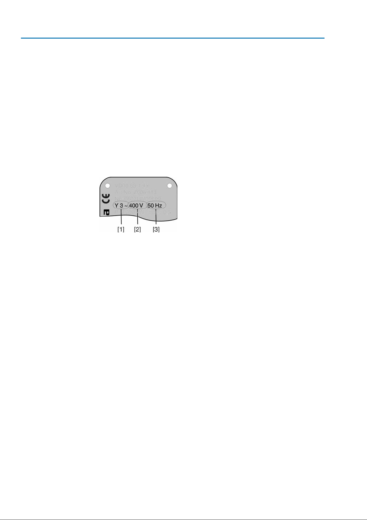
Type of current, mains voltage and mains frequency must match the data on the
motor name plate.
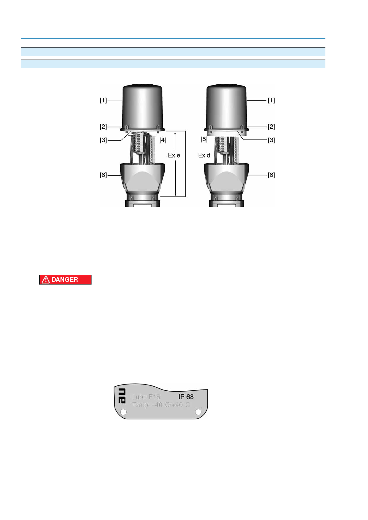
Figure 12: Motor name plate (example)
Connecting cables
HART cable recommend-
ation:
[1] Type of current
[2] Mains voltage
[3] Mains frequency (for 3-ph and 1-ph AC motors)
●
For device insulation, appropriate (v oltage-proof) cables must be used. Specify
cables for the highest occurring rated voltage.
●
Use connecting cables with a minimum temperature range of +80 °C.
●
For connecting cables exposed to UV radiation (outdoor installation), use UV
resistant cables.
Twisted wire pair, shielded.
For cable length <1 500 m: cross section min. 0.2 mm²
For cable length <1 500 m: cross section min. 0.5 mm²
We recommend selecting 0.75 mm² cross section. For smaller cable length cross
section, the cross section must be enlarged to min. 0.75 mm² using a wire end sleeve
if required and performing an appropriate concentric crimping.
Multiple-twisted pair cables must not be used.
Prior to installation, please note:
●
Connection is made as point-to-point topology.
●
Respect a distance of minimum 20 cm between HART cab les and other cables
if possible. If possible, the cab les should be laid in a separ ate , conductive, and
earthed cable tray.
●
Make sure that there are no potential differences between participants.
●
Maximum cable length depends on characteristics of devices connected (impedance), of cables used (cable capacity and resistance) and the impedance
of all devices installed between two end devices.
20
SAEx 07.2 – SAEx 16.2 / SAREx 07.2 – SAREx 16.2 Control unit - electromechanical
ACExC 01.2 Intrusive HART Electrical connection
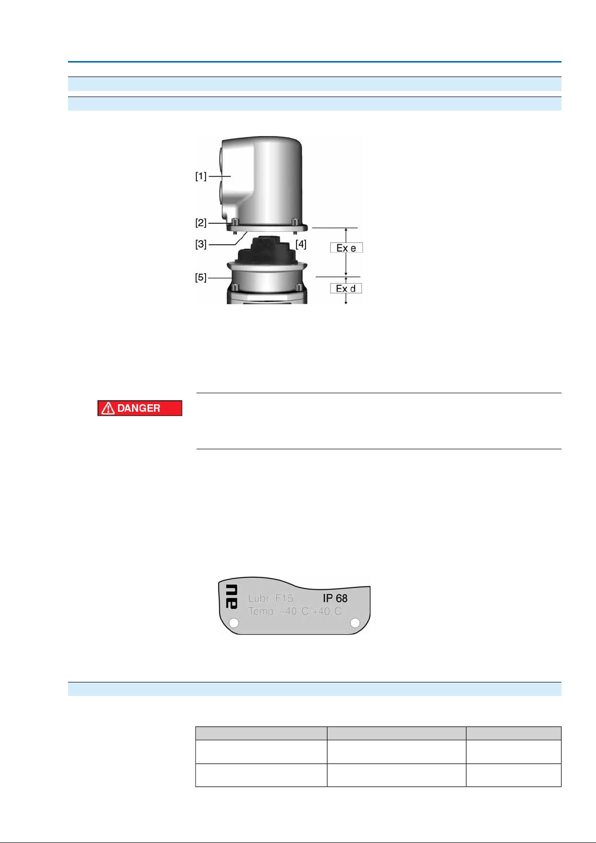
5.2. Connecting via Ex plug/socket connector with screw-type terminals (KP, KPH)
5.2.1. Terminal compartment: open
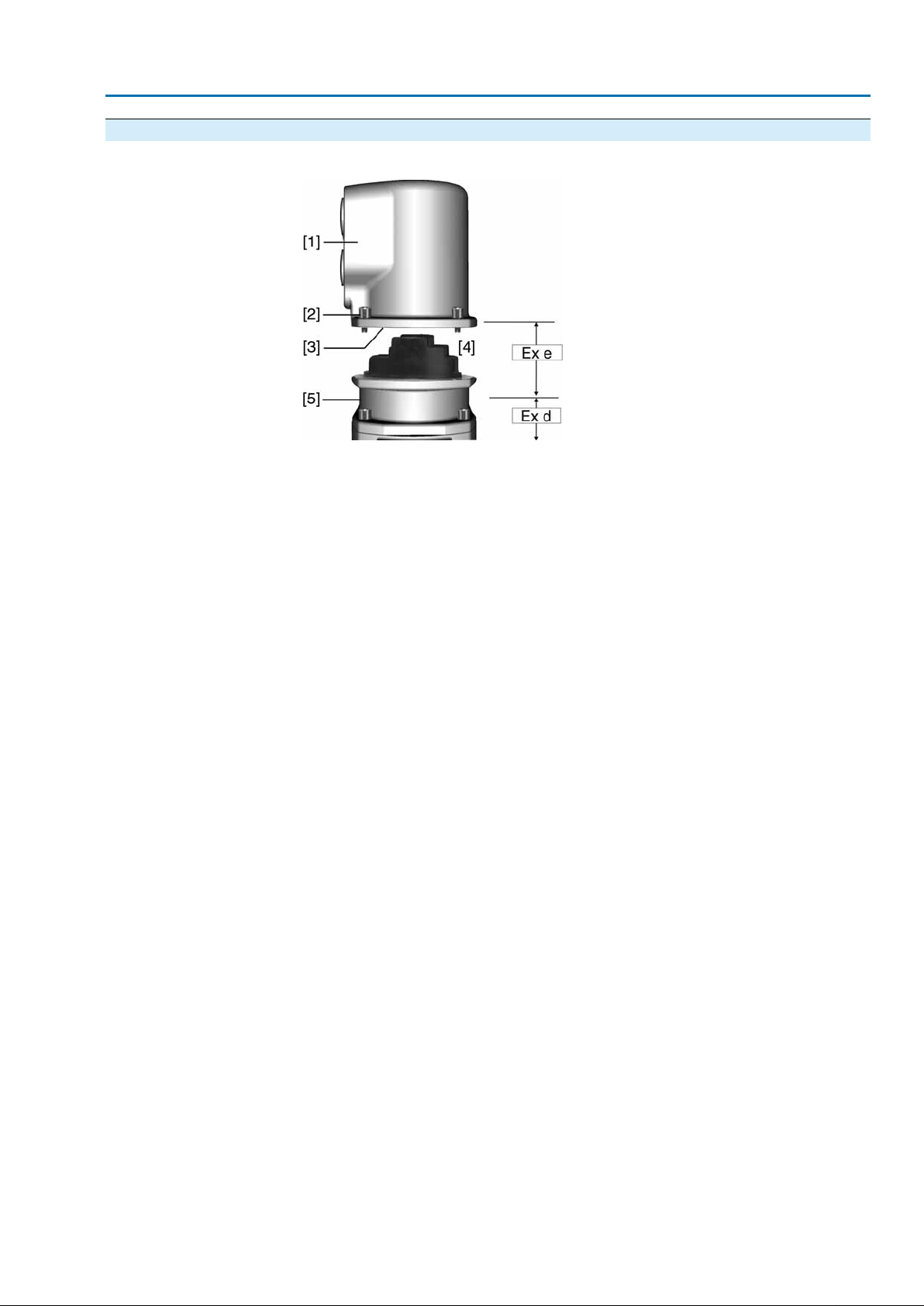
Figure 13: Ex plug/socket connector KPH
[1] Cover
[2] Screws for cover
[3] O-ring
[4] Terminal compartment
[5] Terminal board
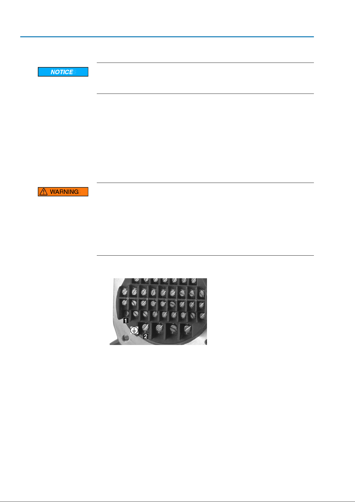
5.2.2. Cable connection
Hazardous voltage!
Risk of electric shock.
→
Disconnect device from the mains before opening.
1. Loosen screws [2] and remove cover [1].
Terminal compartment [4] is designed for explosion protection Ex e (increased
➥
safety).The flameproof compartment (type of protection Ex d) remains hereby
closed.
2. Insert cable glands with Ex e approv al and of size suitable f or connection cables.
The enclosure protection IP… stated on the name plate is only ensured if suit-
➥
able cable glands are used. Example: Name plate shows enclosure protection
IP68.
3. Seal cable entries which are not used with approved plugs suitable for the re-
quired protection type.
4. Insert the wires into the cable glands.
Table 8: Cross sections and tightening torques
Power terminals (U1, V1, W1)
PE connection
Control contacts (1 to 38)
(flexible or solid)
(flexible or solid)
Tightening torquesCross sectionsType
2 Nm(1.5)1) 2.5 – 6 mm²
1 Nm0.75 – 1.5 mm²
21
SAEx 07.2 – SAEx 16.2 / SAREx 07.2 – SAREx 16.2 Control unit - electromechanical
Electrical connection ACExC 01.2 Intrusive HART
with small clamp washers1)
Danger of corrosion: Damage due to condensation!
→
After mounting, commission the device immediately to ensure that heater minimises condensation.
1. Remove cable sheathing in a length of 120 – 140 mm.
2. Strip wires.
→
Controls max. 8 mm, motor 12 mm
3. For flexible cables: Use end sleeves according to DIN 46228.
4. Connect cables according to order-related wiring diagram.
Information: Two wires for each connection permitted.
→
When using motor cables with a cross section of 1.5 mm²: Use small clamp
washers for connection to terminals U1, V1, W1 and PE (the small clamp
washers are provided in the electrical connection cover).
In case of a fault: Hazardous voltage while protective earth conductor is NOT
connected!
Risk of electric shock.
→
Connect all protective earth conductors.
→
Connect PE connection to external protective earth conductor of connecting
cables.
→
Start running the device only after having connected the protective earth conductor.
5. Tighten protective earth firmly to PE connection
Figure 14: PE connection
[1] PE connection, control cable
[2] PE connection, motor cable
Information Some actuators are equipped with an additional motor heater.The motor heater
minimises condensation in the motor.
22
SAEx 07.2 – SAEx 16.2 / SAREx 07.2 – SAREx 16.2 Control unit - electromechanical
ACExC 01.2 Intrusive HART Electrical connection
5.2.3. Terminal compartment: close
Figure 15: Ex plug/socket connector KPH
[1] Cover
[2] Screws for cover
[3] O-ring
[4] Terminal compartment
[5] Terminal board
1. Clean sealing faces of cover [1] and housing.
2. Check whether O-ring [3] is in good condition, replace if damaged.
3. Apply a thin film of non-acidic grease (e.g. petroleum jelly) to the O-ring and
insert it correctly.
4. Fit cover [1] and fasten screws [2] evenly crosswise.
5. Fasten cable glands with the specified torque to ensure the required enclosure
protection.
23
SAEx 07.2 – SAEx 16.2 / SAREx 07.2 – SAREx 16.2 Control unit - electromechanical
Electrical connection ACExC 01.2 Intrusive HART
5.3. Connecting via Ex plug/socket connector with terminal blocks (KES)
5.3.1. Terminal compartment: open
Figure 16: Ex plug/socket connector: left KES, right KES flameproof
[1] Cover
[2] Screws for cover
[3] O-ring
[4] Terminal compartment: Type of protection Ex e
[5] Terminal compartment: Type of protection Ex d
[6] Frame
Hazardous voltage!
Risk of electric shock.
→
Disconnect device from the mains before opening.
1. Loosen screws [2] and remove cover [1].
Terminal compartments [4] and [5] are designed either in type of protection Ex
➥
e (increased safety) or in type of protection Ex d (flameproof enclosure). Hereby,
the flameproof interior compartment of the actuator (Ex d) remains closed.
2. Insert cable glands with Ex e approval and suitable for connection cables.
The enclosure protection IP… stated on the name plate is only ensured if suit-
➥
able cable glands are used. Example: Name plate shows enclosure protection
IP68.
3. Seal cable entries unused cable entries with approved plugs suitable for the
required protection type.
4. Remove cable sheathing and insert the wires into the cable glands.
5. Fasten cable glands with the specified torque to ensure required enclosure
protection.
24
SAEx 07.2 – SAEx 16.2 / SAREx 07.2 – SAREx 16.2 Control unit - electromechanical
ACExC 01.2 Intrusive HART Electrical connection
5.3.2. Cable connection
Table 9: Cross sections and tightening torques
Tightening torquesCross sectionsType
1.5 – 1.8 Nmmax. 10 mm² (flexible or solid)Power terminals (U, V, W)
3.0 – 4.0 Nmmax. 10 mm² (flexible or solid)PE connection
Control contacts (1 to 50)
max. 4 mm² (solid)
0.6 – 0.8 Nmmax.2.5 mm² (flexible), or
Danger of corrosion: Damage due to condensation!
→
After mounting, commission the device immediately to ensure that heater minimises condensation.
1. Strip wires.
2. For flexible cables: Use end sleeves according to DIN 46228.
3. Connect cables according to order-related wiring diagram.
In case of a fault: Hazardous voltage while protective earth conductor is NOT
connected!
Risk of electric shock.
→
Connect all protective earth conductors.
→
Connect PE connection to external protective earth conductor of connecting
cables.
→
Start running the device only after having connected the protective earth conductor.
4. Tighten protective earth firmly to PE connection
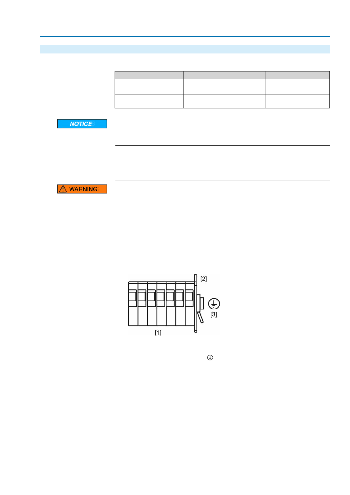
Figure 17: PE connection
[1] Terminal blocks
[2] Terminal housing
[3]
PE connection, symbol:
Information Some actuators are equipped with an additional motor heater.The motor heater
minimises condensation in the motor.
25

SAEx 07.2 – SAEx 16.2 / SAREx 07.2 – SAREx 16.2 Control unit - electromechanical
Electrical connection ACExC 01.2 Intrusive HART
5.3.3. Terminal compartment: close
Figure 18: Ex plug/socket connector: left KES, right KES flameproof
[1] Cover
[2] Screws for cover
[3] O-ring
[4] Terminal compartment: Type of protection Ex e
[5] Terminal compartment: Type of protection Ex d
[6] Frame
1. Clean sealing faces of cover [1] and housing.
2. Ex plug/socket connector designed as KES flameproof: Preserve joint surf aces
with an acid-free corrosion protection agent.
3. Check whether O-ring [3] is in good condition, replace if damaged.
4. Apply a thin film of non-acidic grease (e.g. petroleum jelly) to the O-ring and
insert it correctly.
Flameproof enclosure, danger of explosion!
Risk of death or serious injury.
→
Handle cover and housing parts with care.
→
Joint surfaces must not be damaged or soiled in any way.
→
Do not jam cover during fitting.
5. Fit cover [1] and fasten screws [2] evenly crosswise.
5.4. Accessories for electrical connection
5.4.1. Controls mounted to wall bracket
The wall bracket allows separate mounting of controls and actuator.
●
Application
If the actuator cannot be accessed.
●
If the actuator is subjected to high temperatures.
●
In case of heavy vibration of the valve.
26
SAEx 07.2 – SAEx 16.2 / SAREx 07.2 – SAREx 16.2 Control unit - electromechanical
ACExC 01.2 Intrusive HART Electrical connection
Design Figure 19: Design principle with wall bracket
[1] Wall bracket
[2] Connecting cables
[3] Electrical connection of wall bracket (XM)
[4] Electrical connection of actuator (XA)
[5] Electrical connection of controls (XK) – customer connector
Observe prior to connec-
tion
5.4.2. Parking frame Application
●
Permissible length of connecting cables: max. 100 m.
●
If the actuator is equipped with a position transmitter (RWG): Connecting cables
must be available as shielded version.
●
Versions with potentiometer in the actuator are not suitable.
●
We recommend: AUMA cable sets LSW8-KES or LSW9-KP.
●
If the AUMA cab le set is not used: Use suitab le flexib le and screened connecting
cables.
●
When using connecting cables, e.g. of the heater or switch, requiring direct
wiring from the actuator to the XK customer connector (XA-XM-XK, refer to
wiring diagram), these connecting cables must be subject to an insulation test
in compliance with EN 50178. Connecting cab les of position transmitters (RWG,
IWG, potentiometer) do not belong to this group.They may not be subject to
an insulation test.
Parking frame for safe storage of a disconnected plug.
For protection against touching the bare contacts and against environmental
influences.
Figure 20: Parking frame and Ex plug/socket connector with screw-type terminals
(KP/KPH)
27
SAEx 07.2 – SAEx 16.2 / SAREx 07.2 – SAREx 16.2 Control unit - electromechanical
Electrical connection ACExC 01.2 Intrusive HART
Figure 21: Parking frame and Ex plug/socket connector with terminal blocks (KES)
5.4.3. Protection cover
Protection cover for plug compartment when plug is removed.
The open terminal compartment can be closed using a protective cover (not
illustrated).
5.4.4. Earth connection, external
The housing is equipped with an external earth connection (U-bracket) to connect
the device to the equipotential earth bonding.
Figure 22: Earth connection
28
Loading...