


alféa excellia duo 11
Atlantic alféa excellia duo 11, alféa excellia duo 16, alféa excellia duo 14, WOYK160LCT, MH excellia duo Installation And Operating Manual
...
alféa excellia duo
Document n° 1572-4 ~ 12/12/2013
FR NL DE EN IT
Heat pump air/water
split 2 services
Outdoor unit Hydraulic unit
WOYG112LCT 023167
WOYG140LCT
WOYK112LCT
WOYK140LCT
WOYK160LCT
ES PT PL PT PT
Installation and
operating manual
intended for professionals
To be saved for
future consultation
atlantic-comfort.com
Subject to modications without notice.
Non contractual document.
Heat pump air/water split 2 services alféa excellia duo
" This device requires for its installation, the intervention of qualied personnel with a certicate of
capacity for handling refrigerants.
Contents
Description of the unit . . . . . . . . . . . . . . . . . . . . . . . . . . . . . . 4
Package . . . . . . . . . . . . . . . . . . . . . . . . 4
Denitions . . . . . . . . . . . . . . . . . . . . . . . 4
Specications . . . . . . . . . . . . . . . . . . . . . 5
Description. . . . . . . . . . . . . . . . . . . . . . . 9
Operating principle . . . . . . . . . . . . . . . . . 10
Installation . . . . . . . . . . . . . . . . . . . . . . . . . . . . . . . . . . . 12
Regulation installation and maintenance conditions . . 12
Unpacking and reservations . . . . . . . . . . . . . 12
Receipt . . . . . . . . . . . . . . . . . . . . 12
Handling . . . . . . . . . . . . . . . . . . . 12
Containment of refrigerant circuits . . . . . . 12
Accessories provided . . . . . . . . . . . . . 12
Installation position . . . . . . . . . . . . . . . . . 13
Installation of the outdoor unit . . . . . . . . . . . . 13
Installation precautions . . . . . . . . . . . . 13
Outdoor unit positioning . . . . . . . . . . . 14
Condensate drain hose . . . . . . . . . . . . 14
Installing the hydraulic unit . . . . . . . . . . . . . 15
Installation precautions . . . . . . . . . . . . 15
Refrigeration connections . . . . . . . . . . . . . . 16
Rules and precautions . . . . . . . . . . . . 16
Refrigeration connections. . . . . . . . . . . 17
Creating the arings . . . . . . . . . . . . . 17
Shaping the refrigeration pipes . . . . . . . . 17
Connecting the ared connections . . . . . . 17
Filling the installation with gas . . . . . . . . . . . . 19
Commissioning procedure . . . . . . . . . . 19
Sealing test . . . . . . . . . . . . . . . . . . 20
Additional charge . . . . . . . . . . . . . . . 21
Pump down operation (Refrigerant collecting
operation) outdoor unit . . . . . . . . . . . . 21
Hydraulic connecting . . . . . . . . . . . . . . . . 22
General . . . . . . . . . . . . . . . . . . . . 22
Connecting to the DHW circuit . . . . . . . . 23
Rinsing out the installation . . . . . . . . . . 24
Filling and purging the installation . . . . . . 24
Connecting the Fan convector
or dynamic radiator circuit . . . . . . . . . . 24
Thermal insulation . . . . . . . . . . . . . . . . . . 25
Heating circulation pump speed settings . . . . . . 26
Electrical connections . . . . . . . . . . . . . . . . 28
Characteristic of the electrical supply . . . . . 28
General remarks on electrical connections . . 28
Overview of all the electrical connections . . 29
Cable section and protection rating . . . . . . 29
Electrical connections
on the single phase outdoor unit side. . . . . 30
Electrical connections
on the 3- phase outdoor unit side . . . . . . . 31
Electrical connections
on the hydraulic unit side . . . . . . . . . . . 32
Outdoor sensor . . . . . . . . . . . . . . . . . . . 36
Room thermostat and/or room control unit . . . . . 36
Installing a room sensor . . . . . . . . . . . 36
Installing a room control unit . . . . . . . . . 36
Fan convectors or dynamic radiators area . . 36
Commissioning . . . . . . . . . . . . . . . . . . . 36
Conguring room thermostat . . . . . . . . . . . . 37
Conguring room control unit . . . . . . . . . . . . 37
- 2 -
Installation and operating manual "1572 - EN"
Heat pump air/water split 2 services alféa excellia duo
Regulation system . . . . . . . . . . . . . . . . . . . . . . . . . . . . . . . 38
User interface, Room control unit (option) and
Room thermostat (option) . . . . . . . . . . . . . . 38
Description of the display . . . . . . . . . . . . . . 40
Temperature control . . . . . . . . . . . . . . . . . 40
Set to . . . . . . . . . . . . . . . . . . . . . 40
Parametering the setting . . . . . . . . . . . . . . 42
General . . . . . . . . . . . . . . . . . . . . 42
Setting parameters . . . . . . . . . . . . . . 42
Recommended settings according
to the heat emitters installation . . . . . . . . 42
List of function lines
(settings, diagnosis, status) . . . . . . . . . . 43
Overall hydraulic layout . . . . . . . . . . . . . . . . . . . . . . . . . . . . 56
Electrical wiring diagrams . . . . . . . . . . . . . . . . . . . . . . . . . . . 58
Troubleshooting . . . . . . . . . . . . . . . . . . . . . . . . . . . . . . . . 62
Faults displayed on the hydraulic unit . . . . . . . . 62
Information display . . . . . . . . . . . . . . . . . 63
Faults displayed on the single phase outdoor unit . 64
Faults displayed on the 3-phase outdoor unit . . . . 65
Maintenance of the installation . . . . . . . . . . . . . . . . . . . . . . . . 66
Hydraulic checks . . . . . . . . . . . . . . . . . . 66
Maintenance of the DHW tank. . . . . . . . . . . . 66
Emptying the hot water tank . . . . . . . . . 66
Descaling . . . . . . . . . . . . . . . . . . . 66
Checking the outdoor unit . . . . . . . . . . . . . . 66
Electrical checks . . . . . . . . . . . . . . . . . . . 66
Maintenance . . . . . . . . . . . . . . . . . . . . . . . . . . . . . . . . . . 67
Emptying the hydraulic unit . . . . . . . . . . . . . 67
Distribution valve . . . . . . . . . . . . . . . . . . 67
ACI check . . . . . . . . . . . . . . . . . . . . . . 67
Instructions for the user . . . . . . . . . . . . . . . . . . . . . . . . . . . . 67
Quick-start procedure . . . . . . . . . . . . . . . . . . . . . . . . . . . . . 68
Start-up check-list . . . . . . . . . . . . . . . . . . 68
Before starting-up . . . . . . . . . . . . . . . 68
Starting-up . . . . . . . . . . . . . . . . . . 69
Installation and operating manual "1572 - EN" - 3 -
Settings sheet . . . . . . . . . . . . . . . . . . . . 70
Start-up data sheet . . . . . . . . . . . . . . . . . 71
Heat pump air/water split 2 services alféa excellia duo
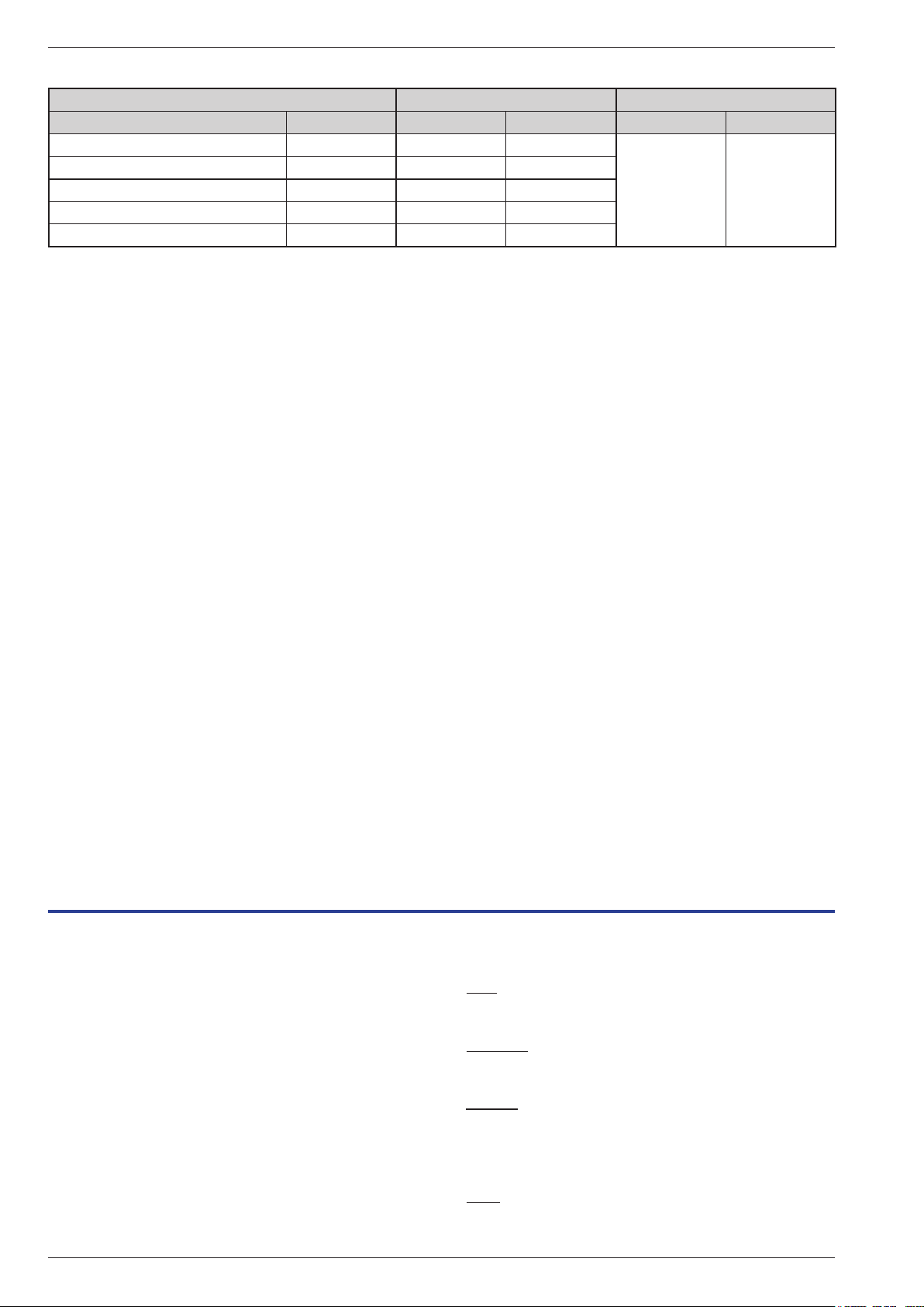
Packing list
Heat pump (HP) Outdoor unit Hydraulic unit
Model Code Model Code Model Code
alféa excellia duo 11 Single phase 522676 WOYG112LCT 700117
alféa excellia duo 14 Single phase 522677 WOYG140LCT 700142
alféa excellia duo 11 3-phase 522684 WOYK112LCT 700118
alféa excellia duo 14 3-phase 522685 WOYK140LCT 700143
alféa excellia duo 16 3-phase 522686 WOYK160LCT 700163
MH
excellia duo
023167
Optional equipment
• 2nd circuit kit (code 074011)
for connecting 2 heating circuits.
• Regulation extension kit (code 075311)
to manage a 2nd heating circuit, swimming pool etc...
• Boiler connection kit (code 073990)
for connecting a boiler to the heat pump.
• Single phase electrical back-ups kit (code 073985) or
3-phase electrical back-ups kit (réf. 073987).
• Room thermostat T37 (code 075308),
Room thermostat T55 (code 073951),
Room thermostat radio T58 (code 075313)
- for correcting the ambient temperature.
• Room control unit T75 (code 073954),
Room control unit radio T78 (code 074061)
for correcting the ambient temperature and
programming the heat pump.
• Anti-vibration blocks (code 523574).
• White PVC oor support (code 809532) or
Black rubber oor support (code 809536).
• Swimming pool kit (code 074726).
• Cooling kit (code 075312).
• High ow rate circulating pump kit (code 074077)
for the installation of 1 circuit oor heating
(with model > 13 kW).
Scope of application
This heat pump provides:
- Heating in winter,
- Control of two heating circuits*,
- Production of domestic hot water.
- Installation with boiler connection* as a
supplementary heating for the coldest days.
or
- the addition of electrical back-ups*, for extra heating
on the coldest days.
- Cooling in summer* (for oor heating-cooling system
or fan-convectors).
- Heating the swimming pool*.
* : These options require the use of additional kits
(see para "Optional equipment").
1 Description of the unit
1.1 Package
• 1 package: Outdoor unit.
• 1 package: Hydraulic unit and outdoor sensor.
- 4 -
1.2 Denitions
- Split: The heat pump consists of two elements
(an outdoor unit for outdoor and a hydraulic unit for
inside the dwelling).
- Air/water: The surrounding air is the energy source.
This energy is transmitted to the water in the heating
circuit by the heat pump.
- Inverter: the fan and compressor speeds are modulated
according to the heating requirements. This technology
enables you to save on energy and operate on a singlephase power supply, whatever the heat pump's output,
by avoiding heavy intensities on start-up.
- COP (coefcient of performance): this is the relationship
between the energy transmitted to the heating circuit
and electrical energy consumed.
Installation and operating manual "1572 - EN"
Heat pump air/water split 2 services alféa excellia duo
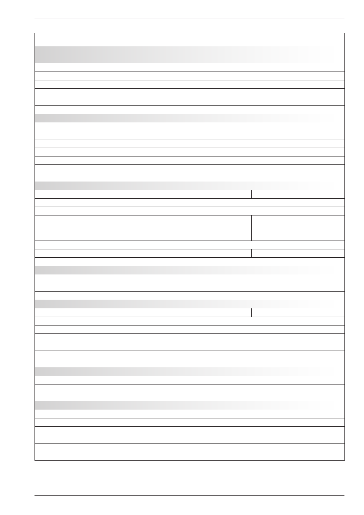
1.3 Specications
Designation model alfea excellia duo
11
Single phase
Nominal heating performances (outdoor temperature/ initial temperature)
Heat output
+7 °C / +35 °C - Floor heating system kW 10,80 13,50 10,80 13,00 15,17
-7 °C / +35 °C - Floor heating system kW 10,38 11,54 10,38 12,69 12,98
+7 °C / +45 °C - Low temperature radiator kW 9,05 11,32 9,90 12,34 12,75
-7 °C / +45 °C - Low temperature radiator kW 9,16 11,45 9,98 10,74 12,95
+7 °C / +55 °C - Radiator kW 7,59 9,48 9,29 10,81 12,71
-7 °C / +55 °C - Radiator kW 7,57 9,20 9,27 10,02 11,99
Power absorbed
+7 °C / +35 °C - Floor heating system kW 2,54 3,23 2,51 3,11 3,70
-7 °C / +35 °C - Floor heating system kW 4,32 5,13 4,28 5,13 5,40
+7 °C / +45 °C - Low temperature radiator kW 2,82 3,69 2,99 3,81 3,97
-7 °C / +45 °C - Low temperature radiator kW 4,58 5,92 4,63 5,14 6,37
+7 °C / +55 °C - Radiator kW 3,07 3,95 3,52 4,49 5,04
-7 °C / +55 °C - Radiator kW 4,57 5,08 5,09 5,64 6,89
Coefcient of performance (COP) (+7 °C / + 35 °C) 4,25 4,18 4,30 4,18 4,10
Electrical characteristics
Supply voltage (50 HZ) V 230 400
Maximum current for appliance A 22 25 8,5 9,5 10,5
Nominal current A 11,4 14,2 3,7 4,8 5,5
Maximum current of the Heating electrical back-ups A 13,05 / 26,1 3x13
Power of the Heating electrical back-ups (option) kW ajustable 3 or 6 kW (Single phase) 9 kW (3-phase)
Real power absorbed by the fan W 2x100 2x10⁴
Real power absorbed by the circulation pump W 37,5
Maximum power absorption by the outdoor unit W 5060 5750 5865 6555 7245
Electrical back-up power DHW W 1500
Hydraulic circuit
Maximum operating pressure Heating bar 3
Maximum operating pressure Domestic hot water tank bar 10
Hydraulic system ow rate 4°C<Δt<8°C (nominal conditions) l/h 1170 / 2340 1460 / 2920 1170 / 2340 1460 / 2920 1650 / 3290
Various
Weight of outdoor unit kg 92 99
Weight of hydraulic unit (empty / full of water) kg 146 / 350
Water capacity of the hydraulic unit / of the domestic tank l 24 / 190
Noise level at 1 m 1 (hydraulic unit) dB 39
Sound power level according to EN 12102 2 (hydraulic unit) dB 46
Noise level at 1 m 1 (outdoor unit) dB 42 43 39 41 42
Sound power level according to EN 12102 2 (outdoor unit) dB 69 70 66 68 69
Heating system operating limits
Outdoor temperature mini / maxi °C -25 / +35
Initial max. heating water temperature Floor heating system °C 45
Initial max. heating water temperature Low temperature radiator °C 60
Refrigeration circuit
Diameter of "Gas" pipes inches 5/8
Diameter of "Liquid" pipes inches 3/8
Factory charge of refrigerant R410A 3 g 2500
Maximum operating pressure bar 41,5
Minimum / Maximum length of pipes
4
m 5 / 15
Maximum length of pipes 5 / Maximum level difference m 20 / 20
1
Sound pressure level in (x)m of the device, 1,5m of the ground,
the open eld.
2
The sound power level is a laboratory measure of the emitted
sound power but contrary to the noise level, it doesn't correspond to
the measure of the felt.
3
Refrigerant R410A (as per the standard EN 378.1).
4
Factory charge of refrigerant R410A.
5
Taking into account the possible additional load of refrigeration uid
R410A (see "Additional charge", page 21)
14
Single phase
11
3-phase
14
3-phase
16
3-phase
Installation and operating manual "1572 - EN" - 5 -

Heat pump air/water split 2 services alféa excellia duo
" Outside unit,
Model excellia duo
11 & 14 Single phase
650
Air
370
" Outside unit,
Model excellia duo
11, 14 & 16 3-phase
31 77900330 12
Air
Air
400
Side view
Overflow hole (Ø 20) 4Ø10)Holes
3/8”
5/8”
196
99
147
170
Sight of lower part
9
Front view
Top view
650
Air
1290
21
31 12330
Air
Air
400
Side view
370
Overow hole (ø 20)
Sight of lower part
4 Holes (ø 10)
900
1290
21
9
Front view
- 6 -
Top view
gure 1 - Dimensions in mm
Installation and operating manual "1572 - EN"
Heat pump air/water split 2 services alféa excellia duo
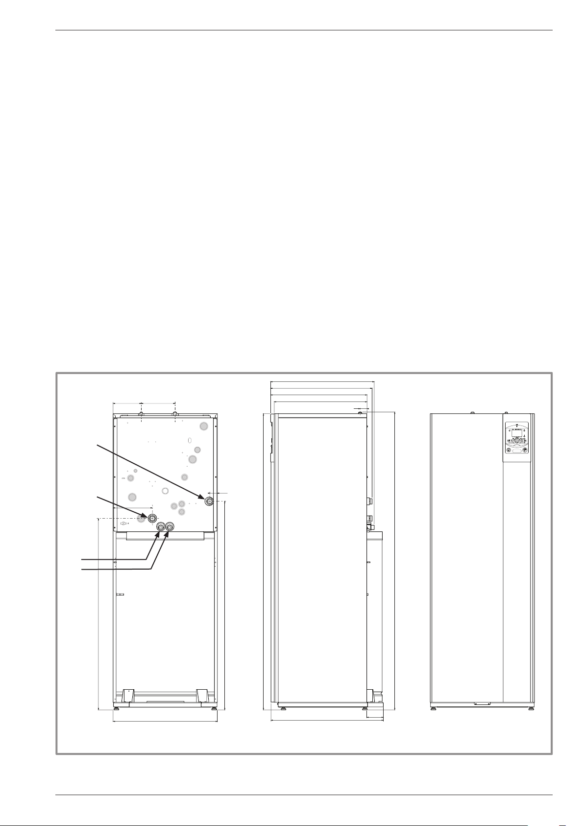
" Hydraulic unit
Heating return
Heating ow
DHW
DCW
1189
175 210
244
47
1296
1840
644
630
599
576
43
1850
648
Back view
698
Side view Front view
103
Blockage in the hydraulic unit, see gure 13, page 15.
gure 2 - Dimensions in mm
Installation and operating manual "1572 - EN" - 7 -
-50
-25025 50 75
°C
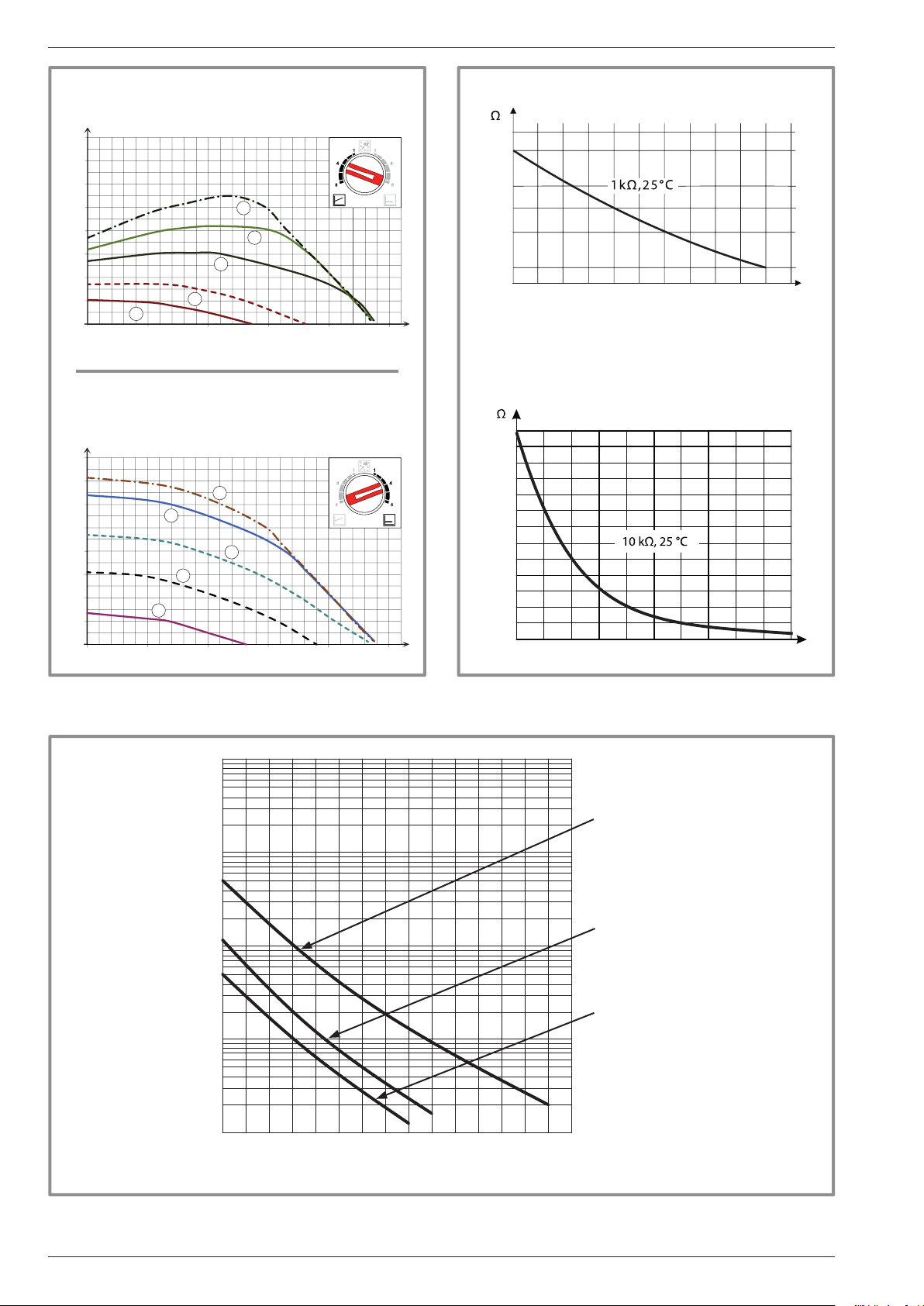
Heat pump air/water split 2 services alféa excellia duo
Variable pressure
mCE
8
7
6
5
4
3
2
1
0
0 0,5 1 1,5 2
1
55
3
1
1 mbar=10 mmCE=100 Pa
88
77
Constante pressure
mCE
8
7
6
5
4
3
2
1
0
0 0,5 1 1,5 2
77
1
88
55
3
1
1 mbar=10 mmCE=100 Pa
Outdoor sensor QAC34
43907
10000
2490
1000
338
3
3
/h
1,5 20,50
m
m/h
Heat pump return sensor
Heat pump ow sensor
32500
30000
27500
25000
22500
20000
17500
15000
12500
10000
7500
5000
2500
3
3
/h
1,5 20,50
m
m/h
0
0102030405060708090 100
°C
gure 3 - Hydraulic pressures and ow rates available
10000
1000
Ohmic value (kΩ)
100
10
1
-20 -10 0 10 20 30 40 50 60 70 80 90 100 110 120 130
gure 4 - Ohmic values of the sensors
(Hydraulic module)
- Compressor
- Discharge
- Condensation
- Outside
- Evaporator outlet
- Evaporator center
- Compressor casing
Temperature °C
- 8 -
gure 5 - Ohmic values of the sensors (outside unit)
Installation and operating manual "1572 - EN"
Heat pump air/water split 2 services alféa excellia duo
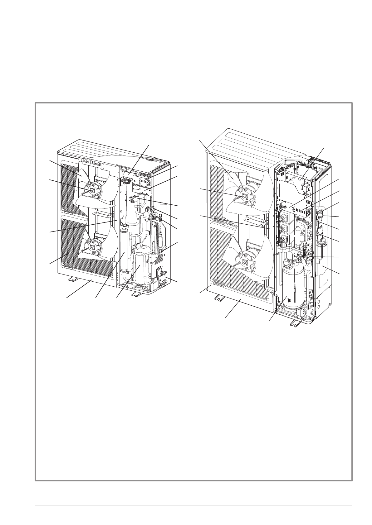
1.4 Description
" Model excellia duo 11 & 14
single phase
1
2
13
8
12
6
10
" Model excellia duo 11, 14 & 16
3-phase
WO*K1**LCT
5
4
7
15
14
9
13
1
3
4
2
5
14
15
9
7
3
11
6
11
8
12
Legend :
1 - Low-noise, high-output fan.
2 - Electric variable speed "inverter" motor.
3 - "Inverter" control module.
4 - Vacuum start (pump down) and control light.
5 - Connection terminal blocks (power and interconnection).
6 - Refrigerant accumulator bottle.
7 - Cycle reversing valve.
8 - Anti-corrosion treated bodywork.
9 - Electronic expansion valve.
10 - Noise and temperature insulated "inverter" compressor.
11 - Refrigeration connection valves (ared connectors) with protective caps.
12 - Holding tank with condensate drain hole.
13 - High-performance exchange surface evaporator ;
anti-corrosion treated hydrophilic aluminium ns and grooved copper tubes.
14 - Solenoid valve for liquid injection.
15 - Electric expansion valve for liquid injection.
gure 6 - Outdoor unit components
10
Installation and operating manual "1572 - EN" - 9 -
Heat pump air/water split 2 services alféa excellia duo
6 7
13
15
18
2
12
3
1
10
9
21
23
14
4
5
22
9
11
17
16
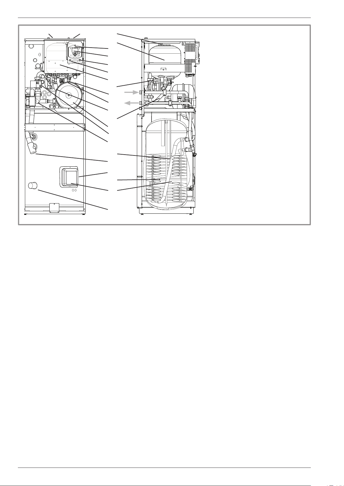
Legend :
1 - Electric box.
2 - Regulator / User interface.
3 - Start/stop switch.
4 - Hydraulic pumping unit.
5 - Distribution valve.
8
6 - Gas refrigeration connection.
7 - Liquid refrigeration connection.
8 - Condensation sensor.
9 - Drain valve.
10 - Safety valve.
11 - Safety thermostat.
12 - Manometer.
13 - Manual drainer.
14 - Expansion vessel.
15 - Condenser.
16 - Electrical back-ups DHW.
17 - ACI.
18 - ACI card.
Sensors :
21 - Water ow sensor.
22 - DHW sensor.
23 - Water return sensor.
9
gure 7 - Hydraulic unit components
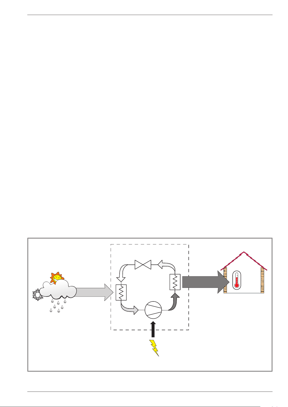
1.5 Operating principle
The heat pump transmits the energy contained in the
surrounding air into the dwelling to be heated.
The heat pump consists of four main elements, in which
a refrigerant uid (R410A) circulates.
- In the evaporator (ref. 13, gure 6, page 9) :
The energy is taken from the surrounding air and is
transmitted to the refrigerant. Because it has a low
boiling point, it changes from the liquid state to the
vapour state, even in cold weather (down to -15 °C
outdoor temperature).
- In the compressor (ref. 10, gure 6, page 9) :
The vaporised refrigerant brought to high pressure
and takes on more calories.
- In the condenser (ref. 15, gure 7) :
The energy in the refrigerant is transmitted to the
heating circuit. The refrigerant returns to liquid state.
- In the expansion valve (ref. 9, gure 6, page 9) :
The lique ed refrigerant is brought back to low pressure
and returns to its initial temperature and pressure.
The heat pump is equipped with a controller, which
controls the room temperature based on the outdoor
temperature measurement and governed by the
temperature control. The room thermostat (option)
provides a corrective action for the temperature control.
The hydraulic unit can be optionally tted with an
electrical back-up system or boiler connection which
starts up in order to provide addtional heating during the
coldest periods.
• Regulation functions
- The heating circuit's initial temperature is controlled by
the temperature control.
- The power of the outdoor unit is modulated according
to ow heating temperature via the "inverter"
compressor.
- Control of the electrical back-up heating (option).
- The daily timer program enables you to de ne
the periods for comfortable or reduced ambient
temperature.
- Summer/winter mode switchover is automatic.
- Control of the supplementary boiler* (option).
- The room thermostat (option)*: provides a corrective
action for the temperature control.
- Control of a second heating circuit*.
- Domestic hot water: Heating time programme, control
of the operation of the DHW circulation pump.
- Managing the cooling*.
- Control of swimming pool heating*.
* If the heat pump is equipped with optional equipment and the
associated kits.
• Protection functions
- Anti-legionella cycle for domestic hot water.
- Anti-corrosion protection with titanium anode (ACI).
- Frost protection: Frost protection cuts in if the low-
temperature point of the heating circuit falls below 5 °C
(provided that the heat pump's electrical power supply
is not interrupted).
- 10 -
Installation and operating manual "1572 - EN"
Heat pump air/water split 2 services alféa excellia duo
• Domestic hot water (DHW) operating principle
Two domestic hot water (DHW) temperatures can be
parametered: nominal temperature (line 1610 to 55 °C)
and reduced temperature (line 1612 to 40 °C).
The default heat pump program (line 560, 561 and 562)
is set for nominal temperature from 0:00 to 5:00 and
from 14:30 to 17:00 and for reduced temperature for the
rest of the day. This optimizes electrical consumption
while ensuring comfortable availability of hot water.
Setting for reduced temperature can be useful to prevent
the DHW from switching on too often and for too long
during the day.
The production of domestic hot water (DHW) is triggered
when the temperature in the tank falls 7°C (setting from
line 5024) below the set temperature.
The heat pump produces the domestic hot water, which
is then additively heated, if required, by electrical backup heating inside the tank. To ensure a DHW setting
over 45°C, the electrical back-up heating or the boiler
must be left on.
Depending on how the parameter (1620) is set, nominal
temperature can be reached 24h/day or only at night or
depending on the heat pump programme.
If the contract concluded with the energy provider
includes a subscription to day/night tariff, the electrical
backup is subordinate to the supplier’s power tariff and
the comfort temperature may only be reached at night.
If no particular contract is concluded, the comfort
temperature can be reached at any time, including
during the day
The production of DHW takes priority over heating;
nevertheless the production of DHW is controlled by
cycles that control the times assigned to the heating
and the production of DHW in the event of simultaneous
demand.
A function to switch from "reduced" to "nominal"
is provided on the front of the user interface.
(see ref. 1, gure 42, page 38).
Anti-legionella cycles can be programmed.
• Fan convectors with integrated control system
Do not use a room sensor in the area.
Energy from the air
PAC
HP
Dt
Cn
Ev
Electrical
energy
consumed
gure 8 - Heat pump operating principle
Cp
1kW
Heat produced
COP 4
4kW
20 °C
HP - Heat pump
Ev - Evaporator
Cp - Compressor
Cn - Condenser
Dt - Expansion valve
Installation and operating manual "1572 - EN" - 11 -

Heat pump air/water split 2 services alféa excellia duo
2 Installation
2.1 Regulation installation
and maintenance conditions
The appliance must be installed and the maintained
by an approved professional in accordance with the
prevailing regulations and code of practice, in particular:
- The legislation on the handling of refrigerants.
- Heating installation with oor heating system.
- Low voltage electrical installations - Rules.
2.2 Unpacking and reservations
2.2.1 Receipt
Carefully check, in the carrier's presence, the general
appearance of the appliances and check that the
outdoor unit is not laid on its side or back.
In the case of any dispute, state any appropriate
reservations to the carrier in writing within 48 hours and
send a copy of this letter to the After-Sales service.
2.2.2 Handling
The outdoor unit should not be laid on its side or back
during transport.
If not kept upright during transport, the appliance could
be damaged through displacement of the refrigerant
and deformation of the compressor suspension.
Any damage caused by transportation of the unit lying
down is not covered by the warranty.
If necessary the outdoor unit may be tilted only during
manual handling (to go through a door or use a staircase).
This operation must be conducted very carefully and
the appliance must be immediately restored to upright
position.
2.2.3 Containment of refrigerant circuits
All refrigerant circuits fear contamination from dust and
moisture. If such pollutants introduced into refrigeration
circuit, they can contribute to degrade the reliability of
the heat pump.
" It’s necessary to ensure correct containment
connections and refrigerant circuits (hydraulic
unit, outdoor unit).
" In case of subsequent failure and expertise, the
nding of the presence of moisture or foreign
objects into the compressor oil would lead to
systematic exclusion of warranty.
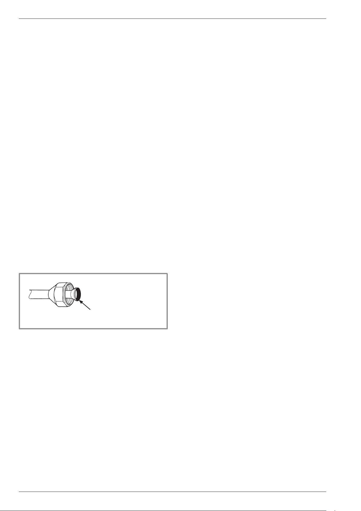
- Check upon receipt that the ttings and the refrigeration
circuit caps mounted on hydraulic unit and outdoor unit
are properly seated and locked (impossible to loosen
bare hands). If this’s not the case, tighten them using
an against wrench.
- Check also that the refrigerant connections are
sealed (plastic caps or tubes crushed at the ends
and soldered). If the caps must be removed during
installation (tubes cut by example), put back them as
soon as possible.
2.2.4 Accessories provided
Accessories provided with the outdoor unit (gure 9).
Accessories provided with the hydraulic unit (gure 10).
10
5
1
7
3
1
1 Elbow
Plug (x 2)(Depending
2
on the model)
3 Hex / Allen key To open the valves
gure 9 - Accessories provided with the outdoor unit gure 10 - Accessories provided with the hydraulic unit
2
3
For draining away the
condensates
4
1 Dielectric ttings
2 DHW pipes
3 Gaskets
4 Outdoor sensor
7 Insulation right
8 Insulation conical
9 Insulation tape
10 Insulation tube
2
3
8
for connection to the DHW
circuit
to monitor the outside
temp
to isolate the connections
and tubes
9
64
- 12 -
Installation and operating manual "1572 - EN"
Heat pump air/water split 2 services alféa excellia duo
2.3 Installation position
The choice of the position for installation is particularly
important insofar as any later movement is a delicate
operation requiring the intervention of a qualied person.
Choose the site of the outdoor unit and the hydraulic
unit after discussion with the customer.
Observe the maximum and minimum distances between
the hydraulic unit and the outdoor unit (gure 18, page 18),
the guarantee of the performances and the system's
service life depend on this.
2.4 Installation of the outdoor unit
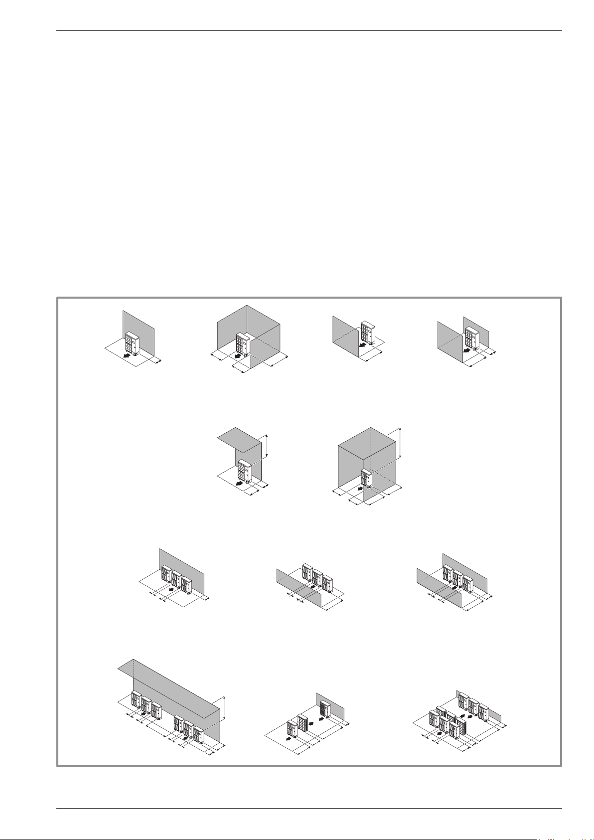
2.4.1 Installation precautions
The outdoor unit must only be installed outdoor
(outdoors). If a shelter is required, it must have
broad openings on the 4 walls and observe the
installation clearances (gure 11).
• Choose a site that is preferably sunny and sheltered
from strong cold predominant winds (mistral,
tramontana, etc…).
• The unit must be easily accessible for future installation
and maintenance work (gure 11).
• Ensure that it is possible to make the connections to
the hydraulic unit easily.
• The outdoor unit is able to withstand bad weather but
avoid installing in a position where it is likely to be
exposed to signicant dirt or owing water (under a
defective gutter for example).
• Water may drain away from the outdoor unit when it
is operating. Do not install the appliance on a paved
terrace; choose a well-drained place (e.g. gravel
or sand). If the installation is in an area where the
temperature can be lower than 0°C for a long period,
check that the presence of ice does not present any
danger. A drainage pipe can also be connected to the
outdoor unit (gure 12).
250
Minimum
250
or more
150
200
300
200
1000
300
Max. 500
250
250
or more
Minimum
300
250
1500
or more
Minimum
250
1000
or more
Minimum
Max. 500
500
1500
250
250
or more
Minimum
1000
or more
Minimum
500
1500
or more
Minimum
150
500
Max.300
1500
1000
600
150
2000
or more
Minimum
250
250
or more
Minimum
1500
600
3000
or more
Minimum
600
250
Minimum
250
or more
1500
250
Minimum
250
or more
gure 11 - Minimum installation clearances around outside unit (all models)
Installation and operating manual "1572 - EN" - 13 -
Heat pump air/water split 2 services alféa excellia duo
• Nothing should obstruct the air circulation through the
evaporator and from the fan (gure 11).
• Keep the outdoor unit away from heat sources and
inammable products.
• Make sure the appliance not disturb the surrounding
area or users (noise level, draught generated, low
temperature of the air being blown out, with the risk of
freezing plants in its path).
• The surface on which the appliance is installed must:
- be permeable (soil, gravel, etc),
- support its weight easily,
- provide a solid xing and
- not transmit any vibration to the dwelling.
(Anti-vibratory blocks are available as an option).
• The wall bracket can not be used in conditions likely to
transmit vibrations, ground position is preferred.
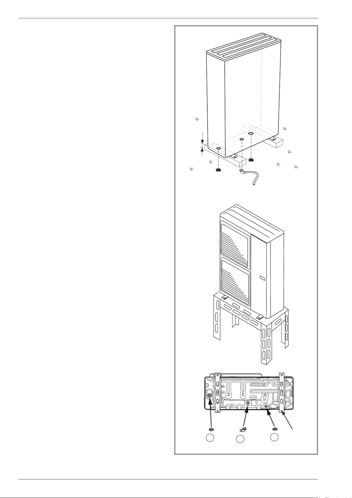
2.4.2 Outdoor unit positioning
The outdoor unit must be raised at least 50 mm above
ground level. In areas prone to snow, this height should
be increased but should not exceed 1,5 m (gure 12).
- Fasten the outdoor unit by means of screws and
rubber tightening or toothed lock washers to avoid
their coming loose.
" Warning
In the area with heavy snowfall, if the intake and outlet
of outdoor unit is blocked with snow, it might become
difcult to get warm and it is likely to cause of the
breakdown.
Please construct a canopy and a pedestral or place the
unit on high stand (local congured).
- Set the unit on a strong stand, such as one made of
concrete blocks to minimize shock and vibration.
- Do not set the unit directly on the ground because it will
cause trouble.
* In regions subject to frequent snow,
(H) must be greater than the average snow layer
2.4.3 Condensate drain hose
(see gure 12).
If the use of a discharge pipe is imperative:
- Use the elbow provided (C) to connect a 16mm-
diameter hose for draining away the condensate.
- Use the stopper or stoppers provided (B) to block the
opening of the condensate tank.
Allow for the condensate to ow away under the force of
gravity (waste water, rain water, gravel bed).
" If the installation is made in an area where
the temperature can be lower than 0°C for
a long period, provide the drain pipe with a
trace resistance to avoid it icing up. The trace
resistance must heat not only the pipe but
also the bottom of the appliance's condensate
collection tank.
4 holes
B
gure 12 - Positioning of the outside unit,
draining away the condensate
C
B
(ø 12 mm)
- 14 -
Installation and operating manual "1572 - EN"
Heat pump air/water split 2 services alféa excellia duo
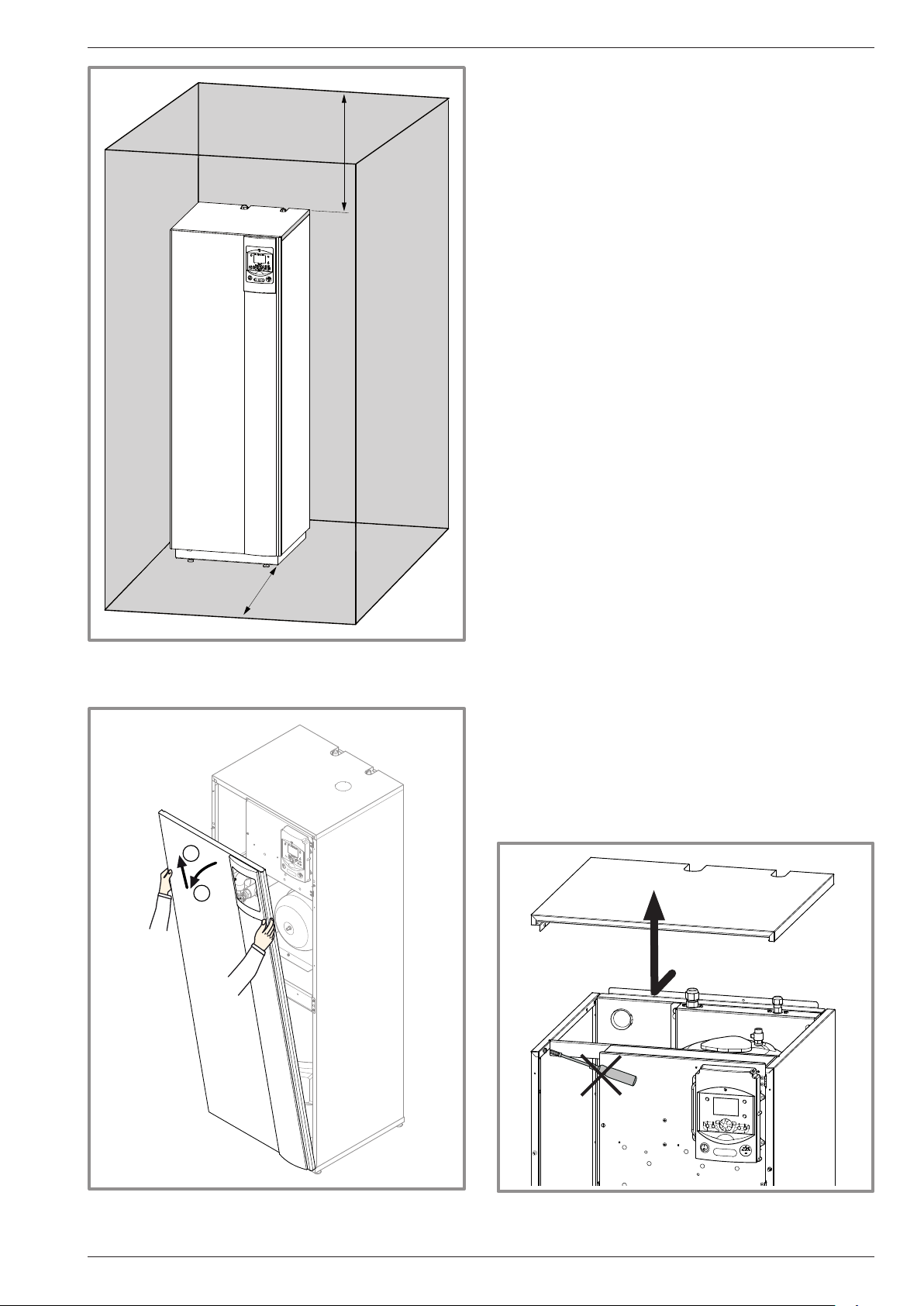
2.5 Installing the hydraulic unit
2.5.1 Installation precautions
1800 mm
300 mm
125 mm
• The room in which the appliance operates must
comply with the prevailing regulations.
• To facilitate maintenance and to allow access to the
various components, we recommend that you provide
sufcient space all around the hydraulic unit (gure 13).
• Be careful not to bring inammable gas near to the
heat pump during its installation, in particular when
it requires brazing. The appliances are not reproof
and should therefore not be installed in a potentially
explosive atmosphere.
- To avoid condensation inside the condenser, remove
the refrigerant circuit caps only when building the
refrigerant connections.
- If the refrigerant connection only occurs at the end of
the installation, be sure that the refrigerant circuit caps*
remain in place and tight throughout the installation
duration.
* (hydraulic unit side and outdoor unit side)
- After every intervention on the refrigeration circuit and
before nal connection, take care to replace the plugs
in order to avoid any pollution from the refrigeration
circuit (The sealing with tape is prohibited).
1000 mm
gure 13 - Minimum installation clearances
around the hydraulic module
and distances to the combustible partitions
2
1
Front view
gure 14 - Open the front cover gure 15 - Removing the cover
Installation and operating manual "1572 - EN" - 15 -
Heat pump air/water split 2 services alféa excellia duo
2.6 Refrigeration connections
" This appliance uses refrigerant R410A.
Comply with the legislation for handling refrigerants.
2.6.1 Rules and precautions
• After every intervention on the refrigeration circuit and
before nal connection, take care to replace the plugs in
order to avoid any pollution from the refrigeration circuit.
• Minimum necessary tools
- Set of manometers (Manifold) with hoses exclusively
reserved for HFCs (Hydrouorocarbons).
- Vacuum gauge whith isolation valves.
- Vacuum pump specially for HFCs (use of a traditional
vacuum pump is authorized if, and only if, it is tted
with a non-return valve on the suction side).
- Flaring tool.
- Pipe-cutter.
- Deburring tool.
- Wrenches.
- Refrigerant gas leak detector certied (sensitivity 5g/year).
" Provision on using tools that have been in
contact with HCFCs (R22 for example) or CFCs.
" The manufacturer declines any liability with
regard to the guarantee if the above instructions
are not observed.
• Flared connections
" Lubrication with mineral oil (for R12, R22)
is forbidden.
- Only lubricate with polyolester refrigeration oil (POE).
If POE is not available, t without lubrication.
• Brazing on the refrigeration circuit (if necessary)
- Silver brazing (40% minimum recommended).
- Brazing only under dry nitrogen internal ux.
• To eliminate any lings in the pipes, use dry nitrogen
to avoid introducing any humidity that may adversely
affect the appliances operation. In general, take every
precaution to avoid humidity penetrating into the
appliance.
• Proceed to insulate the "Gas" and "Liquid" pipes to
avoid any condensation. Use pipe insulators resistant
to temperatures over 90°C. In addition if the humidity
level in areas where the refrigeration pipes are
installed is expected to exceed 70%, protect the pipes
with pipe insulators. Use an insulating material thicker
than 15mm if the humidity level is 70~80%, and an
insulating material thicker than 20mm if the humidity
exceeds 80%. If the recommended thicknesses are
not observed under the conditions described above,
condensation will form on the surface of the insulation
material. Lastly, take care to use pipe insulators
whose thermal conductivity is 0.045 W/mK or less
when the temperature is 20°C. The insulation must be
impermeable to resist the passage of steam during the
defrosting cycles (breglass wool is prohibited).
Coat the ared surface
with POE refrigeration oil.
Do not use mineral oil.
- 16 -
Installation and operating manual "1572 - EN"
Heat pump air/water split 2 services alféa excellia duo
2.6.2 Refrigeration connections
The outdoor unit must be connected to the hydraulic unit
only with copper pipes and connections (refrigeration
quality), insulated separately.
Comply with the pipe diameters and the permitted pipe
lengths (gure 18).
The minimum length of the refrigeration connections
is 5 m for correct operation.
The appliance will be excluded from guarantee if it is
used with refrigeration connections less than 5 m long.
If the refrigeration connections are exposed to
weathering or UV- and the insulation is not strong, it is
necessary to provide protection.
Manipulate the pipes and take them through walls with
protective plugs in place.
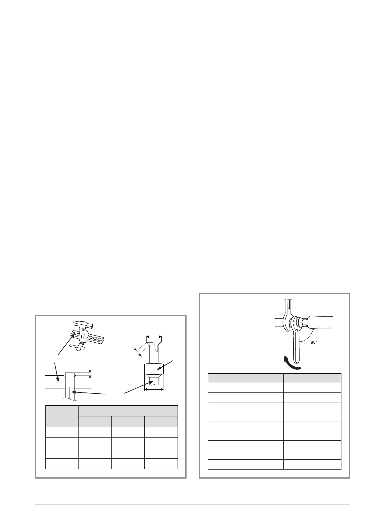
2.6.3 Creating the arings
- Cut the pipe to an appropriate length with a pipe-cutter
without deforming it.
- Carefully deburr it, holding the pipe towards the bottom
to avoid introducing lings into the pipe.
- Remove the ared connection nut situated on the
valve to be connected and slip the pipe into the nut.
- Proceed to are, letting the pipe overow the aring
tool.
- After aring, check the condition of the working
radius (L). This must not show any scratch or trace of
any fracturing. Also check the dimension (B).
2.6.4 Shaping the refrigeration pipes
The refrigeration pipes must be shaped only on a
bending machine or with a bending spring in order to
avoid any risk of crushing or breaking them.
" Warning !
• Remove the insulation material locally to bend the
pipes.
• Do not bend the copper to any angle over 90°.
• Never bend pipes more than 3 times in the same
position otherwise traces of fracturing may appear
(from strain-hardening the metal).
2.6.5 Connecting the ared connections
" Connections must be made the day of the lling
the installation with gas (see para. "Filling the
installation with gas", page 19).
" Take particular care positioning the tube opposite
its connector so as not to risk damaging the
threads. A carefully aligned connector can be tted
easily by hand without much force being required.
" The refrigeration circuit is very sensitive to dust
and humidity: check that the area around the
connection is clean and dry before removing the
plugs protecting the refrigeration connectors.
- Remove the plugs from the pipes and the refrigeration
connections.
- Present the pipe to the ared connector and screw the
nut by hand while holding the connector with a wrench
until contact.
- Comply with the indicated tightening torques.
B
Flaring tool
Hose
dimensions in mm
ø Hose
L B 0/
6,35 (1/4") 1,8 to 2 9,1 17
9,52 (3/8") 2,5 to 2,7 13,2 22
12,7 (1/2") 2,6 to 2,9 16,6 26
15,88 (5/8") 2,9 to 3,1 19,7 29
gure 16 - Flaring for are connections
L
C
-0,4
Holding wrench
Flare
nut
C
Torque wrench
Designation Tightening torque
Flare nut 6,35 mm (1/4") 14 to 18 Nm
Flare nut 9,52 mm (3/8") 33 to 42 Nm
Flare nut 12,7 mm (1/2") 50 to 62 Nm
Flare nut 15,88 mm (5/8") 63 to 77 Nm
Plug (A) 3/8", 1/4" 20 to 25 Nm
Plug (A) 1/2" 25 to 30 Nm
Plug (A) 5/8" 30 to 35 Nm
Plug (B) 3/8", 5/8" 10 to 12 Nm
Plug (B) 1/2", 1/4" 12,5 to 16 Nm
gure 17 - Tightening torque
Installation and operating manual "1572 - EN" - 17 -
DL
Heat pump air/water split 2 services alféa excellia duo
HP model alféa excellia duo Single phase & 3-phase
gas uid
Outdoor unit connections 5/8" 3/8"
Diameter (D1) 5/8" (D2) 3/8"
Refrigeration
connections
Minimum length (L) 5
Maximum length* (L) 15
Maximum length** (L) 20
Maxi level difference**(D) 20
Hydraulic unit connections 5/8" 3/8"
* : without additional charge of R410A.
** : Taking into account the possible additional load of refrigerant R410A (see para. "Additional charge", page 21).
HP
HP
Outdoor unit
Liquid
valve
Flare
Gas
valve
Flare
nut
nut
Flare nut
"Liquid" refrigeration connection
Diameter D2
Hydraulic unit
“Gas” refrigeration connection
Diameter D1
Flare nut
- 18 -
gure 18 - Connecting the ared connections (Pipe diameters and permissible lengths)
Installation and operating manual "1572 - EN"
Jeu de manomètres
Heat pump air/water split 2 services alféa excellia duo
2.7 Filling the installation with gas
" This operation is reserved for installers familiar
with the legislation for handling refrigerants.
" Creating a vacuum with a vacuum pump is
essential (see ANNEX 1).
" Never use equipment used beforehand with any
refrigerant other than a HFC.
" Remove the refrigerant circuit caps only when
building the refrigerant connections.
" Unfavorables conditions :
- If the outdoor temperature is between +5 and
+10 °C, it’s obliged to have a vacuum gauge for
validate the pump down operation and use method
3 empty. (see ANNEX 2).
- If the outdoor temperature is below +5 °C,
it’s strongly not recommended to do the lling the
installation with gas.
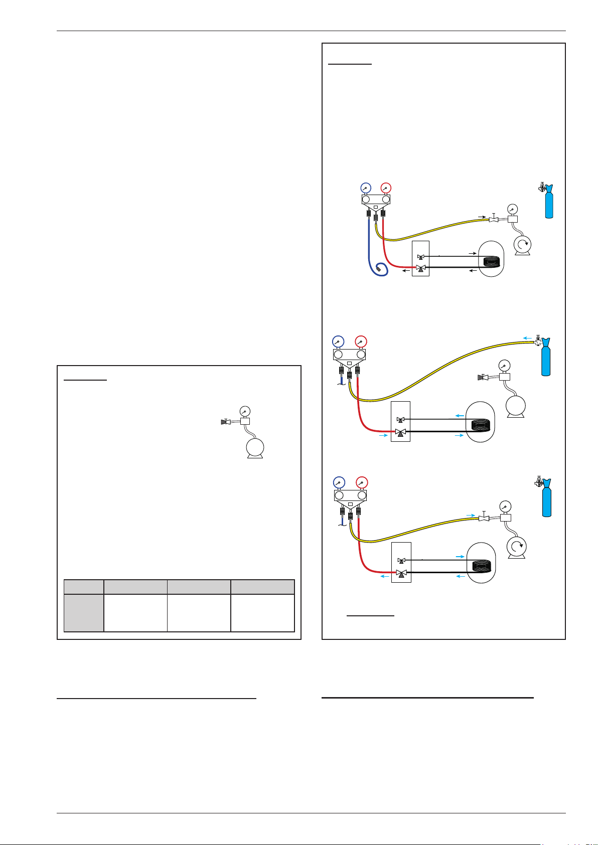
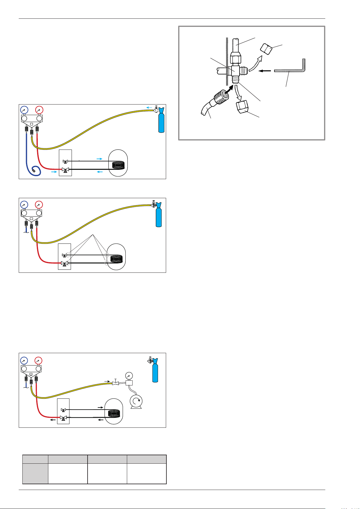
ANNEX 2
Method 3 empty
- Connect the high pressure hose to the Manifold,
("Gas" connection). A valve must be mounted on
the exible hose from the vacuum pump in order
to isolate it.
a) Pump down to the desired value (see table ANNEX 1),
Manometer kit
(Manifold)
(manifold)
Low
Basse
pressure
pression
Lo
Hi
Haute
pressure
pression
High
UE
Connection
Liaison...
Liquid
liquide
gaz
Gas
MH
Vacuum gauge
Vacuomètre
Vacuum pump
Pompe à vide
b) Stop the vacuum pump, close the valve end of
the service hose (yellow). Connect the hose to the
expansion valve of the nitrogen bottle, inject 2 bars,
close the exible hose valve,
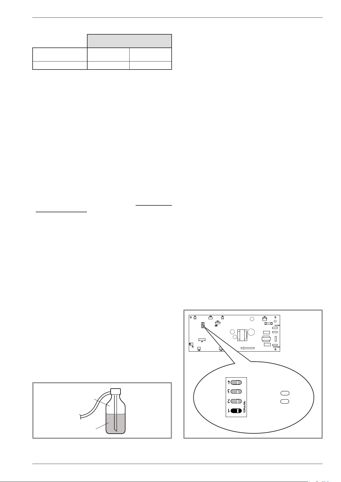
ANNEX 1
Method for calibration and control of a vacuum
pump
- Check the oil level of the
vacuum pump.
- Connect the vacuum pump
with the vacuum gauge
Flexible
Clogged
exible
bouché
hose
Vacuum
gauge
Vacuomètre
Vacuum
Pompe
pump
à vide
according to the scheme.
- Pump down during 3 minutes.
- After 3 minutes, the pump reaches its threshold
value and the vacuum gauge needle does not move.
- Compare the obtained pressure with the value of the
table. Depending on the temperature, this pressure
must be less than the value indicated in the table.
=> If it’s not the case, replace the gasket, exible
hose or the pump.
T °C 5°C<T<10°C 10°C<T<15°C 15°C < T
Pmax
- bar . .
- mbar
. . . 0.009 . . .
. . . . . 9 . . . . .
. . . 0.015 . . .
. . . . 15 . . . .
. . . 0.020. . .
. . . .20 . . . .
Nitrogen
Hi
Haute
pressure
pression
High
UE
Connection
Liaison...
Liquid
liquide
Gas
gaz
MH
Lo
Azote
c) Reconnect the exible hose to the vacuum pump,
turn on and gradually open the hose valve.
Lo
Hi
Haute
pressure
pression
High
UE
Connection
Liaison...
Liquid
liquide
gaz
Gas
MH
d) Repeat this at least three times.
" Reminder : It’s strictly forbidden to perform
these operations with refrigerant.
2.7.1 Commissioning procedure
• Check before connecting
"Gas" connection control (large diameter).
- Connect the "Gas" connection to the outdoor unit.
- Blow dry nitrogen into the "Gas" connection and
observe this end:
If water or impurities emerge, use a new refrigerant
connection.
Otherwise, perform the are and connect immediately
the refrigerant connection to the hydraulic unit.
Installation and operating manual "1572 - EN" - 19 -
"Liquid" connection control (small diameter).
- Connect the "Liquid" connection to the outdoor unit.
- Blow dry nitrogen into "Gas" connection – condensor
- "Liquid" connection assembly and Observe this
end (Outdoor unit side).
If water or impurities emerge, use a new refrigerant
connection.
Otherwise, perform the are and connect immediately
the refrigerant connection to the outdoor unit.
Heat pump air/water split 2 services alféa excellia duo
• First seal test
- Remove the protective plugs (B) from the charging
hole (Schrader) in the "Gas" valve (large diameter).
- Connect the high pressure hose to the Manifold.
- Connect the bottle of nitrogen to the Manifold
(Use only dry nitrogen type U).
- Pressurize the refrigerant circuit with nitrogen
(10 bar maximum) ("Gas" connection – condensor "Liquid" connection assembly).
- Let the circuit under pressure for 30 minutes.
Nitrogen
Hi
Haute
pressure
pression
High
UE
Connection
Liaison...
Liquid
liquide
Gas
gaz
MH
Lo
Azote
Max. 10 bar
10 bars max.
during 30 mn mini.
30 mn mini
- Search for leaks with a leak detector product, repair
and repeat the test.
Hi
Haute
pressure
pression
High
UE
Leak control
Liaison...
liquide
gaz
Vanne fermée,
Contrôle pression
Contrôle
d’étanchéité
MH
Closed valve,
pressure control
Lo
- When the pressure is stable and leakage is excluded,
drain nitrogen letting a pressure above atmospheric
pressure (0,2 to 0,4 bar).
• Creating a vacuum and lling the refrigeration
connections with gas
- If necessary, calibrate the Manifold gauge to 0 bar.
Adjust the vacuum gauge to the atmospheric pressure
(around 1013 mbar).
- Connect the vacuum pump to the Manifold. Connect
a vacuum gauge if the vacuum pump is not equipped.
Hi
Haute
pressure
pression
High
UE
Liaison...
Connection
Liquid
liquide
gaz
Gas
MH
Vacuum gauge
Vacuomètre
Vacuum pump
Vacuum pump
Pompe à vide
Lo
- Create a vacuum until the residual pressure* in the
circuit falls below the value given in the following table.
(* measured with the vacuum gauge).
T °C 5°C<T<10°C 10°C<T<15°C 15°C < T
Pmax
- bar . .
- mbar
. . . 0.009 . . .
. . . . . 9 . . . . .
. . . 0.015 . . .
. . . . 15 . . . .
. . . 0.020 . . .
. . . .20 . . . . .
Refrigeration connecxion (Gas)
Refrigeration connexion
Plug (A)
3-way valve
Hex / Allen key of 4mm
Load orifice
Service hose (blue)
High pressure hose (red)
fitted with valve push-button
gure 19 - Connection of the hose on the "Gaz" valve
Plug (B)
- Let the pump continue to operate for another
30 minutes minimum after reaching the vacuum.
- Close the Manifold valve and then stop the vacuum
pump without disconnecting any of the hoses in
place.
" If the outdoor temperature is between +5 and
+10 °C, use method 3 empty (see ANNEX 2).
- Remove the access plugs (A) from the valve controls.
- If an additional charge is requires, add the additional
charge before lling the hydraulic unit with gas. Please
refer to the para. "Additional charge", page 21.
- First of all fully open the "Liquid" valve (small)
and then the "Gas" valve (large) using a hex key
(counterclockwise direction) without forcing
excessively against the stop.
- Remove the hose rapidly to the Manifold.
- Ret the 2 original caps (be sure they are clean) and
tighten them to the recommended tightening torque
(gure 17, page 17). The sealing is performed in the
caps only metal to metal.
The outdoor unit does not contain any additional
refrigerant, enabling the installation to be purged.
Flushing is strictly forbidden.
2.7.2 Sealing test
The sealing test must be performed with a certied gas
detector (sensitivity 5g/year).
Once the refrigeration circuit has been gassed as
described above, check that all the refrigeration connectors
are gas-tigh (4 connectors). If the arings have been made
correctly, there should be no leaks. Eventually, check the
tightness of the refrigerant valves caps.
" If there is a leak:
- Bring the gas into the outdoor unit (pump down).
The pressure should not drop below atmospheric
pressure (0 bar to read on Manifold) so as not to
contaminate the recovered gas with air or moisture.
- Make the connection again.
- Repeat the commissioning procedure.
- 20 -
Installation and operating manual "1572 - EN"
Heat pump air/water split 2 services alféa excellia duo
2.7.3 Additional charge
50 g of R410A
per additional meter
Length of
the connections
Additional charge none 250 g
15 m 20 m max.
The charge in the outdoor units corresponds to the
maximum distances between the outdoor unit and the
hydraulic unit dened in page 18. If the distances
are greater, an additional charge of R410A is required.
The additional charge depends on the distance
between the outdoor unit and the hydraulic unit for
each type of appliance. The additional charge of R410A
must necessarily be made by an approved refrigeration
engineer.
• Example of additional charge :
An outdoor unit 17 m away from the hydraulic unit will
require an additional charge of :
Additional charge = (17 - 15) x 50 = 100 g.
The charge must be introduced after creating the
vacuum and before the hydraulic unit is lled with gas,
as follows :
- Disconnect the vacuum pump (yellow hose) and
connect a bottle of R410A instead in the liquid
extraction position.
- Open the bottle’s valve.
- Bleed the yellow hose by loosening it slightly on the
Manifold side.
- Place the bottle on scales with a minimum accuracy
of 10 g. Note the weight.
- Carefully open the blue valve slightly and check the
value shown on the scales.
- As soon as the value displayed has dropped by the
value for the calculated additional charge, close the
bottle and disconnect it.
- Then rapidly disconnect the hose connected to the
appliance.
- Proceed to ll the hydraulic unit with gas.
" Warning
• Only use R410A !
• Only use tools suitable for R410A
(set of manometers).
• Always charge in the uid phase.
• Never exceed the length or the maximum difference
in level.
2.7.4 Pump down operation (Refrigerant collecting
operation) outdoor unit
Perform the following procedures to collect the
refrigerant.
- 1- Turn OFF the start/stop switch
(ref. 3, gure 7, page 10).
- 2- Remove the front panel.
Then turn ON the DIP SW 1 on the interface card.
- 3- Turn ON the start/stop switch.
(Green and Red LED on the board start ashing ;
1 sec. on / 1 sec. off repeated).
- 4- The outdoor unit begins cooling operation
about 3 minutes after switching ON.
Close the "Liquid" valve on the outdoor unit 1 minute
after operation starts.
- 5- Close the "Gas" valve on the outdoor unit
1-2 minutes after closing the "Liquid" valve, while the
outdoor unit keeps running.
- 6- Disconnect the power supply.
Remarks :
- Make sure to turn OFF the start/stop switch before
touching DIP SW.
- The pump down operation cannot be activated even
if DIP SW is changed while heat pump's power is on.
- Do not forget to turn back DIP SW 1 on the interface
card to OFF, after the pump down operation has been
completed.
- When the pump down operation is repeated,
temporarily turn OFF the start/stop switch after opening
the closed valves (both "Liquid" and "Gas").
- Then turn ON the start/stop switch again after
2-3 minutes and perform the pump down operation.
Interface card
DIP SW
LED2
Gas
R410A
OFF
ON
Liquid
gure 21 - "Gas" bottle R410A
Installation and operating manual "1572 - EN" - 21 -
gure 20 - Location of DIP switches and diodes
on the hydraulic unit interface card
(green)
LED1
(red)
Heat pump air/water split 2 services alféa excellia duo
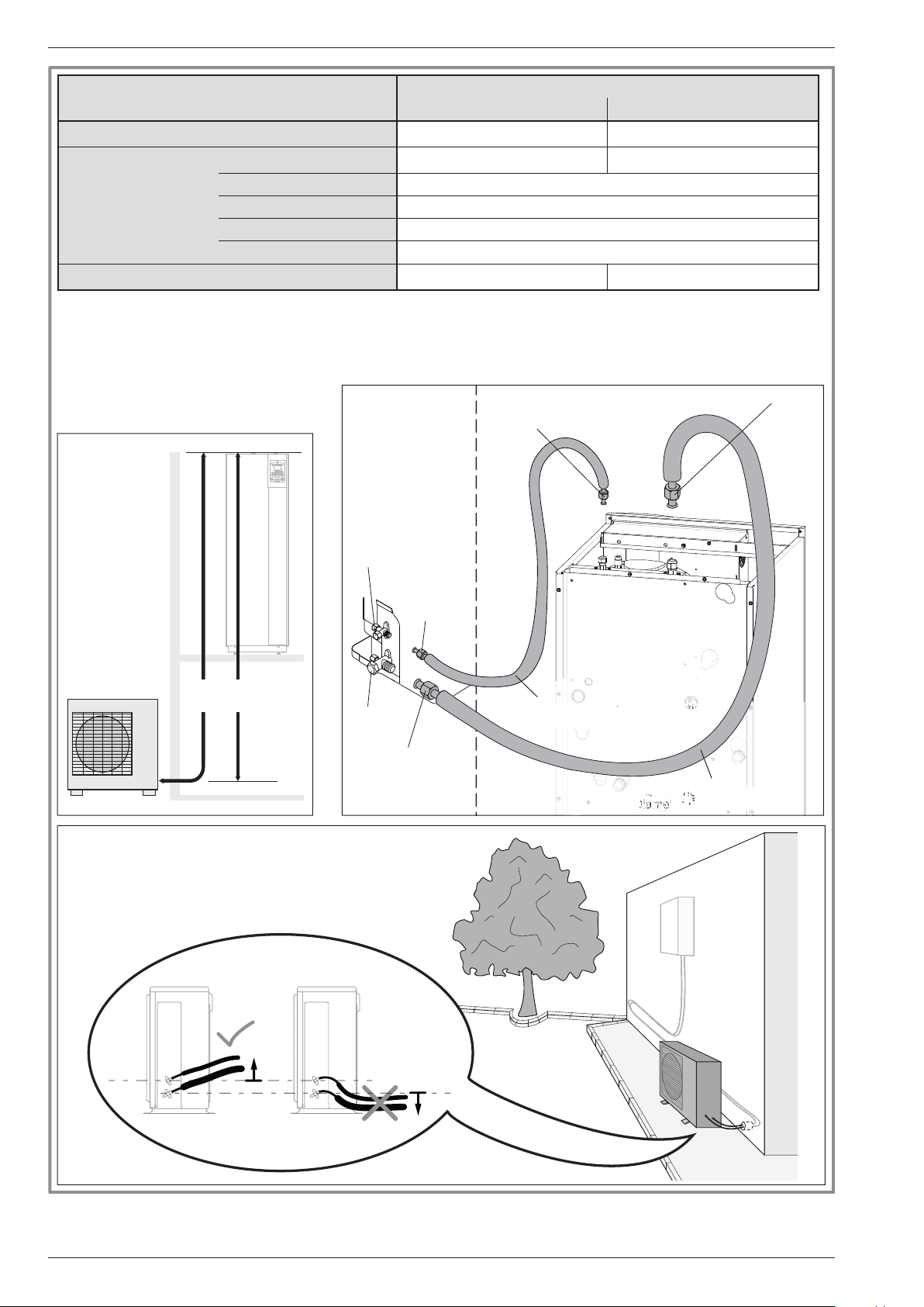
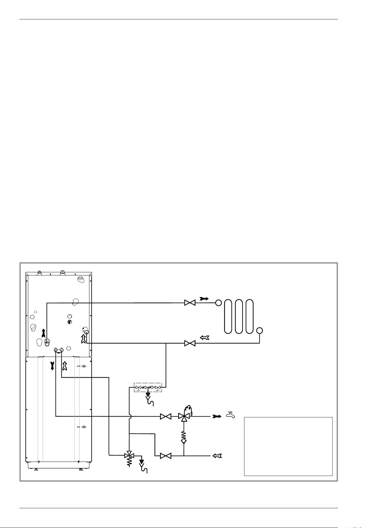
2.8 Hydraulic connecting
2.8.1 General
The connection must comply with good trade practice
according to local building regulations.
The heating circulating pump is built into the hydraulic unit.
Connect the central heating pipes to the appliance,
complying with the direction of circulation.
The pipe between the heat pump and the heat collector
must be at least one inch in diameter (26x34 mm).
Calculate the diameter of the pipes according to the
ow rates and the lengths of the hydraulic systems.
Tightening torque: 15 to 35 Nm.
Use union connectors to facilitate removing the hydraulic
unit.
Preferentially use connection hoses to avoid transmitting
noise and vibrations to the building.
Connect the drains from the drain valve and the safety
valve to the main sewer system.
Verify the correct functioning of the expansion system.
Control the vessel pressure (precharge 1 bar) and the
safety valve setting.
Reminder: Seal everything when tting in accordance
with prevailing trade practice for plumbing work:
- Use suitable seals (bre seals, o-rings).
- Use Teon tape or hemp.
- Use sealing paste (synthetic depending on the case).
The use of glycol is not necessary. If you are using a
glycol/water mix, provide for an annual check on the
quantity of glycol. Use monopropylene glycol only.
Never use monoethylene glycol.
" In certain installations, the presence of different
metals can cause corrosion problems; the
formation of metal particles and sludge in the
hydraulic circuit is then seen.
" In this case, it is advisable to use a corrosion
inhibitor in the proportions indicated by its
manufacturer.
- Please refer to the chapter "Treatment of domestic
and heating water" in our price catalogue.
" It is also necessary to ensure that the treated
water does not become aggressive.
Ø 26x34
1" Male
Ø 20x27
3/4" Male
GS
D
MT
CAR
R1
Legend:
CAR : Non-return valve.
D : Shut-off.
GS : Safety unit.
MT : Thermostatic mixer valve.
R1 : Heating circuit.
- 22 -
gure 22 - Overall hydraulic layout
Installation and operating manual "1572 - EN"
 Loading...