


PRIME X370-PROMotherboard

E12577
Revised Edition v2
February 2017
Copyright© 2017 ASUSTeK COMPUTER INC. All Rights Reserved.
No part of this manual, including the products and software described in it, may be reproduced, transmitted, transcribed, stored in a retrieval system, or translated into any language in any form or by any means, except documentation kept by the purchaser for backup purposes, without the express written permission of ASUSTeK COMPUTER INC. (“ASUS”).
Product warranty or service will not be extended if: (1) the product is repaired, modified or altered, unless such repair, modification of alteration is authorized in writing by ASUS; or (2) the serial number of the product is defaced or missing.
ASUS PROVIDES THIS MANUAL “AS IS” WITHOUT WARRANTY OF ANY KIND, EITHER EXPRESS OR IMPLIED, INCLUDING BUT NOT LIMITED TO THE IMPLIED WARRANTIES OR CONDITIONS OF MERCHANTABILITY OR FITNESS FOR A PARTICULAR PURPOSE. IN NO EVENT SHALL ASUS, ITS DIRECTORS, OFFICERS, EMPLOYEES OR AGENTS BE LIABLE FOR ANY INDIRECT, SPECIAL, INCIDENTAL, OR CONSEQUENTIAL DAMAGES (INCLUDING DAMAGES FOR LOSS OF PROFITS, LOSS OF BUSINESS, LOSS OF USE OR DATA, INTERRUPTION OF BUSINESS AND THE LIKE), EVEN IF ASUS HAS BEEN ADVISED OF THE POSSIBILITY OF SUCH DAMAGES ARISING FROM ANY DEFECT OR ERROR IN THIS MANUAL OR PRODUCT.
SPECIFICATIONS AND INFORMATION CONTAINED IN THIS MANUAL ARE FURNISHED FOR INFORMATIONAL USE ONLY, AND ARE SUBJECT TO CHANGE AT ANY TIME WITHOUT NOTICE, AND SHOULD NOT BE CONSTRUED AS A COMMITMENT BY ASUS. ASUS ASSUMES NO RESPONSIBILITY OR LIABILITY FOR ANY ERRORS OR INACCURACIES THAT MAY APPEAR IN THIS MANUAL, INCLUDING THE PRODUCTS AND SOFTWARE DESCRIBED IN IT.
Products and corporate names appearing in this manual may or may not be registered trademarks or copyrights of their respective companies, and are used only for identification or explanation and to the owners’ benefit, without intent to infringe.
Offer to Provide Source Code of Certain Software
This product contains copyrighted software that is licensed under the General Public License (“GPL”), under the Lesser General Public License Version (“LGPL”) and/or other Free Open Source Software Licenses. Such software in this product is distributed without any warranty to the extent permitted by the applicable law. Copies of these licenses are included in this product.
Where the applicable license entitles you to the source code of such software and/or other additional data, you may obtain it for a period of three years after our last shipment of the product, either
(1)for free by downloading it from https://www.asus.com/support/
or
(2)for the cost of reproduction and shipment, which is dependent on the preferred carrier and the location where you want to have it shipped to, by sending a request to:
ASUSTeK Computer Inc.
Legal Compliance Dept.
15 Li Te Rd.,
Beitou, Taipei 112
Taiwan
In your request please provide the name, model number and version, as stated in the About Box of the product for which you wish to obtain the corresponding source code and your contact details so that we can coordinate the terms and cost of shipment with you.
The source code will be distributed WITHOUT ANY WARRANTY and licensed under the same license as the corresponding binary/object code.
This offer is valid to anyone in receipt of this information.
ASUSTeK is eager to duly provide complete source code as required under various Free Open Source Software licenses. If however you encounter any problems in obtaining the full corresponding source code we would be much obliged if you give us a notification to the email address gpl@asus.com, stating the product and describing the problem (please DO NOT send large attachments such as source code archives, etc. to this email address).
ii

Contents
Safety information....................................................................................................... |
v |
About this guide.......................................................................................................... |
vi |
PRIME X370-PRO specifications summary............................................................ |
viii |
Package contents...................................................................................................... |
xii |
Installation tools and components.......................................................................... |
xiii |
Chapter 1: |
Product Introduction |
|
|
1.1 |
Motherboard overview............................................................................... |
1-1 |
|
|
1.1.1 |
Before you proceed..................................................................... |
1-1 |
|
1.1.2 |
Motherboard layout...................................................................... |
1-2 |
|
1.1.3 |
Central Processing Unit (CPU).................................................... |
1-4 |
|
1.1.4 |
System memory........................................................................... |
1-4 |
|
1.1.5 |
Expansion slots............................................................................ |
1-6 |
|
1.1.6 |
Jumpers and Headers................................................................. |
1-8 |
|
1.1.7 |
Internal connectors.................................................................... |
1-10 |
Chapter 2: |
Basic Installation |
|
|
2.1 |
Building your PC system........................................................................... |
2-1 |
|
|
2.1.1 |
Motherboard installation.............................................................. |
2-1 |
|
2.1.2 |
CPU installation........................................................................... |
2-3 |
|
2.1.3 |
CPU heatsink and fan assembly installation................................ |
2-4 |
|
2.1.4 |
DIMM installation......................................................................... |
2-6 |
|
2.1.5 |
ATX power connection................................................................. |
2-7 |
|
2.1.6 |
SATA device connection.............................................................. |
2-7 |
|
2.1.7 |
Front I/O connector...................................................................... |
2-8 |
|
2.1.8 |
Expansion card installation.......................................................... |
2-9 |
|
2.1.9 |
M.2 installation........................................................................... |
2-10 |
2.2 |
Motherboard rear and audio connections.............................................. |
2-11 |
|
|
2.2.1 |
Rear I/O connection................................................................... |
2-11 |
|
2.2.2 |
Audio I/O connections................................................................ |
2-12 |
2.3 |
Starting up for the first time.................................................................... |
2-15 |
|
2.4 |
Turning off the computer......................................................................... |
2-15 |
|
Chapter 3: |
BIOS Setup |
|
|
3.1 |
Knowing BIOS............................................................................................. |
3-1 |
|
3.2 |
BIOS setup program................................................................................... |
3-2 |
|
|
3.2.1 |
EZ Mode...................................................................................... |
3-3 |
|
3.2.2 |
Advanced Mode........................................................................... |
3-4 |
|
3.2.3 |
QFan Control............................................................................... |
3-7 |
3.3 |
My Favorites................................................................................................ |
3-9 |
|
iii

3.4 |
Main menu................................................................................................. |
3-11 |
|
3.5 |
Ai Tweaker menu...................................................................................... |
3-11 |
|
3.6 |
Advanced menu........................................................................................ |
3-17 |
|
|
3.6.1 |
CPU Configuration..................................................................... |
3-17 |
|
3.6.2 |
NB Configuration....................................................................... |
3-18 |
|
3.6.3 |
SATA Configuration................................................................... |
3-18 |
|
3.6.4 |
Onboard Devices Configuration................................................. |
3-19 |
|
3.6.5 |
APM Configuration..................................................................... |
3-20 |
|
3.6.6 |
Network Stack............................................................................ |
3-20 |
|
3.6.7 |
HDD/SSD SMART Information.................................................. |
3-21 |
|
3.6.8 |
USB Configuration..................................................................... |
3-21 |
|
3.6.9 |
AMD CBS.................................................................................. |
3-21 |
3.7 |
Monitor menu............................................................................................ |
3-22 |
|
3.8 |
Boot menu................................................................................................. |
3-25 |
|
3.9 |
Tool menu.................................................................................................. |
3-29 |
|
|
3.9.1 |
ASUS EZ Flash 3 Utility............................................................. |
3-29 |
|
3.9.2 |
ASUS Overclocking Profile........................................................ |
3-29 |
|
3.9.3 |
ASUS SPD Information.............................................................. |
3-29 |
3.10 |
Exit menu................................................................................................... |
3-30 |
|
3.11 |
Updating BIOS.......................................................................................... |
3-31 |
|
|
3.11.1 |
EZ Update.................................................................................. |
3-31 |
|
3.11.2 |
ASUS EZ Flash 3....................................................................... |
3-32 |
|
3.11.3 |
ASUS CrashFree BIOS 3.......................................................... |
3-34 |
Chapter 4: |
RAID Support |
|
|
4.1 |
AMD RAID Array configurations............................................................... |
4-1 |
|
|
4.1.1 |
RAID definitions........................................................................... |
4-1 |
|
4.1.2 |
Installing Serial ATA hard disks................................................... |
4-2 |
4.1.3Setting up RAID from RAIDXpert2 Configuration Utility in UEFI
|
|
BIOS............................................................................................ |
4-2 |
|
4.1.4 |
AMD RAID Array configuration in Option ROM utility.................. |
4-5 |
4.2 |
Creating a RAID driver disk..................................................................... |
4-10 |
|
|
4.2.1 |
Creating a RAID driver disk in Windows® ................................. |
4-10 |
Appendix
Notices ..................................................................................................................... |
A-1 |
ASUS contact information...................................................................................... |
A-5 |
iv

Safety information
Electrical safety
•To prevent electrical shock hazard, disconnect the power cable from the electrical outlet before relocating the system.
•When adding or removing devices to or from the system, ensure that the power cables for the devices are unplugged before the signal cables are connected. If possible, disconnect all power cables from the existing system before you add a device.
•Before connecting or removing signal cables from the motherboard, ensure that all power cables are unplugged.
•Seek professional assistance before using an adapter or extension cord. These devices could interrupt the grounding circuit.
•Ensure that your power supply is set to the correct voltage in your area. If you are not sure about the voltage of the electrical outlet you are using, contact your local power company.
•If the power supply is broken, do not try to fix it by yourself. Contact a qualified service technician or your retailer.
Operation safety
•Before installing the motherboard and adding devices on it, carefully read all the manuals that came with the package.
•Before using the product, ensure all cables are correctly connected and the power cables are not damaged. If you detect any damage, contact your dealer immediately.
•To avoid short circuits, keep paper clips, screws, and staples away from connectors, slots, sockets and circuitry.
•Avoid dust, humidity, and temperature extremes. Do not place the product in any area where it may become wet.
•Place the product on a stable surface.
•If you encounter technical problems with the product, contact a qualified service technician or your retailer.
v

About this guide
This user guide contains the information you need when installing and configuring the motherboard.
How this guide is organized
This guide contains the following parts:
1.Chapter 1: Product Introduction
This chapter describes the features of the motherboard and the new technology it supports. It includes description of the switches, jumpers, and connectors on the motherboard.
2.Chapter 2: Basic Installation
This chapter lists the hardware setup procedures that you have to perform when installing system components.
3.Chapter 3: BIOS Setup
This chapter tells how to change system settings through the BIOS Setup menus. Detailed descriptions of the BIOS parameters are also provided.
4.Chapter 4: RAID Support
This chapter describes the RAID configurations.
Where to find more information
Refer to the following sources for additional information and for product and software updates.
1.ASUS website
The ASUS website (www.asus.com) provides updated information on ASUS hardware and software products.
2.Optional documentation
Your product package may include optional documentation, such as warranty flyers, that may have been added by your dealer. These documents are not part of the standard package.
vi

Conventions used in this guide
To ensure that you perform certain tasks properly, take note of the following symbols used throughout this manual.
DANGER/WARNING: Information to prevent injury to yourself when trying to complete a task.
CAUTION: Information to prevent damage to the components when trying to complete a task.
IMPORTANT: Instructions that you MUST follow to complete a task.
NOTE: Tips and additional information to help you complete a task.
Typography
Bold text |
Indicates a menu or an item to select. |
Italics |
Used to emphasize a word or a phrase. |
<Key> |
Keys enclosed in the less-than and greater-than sign |
|
means that you must press the enclosed key. |
|
Example: <Enter> means that you must press the Enter or |
|
Return key. |
<Key1> + <Key2> + <Key3> |
If you must press two or more keys simultaneously, the key |
|
names are linked with a plus sign (+). |
vii

PRIME X370-PRO specifications summary
|
AM4 socket for AMD Ryzen™/7th Generation A-series/Athlon™ Processorss |
|
CPU |
Supports CPU up to 8 cores* |
|
* Due to CPU limitation, CPU cores supported varies by processor. |
||
|
||
|
** Refer to www.asus.com for the AMD CPU support list. |
|
|
|
|
Chipset |
AMD X370 Chipset |
|
|
|
|
|
AMD Ryzen™ Processors |
|
|
4 x DIMM, max. 64GB DDR4 3200(O.C.)/2933(O.C.)2666/2400/2133 MHz, ECC |
|
|
and non-ECC, un-buffered memory |
|
|
AMD 7th Generation A-series/Athlon™ Processors |
|
Memory |
4 x DIMM, max. 64GB DDR4 2400/2133 MHz, non-ECC, un-buffered memory |
|
|
Dual channel memory architecture |
|
|
* Refer to www.asus.com for the Memory QVL (Qualified Vendors List) Please refer to |
|
|
Memory QVL (Qualified Vendors List) for details. |
|
|
** Hyper DIMM support is subject to the physical characteristics of individual CPUs. |
|
|
|
|
|
AMD Ryzen™ Processors |
|
|
2 x PCI Express 3.0/2.0 x16 slots (single at x16 or dual at x8/x8 mode) |
|
|
AMD 7th Generation A-series/Athlon™ Processors |
|
Expansion |
1 x PCI Express 3.0/2.0 x16 slot (single at x8) |
|
slots |
AMD X370 chipset |
|
|
1 x PCI Express 2.0 x16 slot (max. at x4 mode)* |
|
|
3 x PCI Express 2.0 x1 slots |
|
|
* PCIeX16_3 slot shares bandwidth with PCIeX1_1 and PCIeX1_3. |
|
|
|
|
|
Integrated AMD Radeon™ R Series Graphics in the 7th Generation A-Series APU |
|
|
Multi-VGA output support: DisplayPort/HDMI ports |
|
VGA |
Supports DisplayPort 1.2 with max. resolution 4096 x 2160@60Hz |
|
Supports HDMI 1.4b with max. resolution 4096 x 2160 @24Hz / 2560 x 1600 |
||
|
||
|
@60Hz |
|
|
Maximum shared memory of 2048MB |
|
|
|
|
|
AMD Ryzen™ Processors |
|
Multi-GPU |
Supports NVIDIA® 2-Way SLI™ Technology |
|
Supports AMD CrossFireX™ Technology |
||
support |
||
AMD 7th Generation A-series/Athlon™ Processors |
||
|
||
|
Supports AMD CrossFireX™ Technology |
AMD Ryzen™ Processors
-1 x M.2 Socket 3 with M Key, type 2242/2260/2280/22110 (PCIE 3.0 x4 and SATA modes) storage devices support
Storage |
AMD 7th Generation A-series/Athlon™ Processors |
|
- 1 x M.2 Socket 3 with M Key, type 2242/2260/2280/22110(PCIE 3.0 x2 and SATA |
||
|
||
|
modes) storage devices support |
|
|
AMD X370 chipset with RAID 0, 1, 10 support |
|
|
- 8 x SATA 6.0 Gb/s ports (gray) |
|
|
|
|
|
(continued on the next page) |
viii

PRIME X370-PRO specifications summary
LAN |
Intel® I211AT Gigabit LAN |
Realtek® S1220A 8-channel high definition audio CODEC
-Audio Shielding: Ensures precision analog/digital separation and greatly reduces multi-lateral interference
-Dedicated audio PCB layers: Separate layers for left and right channels to guard the quality of the sensitive audio signals
Audio |
- Premium Japanese audio capacitors: Provide warm, natural and immersive sound |
|
with exceptional clarity and fidelity |
|
- Supports jack-detection, multi-streaming, front panel jack-retasking |
|
- High quality 120dB SNR stereo playback output (Line-out@back) & 113dB SNR |
|
input (Line-in) support |
|
- Optical S/PDIF out port at back I/O |
|
|
|
AMD Ryzen™/7th Generation A-series/Athlon™ Processors |
|
- 4 x USB 3.0/2.0 ports (4 ports at back panel[blue]) |
|
AMD X370 Chipset |
|
- 1 x USB 3.1/3.0/2.0 front panel connector |
USB |
- 4 x USB 3.0/2.0 ports (2 ports at mid-board; 2 ports at back panel,Type-A[blue] |
|
|
|
and Type-C) |
|
- 4 x USB 2.0/1.1 ports at mid-board |
|
ASMedia USB 3.1 controllers |
|
- 2 x USB 3.1/3.0/2.0 ports (2 ports at back panel[teal blue]) |
|
|
|
<Performance Optimization> |
5-Way Optimization
-Whole system optimization with a single click! Perfectly consolidates TPU, EPU,
DIGI+ VRM, Fan Xpert 4, and Turbo App.
DIGI+ VRM
- 6+4 Phase digital power design
TPU
- Auto Tuning
ASUS
Exclusive EPU
Features - EPU
Fan Xpert 4 featuring system performance tuning, network priority, and audio scene configuration for selected applications
Turbo App featuring system performance tuning, network priority, and audio scene configuration for selected applications.
Gaming Scenario
AURA
- Bright up your Build
Audio Features
- Audio that roars on the battlefield
(continued on the next page)
ix

PRIME X370-PRO specifications summary
|
EZ DIY |
|
|
UEFI BIOS EZ Mode |
|
|
- featuring friendly graphics user interface |
|
|
- ASUS CrashFree BIOS 3 |
|
ASUS Exclusive |
- ASUS EZ Flash 3 |
|
Features |
Q-Design |
|
|
||
|
- ASUS Q-Shield |
|
|
- ASUS Q-Slot |
|
|
- ASUS Q-DIMM |
|
|
- ASUS Q-Connector |
|
|
|
|
|
Special Features: |
|
|
ASUS SafeSlot |
|
|
- Protect your graphics card Investment |
|
|
ASUS 5X Protection III |
|
|
- ASUS SafeSlot Core - Fortified PCIe with solid soldering |
|
|
- ASUS LANGuard - Protects against LAN surges, lightning strikes and |
|
|
static-electricity discharges! |
|
ASUS Special |
- ASUS Overvoltage Protection - World-class circuit-protecting power |
|
Features |
design |
|
|
- ASUS DIGI+ VRM - 6+4 Phase digital power design |
|
|
- ASUS DRAM Overcurrent Protection: Enhanced DRAM overcurrent |
|
|
protection |
|
|
- ASUS Stainless - Steel Back I/O: 3X corrosion-resistance for greater |
|
|
durability! |
|
|
- ASUS ESD Guards - Enhanced ESD protection |
|
|
- AI Suite 3 |
|
|
- Ai Charger |
|
|
|
|
ASUS Quiet |
Quiet Thermal Design: |
|
- ASUS Fan Xpert 4 |
||
Thermal |
||
Solution |
- Stylish Fanless Design: Chipset Heat-sink & MOS Heat-sink solution |
|
|
||
|
|
|
|
Precision Tweaker 2: |
|
|
- vVDDCR CPU: Adjustable CPU voltage at 0.00625V increment |
|
ASUS Exclusive |
- vVDDCR SOC: Adjustable CPU/NB voltage at 0.00625V increment |
|
Overclocking |
- vDRAM Bus: Adjustable DRAM voltage at 0.005V increment |
|
Features |
||
|
||
|
Overclocking Protection: |
|
|
- ASUS C.P.R.(CPU Parameter Recall) |
|
|
(continued on the next page) |
x
PRIME X370-PRO specifications summary
|
|
1 x PS/2 Keyboard/Mouse Combo port |
|
|
|
1 x DisplayPort |
|
|
|
1 x HDMI port |
|
|
|
1 x Intel LAN (RJ45) port |
|
Back Panel I/O |
2 x USB 3.1/3.0/2.0 port (teal blue, Type A) |
||
Ports |
1 x USB 3.0/2.0 port (Type C) |
||
|
|
||
|
|
5x USB 3.0/2.0 ports (blue, Type A) |
|
|
|
1 x Optical S/PDIF out |
|
|
|
5 x Audio Jacks(Line in,Front Speaker Out,Mic in,Center/Subwoofer,Rear |
|
|
|
Speaker Out) |
|
|
|
|
|
|
|
1 x USB 3.1/3.0/2.0 front panel connector |
|
|
|
1 x USB 3.0/2.0 connectors support additional 2 USB ports (19-pin) |
|
|
|
2 x USB 2.0/1/1 connectors support additional 4 USB ports |
|
|
|
1 x M.2 Socket 3 for M Key, type 2242/2260/2280/22110 devices support, |
|
|
|
(both SATA & PCIE mode) |
|
|
|
8 x SATA 6.0Gb/s connectors (gray) |
|
|
|
1 x CPU Fan header (4-pin) for both 3-pin(DC mode) and 4-pin(PWM mode) |
|
|
|
CPU coolers control with auto detection support |
|
|
|
1 x CPU OPT Fan header (4-pin) |
|
Internal I/O |
1 x AIO Pump header (4-pin) |
||
1 x W_PUMP+ header (4-pin) |
|||
connectors |
|||
2 x Chassis Fan connectors (4-pin) for both 3-pin(DC mode) and 4-pin(PWM |
|||
|
|
||
|
|
mode) coolers control with auto detection support |
|
|
|
1 x Aura RGB header |
|
|
|
1 x Front panel audio connector (AAFP) |
|
|
|
1 x TPM connector |
|
|
|
1 x COM connector |
|
|
|
1 x 24-pin EATX Power connector |
|
|
|
1 x 8-pin EATX 12V Power connector |
|
|
|
1 x System Panel |
|
|
|
1 x Clear CMOS header |
|
|
|
|
|
|
|
128 Mb Flash ROM, UEFI AMI BIOS, PnP, DMI3.0, WfM2.0, SM BIOS 3.0, |
|
|
|
ACPI 6.1, Multi-language BIOS, ASUS EZ Flash 3, CrashFree BIOS 3, F11 |
|
BIOS Features |
EZ Tuning Wizard, F6 Qfan Control, F3 My Favorites, Last Modified log, |
||
|
|
F12 PrintScreen, and ASUS DRAM SPD (Serial Presence Detect) memory |
|
|
|
information |
|
|
|
|
|
Manageability |
WfM 2.0, DMI 3.0, WOL by PME, PXE |
||
|
|
|
|
|
|
Drivers |
|
Support DVD |
ASUS Utilities |
||
contents |
EZ Update |
||
|
|
Anti-virus software (OEM version) |
|
|
|
|
|
OS support |
Windows® 10 64-bit |
||
Form factor |
ATX Form Factor, 12”x 9.6” (30.5cm x 24.4cm) |
||
|
|
|
|
• Specifications are subject to change without notice.
• Visit the ASUS website for the software manual.
xi
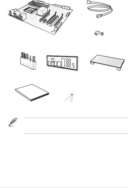
Package contents
Check your motherboard package for the following items:
Motherboard
4 x Serial ATA 6.0 Gb/s cables
ASUS PRIME X370-PRO motherboard
1 x M.2 screw package
1 x Q-Connector |
1 x ASUS Q-Shield |
1 x ASUS SLI HB BRIDGE(2-WAY-M) |
|
Manual |
|
|
|
|
|
|
|
User |
|
|
|
|
|
|
|
1 x User Manual |
|
1 x Support DVD |
|
•If any of the above items is damaged or missing, contact your retailer.
•The illustrated items above are for reference only. Actual product specifications may vary with different models.
xii
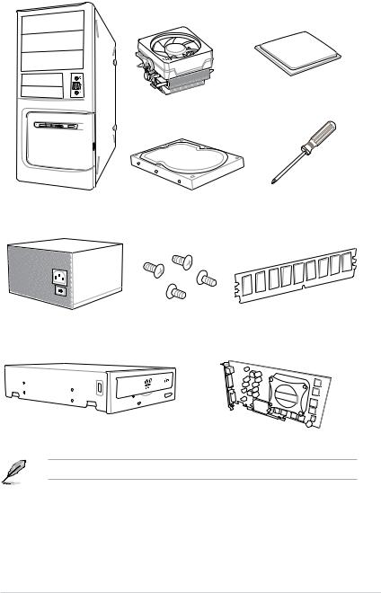
Installation tools and components
AMD AM4 CPU
AMD AM4 compatible CPU Fan
PC chassis |
SATA hard disk drive |
Phillips (cross) screwdriver |
Power supply unit |
1 bag of screws |
DIMM |
SATA optical disc drive (optional) |
Graphics card |
The tools and components in the table above are not included in the motherboard package.
xiii

xiv

Product Introduction |
1 |
1.1Motherboard overview
1.1.1Before you proceed
Take note of the following precautions before you install motherboard components or change any motherboard settings.
•Unplug the power cord from the wall socket before touching any component.
•Before handling components, use a grounded wrist strap or touch a safely grounded object or a metal object, such as the power supply case, to avoid damaging them due to static electricity.
•Hold components by the edges to avoid touching the ICs on them.
•Whenever you uninstall any component, place it on a grounded antistatic pad or in the bag that came with the component.
•Before you install or remove any component, ensure that the ATX power supply is switched off or the power cord is detached from the power supply. Failure to do so may cause severe damage to the motherboard, peripherals, or components.
Chapter 1
ASUS PRIME X370-PRO |
1-1 |

1 Chapter
1.1.2Motherboard layout
1 |
2 |
3 |
4 |
5 |
2 |
6 |
24.4cm(9.6in)
KBMS |
|
EATX12V |
CPU_FAN CPU_OPT |
|
|
DIGI |
|
+VRM |
|
EPU |
|
HDMI_DP |
|
USB3_C7 |
|
|
|
|
USB3_5 |
|
|
|
|
USB3.1_E12 |
ASM |
|
|
|
|
1143 |
|
|
|
LAN_USB3_34 |
|
|
|
|
AUDIO |
LANGuard |
AIOPUMP |
CHAFAN1 |
RGB HEADER |
|
|
|
BIOS |
|
|
|
|
|
128Mb |
|
Intel® |
22110 |
2280 |
2260 |
|
|
|
|
|
|
I211AT |
|
|
|
|
|
|
|
PCIEX16_1 |
|
SOCKET AM4 |
-pin module) |
-pin module) |
-pin module) |
-pin module) |
|
30.5cm(12in) |
|
DDR4DIMM A1 (64bit, 288 |
DDR4DIMM A2 (64bit, 288 |
DDR4DIMM B1 (64bit, 288 |
DDR4DIMM B2 (64bit, 288 |
C1 |
||
|
|
|
|
|
|
EATXPWR |
1 |
|
|
|
|
|
|
|
|
|
|
|
|
|
|
_ |
|
|
|
|
|
|
|
USB3.1 |
7 |
|
|
|
|
|
|
|
|
2242 |
M.2(SOCKET3) |
|
|
|
|
|
|
|
|
PRIME X370-PRO |
|
|
|
||
|
PCIEX1_1 |
|
|
|
|
|
|
AURA |
|
|
|
|
|
|
|
|
PCIEX1_2 |
|
|
|
AMD® |
78 |
|
Super |
|
|
|
X370 |
_ |
|
|
|
|
|
BATTERY |
|
SATA6G |
|
|
|
|
|
|
|
|
|
|
I/O |
|
|
|
|
|
56 |
8 |
|
|
|
PCIEX16_2 |
|
|
SATA6G34 |
|
|
|
|
|
|
|
|
|
Realtek® |
|
|
|
|
|
_ |
|
S1220A |
|
|
|
|
|
SATA6G |
|
|
|
|
TPU |
|
|
|
|
|
PCIEX1_3 |
|
|
|
|
SATA6G 12 |
|
|
|
|
|
|
|
|
|
|
|
|
PCIEX16_3 |
|
|
|
|
|
AAFP |
COM |
TPM |
USB34 USB12 USB3_12 |
CHA_FAN2 |
W_PUMP+ |
|
CLRTC |
|
T_SENSOR |
PANEL |
|
16 |
15 |
14 |
13 |
12 |
11 |
10 |
2 |
9 |
Refer to 1.1.9 Internal connectors and 2.2.1 Rear I/O connection for more information about rear panel connectors and internal connectors.
1-2 |
Chapter 1: Product Introduction |

Layout contents
Connectors/Jumpers/Buttons and switches/Slots |
Page |
|
1. |
ATX power connectors (24-pin EATXPWR; 8-pin EATX12V) |
1-14 |
2. |
CPU, CPU optional, AIO pump, W_pump+, and chassis fan connectors |
1-4 |
|
(4-pin CPU_FAN; 4-pin CPU_OPT; 4-pin AIO_PUMP; 4-pin W_PUMP+; |
|
|
4-pin CHA_FAN1-2) |
|
3. |
RGB header (4-pin RGB_HEADER) |
1-9 |
4. |
M.2 socket 3 |
1-17 |
5. |
AM4 socket |
1-4 |
6. |
DDR4 DIMM slots |
1-4 |
7. |
USB 3.1 connector (20 pin USB3.1_C1) |
1-12 |
8. |
Serial ATA 6 Gb/s connectors (7-pin SATA6G_12; SATA 6G_34; SATA |
1-10 |
|
6G_56; SATA 6G_78) |
|
9. |
System panel connector (20-5 pin PANEL) |
1-15 |
10. |
Clear RTC RAM jumper (2-pin CLRTC) |
1-8 |
11. |
Thermal sensor connector (2-pin T_SENSOR) |
1-16 |
12. |
USB 3.0 connector (20-1 pin USB3_12) |
1-12 |
13. |
USB 2.0 connectors (10-1 pin USB12; USB34) |
1-11 |
14. |
TPM connector (14-1 pin TPM) |
1-16 |
15. |
Serial port connector (10-1 pin COM) |
1-17 |
16. |
Front panel audio connector (10-1 pin AAFP) |
1-11 |
Chapter 1
ASUS PRIME X370-PRO |
1-3 |
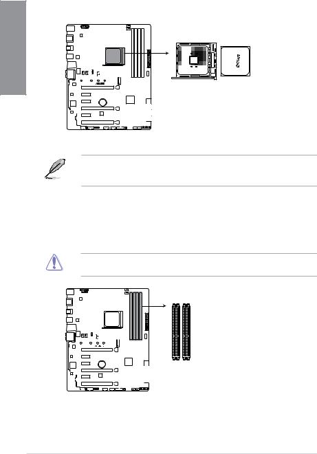
1.1.3Central Processing Unit (CPU)
The motherboard comes with a AM4 socket for AMD Ryzen™ /7th Generation A-series / Athlon™ Processors.
1 Chapter
PRIME X370-PRO
PRIME X370-PRO CPU socket AM4
The AM4 socket has a different pinout from the AM3+/FM2+/FM2 socket. Ensure that you use a CPU designed for the AM4 socket. The CPU fits in only one correct orientation. DO NOT force the CPU into the socket to prevent bending the pins and damaging the CPU!
1.1.4System memory
The motherboard comes with four DDR4 (Double Data Rate 4) Quad Inline Memory Modules (DIMM) slots.
A DDR4 module is notched differently from a DDR, DDR2, or DDR3 module. DO NOT install a DDR, DDR2, or DDR3 memory module to the DDR4 slot.
DIMM_A1 DIMM_A2
DIMM_B1 DIMM_B2
PRIME X370-PRO
PRIME X370-PRO 288-pin DDR4 DIMM sockets
1-4 |
Chapter 1: Product Introduction |
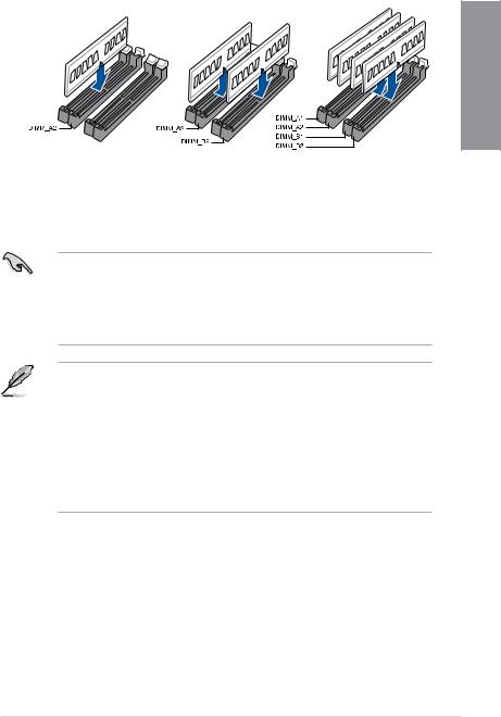
Recommended memory configurations
Chapter 1
Memory configurations
You may install 1 GB, 2 GB, 4 GB, 8 GB and 16 GB unbuffered ECC and non ECC DDR4 DIMMs into the DIMM sockets.
•You may install varying memory sizes in Channel A and Channel B. The system maps the total size of the lower-sized channel for the dual-channel configuration. Any excess memory from the higher-sized channel is then mapped for single-channel operation.
•This motherboard does not support DIMMs made up of 512 Mb (64 MB) chips or less (Memory chip capacity counts in Megabit, 8 Megabit/Mb = 1 Megabyte/MB).
•The default memory operation frequency is dependent on its Serial Presence Detect (SPD), which is the standard way of accessing information from a memory module. Under the default state, some memory modules for overclocking may operate at a lower frequency than the vendor-marked value.
•For system stability, use a more efficient memory cooling system to support a full memory load (4 DIMMs) or overclocking condition.
•Always install the DIMMS with the same CAS Latency. For an optimum compatibility, we recommend that you install memory modules of the same version or data code (D/C) from the same vendor. Check with the vendor to get the correct memory modules.
ASUS PRIME X370-PRO |
1-5 |

1.1.5Expansion slots
Unplug the power cord before adding or removing expansion cards. Failure to do so may cause you physical injury and damage motherboard components.
1 Chapter
PCIEX16_1
PRIME X370-PRO
 PCIEX1_1
 PCIEX1_2
BATTERY
PCIEX16_2
 PCIEX1_3
PCIEX16_3
Slot No. Slot Description
1PCIE 3.0/2.0 x16_1 slot
2PCIE 2.0 x1_1 slot
3PCIE 2.0 x1_2 slot
4 PCIE 3.0/2.0 x16_2 slot
5PCIE 2.0 x1_3 slot
6PCIE 2.0 x16_3 slot
|
PCI Express 3.0 operating mode |
||
VGA configuration |
|
|
|
PCIe 3.0/2.0 x16_1 |
PCIe 3.0/2.0 x16_2 |
||
|
|||
|
|
|
|
Single VGA/PCIe card |
x16 (single VGA |
N/A |
|
recommended) |
|||
|
|
||
|
|
|
|
Dual VGA/PCIe card |
x8 |
x8 |
|
|
|
|
|
1-6 |
Chapter 1: Product Introduction |
•Due to CPU limitation, PCIe 3.0/2.0 x16_1 working at @x16 or x8 varies by processor
when using one graphics card.
•We recommend that you provide sufficient power when running CrossFireX™ or SLI® mode.
•Connect chassis fans to the motherboard chassis fan connectors when using multiple graphics cards for better thermal environment.
IRQ assignments for this motherboard
For AMD 7th Generation A-series/Athlon™ Processors
|
A |
B |
C |
D |
E |
F |
G |
H |
|
PCIe x16_1 |
- |
- |
- |
shared |
- |
- |
- |
- |
|
PCIe x16_2 |
shared |
- |
- |
- |
- |
- |
- |
- |
|
PCIe x16_3 |
- |
shared |
- |
- |
- |
- |
- |
- |
|
PCIe x1_1 |
- |
- |
shared |
- |
- |
- |
- |
- |
|
PCIe x1_2 |
- |
- |
- |
shared |
- |
- |
- |
- |
|
PCIe x1_3 |
- |
- |
- |
shared |
- |
- |
- |
- |
|
M.2 |
- |
- |
- |
shared |
- |
- |
- |
- |
|
CPU USB3.0 XHCI |
- |
- |
shared |
- |
- |
- |
- |
- |
|
Controller |
|||||||||
|
|
|
|
|
|
|
|
||
|
|
|
|
|
|
|
|
|
|
AMD Chipset XHCI |
shared |
- |
- |
- |
- |
- |
- |
- |
|
Controller |
|||||||||
|
|
|
|
|
|
|
|
||
SATA Controller |
- |
- |
- |
shared |
- |
- |
- |
- |
|
HD Audio Controller |
- |
- |
- |
- |
- |
- |
shared |
- |
|
Intel LAN |
- |
- |
shared |
- |
- |
- |
- |
- |
|
ASMedia Connector |
shared |
- |
- |
- |
- |
- |
- |
- |
For AMD Ryzen™ Processors
|
A |
B |
C |
D |
E |
F |
G |
H |
|
PCIe x16_1 |
- |
- |
- |
- |
- |
- |
shared |
- |
|
PCIe x16_2 |
shared |
- |
- |
- |
- |
- |
- |
- |
|
PCIe x16_3 |
- |
shared |
- |
- |
- |
- |
- |
- |
|
PCIe x1_1 |
- |
- |
shared |
- |
- |
- |
- |
- |
|
PCIe x1_2 |
- |
- |
- |
shared |
- |
- |
- |
- |
|
PCIe x1_3 |
- |
- |
- |
shared |
- |
- |
- |
- |
|
M.2 |
shared |
- |
- |
- |
- |
- |
- |
- |
|
CPU USB3.0 XHCI |
- |
- |
- |
- |
- |
- |
- |
shared |
|
Controller |
|||||||||
|
|
|
|
|
|
|
|
||
|
|
|
|
|
|
|
|
|
|
AMD Chipset XHCI |
shared |
- |
- |
- |
- |
- |
- |
- |
|
Controller |
|||||||||
|
|
|
|
|
|
|
|
||
SATA Controller |
- |
shared |
- |
- |
- |
- |
- |
- |
|
HD Audio Controller |
- |
- |
- |
shared |
- |
- |
- |
- |
|
Intel LAN |
- |
- |
shared |
- |
- |
- |
- |
- |
|
ASMedia Connector |
shared |
- |
- |
- |
- |
- |
- |
- |
Chapter 1
ASUS PRIME X370-PRO |
1-7 |
1.1.6Jumpers and Headers
|
1. Clear RTC RAM jumper (2-pin CLRTC) |
||||||||||||||||||||||||||||
|
This jumper allows you to clear the Real Time Clock (RTC) RAM in CMOS. You can |
||||||||||||||||||||||||||||
1Chapter |
clear the CMOS memory of date, time, and system setup parameters by erasing the |
||||||||||||||||||||||||||||
CMOS RTC RAM data. The onboard button cell battery powers the RAM data in |
|||||||||||||||||||||||||||||
|
|||||||||||||||||||||||||||||
|
CMOS, which include system setup information such as system passwords. |
||||||||||||||||||||||||||||
|
|
|
|
|
|
|
|
|
|
|
|
|
|
|
|
|
|
|
|
|
|
|
|
|
|
|
|
|
|
|
|
|
|
|
|
|
|
|
|
|
|
|
|
|
|
|
|
|
|
|
|
|
|
|
|
|
|
|
|
|
|
|
|
|
|
|
|
|
|
|
|
|
|
|
|
|
|
|
|
|
|
|
|
|
|
|
|
|
|
|
|
|
|
|
|
|
|
|
|
|
|
|
|
|
|
|
|
|
|
|
|
|
|
|
|
|
|
|
|
|
|
|
|
|
|
|
|
|
|
|
|
|
|
|
|
|
|
|
|
|
|
|
|
|
|
|
|
|
|
|
|
|
|
|
|
|
|
|
|
|
|
|
|
|
|
|
|
|
|
|
|
|
|
|
|
|
|
|
|
|
|
|
|
|
|
|
|
|
|
|
|
|
|
|
|
|
|
|
|
|
|
|
|
|
|
|
|
|
|
|
|
|
|
|
|
|
|
|
|
|
|
|
|
|
|
|
|
|
|
|
|
|
|
|
|
|
|
|
|
|
|
|
|
|
|
|
|
|
|
|
|
|
|
|
|
|
|
|
|
|
|
|
|
|
|
|
|
|
|
|
|
|
|
|
|
|
|
|
|
|
|
|
|
|
|
|
|
|
|
|
|
|
|
|
|
|
|
|
|
|
|
|
|
|
|
|
|
|
|
|
|
|
|
|
|
|
|
|
|
|
|
|
|
|
|
|
|
|
|
|
|
|
|
|
|
|
|
|
|
|
|
|
|
|
|
|
|
|
|
|
|
|
|
|
|
|
|
|
|
|
|
|
|
|
|
|
|
|
|
|
|
|
|
|
|
|
|
|
|
|
|
|
|
|
|
|
|
|
|
|
|
|
|
|
|
|
|
|
|
|
|
|
|
|
|
|
|
|
|
|
|
|
|
|
|
|
|
|
|
|
|
|
|
|
|
|
|
|
|
|
|
|
|
|
|
|
|
|
|
|
|
|
|
|
|
|
|
|
|
|
|
|
|
|
|
|
|
|
|
|
|
|
|
|
|
|
|
|
|
|
|
|
|
|
|
|
|
|
|
|
|
|
|
|
|
|
|
|
|
|
|
|
|
|
|
|
|
|
|
|
|
|
|
|
|
|
|
|
|
|
|
|
|
|
|
|
|
|
|
|
|
|
|
|
|
|
|
|
|
|
|
|
|
|
|
|
|
|
|
|
|
|
|
|
|
|
|
|
|
|
|
|
|
|
|
|
|
|
|
|
|
|
|
|
|
|
|
|
|
|
|
|
|
|
|
|
|
|
|
|
|
|
|
|
|
|
|
|
|
|
|
|
|
|
|
|
|
|
|
|
|
|
|
|
|
|
|
|
|
|
|
|
|
|
|
|
|
|
|
|
|
|
|
|
|
|
|
|
|
|
|
|
|
|
|
|
|
|
|
|
|
|
|
|
|
|
|
|
|
|
|
|
|
|
|
|
|
|
|
|
|
|
|
|
|
|
|
|
|
|
|
|
|
|
|
|
|
|
|
|
|
|
|
|
|
|
|
|
|
PRIME X370-PRO |
CLRTC |
|
VDD RTC GND |
PIN 1
PRIME X370-PRO Clear RTC RAM
To erase the RTC RAM:
1.Turn OFF the computer and unplug the power cord.
2.Short-circuit pin 1-2 with a metal object or jumper cap for about 5-10 seconds.
3.Plug the power cord and turn ON the computer.
4.Hold down the <Delete> key during the boot process and enter BIOS setup to re-enter data.
Except when clearing the RTC RAM, never place a metal object or jumper cap on the
CLRTC jumper. Placing a metal object or jumper cap will cause system boot failure!
•If the steps above do not help, remove the onboard battery and place a metal object or jumper cap again to clear the CMOS RTC RAM data. After the CMOS clearance, reinstall the battery.
•You do not need to clear the RTC when the system hangs due to overclocking. For system failure due to overclocking, use the C.P.R. (CPU Parameter Recall) feature. Shut down and reboot the system so the BIOS can automatically reset parameter settings to default values.
•Due to the chipset behavior, AC power off is required to enable C.P.R. function. You must turn off and turn on the power supply or unplug and plug the power cord before
rebooting the system.
1-8 |
Chapter 1: Product Introduction |
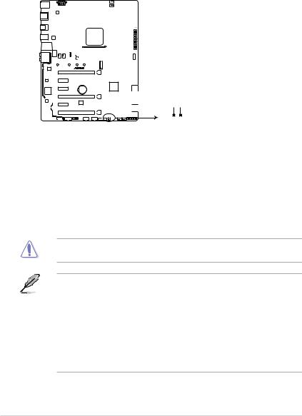
2.RGB Header (4-pin RGB_HEADER)
This connector is for RGB LED strips.
RGB_HEADER
 B
B
R
 G
G  +12V
+12V
PIN 1
PRIME X370-PRO
PRIME X370-PRO RGB_HEADER connector
The RGB header supports 5050 RGB multi-color LED strips (12V/G/R/B), with a maximum power rating of 2A (12V), and no longer than 2 m.
Before you install or remove any component, ensure that the ATX power supply is switched off or the power cord is detached from the power supply. Failure to do so may cause severe damage to the motherboard, peripherals, or components.
• Actual lighting and color will vary with LED strip.
• If your LED strip does not light up, check if the RGB LED extension cable and the RGB LED strip is connected in the correct orientation, and the 12V connector is aligned with the 12V header on the motherboard.
•The LED strip will only light up under the operating system.
•The LED strip is purchased separately.
Chapter 1
ASUS PRIME X370-PRO |
1-9 |
1.1.7Internal connectors
|
1. |
Serial ATA 6 Gb/s connectors (7-pin SATA6G_12; SATA 6G_34; |
|||||||||||||||||||||||||||||||||||
|
|||||||||||||||||||||||||||||||||||||
|
|
SATA 6G_56; SATA 6G_78) |
|
|
|
||||||||||||||||||||||||||||||||
1Chapter |
|
These connectors connect to Serial ATA 6 Gb/s hard disk drives via Serial ATA 6 Gb/s |
|||||||||||||||||||||||||||||||||||
|
signal cables. |
|
|
|
|||||||||||||||||||||||||||||||||
|
|
|
|
|
|||||||||||||||||||||||||||||||||
|
|
If you installed Serial ATA hard disk drives, you can create a RAID 0, 1, and 10 |
|||||||||||||||||||||||||||||||||||
|
|
configuration through the onboard AMD X370 chipset. |
|||||||||||||||||||||||||||||||||||
|
|
|
|
|
|
|
|
|
|
|
|
|
|
|
|
|
|
|
|
|
|
|
|
|
|
|
|
|
|
|
|
SATA6G_7 |
SATA6G_8 |
||||
|
|
|
|
|
|
|
|
|
|
|
|
|
|
|
|
|
|
|
|
|
|
|
|
|
|
|
|
|
|
|
|
|
|
||||
|
|
|
|
|
|
|
|
|
|
|
|
|
|
|
|
|
|
|
|
|
|
|
|
|
|
|
|
|
|
|
|
GND |
|
|
GND |
|
|
|
|
|
|
|
|
|
|
|
|
|
|
|
|
|
|
|
|
|
|
|
|
|
|
|
|
|
|
|
|
|
|
RSATA_TXP7 |
|
|
RSATA_TXP8 |
|
|
|
|
|
|
|
|
|
|
|
|
|
|
|
|
|
|
|
|
|
|
|
|
|
|
|
|
|
|
|
|
|
|
RSATA_TXN7 |
|
|
RSATA_TXN8 |
|
|
|
|
|
|
|
|
|
|
|
|
|
|
|
|
|
|
|
|
|
|
|
|
|
|
|
|
|
|
|
|
|
|
GND |
|
|
GND |
|
|
|
|
|
|
|
|
|
|
|
|
|
|
|
|
|
|
|
|
|
|
|
|
|
|
|
|
|
|
|
|
|
|
RSATA_RXN7 |
|
|
RSATA_RXN8 |
|
|
|
|
|
|
|
|
|
|
|
|
|
|
|
|
|
|
|
|
|
|
|
|
|
|
|
|
|
|
|
|
|
|
RSATA_RXP7 |
|
|
RSATA_RXP8 |
|
|
|
|
|
|
|
|
|
|
|
|
|
|
|
|
|
|
|
|
|
|
|
|
|
|
|
|
|
|
|
|
|
|
GND |
|
|
GND |
|
|
|
|
|
|
|
|
|
|
|
|
|
|
|
|
|
|
|
|
|
|
|
|
|
|
|
|
|
|
|
|
|
|
SATA6G_5 |
SATA6G_6 |
||||
|
|
|
|
|
|
|
|
|
|
|
|
|
|
|
|
|
|
|
|
|
|
|
|
|
|
|
|
|
|
|
|
||||||
|
|
|
|
|
|
|
|
|
|
|
|
|
|
|
|
|
|
|
|
|
|
|
|
|
|
|
|
|
|
|
|
GND |
|
|
GND |
|
|
|
|
|
|
|
|
|
|
|
|
|
|
|
|
|
|
|
|
|
|
|
|
|
|
|
|
|
|
|
|
|
|
RSATA_TXP5 |
|
|
RSATA_TXP6 |
|
|
|
|
|
|
|
|
|
|
|
|
|
|
|
|
|
|
|
|
|
|
|
|
|
|
|
|
|
|
|
|
|
|
RSATA_TXN5 |
|
|
RSATA_TXN6 |
|
|
|
|
|
|
|
|
|
|
|
|
|
|
|
|
|
|
|
|
|
|
|
|
|
|
|
|
|
|
|
|
|
|
GND |
|
|
GND |
|
|
|
|
|
|
|
|
|
|
|
|
|
|
|
|
|
|
|
|
|
|
|
|
|
|
|
|
|
|
|
|
|
|
|
|
||||
|
|
|
|
|
|
|
|
|
|
|
|
|
|
|
|
|
|
|
|
|
|
|
|
|
|
|
|
|
|
|
|
RSATA_RXN5 |
|
|
RSATA_RXN6 |
|
|
|
|
|
|
|
|
|
|
|
|
|
|
|
|
|
|
|
|
|
|
|
|
|
|
|
|
|
|
|
|
|
|
RSATA_RXP5 |
|
|
RSATA_RXP6 |
|
|
|
|
|
|
|
|
|
|
|
|
|
|
|
|
|
|
|
|
|
|
|
|
|
|
|
|
|
|
|
|
|
|
GND |
|
|
GND |
|
|
|
|
|
|
|
|
|
|
|
|
|
|
|
|
|
|
|
|
|
|
|
|
|
|
|
|
|
|
|
|
|
|
SATA6G_3 |
SATA6G_4 |
||||
|
|
|
|
|
|
|
|
|
|
|
|
|
|
|
|
|
|
|
|
|
|
|
|
|
|
|
|
|
|
|
|
||||||
|
|
|
|
|
|
|
|
|
|
|
|
|
|
|
|
|
|
|
|
|
|
|
|
|
|
|
|
|
|
||||||||
|
|
|
|
|
|
|
|
|
|
|
|
|
|
|
|
|
|
|
|
|
|
|
|
|
|
|
|
|
|
|
|
GND |
|
|
GND |
|
|
|
|
|
|
|
|
|
|
|
|
|
|
|
|
|
|
|
|
|
|
|
|
|
|
|
|
|
|
|
|
|
|
RSATA_TXP3 |
|
|
RSATA_TXP4 |
|
|
|
|
|
|
|
|
|
|
|
|
|
|
|
|
|
|
|
|
|
|
|
|
|
|
|
|
|
|
|
|
|
|
|
|
|
|
||
|
|
|
|
|
|
|
|
|
|
|
|
|
|
|
|
|
|
|
|
|
|
|
|
|
|
|
|
|
|
|
|
RSATA_TXN3 |
|
|
RSATA_TXN4 |
|
|
|
|
|
|
|
|
|
|
|
|
|
|
|
|
|
|
|
|
|
|
|
|
|
|
|
|
|
|
|
|
|
|
GND |
|
|
GND |
|
|
|
|
|
|
|
|
|
|
|
|
|
|
|
|
|
|
|
|
|
|
|
|
|
|
|
|
|
|
|
|
|
|
|
|
||||
|
|
|
|
|
|
|
|
|
|
|
|
|
|
|
|
|
|
|
|
|
|
|
|
|
|
|
|
|
|
|
|
RSATA_RXN3 |
|
|
RSATA_RXN4 |
|
|
|
|
|
|
|
|
|
|
|
|
|
|
|
|
|
|
|
|
|
|
|
|
|
|
|
|
|
|
|
|
|
|
RSATA_RXP3 |
|
|
RSATA_RXP4 |
|
|
|
|
|
|
|
|
|
|
|
|
|
|
|
|
|
|
|
|
|
|
|
|
|
|
|
|
|
|
|
|
|
|
GND |
|
|
GND |
|
|
|
|
|
|
|
|
|
|
|
|
|
|
PRIME X370-PRO |
|
|
|
|
|
||||||||||||||||||||
|
|
|
|
|
|
|
|
|
|
|
|
|
|
|
|
|
|
|
|
|
|
|
|
|
|
|
|
|
|
|
|
SATA6G_1 |
SATA6G_2 |
||||
|
|
|
|
|
|
|
|
|
|
|
|
|
|
|
|
|
|
|
|
|
|
|
|
|
|
|
|
|
|
||||||||
|
|
|
|
|
|
|
|
|
|
|
|
|
|
|
|
|
|
|
|
|
|
|
|
|
|
|
|
|
|
||||||||
|
|
|
|
|
|
|
|
|
|
|
|
|
|
|
|
|
|
|
|
|
|
|
|
|
|
|
|
|
|
|
|
GND |
|
|
GND |
|
|
|
|
|
|
|
|
|
|
|
|
|
|
|
|
|
|
|
|
|
|
|
|
|
|
|
|
|
|
|
|
|
|
RSATA_TXP1 |
|
|
RSATA_TXP2 |
|
|
|
|
|
|
|
|
|
|
|
|
|
|
|
|
|
|
|
|
|
|
|
|
|
|
|
|
|
|
|
|
|
|
RSATA_TXN1 |
|
|
RSATA_TXN2 |
|
|
|
|
|
|
|
|
|
|
|
|
|
|
|
|
|
|
|
|
|
|
|
|
|
|
|
|
|
|
|
|
|
|
GND |
|
|
GND |
|
|
|
|
|
|
|
|
|
|
|
|
|
|
|
|
|
|
|
|
|
|
|
|
|
|
|
|
|
|
|
|
|
|
RSATA_RXN1 |
|
|
RSATA_RXN2 |
|
|
|
|
|
|
|
|
|
|
|
|
|
|
|
|
|
|
|
|
|
|
|
|
|
|
|
|
|
|
|
|
|
|
RSATA_RXP1 |
|
|
RSATA_RXP2 |
|
|
|
|
|
|
|
|
|
|
|
|
|
|
|
|
|
|
|
|
|
|
|
|
|
|
|
|
|
|
|
|
|
|
|
|
||||
|
|
|
|
|
|
|
|
|
|
|
|
|
|
|
|
|
|
|
|
|
|
|
|
|
|
|
|
|
|
|
|
GND |
|
|
GND |
|
|
|
|
|
|
|
|
|
|
|
|
|
|
|
|
|
|
|
|
|
|
|
|
|
|
|
|
|
|
|
|
|
|
|
|
|
|
|
|
|
|
|
|
|
|
|
|
|
|
|
|
|
|
|
|
|
|
|
|
|
|
|
|
|
|
|
|
|
|
|
|
|
|
|
|
|
|
PRIME X370-PRO SATA 6.0Gb/s connectors
These connectors are set to [AHCI Mode] by default. If you intend to create a Serial ATA
RAID set using these connectors, set the SATA Mode item in the BIOS to (RAID)].
1-10 |
Chapter 1: Product Introduction |
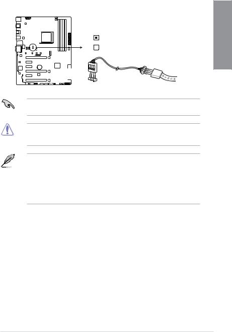
2.Front panel audio connector (10-1 pin AAFP)
This connector is for a chassis-mounted front panel audio I/O module that supports HD Audio. Connect one end of the front panel audio I/O module cable to this connector.
|
AGND NC SENSE1 RETUR |
SENSE2 RETUR |
|
AAFP |
|
PRIME X370-PRO |
PORT1 L PORT1 R PORT2 R |
SENSE SEND PORT2 L |
|
||
|
HD-audio-compliant |
|
|
pin definition |
|
PRIME X370-PRO Front panel audio connector
We recommend that you connect a high-definition front panel audio module to this connector to avail of the motherboard’s high-definition audio capability.
3.USB 2.0 connectors (10-1 pin USB12; USB34)
These connectors are for USB 2.0 ports. Connect the USB module cable to these connectors, then install the module to a slot opening at the back of the system chassis. This USB connector complies with USB 2.0 specification that supports up to 480 Mb/s connection speed.
Chapter 1
|
|
USB34 |
|
PRIME X370-PRO |
|
USB+5V USB P3USB P3+ |
GND NC |
|
PIN 1 |
USB+5V USB P4USB P4+ |
GND |
|
|
||
PRIME X370-PRO USB2.0 connectors
USB12
|
|
USB+5V USB_P1USB_P1+ |
GND NC |
||||
|
|
|
|
|
|
|
|
|
|
|
|
|
|
|
|
|
|
|
|
|
|
|
|
|
|
|
|
|
|
|
|
PIN 1 |
USB+5V USB P2USB P2+ |
GND |
|||||
|
|
||||||
DO NOT connect a 1394 cable to the USB connectors. Doing so will damage the motherboard!
The USB 2.0 module is purchased separately.
ASUS PRIME X370-PRO |
1-11 |
1 Chapter
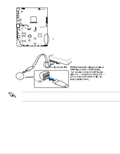
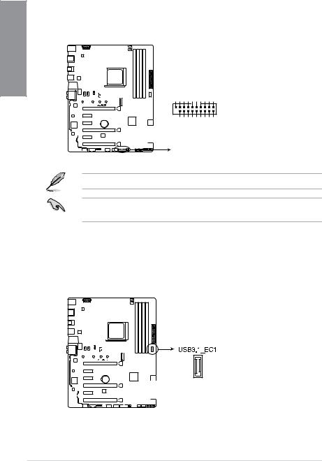
4.USB 3.0 connector (20-1 pin USB3_12)
This connector allows you to connect a USB 3.0 module for additional USB 3.0 front or rear panel ports. With an installed USB 3.0 module, you can enjoy all the benefits of USB 3.0 including faster data transfer speeds of up to 5 Gb/s, faster charging time for USB-chargeable devices, optimized power efficiency, and backward compatibility with USB 2.0.
USB3_12
P1_IntA P1_IntAGNDP1_IntA P1_IntAGNDP1_IntA P1_IntAGND USB3+5V____D__ SSRXSSTX-D+ -SSRX+-SSTX+
PIN 1
PRIME X370-PRO
_IntA_IntA _IntA_IntA _P2_P2 _P2_P2 P2_IntA P2_IntA SSRXSSTXD__ USB3+5V-SSRX+GND-SSTX+GND-D+
PRIME X370-PRO USB3.0 Front panel connector
The USB 3.0 module is purchased separately.
The plugged USB 3.0 device may run on xHCI mode depending on the operating system’s setting.
5.USB 3.1 connector (20-pin USB3.1_C1)
This connector allows you to connect a USB 3.1 module for additional USB 3.1 front or rear panel ports. The latest USB3.1 connectivity provides data transfer speeds of up to 10 Gbps. The next-generation standard is completely backward-compatible with your existing USB devices.
PRIME X370-PRO
PRIME X370-PRO USB3.1_EC1
1-12 |
Chapter 1: Product Introduction |
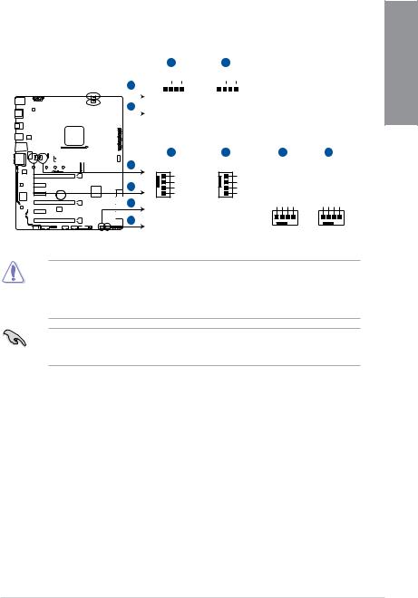
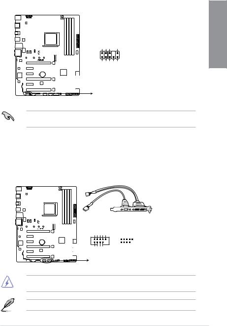
6.CPU, CPU optional, AIO pump, W_Pump, and chassis fan connectors (4-pin CPU_FAN; 4-pin CPU_OPT; 4-pin AIO_PUMP; 4-pin W_PUMP+; 4-pin CHA_FAN1- 2)
Connect the fan cables to the fan connectors on the motherboard, ensuring that the black wire of each cable matches the ground pin of the connector.
|
|
|
|
|
|
|
|
|
|
|
|
|
|
|
|
|
|
|
|
|
|
|
|
|
|
|
|
|
|
|
|
|
A |
|
|
|
|
|
|
B |
|
|
||||||||||||||||||||||
|
|
|
|
|
|
|
|
|
|
|
|
|
|
|
|
|
|
|
|
|
|
|
|
|
|
|
CPU_FAN |
CPU_OPT |
|
|
||||||||||||||||||||||||||||||||||
|
|
|
|
|
|
|
|
|
|
|
|
|
|
|
|
|
|
|
|
|
|
|
|
|
|
A |
|
|
|
|
|
|
|
|
|
|
|
|
|
|
|
|
|
|
|
|
|
|
|
|
|
|
|
|
|
|
|
|
|
|
|
|
|
|
|
|
|
|
|
|
|
|
|
|
|
|
|
|
|
|
|
|
|
|
|
|
|
|
|
|
B |
|
|
PWMFANCPU INFANCPU PWRFANCPU GND |
|
|
PWMFANCPU INFANCPU PWRFANCPU GND |
|
|
||||||||||||||||||||||||||||||
|
|
|
|
|
|
|
|
|
|
|
|
|
|
|
|
|
|
|
|
|
|
|
|
|
|
|
|
|
|
|
|
C |
|
|
|
|
|
|
D |
E |
F |
|||||||||||||||||||||||
|
|
|
|
|
|
|
|
|
|
|
|
|
|
|
|
|
|
|
|
|
|
|
|
|
|
|
|
|
|
|
|
|
|
|
|
|
|
|
||||||||||||||||||||||||||
|
|
|
|
|
|
|
|
|
|
|
|
|
|
|
|
|
|
|
|
|
|
|
|
|
|
|
|
|
|
|
|
|
|
|
|
|
|
|
||||||||||||||||||||||||||
|
|
|
|
|
|
|
|
|
|
|
|
|
|
|
|
|
|
|
|
|
|
|
|
|
|
|
|
|
|
|
|
|
|
|
|
|
|
|
||||||||||||||||||||||||||
|
|
|
|
|
|
|
|
|
|
|
|
|
|
|
|
|
|
|
|
|
|
|
|
|
|
|
|
|
|
|
|
|
|
|
|
|
|
|
||||||||||||||||||||||||||
|
|
|
|
|
|
|
|
|
|
|
|
|
|
|
|
|
|
|
|
|
|
|
|
|
|
|
|
|
|
|
|
|
|
|
|
|
|
|
||||||||||||||||||||||||||
|
|
|
|
|
|
|
|
|
|
|
|
|
|
|
|
|
|
|
|
|
|
|
|
|
|
|
|
|
|
|
|
|
|
|
|
|
|
|
||||||||||||||||||||||||||
|
|
|
|
|
|
|
|
|
|
|
|
|
|
|
|
|
|
|
|
|
|
|
|
|
|
|
|
|
|
|
|
|
|
|
|
|
|
|
||||||||||||||||||||||||||
|
|
|
|
|
|
|
|
|
|
|
|
|
|
|
|
|
|
|
|
|
|
|
|
|
|
|
|
|
|
|
|
|
|
|
|
|
|
|
||||||||||||||||||||||||||
|
|
|
|
|
|
|
|
|
|
|
|
|
|
|
|
|
|
|
|
|
|
|
|
|
|
|
|
|
|
|
|
|
|
|
|
|
|
|
||||||||||||||||||||||||||
|
|
|
|
|
|
|
|
|
|
|
|
|
|
|
|
|
|
|
|
|
|
|
|
|
|
|
||||||||||||||||||||||||||||||||||||||
|
|
|
|
|
|
|
|
|
|
|
|
|
|
|
|
|
|
|
|
|
|
|
|
|
|
|
||||||||||||||||||||||||||||||||||||||
|
|
|
|
|
|
|
|
|
|
|
|
|
|
|
|
|
|
|
|
|
|
|
|
|
|
C |
AIO_PUMP |
CHA_FAN1 |
CHA_FAN2 |
W_PUMP+ |
||||||||||||||||||||||||||||||||||
|
|
|
|
|
|
|
|
|
|
|
|
|
|
|
|
|
|
|
|
|
|
|
|
|
|
|||||||||||||||||||||||||||||||||||||||
PRIME X370-PRO |
GND |
GND |
CHAFAN IN CHAFANPWM |
GND PUMP+W PWR PUMP+W IN PUMPW PWM |
AIO PUMP PWR |
CHA FAN PWR |
|||
E |
AIO PUMP IN |
GND CHAFANPWR |
||
D |
CHA FAN IN |
|
|
|
|
AIO PUMP PWM |
CHA FAN PWM |
|
|
F |
|
|
|
|
PRIME X370-PRO Fan connectors
•DO NOT forget to connect the fan cables to the fan connectors. Insufficient air flow inside the system may damage the motherboard components. These are not jumpers! Do not place jumper caps on the fan connectors!
•Ensure that the CPU fan cable is securely installed to the CPU fan connector.
•The CPU_FAN connector supports the CPU fan of maximum 1A (12 W) fan power.
•Connect the fan of your water cooling kit to the AIO_PUMP / W_PUMP+ connector.
Chapter 1
ASUS PRIME X370-PRO |
1-13 |
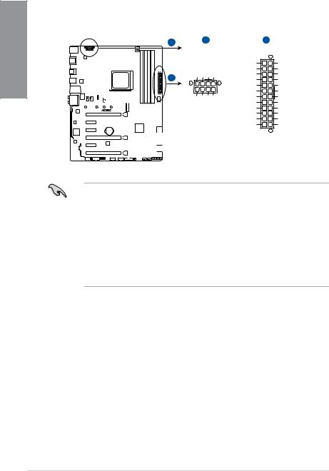
1 Chapter
7.ATX power connectors (24-pin EATXPWR; 8-pin EATX12V)
These connectors are for ATX power supply plugs. The power supply plugs are designed to fit these connectors in only one orientation. Find the proper orientation and push down firmly until the connectors completely fit.
A
B
PRIME X370-PRO
A |
|
|
B |
|
EATX12V |
|
EATXPWR |
||
DC DC DC DC |
+3 Volts |
GND |
||
+12V +12V +12V +12V |
+12 |
Volts |
+5 Volts |
|
+12 |
Volts |
+5 Volts |
||
|
+5V Standby |
+5 Volts |
||
|
Power OK |
-5 Volts |
||
PIN 1 |
|
GND |
GND |
|
+5 Volts |
GND |
|||
GND GND GND GND |
||||
|
GND |
GND |
||
+5 Volts |
PSON# |
|||
|
||||
|
|
GND |
GND |
|
|
+3 |
Volts |
-12 Volts |
|
|
+3 |
Volts |
+3 Volts |
|
|
|
PIN 1 |
|
|
PRIME X370-PRO ATX power connectors
•For a fully configured system, we recommend that you use a power supply unit (PSU) that complies with ATX 12 V Specification 2.0 (or later version) and provides a minimum power of 350 W.
•DO NOT forget to connect the 8-pin EATX12V power plug. Otherwise, the system will not boot.
•We recommend that you use a PSU with a higher power output when configuring a system with more power-consuming devices. The system may become unstable or may not boot up if the power is inadequate.
•If you want to use two or more high-end PCI Express x16 cards, use a PSU with 1000W power or above to ensure the system stability.
1-14 |
Chapter 1: Product Introduction |
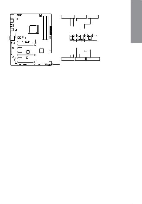
8.System panel connector (20-5 pin PANEL)
This connector supports several chassis-mounted functions.
|
PANEL |
|
|
+PWR_LEDPWR_SW SPEAKER |
|||
PLED+ PLEDPWRBTN# GND |
+5V GND GND Speaker |
||
PIN 1 |
GND RSTCON# NC PLED+ |
PLED- |
|
HDDLED+ HDDLED- |
|||
PRIME X370-PRO |
|
|
|
+HDD_LED- |
RESET |
+PWR_LED- |
|
* Requires an ATX power supply
PRIME X370-PRO System panel connector
•System power LED (4-pin +PWR_LED-)
This 2-pin connector is for the system power LED. Connect the chassis power LED cable to this connector. The system power LED lights up when you turn on the system power, and blinks when the system is in sleep mode.
•Hard disk drive activity LED (2-pin +HDD_LED-)
This 2-pin connector is for the HDD Activity LED. Connect the HDD Activity LED cable to this connector. The HDD LED lights up or flashes when data is read from or written to the HDD.
•System warning speaker (4-pin SPEAKER)
This 4-pin connector is for the chassis-mounted system warning speaker. The speaker allows you to hear system beeps and warnings.
•ATX power button/soft-off button (2-pin PWR_SW)
This connector is for the system power button. Pressing the power button turns the system on or puts the system in sleep or soft-off mode depending on the operating system settings. Pressing the power switch for more than four seconds while the system is ON turns the system OFF.
•Reset button (2-pin RESET)
This 2-pin connector is for the chassis-mounted reset button for system reboot without turning off the system power.
Chapter 1
ASUS PRIME X370-PRO |
1-15 |
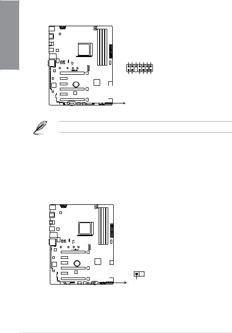
1 Chapter
9.TPM connector (14-1 pin TPM)
This connector supports a Trusted Platform Module (TPM) system, which securely stores keys, digital certificates, passwords and data. A TPM system also helps enhance network security, protect digital identities, and ensures platform integrity.
|
TPM |
|
|
F CLKRUN F SERIRQ F FRAME# F LAD3 F LAD2 F LAD1 F LAD0 |
|
|
|
PIN 1 |
PRIME X370-PRO |
+3VSB S PCIRST# TBD GND C PCICLK TPM |
+3V +3V |
|
||
PRIME X370-PRO TPM connector
The TPM module is purchased separately.
10.Thermal sensor connector (2-pin T_SENSOR)
This connector is for the thermistor cable that monitors the temperature of the devices and the critical components inside the motherboard. Connect the thermistor cable and place the sensor on the device or the motherboard’s component to detect its temperature.
PRIME X370-PRO
T_SENSOR
 GND
GND
PIN 1
SENSOR IN
PRIME X370-PRO T_SENSOR connector
1-16 |
Chapter 1: Product Introduction |
 Loading...