

Page 1
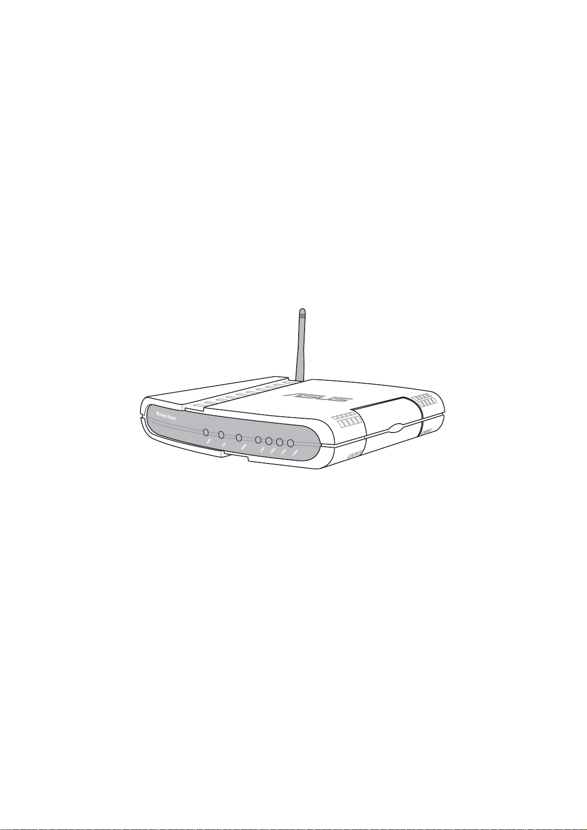
WL500g / WL500g Deluxe Wireless Router
(For 802.11g/b Wireless Clients)
WL500b Wireless Router
(For 802.11b Wireless Clients)
User’s Manual
Page 2

Copyright Information
No part of this manual, including the products and software described in it,
may be reproduced, transmitted, transcribed, stored in a retrieval system,
or translated into any language in any form or by any means, except
documentation kept by the purchaser for backup purposes, without the
express written permission of ASUSTeK COMPUTER INC. (“ASUS”).
ASUS PROVIDES THIS MANUAL “AS IS” WITHOUT WARRANTY
OF ANY KIND, EITHER EXPRESS OR IMPLIED, INCLUDING BUT
NOT LIMITED TO THE IMPLIED WARRANTIES OR CONDITIONS
OF MERCHANTABILITY OR FITNESS FOR A PARTICULAR
PURPOSE. IN NO EVENT SHALL ASUS, ITS DIRECT ORS, OFFICERS,
EMPLOYEES OR AGENTS BE LIABLE FOR ANY INDIRECT,
SPECIAL, INCIDENTAL, OR CONSEQUENTIAL DAMAGES
(INCLUDING DAMAGES FOR LOSS OF PROFITS, LOSS OF
BUSINESS, LOSS OF USE OR DAT A, INTERRUPTION OF BUSINESS
AND THE LIKE), EVEN IF ASUS HAS BEEN ADVISED OF THE
POSSIBILITY OF SUCH DAMAGES ARISING FROM ANY DEFECT
OR ERROR IN THIS MANUAL OR PRODUCT.
Product warranty or service will not be extended if: (1) the product is
repaired, modified or altered, unless such repair, modification of alteration
is authorized in writing by ASUS; or (2) the serial number of the product is
defaced or missing.
Products and corporate names appearing in this manual may or may not be
registered trademarks or copyrights of their respective companies, and are
used only for identification or explanation and to the owners’ benefit, without
intent to infringe.
SPECIFICATIONS AND INFORMATION CONTAINED IN THIS
MANUAL ARE FURNISHED FOR INFORMATIONAL USE ONL Y, AND
ARE SUBJECT T O CHANGE AT ANY TIME WITHOUT NOTICE, AND
SHOULD NOT BE CONSTRUED AS A COMMITMENT BY ASUS. ASUS
ASSUMES NO RESPONSIBILITY OR LIABILITY FOR ANY ERRORS
OR INACCURACIES THAT MAY APPEAR IN THIS MANUAL,
INCLUDING THE PRODUCTS AND SOFTWARE DESCRIBED IN IT.
Copyright © 2004 ASUSTeK COMPUTER INC. All Rights Reserved.
Product Name: WL500g/WL500g Deluxe/WL500b
Manual Revision: E1697
Release Date: July 2004
2 ASUS Wireless Router
Page 3

Contact Information
ASUSTeK COMPUTER INC. (Asia-Pacific)
Company Address: 15 Li-Te Road, Peitou, Taipei 112
General Telephone: +886-2-2894-3447
General Fax: +886-2-2894-7798
Web Site Address: www.asus.com.tw
General Email: info@asus.com.tw
Technical Support
MB/Others (Tel): +886-2-2890-7121
Notebook (Tel): +886-2-2894-3447
Desktop/Server (Tel): +886-2-2890-7123
Networking (Tel): +886-2-2890-7902
Support Fax: +886-2-2890-7698
ASUS COMPUTER INTERNATIONAL (America)
Company Address: 44370 Nobel Drive, Fremont, CA 94538, USA
General Fax: +1-510-608-4555
Web Site Address: usa.asus.com
General Email: tsd@asus.com
Technical Support
General Support: +1-502-995-0883
Notebook (Tel): +1-510-739-3777 x5110
Support Email: notebooktsd@asus.com
Support Fax: +1-502-933-8713
ASUS COMPUTER GmbH (Germany & Austria)
Company Address: Harkort Str. 25, D-40880 Ratingen, Germany
General Telephone: +49-2102-95990
General Fax: +49-2102-959911
Web Site Address: www.asuscom.de
Online Contact: www.asuscom.de/sales
Technical Support
Component Support: +49-2102-95990
Notebook Support: +49-2102-959910
Online Support: www.asuscom.de/support
Support Fax: +49-2102-959911
ASUS COMPUTER (Middle East and North Africa)
Company Address: P.O. Box 64133, Dubai, U.A.E.
General Telephone: +9714-283-1774
General Fax: +9714-283-1775
Web Site Address: www.ASUSarabia.com
ASUS Wireless Router 3
Page 4

Notices
Federal Communications Commission Statement
This device complies with Part 15 of the FCC Rules. Operation is subject to the
following two conditions:
• This device may not cause harmful interference, and
• This device must accept any interference received, including interference that may
cause undesired operation.
This equipment has been tested and found to comply with the limits for a class B
digital device, pursuant to Part 15 of the Federal Communications Commission (FCC)
rules. These limits are designed to provide reasonable protection against harmful
interference in a residential installation. This equipment generates, uses, and can
radiate radio frequency energy and, if not installed and used in accordance with the
instructions, may cause harmful interference to radio communications. However,
there is no guarantee that interference will not occur in a particular installation. If
this equipment does cause harmful interference to radio or television reception, which
can be determined by turning the equipment off and on, the user is encouraged to try
to correct the interference by one or more of the following measures:
• Reorient or relocate the receiving antenna.
• Increase the separation between the equipment and receiver .
• Connect the equipment into an outlet on a circuit different from that to which the
receiver is connected.
• Consult the dealer or an experienced radio/TV technician for help.
WARNING! The use of a shielded-type power cord is required in
order to meet FCC emission limits and to prevent interference to
the nearby radio and television reception. It is essential that only
the supplied power cord be used. Use only shielded cables to connect I/O devices to this equipment. Y ou are cautioned that changes
or modifications not expressly approved by the party responsible
for compliance could void your authority to operate the equipment.
Reprinted from the Code of Federal Regulations #47, part 15.193, 1993. W ashington
DC: Office of the Federal Register , National Archives and Records Administration,
U.S. Government Printing Office.
Canadian Department of Communications
This digital apparatus does not exceed the Class B limits for radio noise emissions
from digital apparatus set out in the Radio Interference Regulations of the Canadian
Department of Communications.
This Class B digital apparatus complies with Canadian ICES-003.
Cet appareil numérique de la classe B est conforme à la norme
NMB-003 du Canada.
4 ASUS Wireless Router
Page 5

Notices
FCC Radio Frequency Exposure Caution Statement
In order to maintain compliance with the FCC RF exposure guidelines,
this equipment should be installed and operated with minimum distance 20
cm between the radiator and your body. Use only with supplied antenna.
Unauthorized antenna, modification, or attachments could damage the
transmitter and may violate FCC regulations. Any changes of modifications
not expressly approved by the grantee of this device could void the users
authority to operate the equipment.
Installation and use of this W ireless LAN device must be in strict accordance
with the instructions included in the user documentation provided with the
product. Any changes or modifications (including the antennas) made to
this device that are not expressly approved by the manufacturer may void
the user’s authority to operate the equipment. The manufacturer is not
responsible for any radio or television interference caused by unauthorized
modification of this device, or the substitution or attachment of connecting
cables and equipment other than manufacturer specified. It is the
responsibility of the user to correct any interference caused by such
unauthorized modification, substitution or attachment. Manufacturer and
its authorized resellers or distributors will assume no liability for any damage
or violation of government regulations arising from failing to comply with
these guidelines.
ASUS Wireless Router 5
Page 6

Table of Contents
1. Introduction.......................................................................................... 9
Overview................................................................................................ 9
System Requirements ........................................................................... 9
Features .............................................................................................. 10
The Product Package ..................................................................... 10
The ASUS Wireless Family............................................................. 12
Network Topology ................................................................................ 14
Network Backbone.......................................................................... 14
Agent to an ISP............................................................................... 15
Agent to Another Network ............................................................... 16
LED Indicators ..................................................................................... 17
2. Installation Procedure....................................................................... 18
Wall Mounting Option .......................................................................... 20
Vertical Standing Option ...................................................................... 21
Connecting to the ASUS Wireless Router ........................................... 22
3. Software Configuration..................................................................... 23
Configuring the ASUS Wireless Router ............................................... 23
Setting IP address for Wired or Wireless Connection..................... 23
Installing the ASUS Wireless Router Utilities....................................... 25
Using the Wireless Router for the First Time....................................... 26
1. ASUS Wireless Router Utilities .................................................. 26
2. Connect to the ASUS WLAN Web Manager .............................. 26
3. Set your own password.............................................................. 28
4. Use Quick Setup ........................................................................ 28
Home Gateway Mode.......................................................................... 29
Wireless............................................................................................... 32
Interface .......................................................................................... 32
Bridge/Access Control List.............................................................. 37
Access Control................................................................................ 40
Radius Setting (WL500g/WL500g Deluxe) ..................................... 41
Advanced ........................................................................................ 42
IP Config.............................................................................................. 44
WAN & LAN .................................................................................... 44
DHCP Server .................................................................................. 47
DHCP Server (Cont.) ...................................................................... 48
6 ASUS Wireless Router
Page 7

Table of Contents
Static Route .................................................................................... 49
Miscellaneous ................................................................................. 50
NAT Setting ......................................................................................... 52
Port Trigger ..................................................................................... 52
Virtual Server .................................................................................. 53
Virtual DMZ ..................................................................................... 54
Internet Firewall ................................................................................... 55
Basic Config.................................................................................... 57
URL Filter ........................................................................................ 58
USB Application................................................................................... 59
FTP Server...................................................................................... 59
User Account List ............................................................................ 61
Banned IP List................................................................................. 63
Client Setting................................................................................... 63
Web Camera................................................................................... 64
Web Camera - Client Setting .......................................................... 66
Web Camera vs. DDNS .................................................................. 68
Security Mode Setting..................................................................... 68
Remote Monitor Setting .................................................................. 69
System Setup ...................................................................................... 70
Operation Mode .............................................................................. 70
Router Mode (WL500g/WL500g Deluxe)........................................ 71
Quick Setup in Router Mode........................................................... 71
AP Mode ......................................................................................... 72
Quick Setup in Access Point Mode ................................................. 72
Configure Wireless Interface........................................................... 72
IP Config (Access Point Mode) ....................................................... 73
LAN ................................................................................................. 73
Get IP Automatically........................................................................ 73
Change Password........................................................................... 74
Firmware Upgrade............................................................................... 75
Setting Management....................................................................... 76
Factory Default................................................................................ 77
Restoring Factory Default Settings ................................................. 77
Status & Log ........................................................................................ 78
Firmware Restoration .......................................................................... 80
Using a Hub .................................................................................... 80
ASUS Wireless Router 7
Page 8

Table of Contents
Setup Printer Wizard ........................................................................... 81
Installing the Printer Driver.............................................................. 81
Setup for LPR client under Windows XP ............................................. 84
Printer Setup Wizard....................................................................... 86
V erifying Your Printer ...................................................................... 87
4. Wireless Performance ...................................................................... 89
Site Topography................................................................................... 89
Site Surveys ........................................................................................ 89
Range .................................................................................................. 90
Troubleshooting..................................................................................... 91
Common Problems and Solutions ....................................................... 91
Reset to Defaults ................................................................................. 92
Glossary .............................................................................................. 95
Licensing Information .......................................................................... 98
Availability of source code .............................................................. 98
The GNU General Public License ....................................................... 99
8 ASUS Wireless Router
Page 9

1. Introduction
Overview
Chapter 1 - Introduction
Thank you for purchasing the ASUS Wireless Router. The ASUS Wireless
Router, WL500g/WL500g Deluxe, complies with IEEE 802.11g and
802.11b standards. The ASUS 802.1 1b W ireless Router , WL500b, complies
with IEEE 802.11b standards. The 802.11g is as extension to 802.1 1b (used
in majority of wireless LANs today) that broadens 802.11b’s data rates to
54 Mbps within the 2.4 GHz band using OFDM (orthogonal frequency
division multiplexing) technology. The 802.11g allows backward
compatibility with 802.11b devices but only at 1 1 Mbps or lower, depending
on the range and presence of obstructions. Wireless LANs are
complementary extensions to existing wired LANs, offering complete
mobility while maintaining continuous network connectivity to both
corporate and home Intranets. They add a new level of convenience for
LAN users. PC users stay connected to the network anywhere throughout a
building without being bound by a LAN wires. This is accomplished through
the use of Access Point functionality of ASUS Wireless Routers. ASUS
Wireless Router with built-in Internet gateway capability , allows your family
to share a broadband Modem and one ISP account simultaneously from
different rooms without wires! ASUS Wireless products can keep you
connected anywhere, any time.
1. Introduction
System Requirements
T o begin using the ASUS 802.1 1g/802.11b W ireless Router , you must have
the following minimum requirements:
• ADSL/Cable Modem and Broadband Internet Account.
• An Ethernet (10Base-T or 10/100Base-TX) adapter for wired client
• At least one 802.1 1g (54Mbps) or one 802.1 1b (1 1Mbps) wireless adapter
for wireless mobile clients
• TCP/IP and an Internet browser installed
ASUS Wireless Router 9
Page 10

Chapter 1 - Introduction
1. Introduction
The Product Package
The WL500g/WL500g Deluxe Wireless Router comes with:
• One ASUS 802.11g Wireless Router
• One ASUS Wireless Router Quick Start Guide
• One power adapter (5 Volts DC)
• One support CD (utilities and user’s manual)
• One RJ-45 Ethernet cable (straight-through)
The WL500b Wireless Router comes with:
• One ASUS 802.11b Wireless Router
• One ASUS Wireless Router Quick Start Guide
• One power adapter (5 Volts DC)
• One support CD (utilities and user’s manual)
• One RJ-45 Ethernet cable (straight-through)
Features
The WL500g/WL500g Deluxe and WL500b Wireless Router features
include:
• Wireless Connectivity And Protect Compatibility. WL500g/WL500g
Deluxe Wireless Router enables fastest 54Mbps IEEE 802.11g wireless
transmission but keeps compatibility with existing IEEE 802.11b devices.
WL500g Deluxe increases performance compared with standard 802.11g
when Afterburner mode is enabled. The WL-500b W ireless Router utilizes
the IEEE 802.11b standard.
• Secure wireless connectivity. The integrated Wireless Access Point with
WP A authentication and encryption functionality allows the wireless router
to link a broadband Internet connection to your local network of 802.11g
or/and 802.11b wireless mobile clients securely . The ASUS W ireless Router
is firmware upgradable to support WPA.
• Multiple local network ports. Four 10/100Base-T Ethernet ports, offering
either a connection to a hub or switch on the local wired network or a direct
connection to multiple Ethernet-enabled computers. Build-in DHCP server
allows the W ireless Router to provide IP addresses to clients on your local
network automatically.
10 ASUS Wireless Router
Page 11

Chapter 1 - Introduction
• Broadband port. The Broadband port connects the Wireless Router to
your cable/DSL modem. Static IP, dynamically IP and PPPoE (PPP over
Ethernet) connection to Internet are supported.
• Shared Internet access. All computers on the local network can access
the Internet through the Wireless Router, using only a single external IP
address.
• Firewall protection. The wireless router use of NAT (Network Address
Translation) provides firewall protection for your local network.
• Childr en Protection. The wireless router allows you to block the Internet
access within a predefined time interval and to block the WWW access
with specific keywords in URL within a predefined time interval.
1. Introduction
• USB devices support.
router enables you to set up an FTP server and share the USB storage device
with Internet or WLAN users. W ith a USB web camera, the wireless router
allows you to monitor locations such as your home or office from any
location through a wireless LAN or over the Internet.
• Printer sharing. With an additional Printer, the ASUS Wireless Router
allows you to share the printer to your local area network. Standard parallel
printers are supported.
• Easy setup and management. Use your web browser from any computer
on the local network to configure the ASUS Wireless Router.
Connecting a USB storage device to the wireless
ASUS Wireless Router 11
Page 12
Chapter 1 - Introduction
1. Introduction
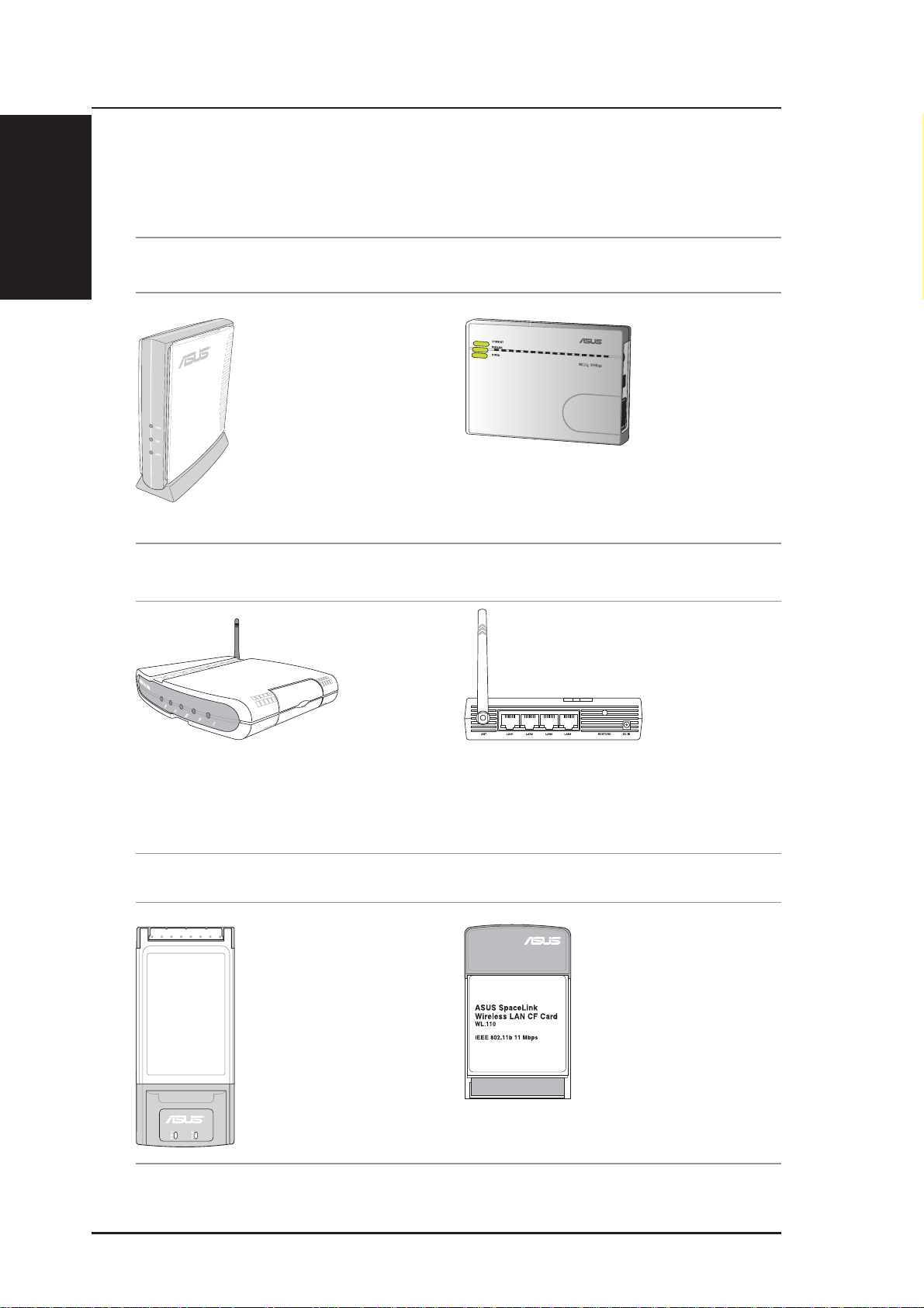
The ASUS Wireless Family
The ASUS W ireless family contains a several wireless network solutions for
802.11g & 802.11b wireless local area networks in the home or office.
Access Point or Client
Access Point & Router
The ASUS WLAN 802.11g
Access Point (WL-300g) creates
a wireless network using the
IEEE 802.11g and 802.11b
wireless standards.
The ASUS 3 in 1
Pocket Access Point
(WL-330g) creates a
wireless network
using the IEEE
802.11g/b wireless
standards.
The ASUS WLAN Gateway (WL-500g) creates a
wireless network using the IEEE 802.11g/b wireless
standards and allows sharing a single Internet
connection.
The ASUS WLAN 802.11g Pocket Router (WL-
530g) creates a wireless network using the IEEE
802.11g and 802.11b wireless standards and allows
sharing a single Internet connection.
PCMCIA Client Compact Flash (CF) Client
The ASUS WLAN PC Card
(WL-107g) is a wireless LAN
adapter that fits into a PCMCIA
T ype II slot in a Notebook PC and
creates a wireless network using
the IEEE 802.11g/b wireless
standards.
(The illustrations are not to scale.)
The ASUS 802.11b Wireless
CF Card (WL-1 10) is a IEEE
802.11b wireless LAN adapter
that fits into a Compact Flash
Type II slot in a Portable
Digital Assistant (PDA).
12 ASUS Wireless Router
Page 13
Chapter 1 - Introduction
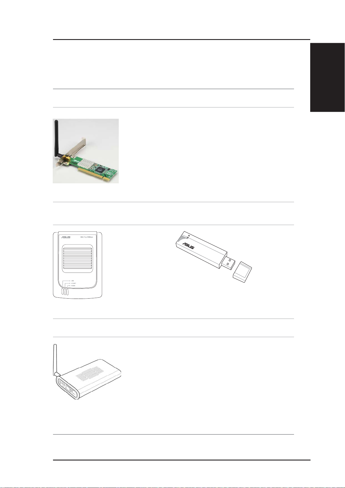
PCI Client
The ASUS WLAN
PCI Card (WL138g) is a wireless
LAN adapter that fits
into a standard PCI
slot in a desktop PC
and creates a wireless
network using the
IEEE 802.11g/b
wireless standards.
USB Access Point or Client USB Client
The ASUS USB Wireless
LAN Adapter (WL-160g)
creates a wireless network
using the IEEE 802.11g/b
wireless standards and
connects to any computer
using USB2.0 connectivity.
802.11g 54Mbps
1. Introduction
The ASUS USB Wireless LAN Adapter (WL-167g)
is thumb-sized and creates a wireless network using
the IEEE 802.11g/b wireless standards and connects
to any computer using USB2.0 connectivity.
Access Point & File Server
The ASUS WLAN 802.11g Access Point (WLHDD) creates a wireless network using the IEEE
802.11g and 802.1 1b wireless standards. Also serves
as a file server (wireless network attached storage).
(The illustrations are not to scale.)
ASUS Wireless Router 13
Page 14

Chapter 1 - Introduction
1. Introduction
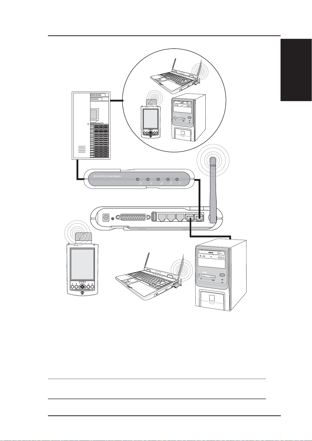
Network Topology
The settings that you need to perform will vary depending on the role that
your ASUS Wireless Router will play.
Network Backbone
No software setting is necessary in the ASUS Wireless Router.
Wireless
ASUS Wireless Router
LAN
Wireless Client
Wireless Client
Wired Client
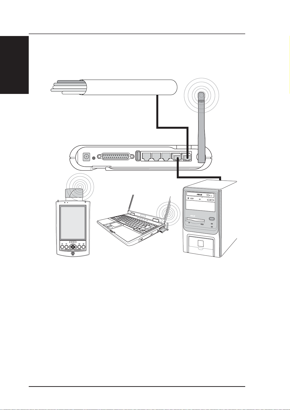
In this topology , the wireless router connects your wired and wireless devices
together to form a local area network (LAN), as shown. To connect a
computer (or other device) to the ASUS Wireless Router , you need a network
cable (UTP-Cat5) with one end connected to one of the LAN ports on the
back of the ASUS W ireless Router and the other in the 10/100 LAN port on
that device. For wireless connections, wireless mobile clients must comply
with the IEEE 802.11b standard.
14 ASUS Wireless Router
Page 15
s
I
Agent to an ISP
Chapter 1 - Introduction
nternet Service Provider
Internet
1. Introduction
ADSL or Cable Modem
ASUS Wireless Router
LAN
Wireles
WAN
Wireless Client
Wireless Client
Wired Client
In this topology, the wireless router is not only a backbone of your LAN
but also an agent to your Internet Service Provider (ISP). You may use an
ADSL or Cable modem to communicate with your ISP. Connect the LAN
port on the modem with the WAN port at the back of the ASUS Wireless
Router using a network cable as shown above.
Note: You also need to make sure that other connections on the
ADSL or Cable modem are correct.
ASUS Wireless Router 15
Page 16
Chapter 1 - Introduction
1. Introduction
Agent to Another Network
Wireless
Network Backbone
WAN
ASUS Wireless Router
LAN
Wireless Client
Wireless Client
Wired Client
In this topology, the wireless router is an agent between your LAN and
another network. Use a network cable with one end connected to the WAN
port on the wireless router and the other to the other network as shown
above.
16 ASUS Wireless Router
Page 17
Chapter 1 - Introduction
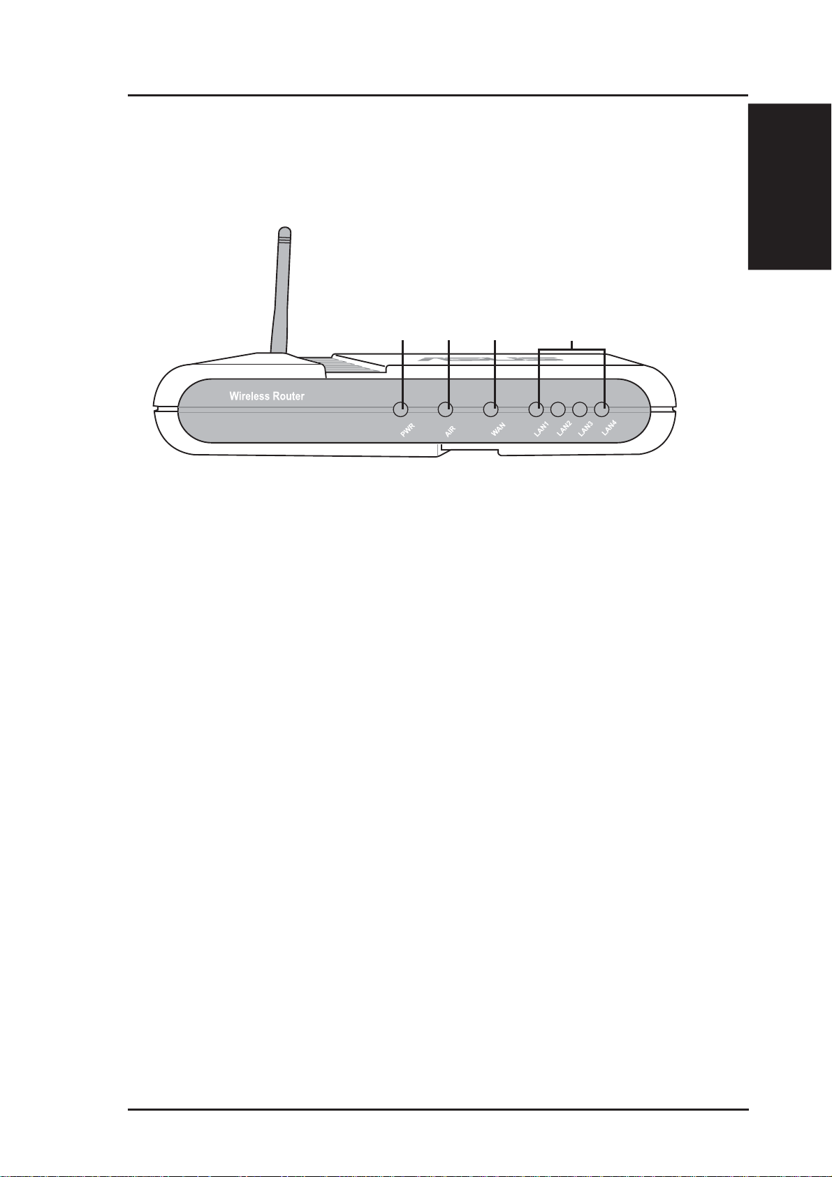
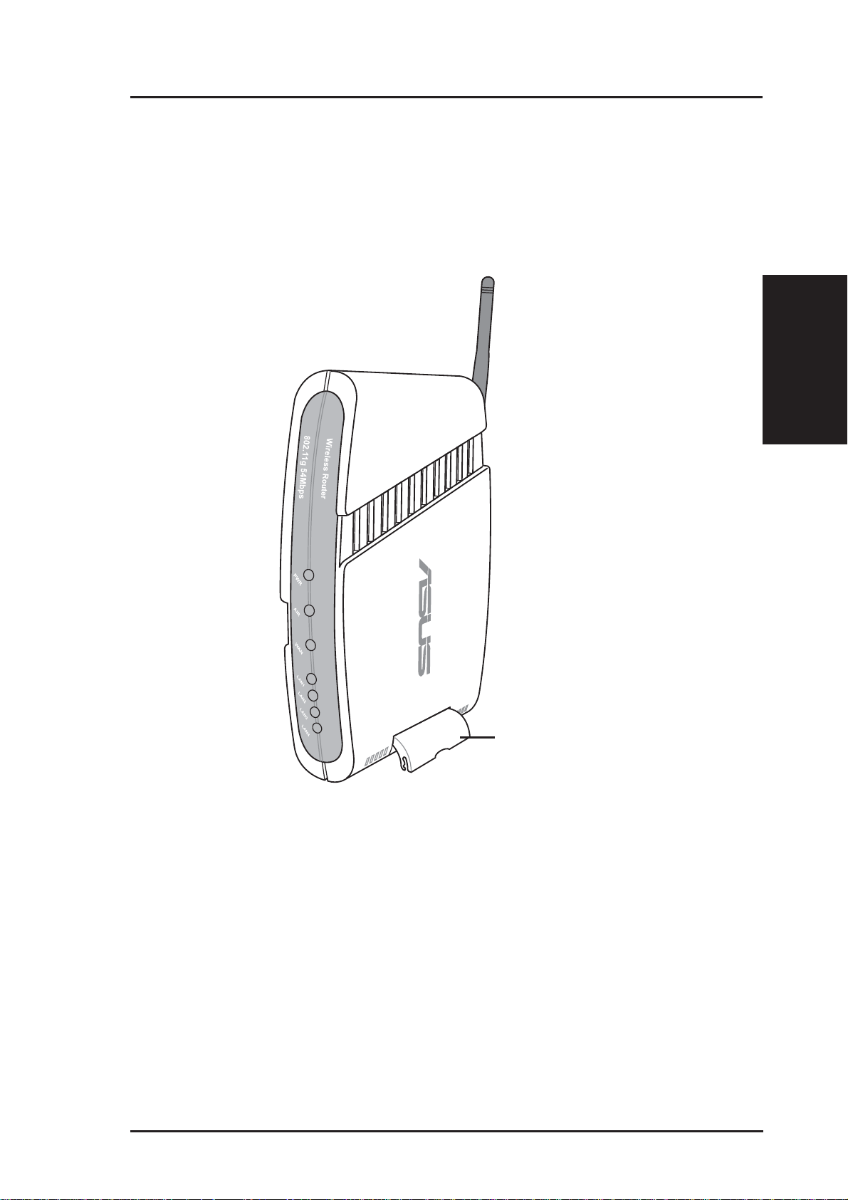
LED Indicators
The LEDs on the front of the ASUS Wireless Router display the status of
the ASUS Wireless Router.
1. Introduction
PWR
WAN LAN
AIR
PWR (Power)
Off No power
On System ready
Flashing Firmware upgrade failed
AIR (Wireless Network)
Off No power
On Wireless system ready
Flashing Transmitting or receiving data (wireless)
WAN (Wide Area Network)
Off No power
On Has physical connection to an Ethernet network
Flashing Transmitting or receiving data (through Ethernet wire)
LAN 1-4 (Local Area Network)
Off No power
On Has physical connection to an Ethernet network
Flashing Transmitting or receiving data (through Ethernet wire)
ASUS Wireless Router 17
Page 18

Chapter 2 - Installation
2. Installation Procedure
Follow these steps to install the ASUS Wireless Router.
1. Determine the best location for the ASUS Wireless Router. Keep in mind
the following considerations:
• The length of the Ethernet cable that connects the ASUS Wireless
2. Installation
• Try to place the ASUS Wireless Router on a flat, sturdy surface as
• Try to centrally locate the ASUS Wireless Router so that it will pro-
• Use only the power supply that came with this unit. Other power
Router to the network must not exceed 100 meters.
far from the ground as possible, such as on top of a desk or bookcase, keeping clear of obstructions and away from direct sunlight.
vide coverage to all of the wireless mobile devices in the area. Orientating the antenna vertically should provide the best reception.
supplies may fit but the voltage and power may not be compatible.
2. Wall mounting or vertical standing is also possible.
It is the responsibility of the installer and users of the ASUS Wireless Router to guarantee that the antenna is operated at least 20
centimeters from any person. This is necessary to insure that the
product is operated in accordance with the RF Guidelines for Human Exposure which have been adopted by the Federal Communications Commission.
4. LAN Connection: Attach one end of an RJ-45 Ethernet cable to the ASUS
Wireless Router’ s LAN port (any one of the four) and attach the other end
to the RJ-45 Ethernet cable to your desktop computer .
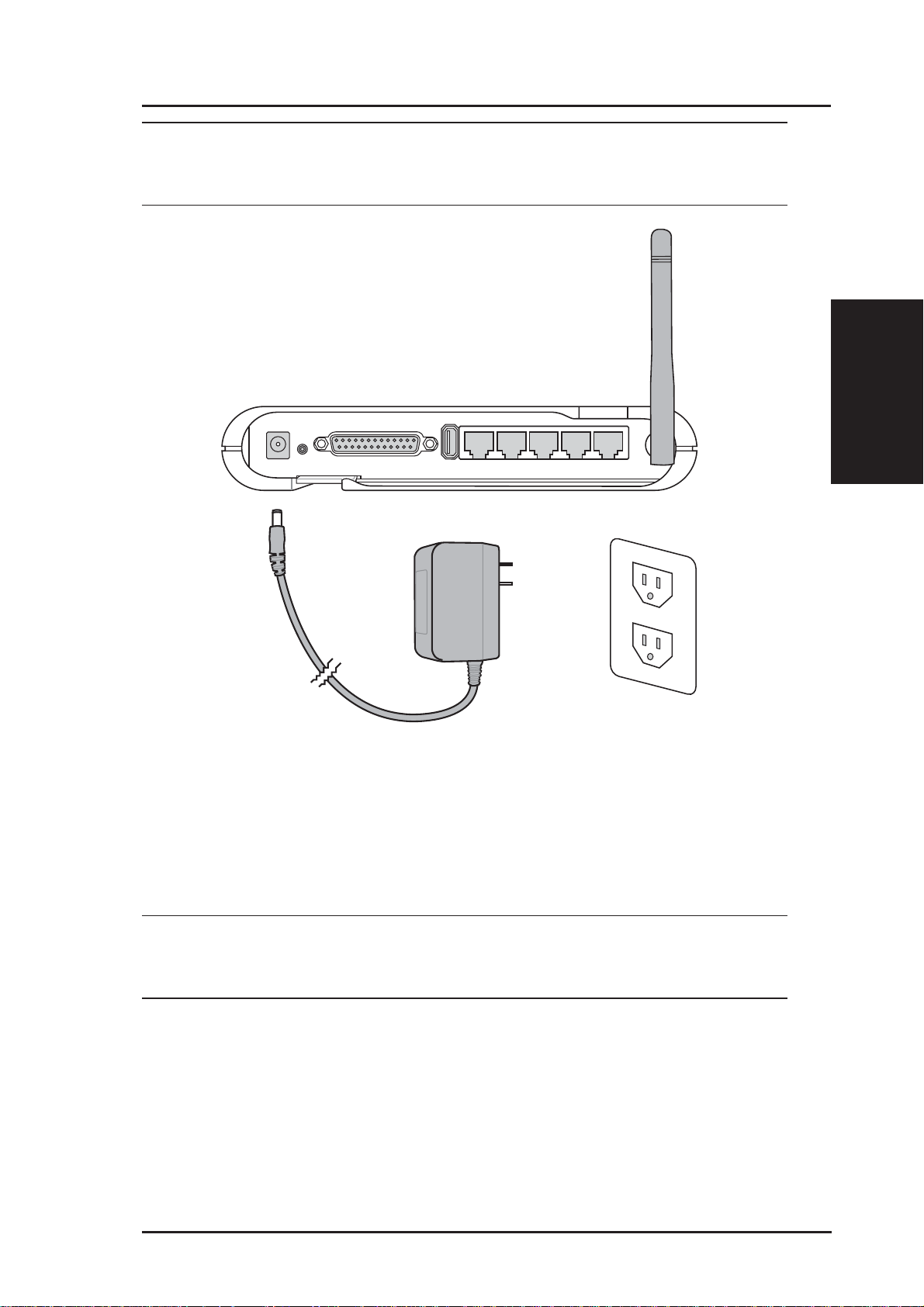
5. Power Connection: The ASUS Wireless Router requires power from an
external power supply . The ASUS Wireless Router ships with a UL listed,
Class 2 power supply (5V). Attach one end of the DC power adapter to the
back of the ASUS Wireless Router and the other end to a power outlet.
The Power LED on the front of the ASUS Wireless Router will light up
when the unit is powered ON. In addition, the green LAN or WAN LEDs
will turn ON to indicate that the ASUS Wireless Router has a physical
Ethernet network connection.
18 ASUS Wireless Router
Page 19
Chapter 2 - Installation
Warning: Use the ASUS Wireless Router only with the power adapter
supplied in the product package. Using another power supply may
damage the ASUS Wireless Router.
2. Installation
6. Printer Connection: Connect a printer to the Wireless Router printer
port (WL500g/WL500b only) or USB port to use the router as a printing
server for your local network.
7. USB Connection: Connect a supported USB web camera or USB
storage device to the Wireless Router USB port.
Note: Before using an embedded USB application or device, refer
to the USB storage and USB camera support list on the ASUSTeK
Web site at the following Internet address: http://www.asus.com.
ASUS Wireless Router 19
Page 20
Chapter 2 - Installation
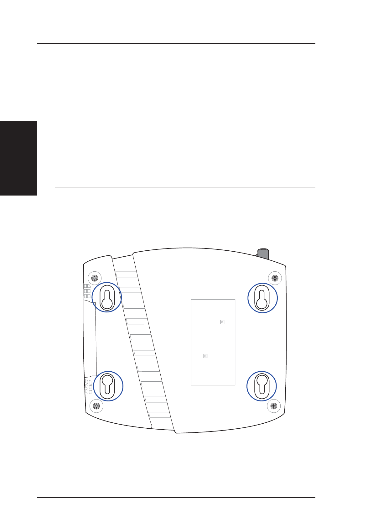
W all Mounting Option
Out of the box, the ASUS W ireless Router is designed to sit on a raised flat
surface like a file cabinet or book shelf. The unit may also be converted for
mounting to a wall or ceiling.
Follow these steps to mount the ASUS Wireless Router to a wall:
2. Installation
1. Look on the underside for the four mounting hooks.
2. Mark two upper holes in a flat surface using the provided hole template.
3. Tighten two screws until only 1/4” is showing.
4. Latch the upper two hooks of the ASUS Wireless Router onto the screws.
Note: Readjust the screws if you cannot latch the ASUS Wireless
Router onto the screws or if it is too loose.
20 ASUS Wireless Router
Page 21
Chapter 2 - Installation
Vertical Standing Option
The ASUS Wireless Router can also stand on its side to save space. Two
hinges can be opened on the right side to support vertical standing. Orientate
the antenna so that it points upwards.
2. Installation
Support Hinge
ASUS Wireless Router 21
Page 22
Chapter 2 - Installation
Connecting to the ASUS W ireless Router
Wired Connection
One RJ-45 cable is supplied with the ASUS Wireless Router . Auto crossover
function is designed into the ASUS W ireless Router so you can use either a
straight-through or a crossover Ethernet cable. Plug one end of the cable
2. Installation
into the WAN port on the rear of the ASUS Wireless Router and the other
end into the Ethernet port of your ADSL or Cable modem.
Wireless-Connection
Refer to your wireless adapter user’s manual on associating with the ASUS
Wireless Router . The default SSID of the ASUS Wireless Router is “default”
(lower case), encryption is disabled and open system authentication is used.
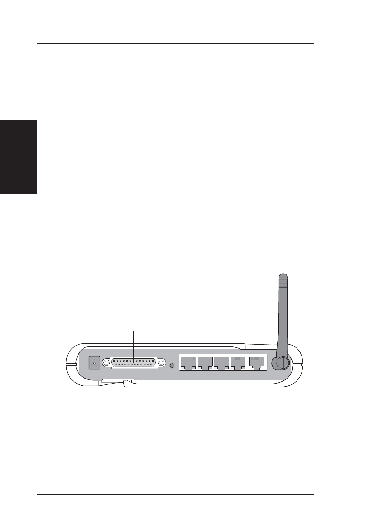
Printer Connection (WL500g/WL500b only)
A DB25 parallel cable should be supplied with your printer. Plug the male
connector of this parallel cable into the printer port on the rear of the ASUS
Wireless Router and the centronics end into your printer.
Printer Port
22 ASUS Wireless Router
Page 23
Chapter 3 - Software Configuration
3. Software Configuration
Configuring the ASUS Wireless Router
The ASUS Wireless Router can be configured to meet various usage
scenarios. Some of the factory default settings may suit your usage; however,
others may need changing. Prior to using the ASUS Wireless Router, you
must check the basic settings to guarantee it will work in your environment.
Configuring the ASUS Wireless Router is done through a web browser.
You need a Notebook PC or desktop PC connected to the ASUS Wireless
Router (either directly or through a hub) and running a web browser as a
configuration terminal. The connection can be wired or wireless. For the
wireless connection, you need an IEEE 802.11g/b compatible device, e.g.
ASUS WLAN Card, installed in your Notebook PC. Y ou should also disable
WEP and set the SSID to “default” for your wireless LAN device. If you
want to configure the ASUS Wireless Router or want to access the Internet
through the ASUS Wireless Router, TCP/IP settings must be correct.
Normally, the TCP/IP setting should be on the IP subnet of the ASUS
Wireless Router.
3. Utilities
Note: Before rebooting your computer, the ASUS Wireless Router
should be switched ON and in ready state.
Setting IP address for Wired or Wireless Connection
Get IP Automatically
The ASUS Wireless Router
incorporates a DHCP server so the
easiest method is to set your PC to
get its IP address automatically and
reboot your computer. So the
correct IP address, gateway, DNS
(Domain Name System Server)
can be obtained from the ASUS
Wireless Router.
Note: Before rebooting your
PC, the ASUS Wireless Router
should be switched ON and in
ready state.
ASUS Wireless Router 23
Page 24
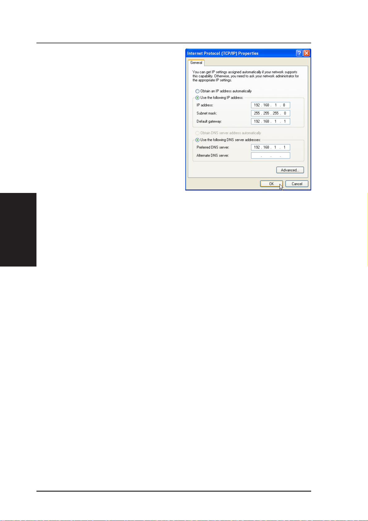
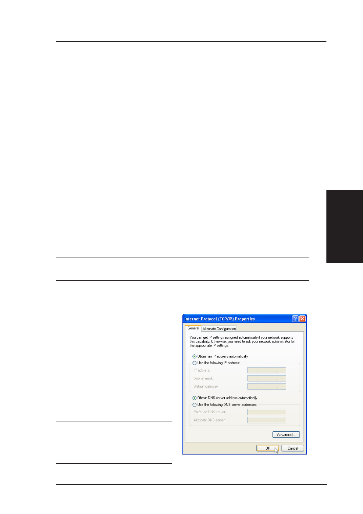
Setting IP Manually
If you want to set your IP address
manually, the following default
settings of the ASUS Wireless
Router should be known:
• IP address 192.168.1.1
• Subnet Mask 255.255.255.0.
If you set your computer’s IP
manually , it needs to be on the same
segment. For example:
• IP address 192.168.1.xxx (xxx
3. Utilities
• Subnet Mask 255.255.255.0 (same as the ASUS Wireless Router)
Chapter 3 - Software Configuration
can be any number between 2
and 254 that is not used by
another device)
• Gateway 192.168.1.1 (this is the ASUS Wireless Router)
• DNS 192.168.1.1 (ASUS Wireless Router IP address or your own).
24 ASUS Wireless Router
Page 25
Chapter 3 - Software Configuration
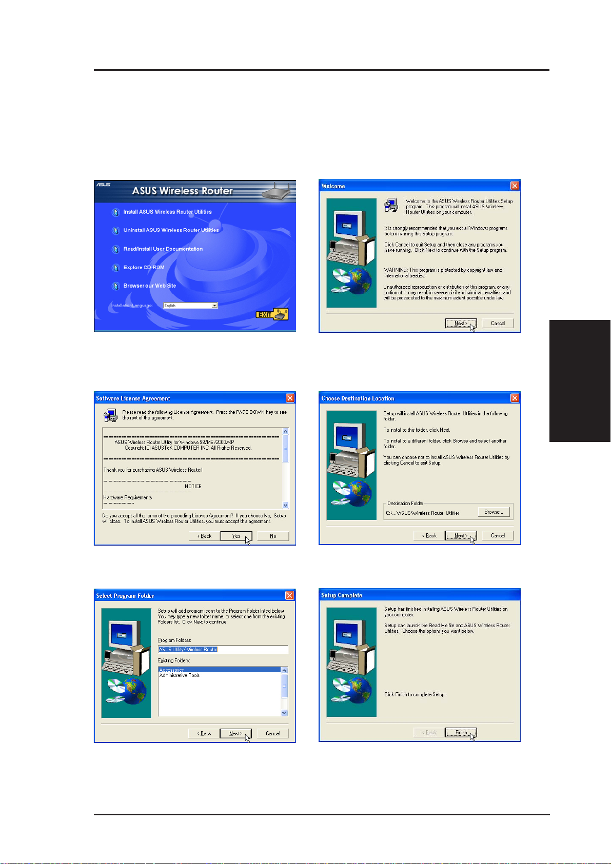
Installing the ASUS Wireless Router Utilities
Follow these steps to install the ASUS Wireless Router Utilities in Microsoft
Windows. Insert the support CD provided with the ASUS W ireless Router and
the menu will appear . (Double-click setup.exe if your autorun has been disabled.)
(1) Select a language and click Install
ASUS Wireless Router Utilities.
(3) Click Yes after reading the license
agreement.
(2) Click Next after reading the welcome
screen.
3. Utilities
(4) Click Next to accept the default
destination folder or enter another.
(5) Click Next to accept the default
program folder or enter another.
ASUS Wireless Router 25
(6) Click Finish when setup is complete.
Page 26
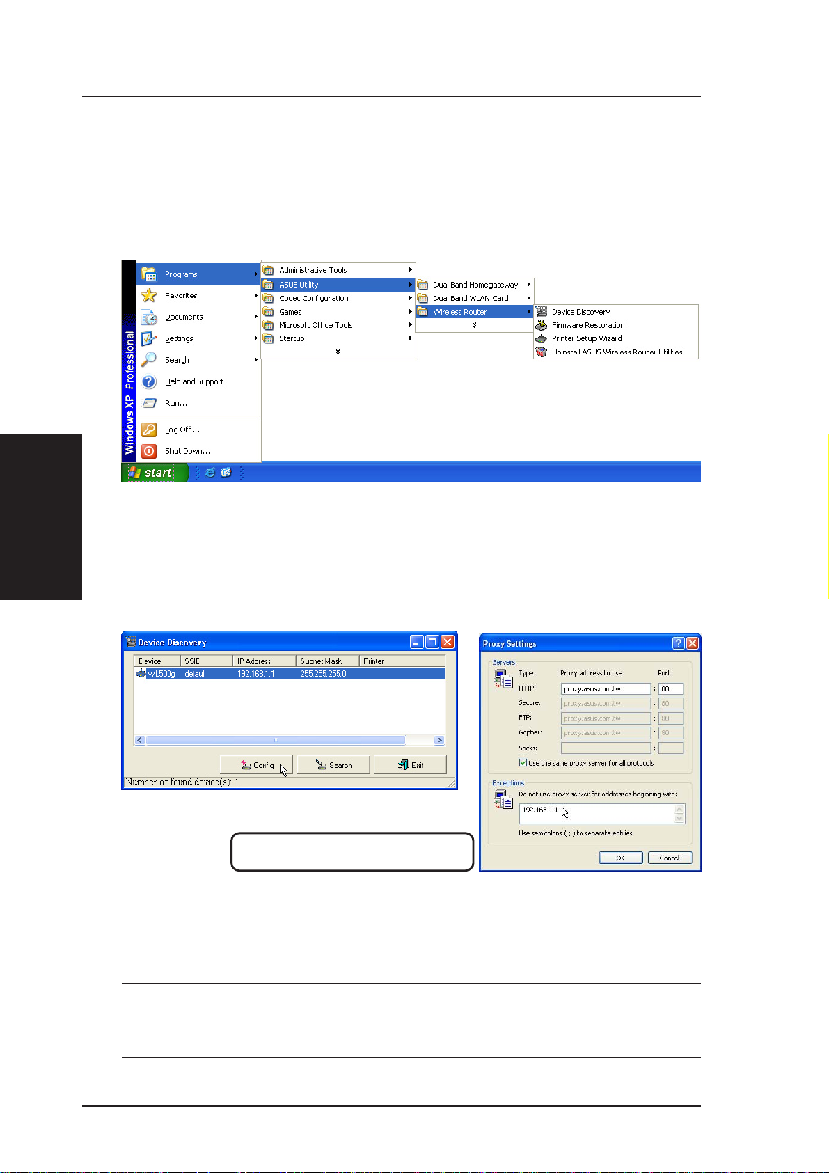
Using the Wireless Router for the First Time
1. ASUS Wireless Router Utilities
Run Device Discovery from “ASUS Utility” in W indows Start Programs.
3. Utilities
Chapter 3 - Software Configuration
2. Connect to the ASUS WLAN Web Manager
Run the ASUS WLAN Device Discovery from the Start menu and click
Config when the device is found.
Microsoft® Internet Explorer
Add 192.168.1.1 in the Exceptions box if you are
using a proxy server (Microsoft
If your computer’s IP is not on the same subnet as the ASUS Wireless Router
(192.168.1.X), you will be asked to change it. The IP address can be any number
from 2 to 254 that is not used by another device. Gateway is not required.
®
Internet Explorer).
Note: Using a proxy server (Microsoft® Internet Explorer) for your
LAN requires that you set an exception for the ASUS Wireless Router
or else connection will fail.
26 ASUS Wireless Router
Page 27
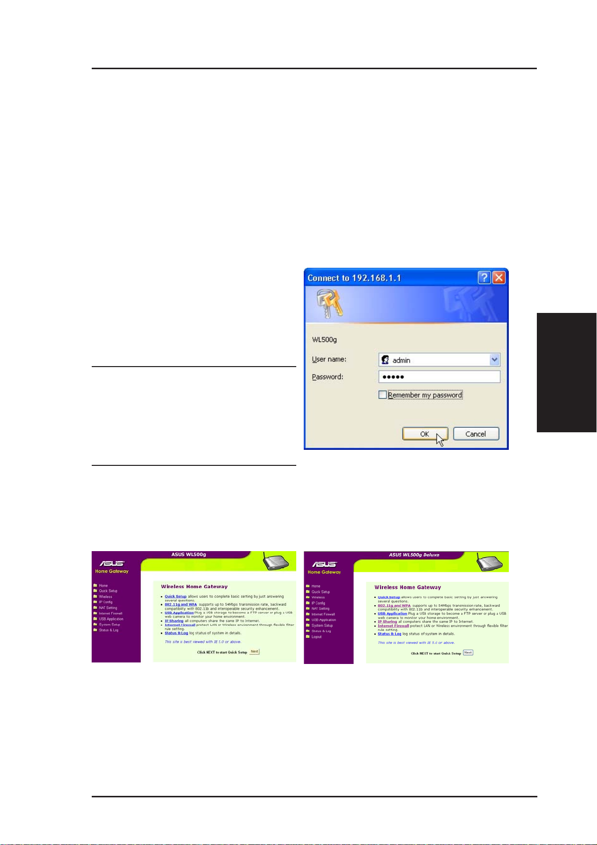
Chapter 3 - Software Configuration
Enter Address or Name Manually
Y ou can also open your PC’ s web browser and enter the name or the default
IP address of the ASUS Wireless Router:
WL500g
http://my.router or http://my.WL500g or http://192.168.1.1
WL500g Deluxe
http://my.router or http://my.WL500gx or http://192.168.1.1
User Name & Password
Once connected, a window will ask
for the User name and Password in
order to log in. The factory default
values are “admin” and “admin”.
Note: If you cannot find any the
ASUS Wireless Routers due to
a problem in the IP settings,
push and hold the “Restore”
button over five seconds to restore factory default settings.
Home Page
After logging in, you will see the ASUS Wireless Router home page.
3. Utilities
WL500g
WL500g Deluxe
ASUS Wireless Router 27
Page 28
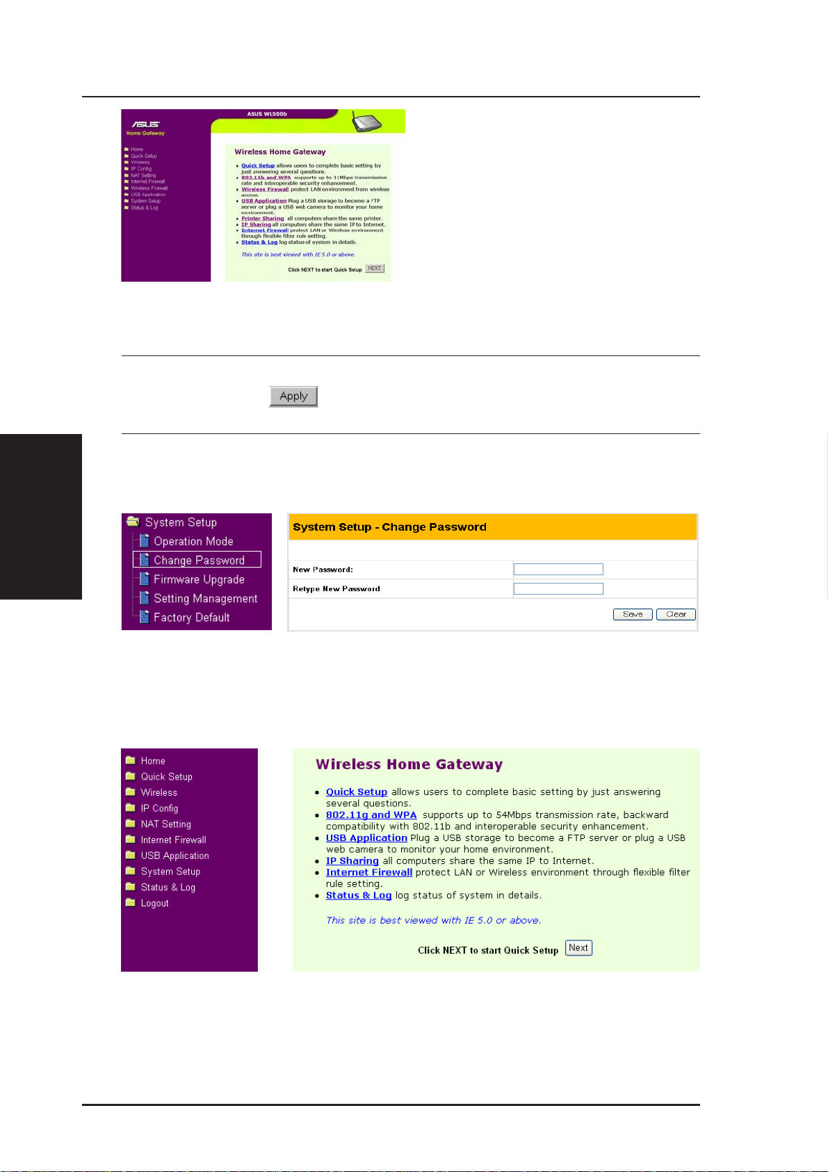
Chapter 3 - Software Configuration
WL500b
IMPORTANT: After entering information on any page, click the
“Apply” button
rected to another page and lose your new settings.
. If you click any other link, you will be di-
3. Utilities
3. Set your own password
4. Use Quick Setup
28 ASUS Wireless Router
Page 29
Chapter 3 - Software Configuration
Home Gateway Mode
There are three operation modes in the ASUS
Wireless Router. The default operation mode of the
ASUS Wireless Router is Home Gateway Mode.
Please refer to “System Setup” – “Operation Mode”
in detail. To start quick setup, click Next to enter
the “Quick Setup” page. Follow the instructions to
setup the ASUS Wireless Router.
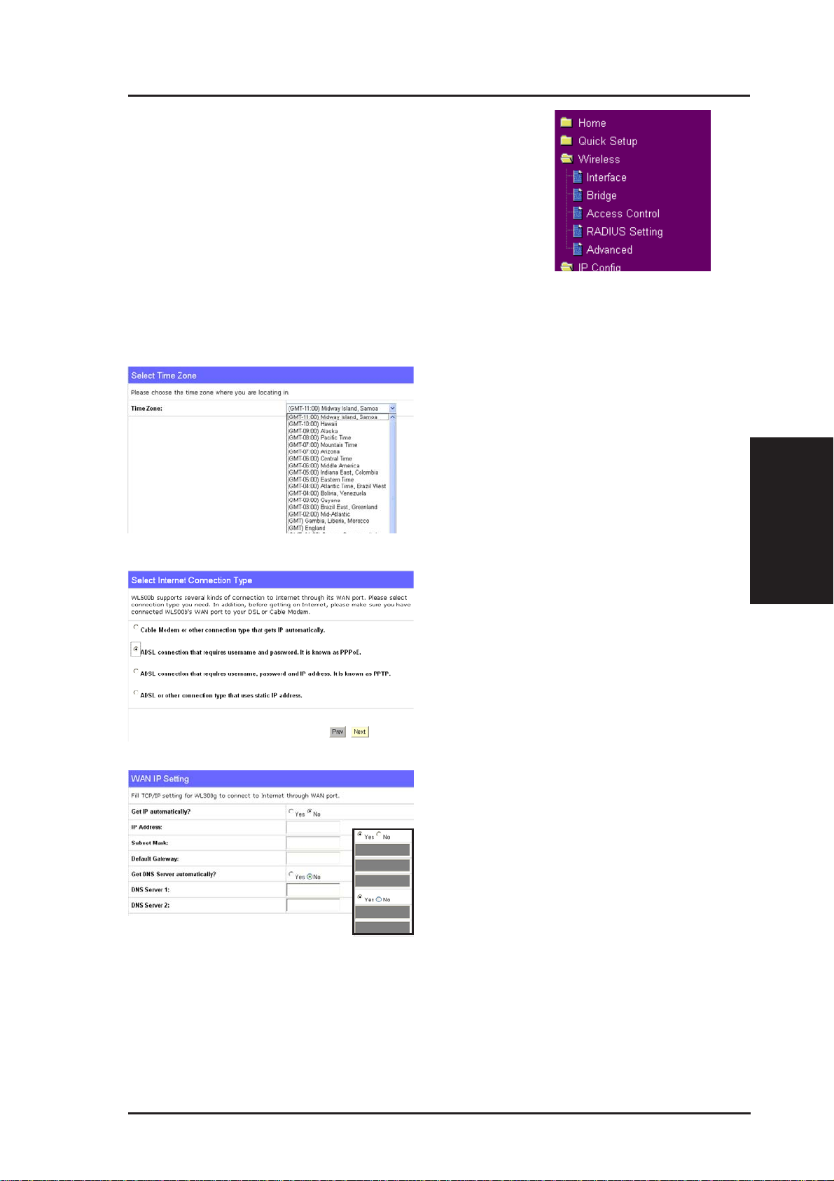
Quick Setup in Home Gateway Mode
Select your time zone or the closest
region. Click Next to continue.
Select the connection type. Click
Next to continue.
Select “No” to enter the information
manually . “Y es” will disable the field.
Click Next to continue.
3. Utilities
ASUS Wireless Router 29
Page 30
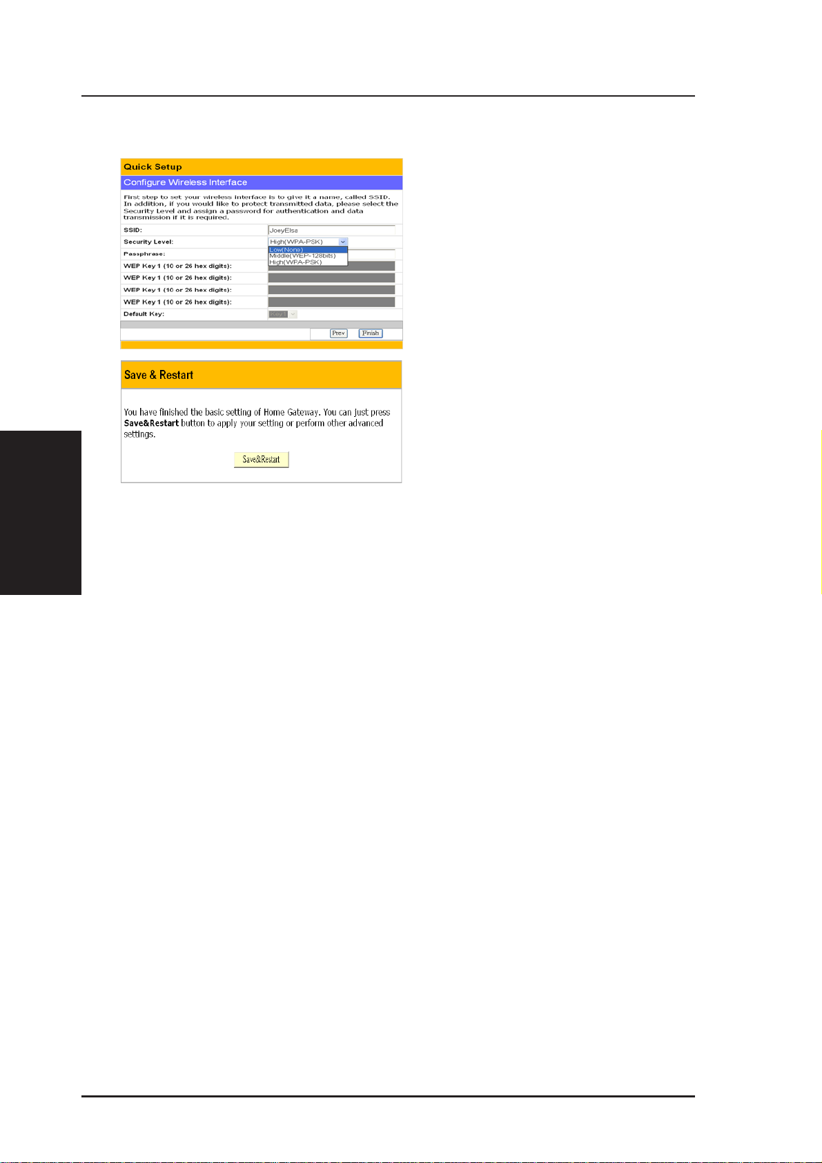
Home Gateway Mode (Cont.)
3. Utilities
transmitted data, select a middle or high Security Level.
Chapter 3 - Software Configuration
To set up your wireless interface,
you must first give it an SSID
(Service Set Identifier). The SSID
is a unique identifier attached to
packets sent over WLANs. This
identifier emulates a password
when a wireless device attempts
communication on the WLAN.
Because an SSID distinguishes
WLANs from each other, access
points and wireless devices trying
to connect to a WLAN must use the
same SSID.
Also, if you want to protect
Middle: allows only those users with the same WEP key to connect to this
access point and to transmit data using 128-bit WEP encryption.
High: allows only those users with the same WP A pre-shared key to connect
to this access point and to transmit data using TKIP encryption.
Click Finish to continue. You are prompted to save the settings. Click
Save&Restart to save the settings to the ASUS W ireless Router and enable
the new settings.
30 ASUS Wireless Router
Page 31

Chapter 3 - Software Configuration
T o adjust other settings, click an item
on the menu to reveal a submenu and
follow the instructions to setup the
ASUS Wireless Router. Tips are
given when you move your cursor
over each item. The following have
submenu items:
• Wireless
• IP Config
• NAT Setting
• Internet Firewall
• USB Application
• System Setup
• Status & Log
3. Utilities
ASUS Wireless Router 31
Page 32

Wireless
Click an item on the menu to reveal a submenu.
Follow the instructions to set up the ASUS W ireless
Router. Tips are displayed when you move your
cursor over an item.
Interface
WL500b WL500g/WL500g Deluxe
3. Utilities
Chapter 3 - Software Configuration
SSID
The SSID is an identification string of up to 32 ASCII characters that
differentiate one ASUS Wireless Router AP or Access Point from other
manufacturers. The SSID is also referred to as the “ESSID” or “Extended
Service Set ID.” You can use the default SSID and radio channel unless
more than one ASUS Wireless Router or Access Point is deployed in the
same area. In that case, you should use a different SSID and radio channel
for each ASUS Wireless Router or Access Point. All ASUS W ireless Routers
and ASUS 802.11g/802.11b WLAN client adapters must have the same
SSID to allow a wireless mobile client to roam between the ASUS W ireless
Routers . By default, the SSID is set to “default”.
32 ASUS Wireless Router
Page 33

Chapter 3 - Software Configuration
Wireless (Cont.)
Channel
The 802.11g and 802.11b specifications supports up to 14 overlapping
channels for radio communication. To minimize interference, configure
each ASUS 802.11g AP to be non-overlapping; select Auto from the Channel
drop-down list to enable the system to select a clear channel during boot up
as your operating channel.
Ensure that ASUS W ireless Routers sharing the same channel (or channels
which are close in number) are as far away from each other as possible,
based on the results of your site survey of the facility . There is a site survey
utility on the ASUS Wireless Router setup CD.
Wireless Mode (WL500g/WL500g Deluxe Only)
This field indicates the 802.11g interface mode. Selecting “Auto” allows
802.11g and 802.11b clients to connect to the ASUS Wireless Router.
Selecting “54g Only” maximizes performance, but prevents 802.11b clients
from connecting to the ASUS Wireless Router. If “54g Protection” is
checked, G-Mode protection of 11g traffic is enabled automatically in the
presence of 11b traffic.
3. Utilities
ASUS Wireless Router 33
Page 34

Chapter 3 - Software Configuration
Wireless (Cont.)
Authentication
Method Encryption Passphrase WEP Key 1~4
Open or shared key None Not required Not required
WEP-64 bits 1~64 characters 10 hex
WEP-128 bits 1~64 characters 26 hex
Shared key WEP-64 bits 1~64 characters 10 hex
WEP-128 bits 1~64 characters 26 hex
3. Utilities
* WL500g/WL500g Deluxe supports AES and TKIP encryption for WPA.
^ WL500b does not support WPA and Radius with 802.1x and WL500b only supports TKIP encryption for WPA-PSK.
WEP Encryption
Traditional WEP encryption is applied when “Open or Shared Key”, “Shared
Key” or “Radius with 802.1x” authentication methods are selected.
WPA-PSK
WPA
Radius with 802.1x
^
^
^ Auto Not required Not required
TKIP only * 8~63 characters Not required
AES only * 8~63 characters Not required
TKIP only * Not required Not required
AES only * Not required Not required
WEP-64 bits 1~64 characters 10 hex
WEP-128 bits 1~64 characters 26 hex
WL500g/WL500g Deluxe: When “WPA” or “WPA-PSK” authentica-
tion methods are selected, you still can set WEP encryption for
those clients that do not support WPA/WPA-PSK. Please note that
Key Index for WEP key is limited to 2 or 3 when both WPA and WEP
encryption are supported at the same time.
64/128-bit versus 40/104-bit
The following section explains low-level (64-bit) and high-level (128-bit)
WEP Encryption schemes:
34 ASUS Wireless Router
Page 35

Chapter 3 - Software Configuration
Wireless (Cont.)
64-bit WEP Encryption
64-bit WEP and 40-bit WEP are the same encryption method and can
interoperate in a wireless network. This level of WEP encryption uses a
40-bit (10 Hex character) encryption scheme as a secret key, which is set
by the user, and a 24-bit “Initialization Vector” scheme, which is not under
user control.
Together these two schemes make a 64-bit (40 + 24) encryption scheme.
Some vendors refer to this level of WEP as 40-bit and others refer to this as
64-bit. ASUS WLAN products use the term 64-bit when referring to this
lower level of encryption.
128-bit WEP Encryption
104-bit WEP and 128-bit WEP are the same encryption method and can
interoperate on a wireless network. This level of WEP encryption uses a
104-bit (26 Hex character) encryption scheme as a secret key which is set
by the user, and a 24-bit “Initialization Vector”, which is not under user
control.
T ogether these two schemes make a 128-bit (104 + 24) encryption scheme.
Some vendors refer to this level of WEP as 104-bit and others refer to this
as 128-bit. ASUS WLAN products use the term 128-bit when referring to
this higher level of encryption.
Passphrase
Selecting “WEP-64bits” or “WEP-128bits” in the Encryption field generates
four WEP keys automatically. A combination of up to 64 letters, numbers,
or symbols is required. Alternatively , leave this field blank and type in four
WEP keys manually.
¥ WEP-64bit key: 10 hexadecimal digits (0~9, a~f, and A~F)
3. Utilities
¥ WEP-128bit key: 26 hexadecimal digits (0~9, a~f, and A~F)
Note: The ASUS WLAN family of products uses the same algorithm
to generate WEP keys, eliminating the need for users to remember
passwords and to maintain compatibility between products. However, using this method to generate WEP keys is not as secure as
manual assignment.
ASUS Wireless Router 35
Page 36

Wireless (Cont.)
WEP Key
You can set a maximum of four WEP keys. A WEP key is either 10 or 26
hexadecimal digits (0~9, a~f, and A~F) based on whether you select 64bits
or 128bits in the WEP pull-down menu. The ASUS Wireless Router and
ALL of its wireless clients MUST have at least the same default key.
Key Index
The Default Key field lets you specify which of the four encryption keys
you use to transmit data on your wireless LAN. As long as the ASUS
Wireless Router or wireless mobile client with which you are communicating
has the same key in the same position, you can use any of the keys as the
default key. If the ASUS Wireless Router and ALL of its wireless clients
3. Utilities
use the same four WEP keys, select “key rotation” to maximize security.
Otherwise, choose one key in common as the default key.
Chapter 3 - Software Configuration
Network Rotation Key Interval
This field specifies the time interval (in seconds) after which a WPA group
key is changed. Enter ‘0’ (zero) to indicate that a periodic key-change is
not required.
36 ASUS Wireless Router
Page 37

Chapter 3 - Software Configuration
Wireless
Click an item on the menu to reveal a submenu.
Follow the instructions to set up the ASUS W ireless
Router. Tips are displayed when you move your
cursor over an item.
Bridge/Access Control List
AP Only
Hybrid
WDS Only (WL500g/WL500g Deluxe)
3. Utilities
Wireless bridge (also known as
Wireless Distribution System or
WDS) allows you to connect to one
or many Access Points.
ASUS Wireless Router 37
Page 38

Wireless (Cont.)
AP Mode
AP (Access Point) Mode configures the ASUS W ireless Router for a specific
application. By default, the ASUS Wireless Router is configured as an
Access Point which enables wireless mobile clients to connect wirelessly
to a wired Ethernet network. The following options are available from the
drop-down list:
3. Utilities
Chapter 3 - Software Configuration
AP Only: the ASUS Wireless Router acts only as an Access Point.
WDS Only (WL500g/WL500g Deluxe): the ASUS Wireless Router
can only communicate with other Access Points.
Hybrid: Hybrid allows you to use the ASUS Wireless Router both as
an access point and as a wireless bridge.
Channel
Both Access Points in Wireless Bridge mode must be set to the same channel.
Connect to APs in Remote Bridge List (Yes/No)
Select Yes to connect to access points in the remote bridge list.
Allow anonymous? (Yes/No) (WL500g/WL500g Deluxe)
Select Yes to allow users without accounts to connect.
Note: If “Connect to APs in Remote Bridge List” and “Allow Anonymous” are both set to “No”, it means that this AP will not connect with
other APs and therefore the AP mode setting will return to “AP Only”.
38 ASUS Wireless Router
Page 39

Chapter 3 - Software Configuration
Wireless (Cont.)
MAC Address
Enter the MAC address of the target ASUS Wireless Router in order to
designate which ASUS Wireless Router will be the partner for this ASUS
Wireless Router.
You can setup your wireless environment as shown in this figure:
Note: The content in braces “( )” is the MAC address in the Remote
Bridge List of the AP. For example, WB1 have the MAC address of
WB in its Remote Bridge List.
In this case, there are six ASUS Wireless Routers and they are linked as
wireless bridges. Take one of them, named WB, as an example. WB is not
in “AP Only” mode and “Connect to APs in Remote Bridge List” is set as
“Yes”, so it can connect to WB3. Meanwhile, “allow anonymous” is set as
“Yes” or “Allow anonymous” is set as “No” but it has the MAC addresses
of WB1, WB2, and WB4 in the “Remote Bridge List”, so it can be connected
by WB1, WB2, and WB4.
3. Utilities
ASUS Wireless Router 39
Page 40

Wireless
Click an item on the menu to reveal a submenu.
Follow the instructions to set up the ASUS W ireless
Router. Tips are displayed when you move your
cursor over an item.
Access Control
3. Utilities
Chapter 3 - Software Configuration
Pull down menu items:
Disable (no info required)
Accept (need to input information)
Reject (need to input information)
T o add security , the ASUS W ireless Router has the ability to only associate
with or not associate with wireless mobile clients that have their MAC
address entered into this page.
The default setting of “Disable” will allow any wireless mobile client to
connect. “Accept” will only allow those entered into this page to connect.
“Reject” will prevent those entered into this page from connecting.
Adding a MAC Address
To add a MAC address, enter the 12 hexadecimal characters into the white box
next to “MAC Address:” and click the Add button. The MAC address will be
placed in the control list below . Only a total of 31 MAC addresses can be entered
into this page so determine which will be the lesser; those you wish to accept or
those you wish to reject and click the appropriate “MAC Access Mode”.
Note: Click the “Finish” button to save your new settings and restart the ASUS Wireless Router or click “Save” and restart later.
40 ASUS Wireless Router
Page 41

Chapter 3 - Software Configuration
Wireless
Click an item on the menu to reveal a submenu.
Follow the instructions to set up the ASUS W ireless
Router. Tips are displayed when you move your
cursor over an item.
Radius Setting (WL500g/WL500g Deluxe)
This section enables you to set up
additional parameters for connection
with a RADIUS Server. Values are
required for this page when the
Authentication Method field in the
Wireless - Interface screen are set as
“WPA” or “Radius with 802.1x”.
Refer to Authentication Method on
page 32.
Server IP Address – specifies the IP address of the RADIUS server to use
for 802.1X wireless authentication and dynamic WEP key derivation.
Server Port – specifies the UDP port number used by the RADIUS server .
Login Secret – specifies the password used to initialize a RADIUS
connection.
Note: A RADIUS server is used for remote user authentication and
accounting. It is primarily used by Internet Service Providers, but
can also be used on any network that needs a centralized authentication function for its workstations.
3. Utilities
ASUS Wireless Router 41
Page 42

Wireless
Click an item on the menu to reveal a submenu.
Follow the instructions to set up the ASUS W ireless
Router. Tips are displayed when you move your
cursor over an item.
Advanced
3. Utilities
Chapter 3 - Software Configuration
This section allows you to set up
additional parameters for the wireless
router function. We recommend that
you use the default values for all
items in this window.
AfterBurner (WL500g Deluxe only)
Enable AfterBurner: (WL500g Deluxe) - Set to Enable to increase
performance for clients (such as WL100gx) that support this function.
Note: Y our network speed will slow down if you have mixed 802.1 1g
and Afterburner clients.
Hide SSID - By default, “No” is selected so that wireless mobile users can
see your ASUS W ireless Router’ s SSID and join. If “Yes” is selected, your
ASUS Wireless Router will not show in site surveys by wireless mobile
clients and they will have to manually enter your ASUS Wireless Router’s
SSID. If you want to restrict access to “your” ASUS W ireless Router , this
is a simple way to do it but for security reasons, don’t forget to change the
SSID to something other than “default”.
Set AP Isolated (WL500g/WL500g Deluxe) - Selecting Yes to prevent
wireless client from communicating with each other.
Data Rate (Mbps) (WL500g/WL500g Deluxe) - This field allows you to
specify the transmission rate. Leave on “Auto” to maximize performance
versus distance.
42 ASUS Wireless Router
Page 43

Chapter 3 - Software Configuration
Wireless (Cont.)
Basic Rate Set (WL500g/WL500g Deluxe) - This field indicates the basic
rates that wireless clients must support. Use “1 & 2 Mbps” only when
backward compatibility is needed for some older wireless LAN cards with
a maximum bit rate of 2Mbps.
Fragmentation Threshold (256-2346) – Fragmentation is used to divide
802.11 frames into smaller pieces (fragments) that are sent separately to
the destination. Enable fragmentation by setting a specific packet size
threshold. If there is an excessive number of collisions on the WLAN,
experiment with different fragmentation values to increase the reliability
of frame transmissions. The default value (2346) is recommended for normal
use.
RTS Thr eshold (0-2347) – The R TS/CTS (Request to Send/Clear to Send)
function is used to minimize collisions among wireless stations. When
RTS/CTS is enabled, the router refrains from sending a data frame until
another RTS/CTS handshake is completed. Enable RTS/CTS by setting a
specific packet size threshold. The default value (2347) is recommended.
DTIM Interval (1-255) (WL500g/WL500g Deluxe) – DTIM (Delivery
Traf fic Indication Message) is a wireless message used to inform clients in
Power Saving Mode when the system should wake up to receive broadcast
and multicast messages. Type the time interval in which the system will
broadcast a DTIM for clients in Power Saving Mode. The default value (3)
is recommended.
3. Utilities
Beacon Interval (1-65535) – This field indicates the time interval in
milliseconds that a system broadcast packet, or beacon, is sent to synchronize
the wireless network. The default value (100 milliseconds) is recommended.
Enable Frame Bursting? (WL500g/WL500g Deluxe) – This field allows
you to enable frame-bursting mode to improve performance with wireless
clients that also support frame-bursting.
Enable Radio? (WL500g/WL500g Deluxe) - Selecting “Yes” enables the
wireless function during user-defined dates and times. Wireless users will
not be able to connect on non-selected dates and times.
Date to Enable Radio (WL500g/WL500g Deluxe) - This field defines
the dates that the wireless function will be enabled.
Time to Enable Radio (WL500g/WL500g Deluxe) - This field defines
the time range that the wireless function will be enabled on each of the
selected dates.
ASUS Wireless Router 43
Page 44

IP Config
WAN & LAN
Click an item on the menu to reveal a submenu.
Follow the instructions to set up the ASUS W ireless
Router. Tips are displayed when you move your
cursor over an item.
WL500g
3. Utilities
Chapter 3 - Software Configuration
WL500g Deluxe
WAN Connection Type
The ASUS Wireless Router supports four connection types to WAN,
including Static IP, PPPoE, PPTP and Automatic IP. WL500g Deluxe
includes “Big Pond” (Telstra) in “WAN Connection Type” and “WAN
Connection Speed”. The WAN setting fields in this page will differ
depending on what kind of connection type you select.
WAN Connection Speed (WL500g Deluxe)
You can use the pull-down menu to change the WAN connection speed if
you do not want to use “Auto negotiation”.
WAN IP Setting
These three items are editable only when WAN Connection Type is set as
Static IP or PPTP.
IP Address - This is IP address of the W ireless Router as seen on the remote
network. If you leave it blank, the router will get IP address from DHCP
Server automatically.
Subnet Mask - This is Subnet Mask of the Wireless Router as seen on the
remote network.
Default Gateway - This is the IP address of default gateway that allows
for contact between the Wireless Router and the remote network or host.
44 ASUS Wireless Router
Page 45

Chapter 3 - Software Configuration
IP Config (Cont.)
WL500g
WL500g Deluxe
WAN DNS Settings
You can set the DNS setting using any WAN Connection Type (Static IP,
PPPoE, or Automatic IP). WL500g Deluxe includes “Big Pond” and
“WAN Connection Speed” (not shown here).
Get DNS Server automatically? - Normally this is automatic and you
would answer “No” to the question about manually assigning DNS. If you
are given instructions from your ISP to enter DNS addresses, select “Yes”
to manually assigning DNS.
DNS Server 1/DNS Server 2 - If you are given instructions from your ISP
to enter DNS addresses, select “Yes” to manually assigning DNS and enter
the IP addresses here.
WL500g
WL500g Deluxe
3. Utilities
PPPoE or PPTP Account
These three items are editable only when WAN Connection Type is set as
PPPoE or PPTP.
User Name - The name of your Internet account provided by your ISP.
Some ISPs work with the entire account name along with the hosting domain
(such as yourname@yourdomain.com) and others require that you enter
only the account name (yourname).
Password - Enter the password for your Internet account.
Idle Disconnect Time in seconds (option) - Enter the number of seconds
of inactivity to disconnect you from your ISP.
ASUS Wireless Router 45
Page 46

Chapter 3 - Software Configuration
PPPoE MTU - This field is shows the Maximum T ransmission Unit (MTU)
of PPPoE packets.
PPPoE MRU - This field is shows the Maximum Receive Unit (MTU) of
PPPoE packets.
Enable PPPoE Relay - Enable PPPoE relay allows stations in LAN to
setup individual PPPoE connections that are passthrough NAT. It is also
known as PPPoE multi-session.
WL500g
3. Utilities
Special Requirement from ISP
The following two items may be specified by some ISPs. Check with your
ISP and fill them in if required.
Host Name – Fill this in if required by your ISP.
MAC Address – Fill this in if required by your ISP.
Heart-Beat Server (WL500g Deluxe) - Fill in the server name or server IP
address when you are connecting with BigPond.
WL500g Deluxe
LAN IP Setting
IP Address - This is IP address of the W ireless Router as seen in your local
network. The default value is 192.168.1.1.
Subnet Mask - This is Subnet Mask of the W ireless Router as seen in your
local network. The default value is 255.255.255.0.
Host Name - This is Host Name of the Wireless Router as seen in your
local network.
46 ASUS Wireless Router
Page 47

Chapter 3 - Software Configuration
IP Config (Cont.)
Click an item on the menu to reveal a submenu.
Follow the instructions to set up the ASUS W ireless
Router. Tips are displayed when you move your
cursor over an item.
DHCP Server
DHCP (Dynamic Host Configuration
Protocol) is a protocol defined for
dynamically assigning IP addresses
to computers in a network. Enabling
the DHCP server allows the Wireless
Router to assign IP address to PC or
NB that is set to obtain an IP address
automatically. The ASUS Wireless
Router supports up to 254 IP addresses for your local network.
Enable the DHCP Server? – This field allows you to enable or disable
DHCP server in the Wireless Router. The default value is “Yes”
Domain Name - This field indicates the Domain Name to provide to clients
that request IP Address from DHCP Server.
IP Pool Starting Address - This field specifies the first address in the pool
to be assigned by the DHCP server in your local network.
IP Pool Ending Address - This field specifies the last address in the pool
to be assigned by the DHCP server in your local network.
Lease Time - This field specifies the amount of connection time a network
user be allowed with their current dynamic IP address.
3. Utilities
ASUS Wireless Router 47
Page 48

IP Config (Cont.)
DHCP Server (Cont.)
3. Utilities
Chapter 3 - Software Configuration
DNS and WINS Server Setting
DNS Server 1/DNS Server 2 - This
field indicates the IP address of DNS
to provide to clients that request IP
Address from DHCP Server. You can
leave it blank, then the W ireless Router
will process the DNS request.
WINS Server - The W indows Internet
Naming Service manages interaction
of each PC with the Internet. If you
use a WINS server, enter IP Address
of server here.
Assign IP Address Manually (WL500g Deluxe)
Enable Manual Assignment - Selecting “Y es” allows you to assign a static
IP address to the PC that has the IP address and MAC address mapping set
in the “Manually Assigned IP List”.
48 ASUS Wireless Router
Page 49

Chapter 3 - Software Configuration
IP Config (Cont.)
Click an item on the menu to reveal a submenu.
Follow the instructions to set up the ASUS W ireless
Router. Tips are displayed when you move your
cursor over an item.
Static Route
A route is a possible path from a
given host to another host or
destination. If you append one or
more routers behind the ASUS
Wireless Router to share the same
connection to Internet, you need to
insert predefined rules of route,
called static route, into the ASUS
Wireless Router. Then the ASUS
Wireless Router could know which
router the packets from Internet with different destination IP address can
deliver to.
3. Utilities
Apply to routing table? – Selecting “Yes” applies all those rules in Static
Route List into routing table.
Static Route List
Network/Host IP –It stands for the destination IP address of network or
host. So it could be an IP address, such as 192.168.1.1 or a range of IP
address, such as 192.168.0.0 or 192.0.0.0. If a packet with destination IP
address that match to this field or within the range of this field, it will route
to the device set in Gateway field.
Netmask – It stands for the netmask of an added network route.
Gateway - This field stands for the IP address of gateway where packets
are routed. The specified gateway must be reachable first. It means you
have to set up a static route to the gateway beforehand.
Metric - Metric is a value of distance for the network and used to decide
the priority of route rules.
Interface - This field decide which network interface this routing rule is
applied to.
ASUS Wireless Router 49
Page 50

IP Config (Cont.)
Click an item on the menu to reveal a submenu.
Follow the instructions to set up the ASUS W ireless
Router. Tips are displayed when you move your
cursor over an item.
Miscellaneous
3. Utilities
Chapter 3 - Software Configuration
Enable UPnP – Selecting “Yes” to
enable UPnP, it will allow your
Wireless Router to be found
automatically by systems, such as
Windows XP. And it allows these
systems to automatically configure
the Wireless Router for various
Internet applications, such as gaming
and video conferencing.
Remote Log Server – This feature
allows you to assign a remote server
to record log messages of the
Wireless Router. If you leave it blank, system will record up to 1024
messages on the Wireless Router only.
Time Zone – This field indicates time zone where you are locating in.
NTP Server – NTP Server is a time server on the Internet that allows the
Wireless Router to synchronize its system time to. You can keep the default
IP address or set to the IP address of an NTP server that you prefer.
DDNS Setting
Dynamic - DNS (DDNS) allows user to export host name to Internet through
DDNS service provider. Each time the ASUS Wireless Router connect to
Internet and get an IP address from ISP, this function will update your IP
address to DDNS service provider automatically , so that any user on Internet
can access the ASUS Wireless or servers behind it through a predefined
name registered in DDNS service provider.
Enable the DDNS Client? – Selecting “Yes” to enable DDNS update,
then each time your IP address to WAN is changed, the information will be
updated to DDNS service provider automatically.
50 ASUS Wireless Router
Page 51

Chapter 3 - Software Configuration
IP Config (Cont.)
Server – Currently, clients connect to DynDNS or TZO are embedded in
the Wireless Router. You can click Free Trial link behind this field to start
with a free trial account.
User Name or E-Mail Address – This field is used as an identity to log in
Dynamic-DNS service.
Password or DDNS Key –This field is used as a password to log in
Dynamic-DNS service.
Host Name –This field represents the Host Name you register to DynamicDNS service and expect to export to the world.
Enable wildcard? – This field determines if domain name with wildcard
is also redirected to your IP address.
Update Manually –This button allows you to update DDNS database
manually. It is available only when automatic DDNS update failed. You
can get current status of DDNS update from System Log.
Note: Currently, clients connected to DynDNS or TZO are embedded in ASUS Wireless Router. You can click Free Trial link behind
each DDNS service provider to start with a free trial account.
3. Utilities
ASUS Wireless Router 51
Page 52

NAT Setting
Click this item on the menu to reveal a sub menu.
Follow the instructions to setup the ASUS wireless
router. Tips are given when you move your cursor
over each item.
Port Trigger
3. Utilities
Chapter 3 - Software Configuration
This function allows you to open
certain TCP or UDP ports to
communicate with the computers
connected to the WL500g. This is
done by defining trigger ports and
incoming ports. When the trigger port
is detected, the inbound packets to the
specified incoming port numbers are
redirected to your computer.
Enable Port Trigger? - Selecting “Yes” applies all the rules in the Port
Trigger List to the Wireless Router.
Port Trigger List
Trigger Port - This field allows you to enter the port or port range of
outing packets that will trigger port redirect.
Protocol - This field allows you to select the protocol of outgoing packets.
Incoming Port - This field allows you to enter the port or port range of
incoming packets that will be redirected to your computer.
Protocol - This field allows you to select the protocol of incoming packets.
Description - This field keeps information on what the rule is used for.
52 ASUS Wireless Router
Page 53

Chapter 3 - Software Configuration
NAT Setting (Cont.)
Click this item on the menu to reveal a sub menu.
Follow the instructions to setup the ASUS wireless
router. Tips are given when you move your cursor
over each item.
Virtual Server
T o make services, like WWW, FTP ,
provided by a server in your local
network accessible for outside
users, you should specify a local IP
address to the server . Then, add the
IP address and network protocol
type, port number, and name of the
service in the following list. Based
on the list, the gateway will forward
service request from outside users
to the corresponding local server.
3. Utilities
Enable Virtual Server?– Selecting
“Yes” applies all those rules in
Virtual Server List into the Wireless Router.
Virtual Server List
Local IP – This field stands for the destination IP address that you like to
redirect the matched packet to.
Port Range– This field stands for a port number or a range of ports. Once
the destination port of incoming packets matches the port or within the port
range, the incoming packets will be redirect to IP address specified in Local
IP.
Protocol– This field stands for protocol of incoming packets.
Description –This field allows you to record what this rule is used for.
ASUS Wireless Router 53
Page 54

NAT Setting (Cont.)
Click an item on the menu to reveal a submenu.
Follow the instructions to set up the ASUS W ireless
Router. Tips are displayed when you move your
cursor over an item.
Virtual DMZ
3. Utilities
Please use it carefully.
Chapter 3 - Software Configuration
V irtual DMZ allows you to expose
one computer to Internet, so that all
inbound packets will be redirected
to the computer you set. It is useful
while you run some applications
that use uncertain incoming ports.
IP Address of Exposed Station – This field stands for the IP address of the
computer that you want to expose to Internet.
54 ASUS Wireless Router
Page 55

Chapter 3 - Software Configuration
Internet Firewall
Click an item on the menu to reveal a submenu.
Follow the instructions to set up the ASUS W ireless
Router. Tips are displayed when you move your
cursor over an item.
LAN & WAN Filter
WAN to LAN Filter
LAN & WAN filter allows you to block specified packets between LAN
and WAN. At first, you can define the date and time that filter will be
enabled. Then, you can choose the default action for filter in both directions
and insert the rules for any exceptions.
Date to Enable WAN to LAN Filter – This field defines the dates that
WAN to LAN filter will be enabled.
Time of Day to Enable WAN to LAN Filter – This field defines the time
interval that WAN to LAN filter will be enabled.
Packets (LAN to WAN) not specified will be – This field defines those
LAN to WAN packets which are not specified in WAN to LAN Filter T able
will be accepted or dropped.
3. Utilities
Filtered ICMP (LAN to WAN) packet types – This field defines a list of
LAN to WAN ICMP packets type that will be filtered. For example, if you
would like to filter Echo (type 8) and Echo Reply (type 0) ICMP packets,
you need to enter a string with numbers separated by blank, such as, "0 5".
ASUS Wireless Router 55
Page 56

Internet Firewall (Cont.)
WAN to LAN Filter Table
Source/Destination IP Address - For source or destination IP address,
you can input a specific IP address, such as "192.168.122.1", or IP addresses
within one subnet, such as "192.168.123.*", or "192.168.*.*", or all IP
addresses as "*".
Source/Destination Port or Port Range - For source or destination port
range, you can input a specific port, such as "95", or ports within a range,
such as "103:315", ">100", or "<65535".
Protocol – This field indicates the protocol type of packets this rule like to
filer.
3. Utilities
Chapter 3 - Software Configuration
56 ASUS Wireless Router
Page 57

Chapter 3 - Software Configuration
Internet Firewall (Cont.)
Click an item on the menu to reveal a submenu.
Follow the instructions to set up the ASUS W ireless
Router. Tips are displayed when you move your
cursor over an item.
Basic Config
Enable Firewall? – Selecting “Yes”
enables firewall to apply general SPI
rules.
Logged Packet Type – This field
indicates what kind of packets
between WAN and LAN will be
logged.
Enable W eb Access from WAN – This field allows you to specify the port
used to access Web server of the ASUS W ireless Router from Internet. The
default value is 8080. If you know the WAN IP address of the Wireless
Router, open your web browser and enter the IP address. For example:
http://140.113.201.1:8080
If you enable the DDNS with an account, please open your web browser
and enter the host name registered in DDNS service provider . For example:
http://wl500g.homelinux.org:8080
Note: The default web browser port 80, is reserved for the Web server
within your local network.
Port of W eb Access from WAN - This field allows you to specify the port
used to access the W eb server of the ASUS W ireless Router from the Internet.
The default value is 8080.
Responds LPR Request from WAN - This field allows you to decide if
you like to respond to LPR requests from Internet.
3. Utilities
Responds Ping Request from WAN - This field allows you to decide if
you like to respond to ping requests from Internet.
ASUS Wireless Router 57
Page 58

Internet Firewall (Cont.)
Click an item on the menu to reveal a submenu.
Follow the instructions to set up the ASUS W ireless
Router. Tips are displayed when you move your
cursor over an item.
URL Filter
3. Utilities
Chapter 3 - Software Configuration
URL Filter allows you to block
specific URL access from your local
network.
Enable URL Filter? – Selecting
“Y es” enables URL Filter and applies
rules in URL Keyword List into the
Wireless Router.
Date to Enable URL Filter– This
field defines the dates that URL filter
will be enabled.
Time of Day to Enable URL Filter – This field defines the time interval
that URL filter will be enabled.
URL Keyword List
URL Keyword – If the URL filter is enabled and URL access contains the
keyword specified in the URL Keyword List, the DNS mapping of this
URL would be blocked.
58 ASUS Wireless Router
Page 59

Chapter 3 - Software Configuration
USB Application
Click an item on the menu to reveal a submenu.
Follow the instructions to set up the ASUS W ireless
Router. Tips are displayed when you move your
cursor over an item.
FTP Server
FTP Server Mode – The ASUS
Wireless Router features an
embedded FTP server for USB
storage. Before using the FTP server ,
ensure that your USB device fulfils
the following requirements.
• The FTP server only works with supported USB devices. Supported devices
are listed on the ASUSTeK Web site at http://www.asus.com.
• The ASUS router supports read/write functions for FAT or FAT32 file
systems and read-only functions for NTFS (NT file system) with compressed
or uncompressed files. Encrypted files are not supported. If your USB
storage device is formatted as a FAT or FAT32 file system, configure the
FTP server to work from the first partition (partition 0).
• Devices with multi-partitions will be detected; however, only super users
and anonymous users can access devices configured with multi-partitions.
Other users can only access the directory /ftp_pub or /ftp_pvt/username/ in
partition 0.
Note: WL500g/b only supports USB Storage recognized as a “Mass
Storage Device”. It does not support other types of USB to IDE devices. Most compatible USB storage devices are plug and play; you
do not have to power off the router when connecting these devices.
However, USB external storage cases for IDE devices require you
to restart the router after you connect them.
3. Utilities
The following describes the available fields in the FTP Server screen.
Force to Eject USB Disk – When this item is enabled, pressing the “Eject”
button will allow the router to write the cached data back to the USB disk
before you remove the USB disk. Remove the USB Disk only after you
press the button and get the refreshed Web page. Otherwise, you will lose
the cached data.
ASUS Wireless Router 59
Page 60

Chapter 3 - Software Configuration
USB Application (Cont.)
Enable FTP Server? – Select Yes to enable the ftp server daemon when
you have connected USB storage to the router.
Allow Anonymous User to Login? – Select Yes to enable an anonymous
user account with all access rights. The User name is anonymous or ftp. No
password is required.)
Login as Anonymous: click Login to log in to this FTP Server with an
Anonymous User account to access a Net Disk.
3. Utilities
Allow Super User to Login? – Select Yes to enable a super user account
with all access rights. The user name and password are the same as the
network administrator.
FTP Port – T ype the port number to be used for the FTP server . The default
is 21.
Maximum Users Allowed to Log in – T ype the maximum number of users
allowed to simultaneously log in to the server.
Login Timeout in Seconds – This field enables you to terminate user
connections after users have been connected for the specified period of
time.
Login as Super User: click Login to log in to this FTP Server with
Super User account to access a Net Disk.
Stay Timeout in Seconds –This field enables you to terminate user
connections after users log in but stay idle for the specified period of time.
Initial Script - After inserting a USB disk, the wireless router will look for
the initial script as entered here in the root directory of the USB disk and
execute it. Leaving this blank will disable this function.
60 ASUS Wireless Router
Page 61

Chapter 3 - Software Configuration
USB Application (Cont.)
User Account List
The User Account List enables you to create a user
profile, set the user password, the maximum number
of times the user can log in, and user access rights
.User Name – Type the user name
for the FTP account.
Password – type the password of the
FTP account. Leave the field blank
or type an asterisk (*) for anonymous
access.
Note: The FTP Server only supports “No encrypted password
“protection. Clients connecting with MD4 or MD5 will not be allowed.
Max. Login – This field indicates the maximum logins allowed with this
FTP account. Leave the field blank or type zero (0) to allow unlimited
login.
Rights – This field indicates the rights assigned to this FTP account:
Read/Write/Erase: Users attached to this account can access the USB
storage device, and read, write, and erase files on the drive.
Read/Write: Users attached to this account can access the USB storage
device, and read, and write to the drive; however, users cannot erase
files on the drive.
Read Only: Users attached to this account can access the USB storage
device, and read files on the drive; however, users cannot write to the
drive or erase files.
View Only: Users attached to this account can access the USB storage
device, and view files only.
Private: Users attached to this account can access a private directory in
the USB storage (partition1:/ftp_pvt/User Name), and is allowed all
access privileges (Read/Write/Erase/View). Please see User Account
and Privileges for details.
3. Utilities
ASUS Wireless Router 61
Page 62

USB Application (Cont.)
User Account and Privileges
If you have a USB disk with 3 partitions*, partition 1 is FAT32, partition 2
is FAT, and partition 3 is NTFS, the FTP directories will be constructed as
follows:
\ : Files and directories in partition 1. “Super user” or “anonymous” are allowed to access.
\partition1 : Files and directories in partition 2. “Super user” or “anonymous” are allowed to access.
\partition2 : Files and directories in partition 3. “Super user” or “anonymous” are allowed to read only.
\ftp_pub : User rights set as Read/Write/Erase, Read/Write/Read Only, or View Only, are allowed to share this directory.
\ftp_pvt : User rights set as Private, are only allowed to access the directory with the user name.
The account’s root directory and its access rights on the FTP server are
defined as follows:
3. Utilities
Account Condition Root Directory Rights
Anonymous “Allow Anonymous User to Login” is enabled \ Read/Write/Erase
Super User “Allow Super User to Login” is enabled \ Read/Write/Erase
[user] Rights is set as “Read/Write/Erase” \ftp_pub Read/Write/Erase
[user] Rights is set as “Read/Write” \ftp_pub Read/Write
[user] Rights is set as “Read Only” \ftp_pub Read Only
[user] Rights is set as “View Only” \ftp_pub View Only
[user] Rights is set as “Private” \ftp_pvt\[user] Read/Write/Erase
Chapter 3 - Software Configuration
* WL500g/b can manage up to 6 partitions, but if NTFS is used on
partition 1, the system will not be able to create related system
directories, such as ftp_pub or ftp_pvt for the FTP server. In this
case, only “anonymous” or “super user” is allowed to read data in
partition 1, however they will not be able to see any other partitions.
62 ASUS Wireless Router
Page 63

Chapter 3 - Software Configuration
USB Application (Cont.)
Click an item on the menu to reveal a submenu.
Follow the instructions to set up the ASUS W ireless
Router. Tips are displayed when you move your
cursor over an item.
Banned IP List
This screen enables you to enter IP addresses that you do not want users
connected to the router to access.
IP Address – This field indicates the
IP address you want to ban. Enter a
specific IP address, such as
192.168.1.5, or IP addresses within
one subnet, such as 192.168.*.*, or
192.168.1.*.
Client Setting
Users can connect to the FTP server using a Web based browser such as IE
or Netscape. To connect to the server, type the FTP URL in the browser
address bar:
Using other FTP-protocol programs, you can connect to the FTP Server
using either PASV or PORT.
Note: The FTP Server only supports “No encrypted password” protection. Clients connecting with MD4 or MD5 will not be allowed
access.
ftp://username@[IP address or host name of the router]/
3. Utilities
ASUS Wireless Router 63
Page 64

USB Application (Cont.)
Click an item on the menu to reveal a submenu.
Follow the instructions to set up the ASUS W ireless
Router. Tips are displayed when you move your
cursor over an item.
Note: Before using the Web Camera, refer to
USB Web Camera support listed on the ASUSTeK Web site at the
following address: http://www.asus.com.
Web Camera
The ASUS Wireless Router
implements several applications for
3. Utilities
a USB W eb Camera, enabling you to
capture images and send them over
the Internet.
Chapter 3 - Software Configuration
Enable Web Camera – Selecting
LAN Only enables Web Camera for
LAN users. Selecting LAN and WAN
enables Web Camera for both LAN users and WAN users through firewall.
Web Camera Mode – Select the appropriate camera mode from the drop
down list. ActiveX Only enables users to execute ActiveX clients on an
Windows IE platform to get the best image quality. ActiveX and Refresh
enable users to get a basic image on both IE and other browsers. Refresh
Only will force users both IE and other browser to have still images refreshed
in a specified interval.
Web Camera Driver – When you plug a supported Web Camera into the
wireless router, the appropriate driver is selected automatically. Refer to
the USB Web Camera support list on the following ASUSTeK W eb site for
supported Web Cameras and chipset vendors: http://www.asus.com.
Image Size – Select the image size from the drop down list. 320 x 240
provides a larger image. 160 x 120 provides faster transmission. Click
Preview to see how your web camera appears.
Sense Level – This field indicates the sensitivity at which image movement
is detected.
64 ASUS Wireless Router
Page 65

Chapter 3 - Software Configuration
USB Application (Cont.)
Refresh T ime in Seconds – This field indicates the time interval in seconds
in which the system reloads images. The range of values is 1~65535.
Caption String – This field indicates the text string that is displayed on
your Webcam page.
HTTP Port – This field indicates the port that http server listens on to
communicate. For example, by default, you can connect to your web camera
by using
checking field is unchecked.)
ActiveX Port – This field indicates the port that server listens on to
communicate with Active X clients.
http://192.168.1.1:7776 without password checking. (The password
3. Utilities
ASUS Wireless Router 65
Page 66

USB Application (Cont.)
Web Camera - Client Setting
For clients that use Netscape or other browser that don’t support ActiveX,
you don’t need additional setting to view an image in browser. For client
that use IE 5.0 or above, you need to set IE to get a better support on
ActiveX as following:
1. Open Internet Explorer 5.0 or above.
2. Select Internet Options | Security | Local Intranet | ActiveX Controls.
3. Check that your settings are as follows:
3. Utilities
Chapter 3 - Software Configuration
Go to Internet Options from the “Tools”
menu.
Click Local Intranet settings and click
Custom Level.
66 ASUS Wireless Router
Page 67

Chapter 3 - Software Configuration
USB Application (Cont.)
Enabled the three ActiveX controls and
plug-ins.
By default, these items are
disabled and will prevent
the ASUS Wireless
Router’s web camera
function from working.
By default, these three items should
already be enabled. Enable them if they
have been changed.
Click Yes to change the security settings.
3. Utilities
ASUS Wireless Router 67
Page 68

USB Application (Cont.)
Web Camera vs. DDNS
Cooperating with DDNS, your can monitor your home environment through
Internet, even through dynamic WAN IP address is applied.
Security Mode Setting
This function allows you to monitor your environment through W eb Camera.
If there is any motion detected, WL500g will try to alert you by means of
email.
Enable Security Mode? – Selecting “Yes” enables the Security Function
on the date and time you set below.
3. Utilities
Date to Enable Security Mode – This field defines the dates that Security
Mode will be enabled.
Chapter 3 - Software Configuration
Time to Enable Security Mode – This field defines the time interval that
Security Mode will be enabled.
Send to – This field indicates the email address you like to send to.
Email Server – This field indicates the email server where you like to
deliver your email to. If you leave this field blank, the W ireless Router will
find a Mail Exchanger from your email address in Send to field.
Subject –This field allows you to edit subject of email.
Attach Image File? –This field allows you to attach detected image file
into email.
68 ASUS Wireless Router
Page 69

Chapter 3 - Software Configuration
USB Application (Cont.)
Remote Monitor Setting
This function allows you to monitor up to 6 Web
Cameras in your LAN. You can enter the IP addresses
of WL500g, WL500b or WL600, which connect with
Web Camera.
Remote Control Mode – Selecting LAN Only you
can only monitor within LAN environment. To allow WAN users viewing
Web Camera in your LAN, please set up Virtual Server rules in the router
acting as the gateway for each router in your LAN plugging with W eb Camera.
Note: When enabling “LAN and W AN” remote control in the Wireless
Router , packets from the Internet with destination ports 8081 to 8086
will be forwarded to the WL500g/b set in Remote Control fields. To
make sure packets from the WL500g/b can be routed back to the
Internet, you should set a static route entry in the WL500g/b with the
same gateway IP address as the IP address of the Wireless Router.
3. Utilities
Remote Site 1-6 – This field stands for the IP address and port number of
Remote Site. It should be filled with “[IP Address]:[Connection Port]”.
Preview
Click Preview behind Remote Control Mode to see the view of all the
web camera sites you set in Remote Site.
Note: WL500g/b supports USB hub functionality. But, you are not
recommended to run more than one USB applications on WL500g/
b at the same time. It may run out of memory sometimes.
ASUS Wireless Router 69
Page 70

System Setup
Click this item on the menu to reveal a sub menu. Follow
the instructions to setup the Wireless Router. Tips are
given when you move your cursor over each item.
Operation Mode
The ASUS Wireless Router supports three operation modes to meet different
requirements. Please select the mode that matches your networking requirements.
3. Utilities
Chapter 3 - Software Configuration
Home Gateway
In Home Gateway mode, the WAN
port is assumed to attach to the
Internet via a Cable or DSL modem.
This allows several wireless clients
and PC attached to LAN ports to share
the Internet connection to ISP.
Technically, gateway mode is, NAT
is enabled, WAN connection is
allowed by using PPPoE, or DHCP
client, or static IP. In addition, some
features, which are useful for home
user, such as UPnP and DDNS, are
supported.
Router (WL500g/WL500g Deluxe)
In Router mode, we suppose you use the Ethernet port to connect to LAN in your
company . So, you can set up routing protocol to meet your requirement in office.
T echnically , router mode is, NAT is disabled, static and dynamic routing protocol
are allowed to set, and WAN connection is allowed only by using static IP.
Access Point
In Access Point mode, the ASUS Wireless Router acts as a bridge between
the PC attached to all Ethernet ports (LAN) and the clients on the wireless
LAN (WLAN). Both the LAN and WLAN will be on the same IP subnet,
sharing the same address range. The internal NAT is disabled in this mode
Technically, access point mode is, NAT is disabled, one wan port and four
LAN ports are bridged together.
By default, the ASUS Wireless Router operates in Access Point mode.
70 ASUS Wireless Router
Page 71

Chapter 3 - Software Configuration
System Setup (Cont.)
Router Mode (WL500g/WL500g Deluxe)
After selecting “Router” mode and clicking “Apply”, you will enter the
“Quick Setup” page of the Router mode. Follow the instructions to setup
the ASUS Wireless Router.
Note: The Wireless, IP Config, Internet Firewall, Wireless Firewall
and Web Camera settings in Router Mode are the same as the settings in Home Gateway Mode. To learn more about these settings,
please refer to the Home Gateway Mode in this user’s manual.
Quick Setup in Router Mode
After selecting “Router” mode and
clicking “Apply”, you will enter the
“Quick Setup” page of the Router
mode. Follow the instructions to
setup the ASUS W ireless Router as a
Router.
3. Utilities
If you would like to perform other
settings, click the item on the menu
to reveal a sub menu. Follow the
instructions to setup the ASUS
Wireless Router . T ips are given when
you move your cursor over each item.
ASUS Wireless Router 71
Page 72

System Setup (Cont.)
AP Mode
After selecting “Access Point” mode and clicking “Apply”, you will enter
the “Quick Setup” page of the Access Point mode. Follow the instructions
to setup the ASUS Wireless Router.
Note: The Wireless settings are the same as the settings in Home
Gateway Mode. To learn more about these settings, please refer to
the Home Gateway Mode in this user’s manual.
Quick Setup in Access Point Mode
Click Next to enter the Quick Setup page. Follow the instructions to setup
3. Utilities
the ASUS Wireless Router.
Chapter 3 - Software Configuration
Configure Wireless Interface
First step for setting your wireless
interface is to give it a name, called
SSID. In addition, if you would like
to protect transmitted data, please
select WEP protection and assign
WEP keys for data transmission.
Your wireless setting will be applied
into all interfaces.
(See next few pages for item
descriptions.)
If you would like to perform other settings, click an item on the
menu to reveal a sub menu. Follow the instructions to setup the
ASUS Wireless Router. Tips are given when you move your cursor
over each item.
72 ASUS Wireless Router
Page 73

Chapter 3 - Software Configuration
IP Config (Access Point Mode)
Click this item on the menu to reveal a sub menu.
Follow the instructions to setup the ASUS Wireless
Router. Tips are given when you move your cursor
over each item.
LAN
Selection items:
• Yes (no info required)
• No (need to input information)
Click Apply or Finish if you make
any changes.
Get IP Automatically
Select Yes (default) or No to get IP address automatically from a DHCP
server.
Yes
This parameter determines if the ASUS Wireless Router will send out a
DHCP request during bootup. If you have a DHCP server on the network,
set this option so that the ASUS Wireless Router can receive an automatic
IP address assignment.
If you have a DHCP (Dynamic Host Configuration Protocol) server on the
network, then the DHCP server will automatically assign the ASUS Wireless
Router an IP address when the ASUS W ireless Router is powered up. To determine
what IP address has been assigned to the ASUS Wireless Router, review the IP
address on the “Status” page available on the “Main Menu”.
No
The ASUS Wireless Router also accepts a static IP address. You may
manually configure the IP address and subnet mask on the “IP Config”
page. Enter an IP address and a subnet mask in the field provided to assign
the ASUS Wireless Router a static IP address. If you don’t know your
Gateway setting, leave it empty (not 0.0.0.0).
3. Utilities
ASUS Wireless Router 73
Page 74

System Setup (Cont.)
Click this item on the menu to reveal a sub menu.
Follow the instructions to setup the ASUS Wireless
Router. Tips are given when you move your cursor
over each item.
Change Password
This page will allow you to change the default password “admin” (lower
3. Utilities
case) to any password of you choice. You can enter any usable characters
between 1-16 characters long (cannot be left blank). Click Save button to
save your new password. If you forget the ASUS Wireless Router’s
password, you can reset the ASUS Wireless Router to its factory settings
(see troubleshooting).
Chapter 3 - Software Configuration
Note: The password is case sensitive.
74 ASUS Wireless Router
Page 75

Chapter 3 - Software Configuration
System Setup (Cont.)
Click this item on the menu to reveal a sub menu.
Follow the instructions to setup the ASUS Wireless
Router. Tips are given when you move your cursor
over each item.
Firmware Upgrade
WL500g
WL500g Deluxe
This page reports the Flash Code (Firmware) version installed in the ASUS
Wireless Router. Periodically , a new Flash Code is available for the ASUS
Wireless Routers on ASUS’s Web site. You can update the ASUS Wireless
Router’s Flash Code using the Firmware Upgrade page under the Advanced
Setup menu of the Web Manager. If you are experiencing a problem with
your ASUS WLAN equipment, a Technical Support representative may
ask you to give your device’s Flash Code (Firmware) version.
3. Utilities
Note: The firmware upgrade takes approximately 60 to 90 seconds.
When the firmware upgrade is completed, you will be directed to
the home page.
ASUS Wireless Router 75
Page 76

System Setup - Setting Management
Click this item on the menu to reveal a sub menu.
Follow the instructions to setup the ASUS Wireless
Router. Tips are given when you move your cursor
over each item.
Setting Management
3. Utilities
Chapter 3 - Software Configuration
This function allows you to save current settings to a file, or load settings
from a file.
Save As a File
Move your cursor over the HERE link on the web page. Then click the
right button of mouse and select Save As... to save current setting into a
file.
Note: When current settings are saved to file, it will be saved to flash
as well.
Load From a File
Specify the path of and name of the downloaded file in the New Setting
File below. Then, click Upload to write the file to. It takes a few time to
finish the process and then the system will reboot.
New Setting File
Click Browse to locate the file.
76 ASUS Wireless Router
Page 77

Chapter 3 - Software Configuration
System Setup
Click this item on the menu to reveal a sub menu.
Follow the instructions to setup the ASUS Wireless
Router. Tips are given when you move your cursor
over each item.
Factory Default
Restoring Factory Default Settings
Web Manager
You can reset all settings to their factory defaults through the web manager
using the “Factory Default” page in “Advanced Setup”. Click the Restore
button and wait about 30 seconds before trying to access the ASUS Wireless
Router.
Hardware
You can reset all settings to their factory defaults manually by pushing the
“Restore” button in a hole on the back of the ASUS Wireless Router while
it is ON. Use a pen or straightened paper clip to hold the “Restore” button
depressed over 5 seconds until the power LED on the front of the ASUS
Wireless Router starts blinking.
3. Utilities
Note: Y ou will be notified when factory default settings are restored
while using the web manager.
ASUS Wireless Router 77
Page 78

Status & Log
The Status & Log pages give you all the necessary information for monitoring
the Wireless Router’s condition.
3. Utilities
Chapter 3 - Software Configuration
Status
System information for WAN, LAN,
and Printer are displayed on this
page. The buttons for WAN interface
allow you to release or renew the IP
address if your WAN Connection
Type is set as Automatic IP. The
button for Printer Server is used to
remove printing jobs manually.
WL500g
Wireless
Wireless clients, who connect to the
Wireless Router , are displayed on this
page. You can use buttons for radio
control to manually disable or enable
the wireless function.
WL500g Deluxe
DHCP Leases
Clients who request IP from DHCP
server of your local area network or
DHCP server in you’re your wireless
network behind W ireless Firewall are
displayed in this page.
78 ASUS Wireless Router
Page 79

Chapter 3 - Software Configuration
Status & Log (Cont.)
Port Forwarding
Information of port forwarding rules,
which are added by Port Mapping,
V irtual Server, V irtual DMZ or UPnP,
are displayed in this page.
Routing Table
Static routing rules or dynamic
routing rules updated by RIP are
displayed in this page.
System Log
The last 1024 system log entries are
recorded in this page.
3. Utilities
ASUS Wireless Router 79
Page 80

Firmware Restoration
This utility will automatically search out failed ASUS Wireless Routers
and upload a firmware that you specify. The process takes about 3 to 4
minutes and during this process the PWR, AIR, and WAN LEDs will remain
lit while the LAN LED will flash slowly.
The Firmware Restoration utility is an emergency rescue tool to restore a
ASUS W ireless Router which has failed during a previous firmware upload.
A failed firmware upgrade will cause the ASUS Wireless Router to enter a
failure mode, waiting for the user to use the Firmware Restoration utility to
find and upload a new firmware. This is not a firmware upgrade utility and
cannot be used on a working ASUS Wireless Router. Normal firmware
upgrades must be done through the web manager.
3. Utilities
Chapter 3 - Software Configuration
Using a Hub
If you have problems upload a firmware while using a network hub, try
connecting your computer directly to the LAN port. Either 10Base-T or
100Base-TX connections will work.
80 ASUS Wireless Router
Page 81

Chapter 3 - Software Configuration
Setup Printer Wizard
Follow the procedures below to set up your computers to utilize the printer
server function of the ASUS Wireless Router.
Installing the Printer Driver
Adding a printer to your computer simplifies the ASUS Wireless Router
Printer Setup Wizard.
You are recommended to install a printer driver by the setup program that
comes with your printer (see following Note), and then continue to the “Printer
Setup Wizard” in the next section. If you run the “Printer Setup Wizard”
without a printer driver installed, you are directed to the “Add Printer W izard”.
Note: Some printer setup utilities require a printer to be physically connected to your PC during installation. Follow the driver installation instructions to connect your printer to the PC to install the driver and
reconnect the Wireless Router after the printer driver has been installed.
(1) Run the “Add Printer Wizard” from
Start | Printers and Faxes | Add
Printer .
3. Utilities
(2) Choose “Install by the Add Printer
Wizard”.
ASUS Wireless Router 81
Page 82

Chapter 3 - Software Configuration
(3) Choose “Local printer attached to
3. Utilities
* WL500b/g also supports standard based network printing protocol,
called, LPR, which is also supported by Windows XP, Windows 2000,
MAC or Unix based system. If you are a Windows XP user , please refer
to Setup for LPR client under Windows XP for setting as a LPR client.
this computer”.
(4) Choose “Remote Port (Printer Sharing
Port)”. If this is not available, select
LPT1*. You can select a USB port later
in the “Printer Setup Wizard” if you are
using a USB printer.
(5) Find your manufacturer and model.
Click Have Disk if you cannot find your
printer in the list and use the driver
provided with your printer.
82 ASUS Wireless Router
(6) Click Next to set this as your default
printer.
Page 83

Chapter 3 - Software Configuration
(7) You can print a test page.
Your printer will show in the “Printers and
Faxes” window and the check mark shows
that it is set as your default printer.
(8) Click Finish to close the wizard.
3. Utilities
ASUS Wireless Router 83
Page 84

Chapter 3 - Software Configuration
Setup for LPR client under Windows XP
1. Run the “Add Printer Wizard” from
3. Utilities
3. Click on “Create a new port” and
Start | Printers and Faxes | Add
Printer .
select “Standard TCP/IP Port” in
the pull down menu. Then press
Next.
2. Choose “Local printer attached to
this computer” then press Next.
4. Click Next on the “Add Standard
TCP/IP Printer Port Wizard”.
5. Input the IP address of the WL500g
in the “Printer Name or IP Address”
field and the press Next.
84 ASUS Wireless Router
6. Select “Custom” and then click
Settings…
Page 85

Chapter 3 - Software Configuration
7. Select Protocol LPR and type
LPRServer in “Queue Name field”.
9. Press Finish to complete the “Add
Standard TCP/IP Printer Port
Wizard” and go back to “Add
Printer Wizard”.
8. After completing settings, press
Next.
3. Utilities
10. Find the manufacturer and model
of your printer. Click Have Disk if
you cannot find it in the list and use
the driver provided with your printer .
11. Click Next to set this as your
default printer.
13. When the “Add Printer Wizard” is complete, click Finish to close the wizard.
ASUS Wireless Router 85
12. Select Yes and Next to print a test
page, otherwise select No.
Page 86

Printer Setup Wizard
Make sure your printer is connected to the Wireless Router printer port or
USB port and its power is turned on. Launch the “Printer Setup Wizard”
through the Start menu. The wizard will explore all available ASUS W ireless
Routers and model information of the printers attached to them in your
local network.
3. Utilities
Chapter 3 - Software Configuration
(1) Having a printer installed on the printer
port (LPT1) or a USB port makes the
setup process easier (refer to the
following page).
Note: If there is an error communicating with the printer, you will
get this message. Make sure that the printer is ON, ready, and
connected. Click Back and Next.
(3) This setup wizard will change your
default printer to use “Standard TCP/
IP port” which is serviced by the ASUS
Wireless Router.
Note: For Windows XP or Windows
2000, this setup wizard will guide you
to select or add a “Standard TCP/IP
port”. Refer to “Setup for LPR client
under Windows XP” for details. For
Windows 98 or Windows ME, this
setup wizard will change your default
printer to use “Remote Port” which is
serviced by the ASUS Wireless Router.
(2) If the printer is found, the name of the
printer will be shown on this screen.
(4) Click Done when setup is complete.
86 ASUS Wireless Router
Page 87

Chapter 3 - Software Configuration
Verifying Your Printer
After setting up the printer, a printer icon
will appear in Windows’ “Printers and
Faxes”. Right click the printer icon and
choose Properties to configure the printer .
If your printer was previously setup, the
ASUS Wireless setup wizard changes the
printing port from the computer’s local LPT1
(parallel) port or USB port to “Standard
TCP/IP port”*. If necessary , you can change
this back at anytime or use Windows “Add
Printer” to setup another printer.
Note: If you use Windows 98 or ME which
do not support “Standard TCP/IP port””, you
need to use “Remote Port” which is
supported by ASUS.
3. Utilities
ASUS Wireless Router 87
Page 88

Verifying Your Printer (Cont’)
Note: If you use LPR client in Windows XP or Windows 2000, Standard TCP/IP port will be used. Please refer to Setup for LPR client
under Windows XP in details.
3. Utilities
Chapter 3 - Software Configuration
When properly setup, the ASUS Wireless
Router will show the printer name in the
“Device Discovery” utility and show “online” under the “Printer Server” on the
“Status” page of the web manager.
88 ASUS Wireless Router
Page 89

Chapter 4 - Wireless Performance
4. Wireless Performance
This section provides the user with ideas for how to improve the performance
of a ASUS Wireless network.
Site Topography
For optimal performance, locate wireless mobile clients and the ASUS
Wireless Routers away from transformers, heavy-duty motors, fluorescent
lights, microwave ovens, refrigerators, and other industrial equipment.
Signal loss can occur when metal, concrete, walls or floors block
transmission. Locate the ASUS Wireless Routers in open areas or add the
ASUS Wireless Routers as needed to improve coverage.
Microwave ovens operate in the same frequency band as the ASUS W ireless
Router. Therefore, if you use a microwave within range of the ASUS
Wireless Router you may notice network performance degradation.
However, both your microwave and your the ASUS Wireless Router will
continue to function.
Site Surveys
A site survey (utility provided with the WLAN PC card and CF card)
analyzes the installation environment and provides users with
recommendations for equipment and its placement. The optimum placement
differs for each model.
4. Performance
ASUS Wireless Router 89
Page 90

Chapter 4 - Wireless Performance
Range
Every environment is unique with different obstacles, barriers, materials,
etc. and, therefore, it is difficult to determine the exact range that will be
achieved without testing. However, has developed some guidelines to
estimate the range that users will see when the product is installed in their
facility, but there are no hard and fast specifications.
Radio signals may reflect off of some obstacles or be absorbed by others
depending on their construction. For example, with two 802.11b radios,
you may achieve up to 1000' in open space outdoors where two devices
have a line of sight, meaning they see each other with no obstacles. However,
the same two units may only achieve up to 300' of range when used indoors.
The IEEE 802.11b specification supports four data rates: 1 1 Mbps, 5.5 Mbps,
2 Mbps, and 1 Mbps. Operation at 1 Mbps provides greater range than
operation at 11 Mbps. The ASUS W ireless Router will automatically adjust
the data rate to maintain a usable radio connection.
Therefore, a client that is close to the ASUS Wireless Router may operate
at 11 Mbps while a client that is on the fringe of coverage may operate at 1
Mbps. As mentioned earlier , you can configure the data rates that the ASUS
Wireless Router will use. Note that if you limit the range of data rates
4. Performance
available to the ASUS Wireless Router, you may reduce the effective
wireless range of the ASUS Wireless products.
90 ASUS Wireless Router
Page 91

Appendix -Troubleshooting
Troubleshooting
The ASUS W ireless Router is designed to be very easy to install and operate.
However, if you experience difficulties, use the information in this chapter
to help diagnose and solve problems. If you cannot resolve a problem, contact
Technical Support, as listed on the front of this manual.
Common Problems and Solutions
Problem
ASUS Wireless Router does not power up:
Solution
• Check for faulty the ASUS Wireless Router power supply by measuring
the output voltage with an electrical test meter .
• Check failed AC supply (power outlet)
Problem
Cannot communicate with the ASUS Wireless Router through a wired
network connection.
Solution
• Verify network configuration by ensuring that there are no duplicate IP
addresses. Power down the device in question and ping the assigned IP
address of the device. Ensure no other device responds to that address.
• Check that the cables used have proper pin outs and connectors or use
another LAN cable.
ASUS Wireless Router 91
Troubleshooting
Page 92

Appendix -Troubleshooting
Problem
The ASUS Wireless Router Web Manager still cannot find or connect to the
ASUS W ireless Router after verifying the IP address and LAN cable, changes
cannot be made, or password is lost.
Solution
In case the ASUS Wireless Router is inaccessible, you can restore
the ASUS Wireless Router’s factory default settings. Use a
straightened paper clip to press the button located in the hole labeled
“Reset” on the back of the ASUS Wireless Router and keep it
depressed over 5 seconds. The LEDs will flash when reset is
successful.
Reset to Defaults
The following are factory default values. These values will be present when you
first receive your the ASUS Wireless Router, if you push the reset button on the
back of the ASUS W ireless Router over 5 seconds, or if you click the “Restore”
button on the “Factory Default” page under “Advanced Setup”.
Name Default Value
User Name admin
Password admin
Enable DHCP Yes
Troubleshooting
IP Address 192.168.1.1
Subnet Mask 255.255.255.0
DNS Server 1 192.168.1.1
DNS Server 2 (blank)
SSID default
Domain Name (blank)
92 ASUS Wireless Router
Page 93

Appendix -Troubleshooting
Problem
My 802.11b PC Card will not associate with the ASUS Wireless Router.
Solution
Follow these steps:
1. Try to bring the devices closer together; the PC Card may be out of range
of the ASUS Wireless Router.
2. Confirm that the ASUS Wireless Router and PC Card have the same SSID.
3. Confirm that the ASUS Wireless Router and PC Card have the same
Encryption settings, if enabled.
4. Confirm that the ASUS Wireless Router ’s Air and Link LEDs are solid
green.
5. Confirm that the authorization table includes or excludes the MAC address
of the WLAN PC card if “W ireless Access Control” is enabled.
Problem
The throughput seems slow.
Solution
T o achieve maximum throughput, verify that your antennas are well-placed,
not behind metal, and do not have too many obstacles between them. If
you move the client closer to the ASUS Wireless Router and throughput
increases, you may want to consider adding a second the ASUS Wireless
Router and implementing roaming.
• Check antenna, connectors and cabling.
• Verify network traffic does not exceed 37% of bandwidth.
• Check to see that the wired network does not exceed 10 broadcast messages
per second.
• Verify wired network topology and configuration.
ASUS Wireless Router 93
Troubleshooting
Page 94

Appendix -Troubleshooting
Problem
I cannot find the ASUS Wireless Routers using the ASUS Wireless Router
Discovery.
Solution
T o configure the ASUS W ireless Router through a wireless LAN card, your
computer must be in the same subnet of the ASUS Wireless Router. You
cannot find the ASUS Wireless Routers with subnet different from your
computer within the same gateway . You must change your computer to the
same subnet as the ASUS Wireless Router. The factory default subnet of
the ASUS Wireless Router is "192.168.1.1".
In Windows NT/2000/XP, you must log in with Administrator privileges so that all functions of the ASUS Wireless Router Manager
can function correctly. If you do not log in as a member of the Administrator group, you cannot change IP settings but can still run
the Discovery utility if the original IP setting is correct.
Problem
How do I upgrade the firmware on the ASUS Wireless Router?
Solution
Periodically, a new Flash Code is available for ASUS Wireless Routers on
the W eb site at http://www.asus.com. Update the ASUS Wireless Routers
Flash Code using the Firmware Upgrade option on the System Setup
menu of the Web manager.
Troubleshooting
94 ASUS Wireless Router
Page 95

Appendix - Glossary
Glossary
Access Point - An access point is a device that allows wireless clients to
connect to other wireless clients and it acts as a bridge between wireless
clients and a wired Ethernet network.
Broadband - A type of data transmission in which a single medium (such
as cable) carries several channels of data at once.
Channel - Wireless access points allows you to choose different radio
channels in the wireless spectrum. A wireless LAN device operates within
the 2.4 GHz spectrum and a channel is within a FCC specified range, similar
to any radio channel.
Client - A client is the desktop or mobile PC that is connected to your
network.
Device name - Also known as DHCP client ID or network name. Sometimes
provided by an ISP when using DHCP to assign addresses.
DHCP (Dynamic Host Configuration Pr otocol) - This protocol allows a
computer (or many computers on your network) to be automatically assigned
a single IP address from a DHCP server.
DNS Server Address (Domain Name System) - DNS allows Internet host
computers to have a domain name and one or more IP addresses. A DNS
server keeps a database of host computers and their respective domain names
and IP addresses, so that when a user enters a domain name into the Internet
browser, the user is sent to the proper IP address. The DNS server address
used by the computers on your home network is the location of the DNS
server your ISP has assigned.
DSL Modem (Digital Subscriber Line) - A DSL modem uses your existing
phone lines to transmit data at high speeds.
Encryption - This provides wireless data transmissions with a level of
security.
ESSID (Extended Service Set Identifier) - Y ou must have the same ESSID
entered into the gateway and each of its wireless clients. The ESSID is a
unique identifier for your wireless network.
Ethernet - Ethernet networks are connected by cables and hubs, and move
data around. This is a standard for computer networks.
ASUS Wireless Router 95
Appendix
Page 96

Appendix - Glossary
Frame-bursting - Refers to burst mode. Burst mode optionally allows a
station to transmit a series of frames without relinquishing control of the
transmission medium.
Firewall - A firewall determines which information passes in and out of a
network. NAT can create a natural firewall by hiding a local network’s IP
addresses from the Internet. A Firewall prevents anyone outside of your
network from accessing your computer and possibly damaging or viewing
your files.
Gateway - A network point that manages all the data traffic of your network,
as well as to the Internet and connects one network to another.
Handshaking - handshaking refers to the signals that are transmitted
between communications networks that establish a valid connection between
two stations.
IEEE - The Institute of Electrical and Electronics Engineers. The IEEE
sets standards for networking, including Ethernet LANs. IEEE standards
ensure interoperability between systems of the same type.
IP Address (Internet Pr otocol) - An IP address consists of a series of four
numbers separated by periods, that identifies a unique Internet computer
host, allowing messages intended for that computer to be delivered to the
correct destination.
ISP (Internet Service Provider) - An ISP is a business that allows
individuals or businesses to connect to the Internet. Users log on to the
Internet using an account with an ISP or Internet Service Provider. ISPs
can serve IP addresses dynamically, or assign static (fixed) IP addresses to
individual computers.
ISP Gateway Address - The ISP Gateway Address is an IP address for the
Internet router. This address is only required when using a cable or DSL
modem.
LAN (Local Ar ea Network) - A LAN is a group of computers and devices
connected together in a relatively small area (such as a house or an office).
Your home network is considered a LAN.
MAC Addr ess (Media Access Contr ol) - A MAC address is the hardware
Appendix
address of a device connected to a network.
96 ASUS Wireless Router
Page 97

Appendix - Glossary
NA T (Network Address T ranslation) - NA T masks a local network’s group
of IP addresses from the external network, allowing a local network of
computers to share a single ISP account. This process allows all of the
computers on your home network to use one IP address. This will enable
access to the Internet from any computer on your home network without
having to purchase more IP addresses from your ISP.
PC Card - This is an Ethernet card that connects to the PCMCIA slot on
your Notebook PC. This enables the computer to communicate with wireless
access points.
PPP (Point-to-Point Protocol) - PPP is a protocol for communication
between computers using a serial interface, typically a personal computer
connected by phone line to a server.
PPPoE (Point-to-Point Protocol over Ethernet) - Point-to-Point Protocol
is a method of secure data transmission. PPP using Ethernet to connect to
an ISP.
Subnet Mask - A subnet mask is a set of four numbers configured like an
IP address. It is used to create IP address numbers used only within a
particular network.
TCP/IP (T ransmission Control Pr otocol/Internet Protocol) - This is the
standard protocol for data transmission over the Internet. Protocols used to
connect hosts on the Internet.
WAN (Wide Area Network) - A system of LANs, connected together. A
network that connects computers located in separate areas, (i.e., different
buildings, cities, countries). The Internet is a wide area network.
WECA (W ir eless Ethernet Compatibility Alliance) - An industry group
that certifies cross-vender interoperability and compatibility of IEEE
802.11b wireless networking products and to promote that standard for
enterprise, small business, and home environments.
WLAN (Wireless Local Area Network) - This is a group of computers
and other devices connected wirelessly in a small area. A wireless network
is referred to as LAN or WLAN.
ASUS Wireless Router 97
Appendix
Page 98

Appendix - GNU General Public License
Licensing Information
This product includes copyrighted third-party software licensed under the
terms of the GNU General Public License.
Please see The GNU General Public License for the exact terms and
conditions of this license.
Specially, the following parts of this product are subject to the GNU GPL:
• The Linux operating system kernel
• The iptables packet filter and NAT software
• The busybox swiss army knife of embedded linux
• The zebra routing daemon implementation
• The udhcpd DHCP client/server implementation
• The pptp-linux PPTP client implementation
• The rp-pppoe PPPoE client implementation
• The pppd PPP daemon implementation
• The dproxy DNS proxy implementation
• The bridge-utils package
All listed software packages are copyright by their respective authors. Please
see the source code for detailed information.
Availability of source code
ASUSTeK COMPUTER Inc. has exposed the full source code of the GPL
licensed software, including any scripts to control compilation and
installation of the object code. All future firmware updates will also be
accompanied with their respective source code. For more information on
how you can obtain our open source code, please visit our web site.
Appendix
98 ASUS Wireless Router
Page 99

Appendix - GNU General Public License
The GNU General Public License
GNU GENERAL PUBLIC LICENSE
Version 2, June 1991
Copyright (C) 1989, 1991 Free Software Foundation, Inc.
59 Temple Place, Suite 330, Boston, MA 02111-307 USA
Everyone is permitted to copy and distribute verbatim copies of this
license document, but changing it is not allowed.
ASUS Wireless Router 99
Appendix
Page 100

Appendix - GNU General Public License
Preamble
The licenses for most software are designed to take away your freedom to
share and change it. By contrast, he GNU General Public License is intended
to guarantee your freedom to share and change free software—to make
sure the software is free for all its users. This General Public License
applies to most of the Free Software Foundation’s software and to any
other program whose authors commit to using it. (Some other Free Software
Foundation software is covered by the GNU Library General Public License
instead.) You can apply it to your programs, too.
When we speak of free software, we are referring to freedom, not price.
Our General Public Licenses are designed to make sure that you have the
freedom to distribute copies of free software (and charge for this service if
you wish), that you receive source code or can get it if you want it, that you
can change the software or use pieces of it in new free programs; and that
you know you can do these things.
To protect your rights, we need to make restrictions that forbid anyone to
deny you these rights or to ask you to surrender the rights. These restrictions
translate to certain responsibilities for you if you distribute copies of the
software, or if you modify it.
For example, if you distribute copies of such a program, whether gratis or
for a fee, you must give the recipients all the rights that you have. You must
make sure that they , too, receive or can get the source code. And you must
show them these terms so they know their rights.
We protect your rights with two steps: (1) copyright the software, and (2)
offer you this license which gives you legal permission to copy, distribute
and/or modify the software.
Also, for each author’s protection and ours, we want to make certain that
everyone understands that there is no warranty for this free software. If the
software is modified by someone else and passed on, we want its recipients
to know that what they have is not the original, so that any problems
introduced by others will not reflect on the original authors’ reputations.
Finally , any free program is threatened constantly by software patents. We
wish to avoid the danger that redistributors of a free program will
Appendix
individually obtain patent licenses, in effect making the program proprietary .
To prevent this, we have made it clear that any patent must be licensed for
everyone’s free use or not licensed at all.
The precise terms and conditions for copying, distribution and modification
follow.
100 ASUS Wireless Router
 Loading...