

Page 1
Enhanced 802.11g
Pocket Wireless Access Point
(WL-330gE)
User Guide
Page 2

E31 5 8
Fir s t E dit i o n
Apr i l 2 007
Copyright © 2007 ASUSTeK COMPUTER INC. All Rights Reserved.
No part of this manual, including the products and software described in it, may be reproduced,
transmitted, transcribed, stored in a retrieval system, or translated into any language in any form or by any
means, except documentation kept by the purchaser for backup purposes, without the express written
permission of ASUSTeK COMPUTER INC. (“ASUS”).
Product warranty or service will not be extended if: (1) the product is repaired, modied or altered, unless
such repair, modication of alteration is authorized in writing by ASUS; or (2) the serial number of the
product is defaced or missing.
ASUS PROVIDES THIS MANUAL “AS IS” WITHOUT WARRANTY OF ANY KIND, EITHER EXPRESS
OR IMPLIED, INCLUDING BUT NOT LIMITED TO THE IMPLIED WARRANTIES OR CONDITIONS OF
MERCHANTABILITY OR FITNESS FOR A PARTICULAR PURPOSE. IN NO EVENT SHALL ASUS, ITS
DIRECTORS, OFFICERS, EMPLOYEES OR AGENTS BE LIABLE FOR ANY INDIRECT, SPECIAL,
INCIDENTAL, OR CONSEQUENTIAL DAMAGES (INCLUDING DAMAGES FOR LOSS OF PROFITS,
LOSS OF BUSINESS, LOSS OF USE OR DATA, INTERRUPTION OF BUSINESS AND THE LIKE),
EVEN IF ASUS HAS BEEN ADVISED OF THE POSSIBILITY OF SUCH DAMAGES ARISING FROM ANY
DEFECT OR ERROR IN THIS MANUAL OR PRODUCT.
SPECIFICATIONS AND INFORMATION CONTAINED IN THIS MANUAL ARE FURNISHED FOR
INFORMATIONAL USE ONLY, AND ARE SUBJECT TO CHANGE AT ANY TIME WITHOUT NOTICE,
AND SHOULD NOT BE CONSTRUED AS A COMMITMENT BY ASUS. ASUS ASSUMES NO
RESPONSIBILITY OR LIABILITY FOR ANY ERRORS OR INACCURACIES THAT MAY APPEAR IN THIS
MANUAL, INCLUDING THE PRODUCTS AND SOFTWARE DESCRIBED IN IT.
Products and corporate names appearing in this manual may or may not be registered trademarks or
copyrights of their respective companies, and are used only for identication or explanation and to the
owners’ benet, without intent to infringe.
ii
Page 3

Table of contents
Notices ...........................................................................................................v
Safety statements ..........................................................................................vi
About this guide ........................................................................................... viii
ASUS contact information ..............................................................................ix
WL-330gE specications summary ................................................................x
Ch a p te r 1 : Pr o du c t i n tr o d uc t ion
1.1 Welcome! ....................................................................................... 1-2
1.2 Package contents ........................................................................... 1-2
1.3 Features ......................................................................................... 1-3
1.3.1 Top view .......................................................................... 1-3
1.3.2 Bottom view .................................................................... 1-4
1.3.3 Rear view ........................................................................ 1-4
1.4 LED indicators ................................................................................ 1-5
1.5 Recommended network settings .................................................... 1-6
1.5.1 Router/Gateway mode .................................................... 1-6
1.5.2 Access Point (AP) mode ................................................. 1-6
1.5.3 Ethernet Adapter mode ................................................... 1-7
1.5.4 Repeater mode ............................................................... 1-7
Ch a p te r 2 : Ha r dw a r e i ns t a ll a ti o n
2.1 System requirements ..................................................................... 2-2
2.2 Device installation .......................................................................... 2-2
2.2.1 Before you proceed ......................................................... 2-2
2.2.2 Using DC power .............................................................. 2-3
2.3 Placement ...................................................................................... 2-5
2.4 Operating range ............................................................................. 2-5
2.5 Roaming information ...................................................................... 2-6
Ch a p te r 3 : Ut i li t i es
3.1 Installing the utilities ....................................................................... 3-2
3.1.1 Launching the utilities ..................................................... 3-3
iii
Page 4

Table of contents
Ch a p te r 4 : Co n fi g u ra t ion
4.1 Overview ........................................................................................ 4-2
4.1.1 Adjusting the TCP/IP settings ......................................... 4-2
4.2 Operation modes ............................................................................ 4-4
4.2.1 Router/Gateway mode .................................................... 4-4
4.2.2 Access Point (AP) mode ................................................. 4-5
4.2.3 Ethernet Adapter mode ................................................... 4-7
4.2.4 Repeater mode ............................................................... 4-8
4.3 Advance settings ............................................................................ 4-9
4.3.1 Navigation menu ............................................................. 4-9
4.3.2 Quick Setup in AP mode ............................................... 4-10
4.3.3 Quick Setup in Home Gateway Mode ............................4-11
4.3.4 Wireless ........................................................................ 4-14
4.3.5 IP Cong ....................................................................... 4-22
4.3.6 NAT Setting ................................................................... 4-25
4.3.7 Internet Firewall ............................................................ 4-26
4.3.8 System Setup ................................................................ 4-28
4.3.9 Status & Log ................................................................. 4-33
Ch a p te r 5 : Us i ng t he de v i ce
5.1 Using the device in a local network ................................................ 5-2
5.2 Replacing the computer Ethernet cables ....................................... 5-2
5.3 Replacing the cable connections of other devices ......................... 5-3
5.4 Sharing Internet connection with other computers ......................... 5-3
Ap p e nd i x: Tr o u bl e sh o o ti n g
Troubleshooting ..........................................................................................A-2
iv
Page 5
Notices
Fe d er al C o mm un ic a ti on s C om mi ss i on S ta t em en t
This device complies with Part 15 of the Federal Communications Commission
(FCC) Rules. Operation is subject to the following two conditions:
•
This device may not cause harmful interference, and
•
This device must accept any interference received including interference that
may cause undesired operation.
This equipment has been tested and found to comply with the limits for a Class
B digital device, pursuant to Part 15 of the FCC Rules. These limits are designed
to provide reasonable protection against harmful interference in a residential
installation. This equipment generates, uses and can radiate radio frequency
energy and, if not installed and used in accordance with instructions, may cause
harmful interference to radio communications. However, there is no guarantee that
interference will not occur in a particular installation. If this equipment does cause
harmful interference to radio or television reception, which can be determined
by turning the equipment off and on, the user is encouraged to try to correct the
interference by one or more of the following measures:
•
Reorient or relocate the receiving antenna.
•
Increase the separation between the equipment and receiver.
•
Connect the equipment to an outlet on a circuit different from that to which the
receiver is connected.
•
Consult the dealer or an experienced radio/TV technician for help.
CAUTION! Changes or modications not expressly approved by the party
responsible for compliance could void your authority to operate the equipment.
Reprinted from the Code of Federal Regulations #47, part 15.193, 1993.
Washington DC: Ofce of the Federal Register, National Archives and Records
Administration, U.S. Government Printing Ofce.
v
Page 6
Safety statements
Re g ul at or y I nf or m at io n/ D is cl ai m er s
Installation and use of this Wireless LAN device must be in strict accordance with
the instructions included in the user documentation provided with the product.
Any changes or modications (including the antennas) made to this device that
are not expressly approved by the manufacturer may void the user’s authority
to operate the equipment. The manufacturer is not responsible for any radio or
television interference caused by unauthorized modication of this device, or the
substitution of the connecting cables and equipment other than the manufacturer
specied. It is the responsibility of the user to correct any interference caused
by such unauthorized modication, substitution or attachment. Manufacturer
and its authorized dealers or distributors will assume no liability for any damage
or violation of government regulations arising from failing to comply with these
guidelines.
CAUTION! To maintain compliance with FCC’s RF exposure guidelines, this
equipment should be installed and operated with minimum distance [20cm]
between the radiator and your body. Use on the supplied antenna. Unauthorized
antenna, modication, or attachments could damage the transmitter and may
violate FCC regulations.
Sa f et y In f or ma ti o n
In order to maintain compliance with the FCC RF exposure guidelines, this
equipment should be installed and operated with minimum distance [20cm]
between the radiator and your body. Use only with supplied antenna.
Unauthorized antenna, modication, or attachments could damage the transmitter
and may violate FCC regulations.
CAUTION! Any changes or modications not expressly approved in this manual
could void your authorization to use this device.
MP E S ta te m en t
Your device contains a low power transmitter. When device is transmitted it sends
out Radio Frequency (RF) signal.
vi
Page 7

Safety statements
Ca u ti on S t at em en t o f th e F CC R a di o Fr e qu en cy
Ex p os ur e
This Wireless LAN radio device has been evaluated under FCC Bulletin OET 65C
and found compliant to the requirements as set forth in CFR 47 Sections 2.1091,
2.1093, 15.247(b)(4) addressing RF Exposure from radio frequency devices. The
radiation output power of this Wireless LAN device is far below the FCC radio
frequency exposure limits. Nevertheless, this device shall be used in a manner that
the potential for human contact during normal operation - as a mobile or portable
device but use in a body-worn way is strictly prohibited. When using this device, a
certain separation distance between antenna and nearby persons has to be kept
to ensure RF exposure compliance. In order to comply with the RF exposure limits
established in the ANSI C95.1 standards, the distance between the antennas and
the user should not be less than 20cm.
RF Ex po su r e
The antenna(s) used for this transmitter must not be co-located or operating in
conjunction with any other antenna or transmitter.
vii
Page 8

About this guide
This user guide contains information that you need to install and congure your
ASUS Portable Wireless AP.
Ho w t hi s g ui de i s o rg an i ze d
This guide contains the following parts:
•
Chapter 1: Product introduction
This chapter describes the physical features of the ASUS Portable Wireless
AP. This part also presents the package contents, LED indicators, and
recommended network settings.
•
Chapter 2: Hardware installation
This chapter provides information on how to install the ASUS Portable Wireless
AP.
•
Chapter 3: Utilities
This chapter provides information on how to configure the ASUS Portable
Wireless AP using the utilities available from the support CD.
•
Chapter 4: Configuration
This chapter provides instructions on how to configure the ASUS Portable
Wireless AP using the Web Configuration Manager.
•
Chapter 5: Using the device
This chapter provides instructions on how to use the ASUS Portable Wireless
AP on various network setups.
•
Appendix: Troubleshooting
The Appendix features a troubleshooting guide for solving common problems
you may encounter when using the ASUS Portable Wireless AP.
Co n ve nt io n s us ed in t hi s g ui de
WARNING: Information to prevent injury to yourself when trying to
complete a task.
CAUTION: Information to prevent damage to the components when
trying to complete a task.
IMPORTANT: Instructions that you MUST follow to complete a task.
NOTE: Tips and additional information to aid in completing a task.
viii
Page 9

ASUS contact information
ASUSTeK COMPUTER INC. (Asia-Pacic)
Address 15 Li-Te Road, Beitou, Taipei 11259
Telephone +886-2-2894-3447
Web site www.asus.com.tw
Technical support
Telephone
MB/Component +886-2-2890-7121 (English)
Notebook +886-2-2890-7122 (English)
Server +886-2-2890-7123 (English)
Networking +886-2-2890-7902 (English)
Support fax +886-2-2890-7698 (English)
ASUS COMPUTER INTERNATIONAL (America)
Address 44370 Nobel Drive, Fremont, CA 94538, USA
Fax +1-510-608-4555
Email tmd1@asus.com
Web site usa.asus.com
Technical support
Telephone
General +1-502-995-0883
Notebook +1-510-739-3777
Support fax +1-502-933-8713
Support email tsd@asus.com
ASUS COMPUTER GmbH (Germany and Austria)
Address Harkort Str. 25, D-40880 Ratingen, Germany
Telephone +49-2102-95990
Fax +49-2102-959911
Online contact www.asus.com.de/sales
Technical support
Telephone +49-2102-95990
Fax +49-2102-959911
Online support www.asus.com.de/support
Web site www.asus.com.de/news
ASUS COMPUTER (Middle East and North Africa)
Address P.O. Box 64133, Dubai, U.A.E.
Telephone +9714-283-1774
Fax +9714-283-1775
Web site www.ASUSarabia.com
ix
Page 10
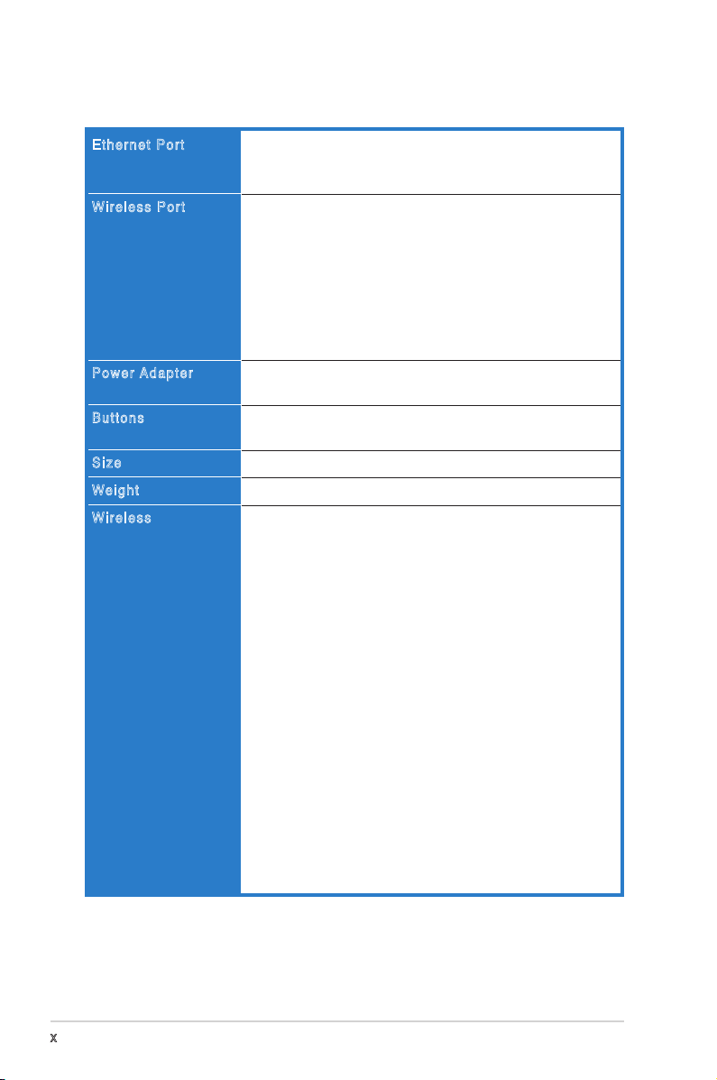
WL-330gE specications summary
Ethernet Port
Wireless Port
Power A d a p t e r
Buttons
Size
We i g h t
Wireless
LAN, 1 x RJ45 for 10/100 BaseT
Support Ethernet and 802.3 with max bit rate 10/100Mbps and
auto cross-over function (MDI-X)
Transmit Power: 11b 19+-1.5dBm, 11g 17+-1.5 dBm at
nominal temperature
Receiver Sensitivity: -95+-1dBm@1Mbps,
-85+-1dBm@11Mbps, -73+-1dBm@54Mbps
Antenna Gain in 1.25dBi
2 x internal IFA antenna
Range: Indoor 130ft (40m), semi-open 330ft (100m), outdoor
(LOS, Line of Sight) 1500ft (457m)
Range and throughput may vary by different environment.
AC input: 100V~240V (50~60Hz)
DC output: 5V with max 2A current
Reset Button: Push for 5 seconds to restore to factory default
settings
86mm x 62mm x 17mm (LxWxH)
62g (2.187oz, not including power adapter and cables)
802.11g/802.11b compliant
Operation Channels: Ch1~11 for N. America, Ch1~14 Japan,
Ch1~13 Europe (ETSI)
Wi-Fi Security: 64/128-bit WEP, WPA-PSK, WPA2-PSK, WPA Enterprise, WPA2-Enterprise, Radius with 802.1x
WMM: WMM (Wi-Fi Multimedia) support
MAC Access Control
RADIUS Setting: Required in Radius with 802.1x, WPA, WPA2
mode.
SSID Isolation: Support SSID hiding.Z
Wireless Separation: Prevent wireless clients from
communicating with each other.
Guest Account: Provide a second SSID for wireless access in
Gateway mode.
Infrastructure Mode
- AP Only
- WDS
- Hybrid
- Client
- URE
AfterBurner
BroadRange
(continued on the next page)
x
Page 11
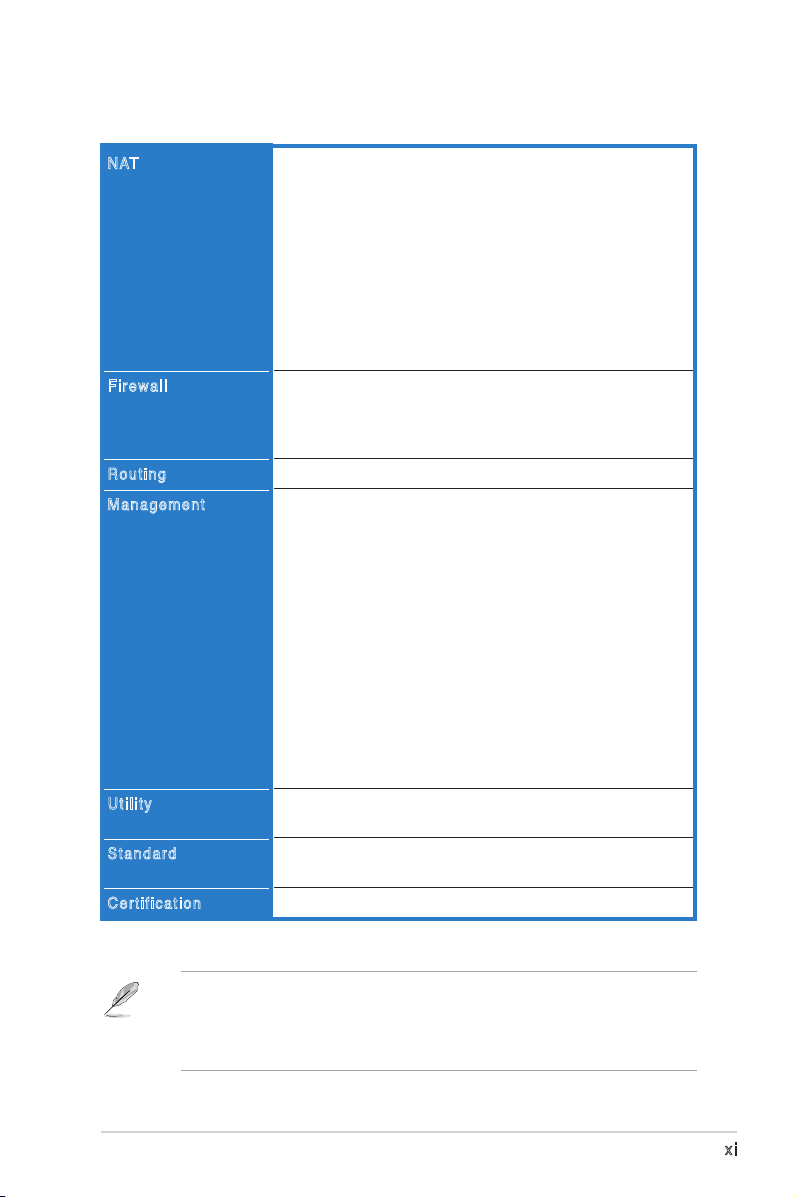
WL-330gE specications summary
NAT
Firewall
Routing
Management
Utility
Standard
Certification
Port Trigger
- Open certain TCP or UDP ports to communicate with the
computers connected to the ASUS WL-330gE.
Virtual Server
- Provides services like WWW, FTP by a server in the local
network accessible for outside users
Virtual DMZ
- Expose one computer to the Internet, so that all
the inbounds packets will be redirected to the exposed
computer.
ALG: FTP, SIP, VPN Passthrough-IPSec(1), PPTP/L2TP(4)
NAT and SPI (Stateful Packet Inspection) Firewall
Filtering
- Single Port and Port Range
- URL based
Static Route
Internet connection type: Automatic IP, Static IP, PPPoE
(MPPE supported), PPTP, Bigpond Service
Support UPnP IGD
DHCP Server
- Supports up to 253 IP addresses
- Changeable DHCP lease time, IP pool, domain name
DNS Proxy
NTP Client
DDNS: DynDNS, ZoneEdit, TZO
Web-based Administration
- Managed from LAN and Internet
- Password Setting
System Event Log
Firmware Upgrade: Web Interface, Bootloader
Save/Restore Conguration File
Device Discovery, supports Windows XP, 2000, Vista
Firmware Restoration, supports Windows XP, 2000, Vista
IEEE802.11g, IEEE802.11b, IEEE802.11d, IEEE802.3,
IEEE802.3, u, IEEE802.1X, WPA, WMM, IPv4, IPv6
WiFi, WPA, WMM, UPnP IGD
** GPL open source is included in the utility CD
• The ASUS Portable Wireless AP operating distance may be shorter
if there are walls, barriers, or interferences in the home layout or
operating environment.
• Specicationsaresubjecttochangewithoutpriornotice.
xi
Page 12

xii
Page 13

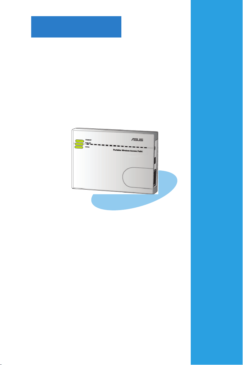
Chapter 1
This chapter describes the physical
features of the ASUS Portable
Wireless AP. This part presents the
package contents, LED indicators, and
recommended network settings.
Product introduction
Page 14

1.1 Welcome!
Thank you for choosing the ASUS Portable Wireless AP!
The ASUS Portable Wireless AP is a compact easy-to-install and use as access
point (AP), router, universal repeater, and Ethernet adapter in one. Implementing
the IEEE 802.11g standard for wireless LAN (WLAN) with BroadRange™ and125
HSM enhanced wireless technologies, the ASUS Portable Wireless AP is capable
of up to 125Mbps data transmission rate using the Direct Sequence Spread
Spectrum (DSSS) and the Octogonal Frequency Division Multiplexing (OFDM)
technologies. This AP is backward compatible with the earlier IEEE 802.11b
standard allowing seamless interfacing of both wireless LAN standards.
The ASUS Portable Wireless AP also supports several wireless network
conguration including AP, Infrastructure, and Ad-hoc modes giving you exibility
on your existing or future wireless network congurations.
To provide efcient security to your wireless communication, ASUS Portable
Wireless AP comes with a 64-bit/128-bit Wired Equivalent Privacy (WEP)
encryption and Wi-Fi Protected Access (WPA) features.
With these and many more, ASUS Portable Wireless AP is sure to keep you ahead
in the world of wireless computing.
1.2 Package contents
Check the following items in your ASUS Portable Wireless AP package. Contact
your retailer if any item is damaged or missing.
ASUS Portable Wireless AP (WL-330gE)
Universal power adapter and plug (100V ~ 240V)
USB power cord
RJ45 cable
Support CD (manual, utilities, GPL)
Quick Start Guide
Unless otherwise specied, the term “device” in this User Guide refers to the
ASUS Portable Wireless AP.
1-2 Chapter 1: Product introduction
Page 15
1.3 Features
The ASUS Portable Wireless AP employs the DSSS and OFDM technologies to
transmit and receive signals through radio waves on the 2.4 GHz band.
Here are other ASUS Portable Wireless AP features:
• Reliable data transfer rates of up to 135% of 54Mbps
• Secure data transmission via Wired Equivalent Privacy (WEP) and WiFi
Protected Access (WPA) encryptions
• Operating distance of up to 130ft (40m) indoors and 1000 ft (310m) outdoors
• Dual power mode (DC or USB bus-powered)
• Equipped with a mounting hook for wall installation
• Supports Infrastructure and Ad-hoc network types in Ethernet adapter mode
• Windows® 98SE/Me/2000/XP/Vista compatible
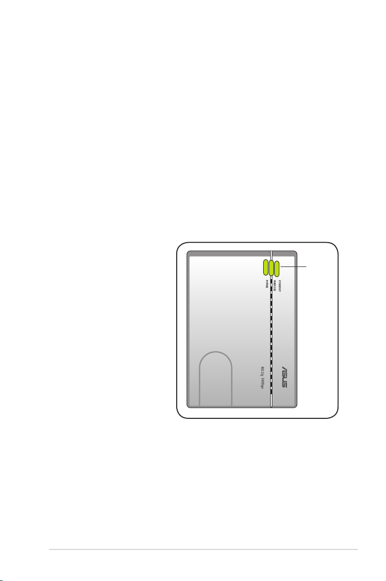
1. 3 .1 To p v ie w
LEDs. The ASUS Portable
Wireless AP comes with three LED
indicators (Ethernet, Wireless, and
Power). Refer to section 1.4 “LED
indicators” for details.
LEDs
1-3ASUS WL-330gE Portable Wireless A c c e s s P o i n t
Page 16
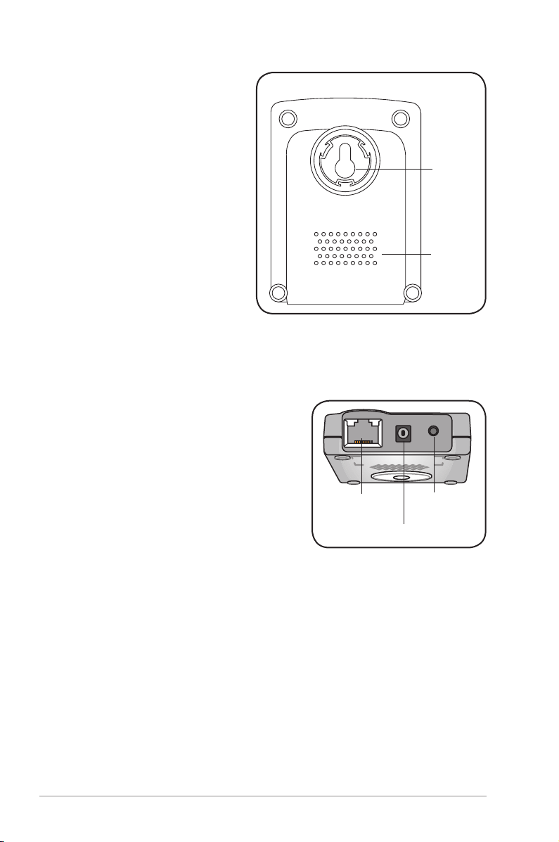
1. 3 .2 B ot t om v ie w
Mounting hook: Use the mounting
hook to install the device on
concrete or wooden surfaces
using a roundhead screw.
Air vents: These vents provide
ventilation to the device.
1. 3 .3 R ea r v ie w
Ethernet port: This port connects the supplied
RJ-45 plug and cable.
DC IN socket: This socket connects the power
adapter plug.
Reset button: Press this button for more than
ve seconds (in AP or Ethernet mode) to load
the default values. In Ethernet adapter mode,
press this button for less than ve seconds to
connect to the rst saved wireless connection
in the prole table. See page 3-15 for the reset
button function in Ethernet mode.
Ethernet port
DC IN socket
Mounting
hook
Air vents
Reset button
1-4 Chapter 1: Product introduction
Page 17
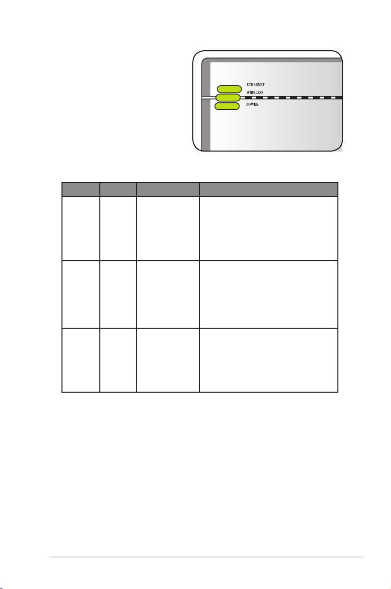
1.4 LED indicators
The ASUS Portable Wireless AP
comes with Ethernet, Wireless, and
Power LED indicators. Refer to the
table below for LED indicators.
LED Status Mode* Indication
Ethernet On
Router/AP/EA/
URE
The RJ-45 cable is connected and the
WL-330gE is connected to an Ethernet
network.
Off
Wireless On
Flashing
Off
Power On
Flashing
Off
Router/AP/URE
EA
EA
Router/AP/URE
EA
Router/AP/EA/
URE
Router/AP/EA/
URE
Router/AP/EA/
URE
The WL-330gE is off or is not connected
to an Ethernet network.
Associated.
Associated with an AP.
Associating.
Not associated.
Associated with an AP.
The WL-330gE is on and ready.
The WL-330gE is under “reset to default”
mode.
The device is off.
*Modes: AP: Access Point mode
EA: Ethernet adapter mode
URE: Universal repeater mode
1-5ASUS WL-330gE Portable Wireless A c c e s s P o i n t
Page 18
1.5 Recommended network settings
MODE
In the Quick Setup Wizard, you can only congure WEP for security (open
system). You can complete the share key and advanced security setup in the
Advanced Settings page.
The ASUS Portable Wireless AP can be congured in one of these modes:
1. Router/Gateway mode
2. Access Point (AP) mode
3. Ethernet Adapter mode
4. Universal Repeater mode
By default, the ASUS WL-330gE is set in the Router/Gateway mode.
1. 5 .1 Ro u te r/ Ga t ew ay m o de
In the Router/Gateway mode, the ASUS WL-330gE connects to the Internet via an
ADSL or a cable modem, and your network environment has multi-users using the
same IP to ISP.
˝
Wireless computer
WL-330gE
ADSL/Cable modem
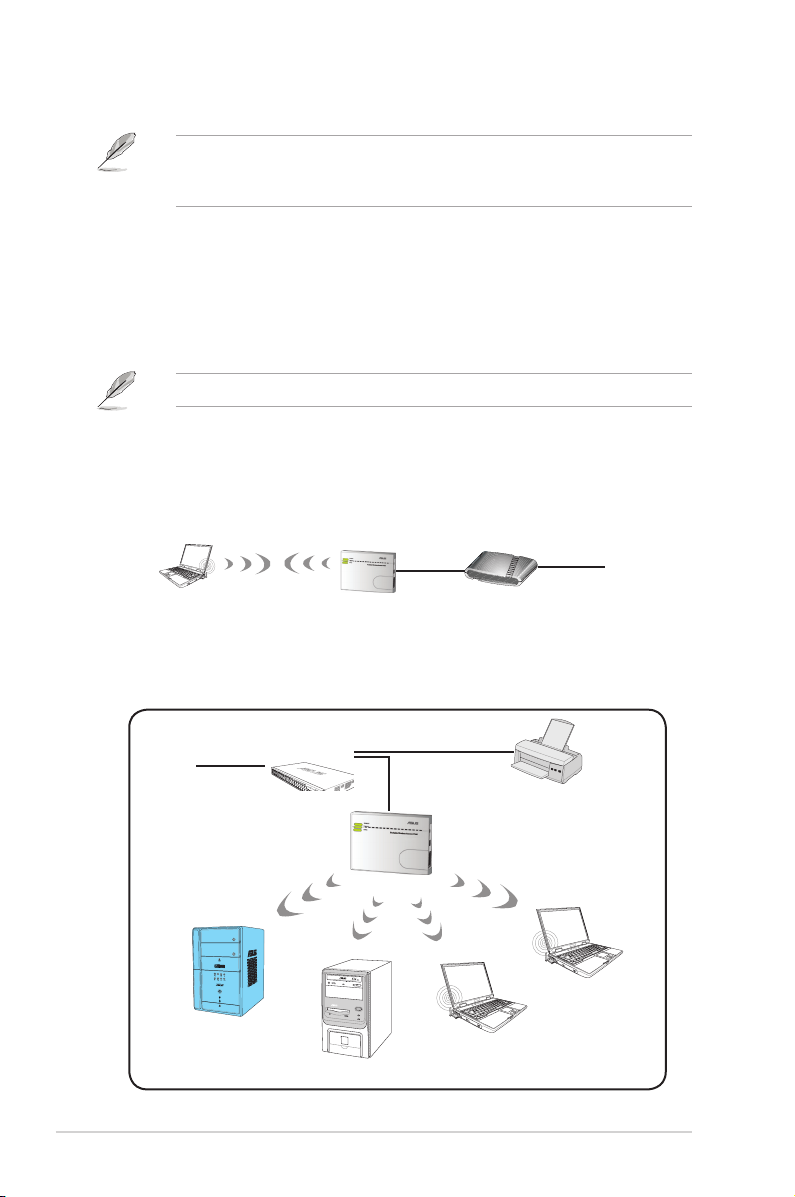
1. 5 .2 Ac c es s Po i nt ( AP ) m od e
When in access point (AP) mode the ASUS Portable Wireless AP connects WLANenabled computers and/or devices to a wired or wireless LAN.
Internet
˝
Internet
Client 1
1-6 Chapter 1: Product introduction
Hub
Client 2
Network Printer
WL-330gE
Client 4
Client 3
Page 19
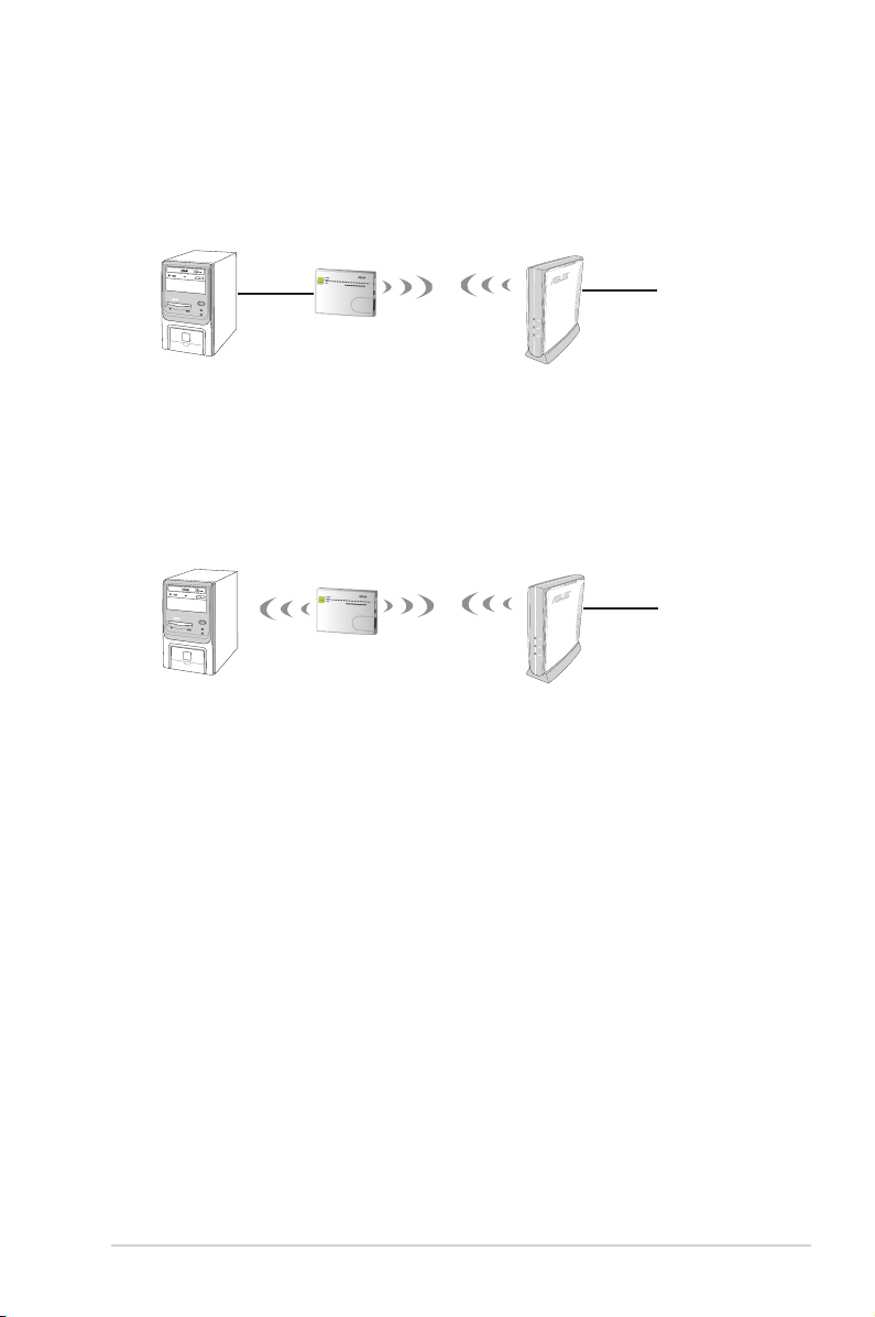
1. 5 .3 Et h er ne t Ad ap te r m od e
In the Ethernet Adapter mode, you can enable any Ethernet-capable device to go
wireless.
˝
WL-330gE
1. 5 .4 Re p ea te r m od e
In the Repeater mode, you can use the ASUS WL-330gE to connect with your root
router at home to extend your wireless coverage.
Internet
˝
WL-330gE
Internet
1-7ASUS WL-330gE Portable Wireless A c c e s s P o i n t
Page 20

1-8 Chapter 1: Product introduction
Page 21
Chapter 2
This chapter provides information
on how to install the ASUS Portable
Wireless AP.
Hardware installation
Page 22

2.1 System requirements
Before installing the ASUS Portable Wireless AP, make sure that your system/
network meets the following requirements:
• An Ethernet RJ-45 port (10Base-T/100Base-TX)
• At least one IEEE 802.11b/g device with wireless capability
• An installed TCP/IP and Internet browser
2.2 Device installation
Follow these instructions to install the ASUS Portable Wireless AP.
1. Install the device utilities from the support CD.
2. Connect the device to your computer, network hub, switch, or router.
2. 2 .1 B ef o re y ou pr oc ee d
Take note of the following guidelines before installing the ASUS Portable Wireless
AP.
• The length of the Ethernet cable that connects the device to the network (hub,
ADSL/cable modem, router, wall patch) must not exceed 100 meters.
• Place the device on a flat, stable surface as far from the ground as possible.
• Keep the device clear from metal obstructions and away from direct sunlight.
• Keep the device away from transformers, heavy-duty motors, fluorescent
lights, microwave ovens, refrigerators, and other industrial equipment to
prevent signal loss.
• Install the device in a central area to provide ideal coverage for all wireless
mobile devices.
• Install the device at least 20cms from a person to insure that the product is
operated in accordance with the RF Guidelines for Human Exposure adopted
by the Federal Communications Commission.
2-2 Chapter 2: Hardware installation
Page 23

2. 2 .2 U si n g DC p o we r
1
2
3
456
1. Insert one end of the supplied RJ-45 cable to the WL-330gE Ethernet port.
2. Insert the other end of the RJ-45 cable to a modem/switch, or Ethernet port,
depending in which mode you would like to set the WL-330gE.
3. Connect the power adapter plug to the WL-330gE DC-IN socket.
4. Connect the WL-330gE power adapter to a wall socket.
5. Connect the modem/switch power adapter plug to the DC-IN socket of the
device.
6. Connect the modem/switch power adapter to a wall socket.
Modem/Switch/PC
WL-330gE
Wall socket
2-3ASUS WL-330gE Portable Wireless A c c e s s P o i n t
Page 24

2. 2 . 3 U s i ng US B bu s p o w er
USB
1
2
3
4
5
6
1. Insert one end of the supplied RJ-45 cable to the WL-330gE Ethernet port.
2. Insert the other end of the RJ-45 cable to the Ethernet port on your computer,
notebook, modem or switch.
3. Insert one end of the supplied USB cable to the DC-IN socket of the device.
4. Insert the other end of the USB cable to any available USB port on your
computer, notebook, network hub, modem/switch, or router.
5. Turn on your computer/notebook, or connect the network hub, modem/switch,
or router power adapter to a wall socket.
6. Connect the power adapter of the network hub, computer/notebook, modem/
switch, or router to a wall socket.
Wall socket
Modem/Switch/PC
WL-330gE
2-4 Chapter 2: Hardware installation
Page 25

2.3 Placement
Wall m ou n ti ng
Aside from desktop placement,
you can install the ASUS Portable
Wireless AP vertically on a concrete
or wooden wall using the mounting
hook at the bottom side of the
device.
To mount the device on a concrete
or wooden wall:
1. Locate the mounting hook at the bottom of the device.
2. Select an ideal location for the device.
3. Tighten a round head screw on the concrete or wooden wall until only 1/4
inch is showing.
4. Latch the device into the screw until the device is in place.
Adjust the screw if you cannot latch the device or if the screw is too loose.
Mounting
hook
2.4 Operating range
The ASUS Portable Wireless AP range is dependent on the operating environment.
Every home or ofce layout varies in obstacles, barriers, or wall types which may
reect or absorb radio signals. For example, two 802.11b devices in an open space
may achieve an operating distance of up to 1000 meters, while the same devices
may only achieve up to 300 meters of range when used indoors.
The device automatically adjusts the data rate to maintain an operational wireless
connection. A wireless device that is close to an AP may operate at higher speeds
than a device far from the AP. You can congure the data rates that a device uses.
If you limit the range of data rates available to the ASUS Portable Wireless AP, you
may reduce the effective range of the wireless LAN coverage.
2-5ASUS WL-330gE Portable Wireless A c c e s s P o i n t
Page 26

2.5 Roaming information
If there are several ASUS Portable Wireless APs operating on a network, then a
wireless client (such as Centrino notebooks or wireless PDAs) may seamlessly
roam from one ASUS Portable Wireless AP to another. Each ASUS Portable
Wireless AP creates its own wireless cell or coverage area known as a Basic
Service Set (BSS). Any wireless client can communicate with a particular ASUS AP
if it is within that AP’s coverage area.
If the cells of multiple ASUS Pocket APs overlap, then the wireless client may
switch from one ASUS Portable Wireless AP to another. During the transfer from
one ASUS AP to another, the wireless mobile client maintains an uninterrupted
connection to the network. This is called roaming.
Multiple ASUS Pocket APs connected to a common Ethernet network form
an Extended Service Set (ESS). All members of an Extended Service Set are
congured with an ID, known as the SSID or ESSID. Wireless client must be
congured with the same SSID as that of the ASUS Pocket APs on the network
since it can only roam between ASUS Pocket APs sharing the same SSID.
Im p or ta nt no te s o n ro am i ng
• An ASUS WLAN card can only roam between APs of the same type.
• All ASUS Portable Wireless APs must have the same SSID.
• All computers with ASUS WLAN cards must have the same SSID as the
access points to enable roaming.
• If encryption is enabled, all ASUS APs and wireless clients must use the same
encryption to establish connection.
• ASUS Portable Wireless APs’ cells must overlap to provide an uninterrupted
connection for a roaming client.
• ASUS Portable Wireless APs using the same channel should be installed away
from each other to reduce potential interference.
• We strongly recommended that you perform a site survey using the ASUS
Portable Wireless AP utility to determine the best location for each wireless
device.
2-6 Chapter 2: Hardware installation
Page 27

Chapter 3
This chapter provides information on
how to congure the ASUS Portable
Wireless AP using the utilities available
from the support CD.
Utilities
Page 28

3.1 Installing the utilities
The support CD contains the utilities for conguring the ASUS Portable Wireless
AP. To install the ASUS WLAN Utilities in Microsoft® Windows, insert the support
CD in the CD drive. If Autorun is disabled, run setup.exe from the root directory of
the support CD.
(1) Click Install...Utilities.
(3) Click Next to accept the default
destination folder or click Browse to
specify another path.
(5) Click Finish when setup is
complete.
(2) Click Next.
(4) Click Next to accept the default
program folder or ent er another
name.
3-2 Chapter 3: Utilities
Page 29

3. 1 .1 La u nc hi ng th e ut i li ti es
To launch the utilities, click Start > All Programs > ASUS Utility from the
Windows desktop.
De v i ce Di s c ov e ry
Device Discovery is an ASUS WLAN utility which detects an ASUS 802.11g AP
device, and enables you to congure the device.
To launch the Device Discovery utility, click Start > All Programs > ASUS Utility
> Device Discovery.
3-3ASUS WL-330gE Portable Wireless A c c e s s P o i n t
Page 30

Fi r m wa r e R e st o ra t i on
The Firmware Restoration utility is an emergency rescue tool that can
automatically searches for an ASUS 802.11g AP that has failed during a rmware
upload, and re-upload a rmware that you specify. A failed rmware upgrade will
cause the ASUS 802.11g AP to enter a failure mode, waiting for the Firmware
Restoration utility to nd and upload a new rmware. The process takes about
three to four minutes.
This is not a rmware upgrade utility and cannot be used on a working ASUS
802.11g AP. Normal rmware upgrades must be done through the web
manager. Refer to Chapter 4: Web Conguration Manager for more details.
To launch the Firmware Restoration utility, click Start > All Programs > ASUS
Utility > Firmware Utility.
3-4 Chapter 3: Utilities
Page 31

Chapter 4
This chapter provides instructions
how to congure the ASUS Portable
Wireless AP using the Web
Conguration Manager.
Conguration
Page 32

4.1 Overview
The Web Conguration Manager is a web-based application which allows you to
congure the ASUS Portable Wireless AP using a web browser on your computer.
The following sections provide information on how to launch and use the Web
Conguration Manager.
4. 1 .1 Ad j us ti ng th e TC P /I P s et ti n gs
By default, the IP address of the ASUS Portable Wireless AP is 192.168.1.1, and
the Subnet Mask is 255.255.255.0. To access the conguration utility, assign a
different IP address to the network adapter where the ASUS Portable Wireless AP
is connected.
To adjust the TCP/IP settings of the network
adapter:
1. Right-click the My Network Places
icon in the Windows® desktop, then
select Properties from the pop-up
menu. The Network and Dial-up
Connections window appears.
2. Right-click the network adapter used
by the the ASUS Portable Wireless
AP, then select Properties from
the pop-up menu. The Local Area
Connection Properties window
appears.
4-2 Chapter 4: Configuration
Page 33

3. Double-click the Internet Protocol
(TCP/IP) item to display the Internet
Protocol (TCP/IP) Properties
window.
4. Check the Use the following IP
address option, then enter the IP
address for the network adapter. The
IP address must be 192.168.1.X.
(X can be any number between 2
and 254 that is not used by another
device.)
5. Set the Subnet Mask to
255.255.255.0. Click OK when
nished.
Changing the TCP/IP
settings may require system
restart. Switch on the WL330gE immediately after
rebooting.
4-3ASUS WL-330gE Portable Wireless A c c e s s P o i n t
Page 34

4.2 Operation modes
The ASUS WL-330gE is designed with four (4) selective operation modes: Router/
Gateway, Access Point (AP), Ethernet Adapter, and Universal Repeater.
4. 2 .1 Ro u te r/ Ga t ew ay m o de
In the Router/Gateway mode, the ASUS WL-330gE connects to the Internet via an
ADSL or a cable modem, and your network environment has multi-users using the
same IP to ISP.
˝
Wireless computer
In the Router/Gateway mode:
• NAT is enabled;
• WAN is allowed using PPPoE, DHCP client, or static IP; and
• UPnP and DDNS features, which are useful for home user, are supported.
To congure the ASUS WL-330gE in Router/Gateway mode:
1. In the Mode Quick Setup page, click the Gateway tab. The Gateway page is
displayed.
WL-330gE
ADSL/Cable modem
Internet
4-4 Chapter 4: Configuration
Page 35

2. Specify an SSID (Service Set Identier), which is a unique identier attached
to packets sent over WLAN.
3. Select a security level to enable encryption methods:
Low(None): No security level.
Medium (WEP-64bits):
Medium (WEP-128 bits)
High (WPA-PSK/WPA-PSK)
4. Click Finish to save the conguration.
You can set up the advanced functions. Refer to Advance Settings section on
page 4-9 for more details.
4. 2 .2 Ac c es s Po i nt ( AP ) m od e
In the Access Point (AP) mode, you can connect the Ethernet port and your
wireless devices into the same local area network (LAN).
Wireless computer
WL-330gE
To congure the ASUS WL-330gE in Access Point/AP mode:
1. In the Mode Quick Setup page, click the AP tab. The Access Point (AP) page
is displayed.
4-5ASUS WL-330gE Portable Wireless A c c e s s P o i n t
Page 36

2. Specify an SSID (Service Set Identier), which is a unique identier attached
to packets sent over WLAN.
3. Select a security level to enable encryption methods:
Low(None): No security level.
Medium (WEP-64bits):
Medium (WEP-128 bits)
High (WPA-PSK/WPA-PSK)
4. Click Finish to save the conguration.
You can set up the advanced functions. Refer to Advance Settings section on
page 4-9 for more details.
4-6 Chapter 4: Configuration
Page 37

4. 2 .3 Et h er ne t Ad ap te r m od e
In the Ethernet Adapter mode, you can enable any Ethernet-capable device to go
wireless.
˝
WL-330gE
To congure the ASUS WL-330gE in Ethernet Adapter mode:
1. In the Mode Quick Setup page, click the Adapter tab. The Adapter page is
displayed.
Internet
2. From the available list of devices in LAN, select the device you want to
connect to.
3. Click Connect.
You can set up the advanced functions. Refer to Advance Settings section on
page 4-9 for more details.
4-7ASUS WL-330gE Portable Wireless A c c e s s P o i n t
Page 38

4. 2 .4 Re p ea te r m od e
In the Repeater mode, you can use the ASUS WL-330gE to connect with your root
router at home to extend your wireless coverage.
˝
WL-330gE
To congure the ASUS WL-330gE in Repeater mode:
1. In the Mode Quick Setup page, click the Repeater tab. The Repeater page is
displayed.
Internet
2. From the available list of devices in LAN, select the device you want to
connect to.
3. Click Connect.
You can set up the advanced functions. Refer to Advance Settings section on
page 4-9 for more details.
4-8 Chapter 4: Configuration
Page 39

4.3 Advance settings
When you click the link Advance Setting from any of the modes in the Mode
Quick Setup page, the screen shown below is displayed.
4. 3 .1 Na v ig at io n m en u
The navigation menu, located at the left of the screen,
contains the main menu and sub-menu items.
Use the navigation menu to congure the various features
of the ASUS WL-330gE.
4-9ASUS WL-330gE Portable Wireless A c c e s s P o i n t
Page 40

4. 3 .2 Qu i ck S et u p in AP m od e
When you click the link Advance Setting from any of the modes in the Mode
Quick Setup page, the default page is the Access Point (AP) mode.
1. Click Next to enter the Quick Setup page. Follow the instructions to set up
the ASUS Access Point.
2 S e t mo d e t o A P o r
WDS(Bridge), Station(Client) or
URE(Repeater).
3. Setting up your wireless
interface. Specify to your
wireless router an SSID (Service
Set Identier), which is a unique
identier attached to packets
sent over WLAN. This identier
emulates a password when a
device attempts to communicate with your wireless router via WLAN.
If you want to protect transmitted data, proceed to steps 4 and 5. Otherwise,
go to step 6.
4. Select a Security Level to enable
encryption methods.
Medium: Only users with the
same WEP key settings can
connect to your wireless router
and transmit data using 64bits or
128bits WEP key encryption.
4-10 Chapter 4: Configuration
Page 41

High: Only users with the same WPA pre-shared key settings can connect to
your wireless router and transmit data using TKIP encryption.
5. Input one set of WEP keys in the WEP Key elds (10 hexadecimal digits for
WEP 64bits, 26 hexadecimal digits for WEP 128bits), and then select from
Key Index accordingly. You can also let the system generate the keys by
inputting a Passphrase. Record the Passphrase and the WEP keys in your
notebook, then select from Key Index accordingly. Click Finish to enable your
setting. For example, if we input 11111 as the Passphrase, the WEP Keys are
generated automatically.
6. Click Save&Restart to restart the wireless router and activate the new
settings.
4. 3 .3 Qu i ck S et u p in H o me G at e wa y Mo d e
To start quick setup in Gateway mode, click Apply to enter the “Quick Setup” page.
To set up the ASUS 802.11g AP:
1. Click System Setup -> Operation Mode -> Home Gateway. In the Home
Gateway mode, you will be able to connect to the Internet through ADSL or
cable modem.
2. Click Apply to enter the
Gateway mode.
3. Select your time zone or the
closest region. Click Next to
continue.
4. The ASUS 802.11g AP supports ve types of ISP services— cable, ADSL
(PPPoE, PPTP, static IP address), and Telstra BigPond. Since each service
has its own protocols and standards, therefore, during the setup process,
there are different identity settings demanded by the Access Point. Select the
correct connection type and click Next to continue.
4-11A S U S W L - 3 3 0 g E P o r t a b l e W i r e l e s s Access Point
Page 42

Ca b l e U se r
If you are receiving services from cable or other ISP assigning IP addresses
automatically, select Cable Modem or other connection that gets IP automatically.
If you are using cable services and your ISP have provided you with the hostname,
the MAC address, and the heartbeat server, ll these information into the boxes on
the setting page. If not, click Next to skip this step.
PP P o E U se r
If you are a PPPoE service user, select the second line. You would be required to
input the username and password provided by your ISP.
4-12 Chapter 4: Configuration
Page 43

PP T P Us e r
If you are using PPTP services, you would be asked to input the username,
password, as well as the IP address provided by your ISP.
St a t ic IP U s er
If you are using ADSL or other connection type that uses static IP addresses,
please select the fourth line, then input the IP address, subnet mask, and default
gateway provided by your ISP. You could choose to specify certain DNS servers, or
select to get DNS automatically.
4-13ASUS WL-330gE Portable Wireless A c c e s s P o i n t
Page 44

5. Setting up your wireless interface. To set up your wireless interface, follow the
same instructions from 3 to 5 as above Congurating Wireless Interface in
Access Point mode on page 26 and page27. You can change to AP or WDS
(Bridge), Station (Client), or URE (Repeater) accordingly. Click Save&Restart
to restart the wireless router and activate the new settings.
4. 3 .4 Wir el es s
Click an item on the menu to reveal a submenu. Follow the
instructions to set up the ASUS 802.11g AP. Tips are displayed
when you move your cursor over an item.
In t e rf a ce
SSID
The SSID is an identication string of up to 32 ASCII characters that differentiate
the ASUS 802.11g AP from other manufacturers. The SSID is also referred to as
the “ESSID” or “Extended Service Set ID.” You can use the default SSID and radio
channel unless more than one ASUS 802.11g AP is deployed in the same area.
In that case, you should use a different SSID and a radio channel for each ASUS
802.11g AP. All ASUS Wireless APs/Routers and ASUS 802.11g/802.11b WLAN
client adapters must have the same SSID to allow a wireless mobile client to roam.
By default, the SSID is set to “default”.
4-14 Chapter 4: Configuration
Page 45

Channel
The 802.11g and 802.11b specications supports up to 14 overlapping channels
for radio communication. To minimize interference, congure each ASUS 802.11g
AP to be non-overlapping; select Auto from the Channel drop-down list to enable
the system to select a clear channel during boot up as your operating channel.
Based on your site survey of your network facility, make sure that all the ASUS
802.11g APs sharing the same channel, or channels in close number frequency,
are located far from each other as possible. You can use the site survey utility from
the support CD. Refer to 3.7.2 Site Survey (AP SCAN) for details.
Wireless Mode
This eld indicates the 802.11g interface mode. Selecting “Auto” allows 802.11g
and 802.11b clients to connect to the ASUS 802.11g AP. Selecting “54g Only”
maximizes performance, but prevents 802.11b clients from connecting to the
ASUS 802.11g AP. If “54g Protection” is checked, GMode protection of 11g trafc is
enabled automatically in the presence of 11b trafc.
Authentication Method
This eld enables you to set different authentication methods which determine
different encryption schemes. The relationships among Authentication Method,
WPA Encryption, WPA Pre-Shared Key, WEP Encryption, Passphrase, and WEP
Keys are listed in the following table. If all your clients support WPA, using “WPAPSK” is recommended for better security.
Aut hent icati on
Met hod
Open or shared key None
Shared key WEP (64 bits)
WPA-PSK TKIP only
WPA TKIP only
Radius with 802.1x Auto
WPA/WE P
Enc rypt ion
WEP (64 bits)
WEP (128 bits)
WEP (128 bits)
AES only
AES only
WEP (64 bits)
WEP (128 bits)
WPA P r e -Sha red
Key Pas sphra se
Not required
1-64 characters
1-64 characters
1-64 characters
1-64 characters
8-63 characters
8-63 characters
Not required
Not required
Not required
1-64 characters
1-64 characters
WEP K e y 1- 4
Not required
10 hex
26 hex
10 hex
26 hex
Not required
Not required
Not required
Not required
Not required
10 hex
26 hex
4-15ASUS WL-330gE Portable Wireless A c c e s s P o i n t
Page 46

WPA Encryption
When “WPA-PSK” authentication method is used, the newly proposed TKIP
(Temporal Key Integrity Protocol) or AES encryption schemes are applied.
WPA Pre-Shared Key
Select “TKIP” or “AES” in the WPA Encryption, this eld is used as a password to
begin the encryption process. 8 to 63 characters are required.
WEP Encryption
When “Open or Shared Key”, “Shared Key” or “Radius with 802.1x” authentication
methods are selected, traditional WEP encrption is applied.
When “WPA” or “WPA-PSK” authentication methods are selected, you still
can set WEP encryption for those clients that do not support WPA/WPA-PSK.
Please note that Key Index for WEP key is limited to 2 or 3 when both WPA and
WEP encryption are supported at the same time.
64/128-bit versus 40/104-bit
The following section explains low-level (64-bit) and high-level (128-bit) WEP
Encryption schemes:
64-bit WEP Encryption
64-bit WEP and 40-bit WEP are the same encryption methods and can
interoperate in a wireless network. This level of WEP encryption uses a 40-bit (10
Hex character) encryption scheme as a secret key, which is set by the user, and a
24-bit “Initialization Vector” scheme, which is not under user control.
Together these two schemes make a 64-bit (40 + 24) encryption scheme. Some
vendors refer to this level of WEP as 40-bit and others refer to this as 64-bit. ASUS
WLAN products use the term 64-bit when referring to this lower level of encryption.
128-bit WEP Encryption
104-bit WEP and 128-bit WEP are the same encryption method and can
interoperate on a wireless network. This level of WEP encryption uses a 104-bit
(26 Hex character) encryption scheme as a secret key which is set by the user,
and a 24-bit “Initialization Vector”, which is not under user control.
Together these two schemes make a 128-bit (104 + 24) encryption scheme. Some
vendors refer to this level of WEP as 104-bit and others refer to this as 128-bit.
ASUS WLAN products use the term 128-bit when referring to this higher level of
encryption.
4-16 Chapter 4: Configuration
Page 47

Passphrase
Select “WEP-64bits” or “WEP-128bits” in the Encryption eld, and the Access
Point generates four WEP keys automatically. A combination of up to 64 letters,
numbers, or symbols is required. Alternatively, leave this eld blank and type in
four WEP keys manually.
WEP-64bit key: 10 hexadecimal digits (0~9, a~f, and A~F)
WEP-128bit key: 26 hexadecimal digits (0~9, a~f, and A~F)
The ASUS WLAN family of products uses the same algorithm to generate WEP
keys. It eliminates the need for users to remember passwords and maintains
compatibility between products. But, this method to generate WEP keys is not
as secure as manual assignment.
WEP Key
You can set a maximum of four WEP keys. A WEP key is either 10 or 26
hexadecimal digits (0~9, a~f, and A~F) based on whether you select 64-bits
or 128-bits in the WEP pull-down menu. The ASUS 802.11g AP and ALL of its
wireless clients MUST have at least the same default key.
Key Index
The Default Key eld lets you specify which of the four encryption keys to use to
transmit data on your wireless LAN. As long as the ASUS 802.11g AP or wireless
mobile client with which you are communicating has the same key in the same
position, you can use any of the keys as the default key.
If the ASUS 802.11g AP and ALL of its wireless clients use the same four WEP
keys, select “key rotation” to maximize security. Otherwise, choose one key in
common as the default key.
Network Rotation Key Interval
This eld species the time interval (in seconds) after which a WPA group key is
changed. Enter ‘0’ (zero) to indicate that a periodic key-change is not required.
4-17ASUS WL-330gE Portable Wireless A c c e s s P o i n t
Page 48

Si t e S u rv e y ( A P S C A N)
Site Survey helps the Access Point associate appropriate AP while either in Station
(Client) or URE (Repeater) mode. Make sure that the Access Point in Client or
URE mode. Click “AP SCAN” button in Wireless -> Interface and a new window
opens. AP Scan will collect complete AP around information including MAC, SSID,
Security, Channel and RSSI (AP wireless signal strength) value.
Ac c e ss Co n t ro l
Pull down menu items:
Disable (no info required)
Accept (need to input information)
Reject (need to input information)
For security, the ASUS 802.11g AP allows you to accept or reject wireless mobile
clients.
The default setting of “Disable” allows any wireless mobile client to connect.
“Accept” only allows those entered into this page to connect. “Reject” prevents
those entered into this page from connecting.
4-18 Chapter 4: Configuration
Page 49

Adding a MAC Address
The Known Client List collects MAC addresses of known clients, associated to the AP.
To add a MAC address to the Access Control List, simply select MAC address from
the list then click “Copy” button.
Note: Click the “Finish” button to save your new settings and restart the ASUS
802.11g AP or click “Save” and restart later.
RA D I US Se t t in g
This section allows you to set up additional parameters for connection with
RADIUS Server. It is required while you select “Authentication Method” as “WPA”
or “Radius with 802.1x” in “Wireless – Interface”.
Server IP Address - This eld species the IP address of the RADIUS server to
use for 802.1X wireless authentication and dynamic WEP key derivation.
Server Port - This eld species the UDP port number used by the RADIUS
server.
Connection Secret - This eld species the password used to initialize a RADIUS
connection.
Note: Click the “Finish” button to save your new settings and restart the ASUS
802.11g AP or click “Save” and restart later.
4-19ASUS WL-330gE Portable Wireless A c c e s s P o i n t
Page 50

Gu e s t Ac c ou n t
This section allows you to create a guest account for wireless access. Select Yes
in the Enable Guest Account option.
Ad v a nc e d
This section allows you to set up
additional parameters for the wireless
router function. We recommend that you
use the default values for all items in this
window.
You may also setup operation modes
(AP or WDS, Adapter, or Repeater) in
this window aside from the Quick Setup
screen.
Hide SSID -“No” is the default option so that wireless mobile users can see your
ASUS 802.11g AP’s SSID and associate with your Access Point. If you select
“Yes”, your ASUS 802.11g AP will not show in site surveys by wireless mobile
clients and they will have to manually enter your ASUS 802.11g AP’s SSID. To
restrict access to your ASUS 802.11g AP , select “Yes”. For security reasons,
change the SSID other than the default SSID.
4-20 Chapter 4: Configuration
Page 51

Set AP Isolated - Selecting Yes to prevent wireless client from communicating with
each other.
Data Rate (Mbps) - This eld allows you to specify the transmission rate. Leave on
“Auto” to maximize performance versus distance.
Basic Rate Set - This eld indicates the basic rates that wireless clients must
support. Use “1 & 2 Mbps” only when backward compatibility is needed for some
older wireless LAN cards with a maximum bit rate of 2Mbps.
Fragmentation Threshold (256-2346) – Fragmentation is used to divide
802.11 frames into smaller pieces (fragments) that are sent separately to the
destination. Set a specic packet size threshold to enable fragmentation. If there
is an excessive number of collisions on the WLAN, experiment with different
fragmentation values to increase the reliability of frame transmissions. The default
value (2346) is recommended for normal use.
RTS Threshold (0-2347) – The RTS/CTS (Request to Send/Clear to Send)
function is used to minimize collisions among wireless stations. When
RTS/CTS is enabled, the router refrains from sending a data frame until another
RTS/CTS handshake is completed. Set a specic packet size threshold to enable
RTS/CTS. The default value (2347) is recommended.
DTIM Interval (1-255) – DTIM (Delivery Trafc Indication Message) is a wireless
message used to inform clients in Power Saving Mode when the system should
wake up to receive broadcast and multicast messages. Type the time interval in
which the system will broadcast a DTIM for clients in Power Saving Mode. The
default value (3) is recommended
Beacon Interval (1-65535) – This eld indicates the time interval in milliseconds
that a system broadcast packet, or beacon, is sent to synchronize the wireless
network. The default value (100 milliseconds) is recommended.
Enable Frame Bursting? – This eld allows you to enable frame-bursting mode to
improve performance with wireless clients that also support frame-bursting.
Radio Power – Radio Power can be set between 1 to 84 but the default value is
recommended.
Enable WMM – This eld allows you to enable WMM to improve multimedia
transmission
Enable WMM No-Acknowledgement – This eld allows you to enable WMM No-
Acknowledgement
4-21ASUS WL-330gE Portable Wireless A c c e s s P o i n t
Page 52

Mode – This eld allows you set up different operation modes(AP or WDS,
Adapter, or Repeater) either in AP mode or Gateway mode.
URE – This section allows you set up parameters for URE. This section only works
while in URE mode.
SSID – This is the SSID of root AP. The ASUS 802.11g AP can repeat the signal
and boost the signal coverage while setting in URE mode.
Other security parameters settings are the same as those in Wireless ->
Interface.
4. 3 .5 IP Co n fi g
Click this item on the menu to reveal a sub menu. Follow the
instructions to setup the ASUS 802.11g AP. Tips are given when
you move your cursor over each item.
4-22 Chapter 4: Configuration
Page 53

WA N & LA N
The ASUS WL-330gE supports several connection types to WAN. You can select
the WAN Connection Type from the dropdown list. The setting elds will vary
based on the connection type you have chosen.
DH C P Se r ve r
The ASUS WL-330gE supports up to 253 IP addresses for your local network.
The IP address of a local machine can be manually assigned by the network
administrator or obtained automatically from WL-330gE if the DHCP server is
enabled.
4-23ASUS WL-330gE Portable Wireless A c c e s s P o i n t
Page 54

Ro u t e
This function allows you to add routing rules into the ASUS WL-330gE. It is useful
if you connect several routers behind WL-330gE to share the same connection to
the Internet.
Mi s c el l an e o us
This function allows you to congure other features such as enabling UPnP, and
congure the DDNS setting.
4-24 Chapter 4: Configuration
Page 55

4. 3 .6 NAT S et ti n g
Po r t Trig g er
This function allows you to open certain TCP or UDP ports to communicate with
the computers connected to the ASUS WL-330gE. This is done by dening trigger
ports and incoming ports. When the trigger port is detected, the inbound packets to
the specied incoming port numbers are redirected to your computer.
Vir t u al Se r v er
Virtual Server allows you to make services, like WWW, FTP, provided by a server in
your local network accessible for outside users.
4-25ASUS WL-330gE Portable Wireless A c c e s s P o i n t
Page 56

Vir t u al DM Z
This function allows you to expose a computer to the Internet, so that all inbound
trafcs will be redirected to the computer you set. It is useful when you run some
applications that use uncertain incoming ports.
Use this function carefully.
4. 3 .7 In t er ne t F ir ew al l
Ba s i c C on f i g
This function allows you to congure the basic security for your WL-330gE and
other devices connected to it.
If you want to lter out specic packets, refer to the next section WAN & LAN
Filter.
4-26 Chapter 4: Configuration
Page 57

WA N & LA N Fi l te r
This function allows you to block specic packets between LAN and WAN.
First, you should dene the date and time that ltering will take place. Next, you
should select the default action for lter in both directions and insert rules for any
exceptions.
UR L F il t er
This function allows you to block specic URL access from your local network.
4-27ASUS WL-330gE Portable Wireless A c c e s s P o i n t
Page 58

4. 3 .8 Sy s te m Se t up
Click this item on the menu to reveal a sub menu. Follow the
instructions to setup the ASUS 802.11g AP. Tips are given when
you move your cursor over each item.
Gl o b al Se t t in g s
This function allows you to change your password and to select your preferred
language.
4-28 Chapter 4: Configuration
Page 59

Op e r at i on M od e
This function allows you to select the operation mode for the ASUS WL-330gE.
You can select either Home Gateway or Access Point mode.
Home Gateway
In this mode, the ASUS WL-330gE is connected to the Internet via ADSL or a cable
modem, and multi-users share the same IP to ISP in your network environment.
In this mode, NAT is enabled; WAN connection is enabled using PPoE, DHCP
client, or static IP; and UPnP and DDNS are supported.
Access Point
In this mode, the Ethernet port and the wireless devices are set in the same local
area network (LAN).
In this mode, NAT is disabled; and wireless devices and the LAN port of WL-330gE
are bridged together.
4-29ASUS WL-330gE Portable Wireless A c c e s s P o i n t
Page 60

Fi r m wa r e U p gr a de
This page reports the Flash Code (Firmware) version installed in the ASUS
802.11g AP. Periodically, a new Flash Code is available for the ASUS 802.11g
APs on ASUS’s Web site. You can update the ASUS 802.11g AP’s Flash Code
using the Firmware Upgrade page under the Advanced Setup menu of the Web
Manager. If you are experiencing a problem with your ASUS WLAN equipment, a
Technical Support representative may ask you to give your device’s Flash Code
(Firmware) version.
Note: The rmware upgrade takes approximately 60 to 90 seconds. When the
rmware upgrade is completed, you will be directed to the home page.
4-30 Chapter 4: Configuration
Page 61

Se t t in g M a n ag e me n t
This function allows you to save current settings to a le, or load settings from a
le.
Save As a File
Right-click on HERE link and select Save As... to save current setting into a le.
Note: When current settings are saved to le, it will be saved to ash as well.
Load From a File
Specify the path and name of the downloaded le in the New Setting File below.
Then, click Upload. The upload process takes few minutes and then the system
will reboot.
New Setting File
Click Browse to locate the le.
4-31ASUS WL-330gE Portable Wireless A c c e s s P o i n t
Page 62

Fa c t or y D e f au l t
Restoring Factory Default Settings
Web Manager
You can reset all settings to their factory default settings through the web manager
using the “Factory Default” page in “Advanced Setup”. Click the Restore button
and wait about 30 seconds before trying to access the ASUS 802.11g AP.
Hardware
You can reset all settings to their factory defaults manually by pushing the “Reset”
button of the ASUS 802.11g AP while it is ON. See page 21. Push the “Reset”
button with a pen or a paper clip for about 5 seconds or until the power LED starts
blinking.
Note: You will be notied when factory default settings are restored while using
the web manager.
4-32 Chapter 4: Configuration
Page 63

4. 3 .9 St a tu s & L og
Click this item on the menu to reveal a sub menu. Follow the
instructions to setup the ASUS 802.11g AP. Tips are given when
you move your cursor over each item.
St a t us
Wir e le s s
Sy s t em Up T i me
It shows how long the ASUS 802.11g AP has been running since the last bootup.
4-33ASUS WL-330gE Portable Wireless A c c e s s P o i n t
Page 64

4-34 Chapter 4: Configuration
Page 65

Chapter 5
This chapter provides instructions
on how to use the ASUS Portable
Wireless AP on various network
setups.
Using the device
Page 66

5.1 Using the device in a local network
You can use the WL-330gE to connect a wireless LAN-enabled computer to a local
network with or without a DHCP server.
To connect a wireless LAN-enabled computer to a local network:
1. Switch the WL-330gE to AP mode. (Default SSID: AP_xxxxxx), then turn on
the device.
2. Connect one end of the supplied RJ-45 cable to the Ethernet port of the
device and the other end to the Ethernet port of the local network.
3. Use the wireless LAN adapter software in the wireless LAN-enabled
computer to perform a Site Survey. Make sure the computer’s wireless LAN
adapter is set to Infrastructure mode.
4. Establish connection with the WL-330gE.
5. Set the IP conguration of the computer to establish connection to the local
network. Verify your connection.
Use the Wireless Setting Utility to change the WL-330gE SSID or encryption
settings.
5.2 Replacing the computer Ethernet cables
You can use the WL-330gE to replace your wireless LAN-enabled computer cable
connection to an ADSL or cable modem.
To do this:
1. Switch the WL-330gE to AP mode. (Default SSID: AP_xxxxxx), then turn on the
device.
2. Connect one end of the supplied RJ-45 cable to the Ethernet port of the device
and the other end to the Ethernet port of the ADSL or cable modem.
3. Use the wireless LAN adapter software in the wireless LAN-enabled computer
to perform a Site Survey. Make sure the computer’s wireless LAN adapter is
set to Infrastructure mode.
4. Establish connection with the WL-330gE.
5. Set the IP configuration of the computer to establish connection to the local
network. Verify your connection.
5-2 Chapter 5: Using the device
Page 67

5.3 Replacing the cable connections of other
devices
You can also use the WL-330gE to replace your Xbox, PlayStation
box network cable connection.
To do this:
1. Switch the WL-330gE to Ethernet adapter mode using the mode switch.
(Default SSID: ANY)
2. Place the WL-330gE nearest the AP you wish to connect, then turn on the
device.
3. Connect one end of the supplied RJ-45 cable to the Ethernet port of the device
and the other end to the Xbox, PlayStation® 2, or set-top box Ethernet port.
4. Set the IP address of the Xbox, PlayStation® 2, or set-top box toestablish
connection to the local network. Verify your connection.
Make sure the WL-330gE MAC cloning feature is enabled when using the
device in this setup. Use the Wireless Setting Utility to enable MAC cloning. See
page 3-24 for details on MAC cloning.
®
2, orset-top
5.4 Sharing Internet connection with other
computers
Refer to the typical network conguration below and a table on the next page for
information on Internet connection sharing with other computers in your ofce or
home network.
˝
ADSL/Cable modem WL-330gE
Use the mode switch to set the WL-330gE to AP mode before sharing an
Internet connection with other computers in your network.
Wireless computerInternet
5-3ASUS WL-330gE Portable Wireless A c c e s s P o i n t
Page 68

Ta ble 4-1: Inte rnet conn ecti on sh arin g mat rix
If your Inte rnet
con nect ion i s
xDSL1 with dynamic IP
(PPPoE2 account)
The n se t the IP o f othe r
com pute r(s)
ISP automatically assigns the
IP (using PPPoE dial-up)
Num ber of al lowe d
Int erne t con nect ions
Depends on the Internet
Service Provider (ISP)
xDSL with static IP to the provided static IP Depends on the Internet
Service Provider (ISP)
xDSL/Cable with a router and
enable DHCP3 server
1
xDS L - ADSL (Asy mmetr ic D igita l Su bscri ber Line) or DSL ( D i git al Su bscri b e r Line )
2
PPP oE - Poin t-to -Poin t ov er Et herne t
3
DHC P - Dyna mic Host Conf igura tion Prot ocol
The DHCP server automatically
assigns the IP
Depends on the DHCP server,
usually about 253
5-4 Chapter 5: Using the device
Page 69

Appendix
The Appendix features a
troubleshooting guide for solving
common problems you may encounter
when using the ASUS Portable
Wireless AP.
Troubleshooting
Page 70

This troubleshooting guide provides solutions to some common problems
that you may encounter while installing or using the ASUS Portable Wireless
AP. These problems require simple troubleshooting that you can perform by
yourself. Contact the ASUS Technical Support if you encounter problems not
mentioned in this section.
Pro blem Act ion
The ASUS Portable Wireless
AP does not power up.
Other devices cannot
communicate with the ASUS
Portable Wireless AP through
a wired network connection.
My ASUS WLAN card can
not associate with the ASUS
Portable Wireless AP.
The throughput seems slow. Avoid placing the device behind a metal object. Clear obstacles
• Use a test meter to measure the voltage output of the power source
through the power plug.
• Check if the power plug is properly connected to the device.
• Verify your network conguration to ensure that there is no IP
address duplication. Turn off the device in question, then ping the
assigned IP address of the device. Make sure no other device
responds to that address.
• Check if the cables have the proper pin outs and connectors. You
may also use another LAN cable.
• Make sure the hub, switch, or computer connected to the ASUS
Portable Wireless AP supports 10Mbps or 100Mbps speed.
Do this by check the ASUS Portable Wireless AP and the Hub LEDs.
When you connect the ASUS Portable Wireless AP to a 10/100 Mbps
hub, both the Hub LED and the ASUS Portable Wireless AP Ethernet
LEDs should light up.
• Make sure your WLAN card has the same specications as the
ASUS Portable Wireless AP (IEEE 802.11b/g).
Minimize the distance between the devices. The ASUS WLAN card
may be out of range of the ASUS Portable Wireless AP.
• Check if the ASUS Portable Wireless AP and the ASUS WLAN card
have the same SSID.
• When encryption is enabled, check if the ASUS Portable Wireless
AP and the ASUS WLAN card have the same encryption settings.
• Check if the Wireless LED of the ASUS Portable Wireless AP is on.
• When the Access Control table is enabled, check if the MAC
address of the ASUS WLAN card is included in the Access Control
table.
• Check if the ASUS Portable Wireless AP is in “Access Point” mode.
between the AP and the device. Try moving the client closer to the
ASUS Portable Wireless AP and check if the throughput increases.
Consider adding a second ASUS Portable Wireless AP to implement
roaming.
A-2 Appendix: Tr o u b l e s h o o t i n g
Page 71

Pro blem Act ion
I can not access the ASUS
Portable Wireless AP web
conguration page.
Where can I get a rmware le
to upgrade the ASUS Portable
Wireless AP?
The ASUS Portable Wireless
AP Power LED continuously
blinks for more than a minute.
A wireless client wants to
connect to the ASUS Portable
Wireless AP but can not get
the correct IP from the DHCP
server. (The ASUS Portable
Wireless AP has an enabled
DHCP.)
To access the ASUS Portable Wireless AP web conguration page,
your computer must have the same subnet as that of the ASUS
Pocket Wireless AP.
Adjust your network if your computer’s subnet does not match
that of the ASUS Portable Wireless AP.
The default IP address of the ASUS Portable Wireless AP is
“192.168.1.1”. In special cases, when the ASUS Portable Wireless
AP in Ethernet adapter mode joins an AP network with the same IP
address, reset the ASUS Portable Wireless AP to access the Web
Conguration utility again.
You may download the latest rmware le from the ASUS website
(www.asus.com).
Use the Firmware Upgrade page in the Web Conguration utility to
update the ASUS Portable Wireless AP rmware.
Turn off the ASUS Portable Wireless AP. Turn the device again and
observe if the Power LED stops blinking.
If the blinking continues, you need to restore the ASUS Portable
Wireless AP rmware. Use the Firmware Restoration utility to restore
or update the ASUS Portable Wireless AP rmware.
Make sure the DHCP server is working properly. Some DHCP servers
can only assign one IP address at a time. In this case, assign a xed
IP address to your ASUS Portable Wireless AP.
A-3ASUS WL-330gE Portable Wireless A c c e s s P o i n t
Page 72

A-4 Appendix: Tr o u b l e s h o o t i n g
 Loading...