


TW100-E5
Workstation
User's Manual

E4132
First Edition
September 2008
Copyright © 2008 ASUSTeK COMPUTER INC. All Rights Reserved.
No part of this manual, including the products and software described in it, may be reproduced, transmitted, transcribed, stored in a retrieval system, or translated into any language in any form or by any means, except documentation kept by the purchaser for backup purposes, without the express written permission of ASUSTeK COMPUTER INC. (“ASUS”).
ASUS provides this manual “as is” without warranty of any kind, either express or implied, including but not limited to the implied warranties or conditions of merchantability or fitness for a particular purpose. In no event shall ASUS, its directors, officers, employees, or agents be liable for any indirect, special, incidental, or consequential damages (including damages for loss of profits, loss of business, loss of use or data, interruption of business and the like), even if ASUS has been advised of the possibility of such damages arising from any defect or error in this manual or product.
Specifications and information contained in this manual ae furnished for informational use only, and are subject to change at any time without notice, and should not be construed as a commitment by ASUS. ASUS assumes no responsibility or liability for any errors or inaccuracies that may appear in this manual, including the products and software described in it.
Product warranty or service will not be extended if: (1) the product is repaired, modified or altered, unless such repair, modification of alteration is authorized in writing by ASUS; or (2) the serial number of the product is defaced or missing.
Products and corporate names appearing in this manual may or may not be registered trademarks or copyrights of their respective companies, and are used only for identification or explanation and to the owners’ benefit, without intent to infringe.
ii

Contents
Contents....................................................................................................... |
iii |
Notices........................................................................................................ |
vii |
Safety information..................................................................................... |
viii |
About this guide.......................................................................................... |
ix |
Chapter 1: |
Product introduction |
|
|
1.1 |
System package contents............................................................ |
1-2 |
|
1.2 |
Serial number label....................................................................... |
1-2 |
|
1.3 |
System specifications.................................................................. |
1-3 |
|
1.4 |
Front panel features..................................................................... |
1-5 |
|
1.5 |
Rear panel features...................................................................... |
1-6 |
|
1.6 |
Internal features............................................................................ |
1-7 |
|
1.7 |
LED information............................................................................ |
1-8 |
|
|
1.7.1 |
Front panel LED.............................................................. |
1-8 |
|
1.7.2 |
LAN (RJ-45) LEDs........................................................... |
1-8 |
Chapter 2: |
Hardware setup |
|
|
2.1 |
Chassis covers............................................................................. |
2-2 |
|
|
2.1.1 |
Removing the left side cover........................................... |
2-2 |
|
2.1.2 |
Removing the right side cover......................................... |
2-3 |
2.2 |
Motherboard overview................................................................. |
2-4 |
|
2.3 |
Central Processing Unit (CPU).................................................... |
2-5 |
|
|
2.3.1 |
Installing the CPU............................................................ |
2-5 |
|
2.3.2 |
Installing the CPU heatsink............................................. |
2-8 |
2.4 |
System memory.......................................................................... |
2-10 |
|
|
2.4.1 |
Overview........................................................................ |
2-10 |
|
2.4.2 |
Memory configurations................................................... |
2-11 |
|
2.4.3 |
Installing a DIMM........................................................... |
2-12 |
|
2.4.4 |
Removing a DIMM......................................................... |
2-12 |
2.5 |
Installing hard disk drives......................................................... |
2-13 |
|
2.6 |
Installing 5.25-inch drives.......................................................... |
2-15 |
|
|
2.6.1 |
Removing the front panel cover..................................... |
2-15 |
|
2.6.2 |
Installing an additional 5.25-inch drive.......................... |
2-16 |
2.7 |
Expansion cards......................................................................... |
2-18 |
|
|
2.7.1 |
Installing expansion cards............................................. |
2-18 |
|
2.7.2 |
Configuring an expansion card...................................... |
2-19 |
iii

Contents
|
2.7.3 |
Interrupt assignments.................................................... |
2-20 |
2.8 |
Removing the system fan.......................................................... |
2-21 |
|
2.9 |
Connecting cables...................................................................... |
2-22 |
|
Chapter 3: |
Motherboard info |
|
|
3.1 |
Motherboard layouts.................................................................... |
3-2 |
|
3.2 |
Jumper |
........................................................................................... |
3-5 |
3.3 |
Connectors.................................................................................... |
3-6 |
|
|
3.3.1 .................................................... |
Rear panel connectors |
3-6 |
|
3.3.2 .......................................................... |
Internal connectors |
3-8 |
Chapter 4: |
BIOS infomation |
|
|
4.1 |
Managing and updating your BIOS............................................. |
4-2 |
|
|
4.1.1 |
ASUS Update utility......................................................... |
4-2 |
|
4.1.2 |
ASUS EZ Flash 2 utility................................................... |
4-5 |
|
4.1.3 |
Creating a bootable floppy disk....................................... |
4-6 |
|
4.1.4 |
AFUDOS utility................................................................ |
4-7 |
|
4.1.5 |
ASUS CrashFree BIOS 3 utility....................................... |
4-9 |
4.2 |
BIOS setup program................................................................... |
4-10 |
|
|
4.2.1 |
BIOS menu screen......................................................... |
4-11 |
|
4.2.2 |
Menu bar........................................................................ |
4-11 |
|
4.2.3 |
Navigation keys.............................................................. |
4-11 |
|
4.2.4 |
Menu items.................................................................... |
4-12 |
|
4.2.5 |
Sub-menu items............................................................ |
4-12 |
|
4.2.6 |
Configuration fields........................................................ |
4-12 |
|
4.2.7 |
Pop-up window.............................................................. |
4-12 |
|
4.2.8 |
Scroll bar....................................................................... |
4-12 |
|
4.2.9 |
General help.................................................................. |
4-12 |
4.3 |
Main menu................................................................................... |
4-13 |
|
|
4.3.1 |
System Time.................................................................. |
4-13 |
|
4.3.2 |
System Date.................................................................. |
4-13 |
|
4.3.3 |
Language....................................................................... |
4-13 |
|
4.3.4 |
SATA1–4......................................................................................... |
4-14 |
|
4.3.5 |
IDE Configuration.......................................................... |
4-15 |
|
4.3.6 |
System Information........................................................ |
4-17 |
4.4 |
Advanced menu.......................................................................... |
4-18 |
|
iv

Contents
|
4.4.1 |
CPU Configuration......................................................... |
4-18 |
|
4.4.2 |
Chipset.......................................................................... |
4-20 |
|
4.4.3 |
OnBoard Devices Configuration.................................... |
4-22 |
|
4.4.4 |
USB Configuration......................................................... |
4-23 |
4.5 |
Power menu................................................................................ |
4-24 |
|
|
4.5.1 |
Suspend Mode.............................................................. |
4-24 |
|
4.5.2 |
Repost Video on S3 Resume........................................ |
4-24 |
|
4.5.3 |
ACPI 2.0 Support........................................................... |
4-24 |
|
4.5.4 |
ACPI APIC Support....................................................... |
4-24 |
|
4.5.5 |
APM Configuration........................................................ |
4-25 |
|
4.5.6 |
Hardware Monitor.......................................................... |
4-26 |
4.6 |
Boot menu................................................................................... |
4-27 |
|
|
4.6.1 |
Boot Device Priority....................................................... |
4-27 |
|
4.6.2 |
Boot Settings Configuration........................................... |
4-28 |
|
4.6.3 |
Security.......................................................................... |
4-29 |
4.7 |
Tools menu.................................................................................. |
4-31 |
|
|
4.7.1 |
ASUS EZ Flash 2.......................................................... |
4-31 |
|
4.7.2 |
Ai Net 2.......................................................................... |
4-32 |
|
4.7.3 |
Express Gate................................................................. |
4-32 |
4.8 |
Exit menu..................................................................................... |
4-33 |
|
Chapter 5: |
RAID configuration |
|
|
5.1 |
RAID configurations..................................................................... |
5-2 |
|
5.2 |
NVIDIA® RAID configurations...................................................... |
5-3 |
|
Chapter 6: |
Driver installation |
|
|
6.1 |
RAID driver installation................................................................ |
6-2 |
|
|
6.1.1 |
Creating a RAID driver disk without entering the OS...... |
6-2 |
|
6.1.2 |
Creating a RAID driver disk in Windows®........................ |
6-2 |
|
6.1.3 |
Installing the RAID controller driver................................. |
6-3 |
|
6.1.4 |
Installing an operating system......................................... |
6-4 |
6.2 |
Support DVD information............................................................. |
6-5 |
|
|
6.2.1 |
Running the support DVD................................................ |
6-5 |
|
6.2.2 |
Drivers menu................................................................... |
6-6 |
|
6.2.3 |
Utilities menu................................................................... |
6-7 |
|
6.2.4 |
Make Disk menu.............................................................. |
6-8 |

Contents
|
6.2.5 |
Manual menu................................................................... |
6-9 |
|
6.2.6 |
ASUS Contact information............................................... |
6-9 |
|
6.2.7 |
Other information........................................................... |
6-10 |
6.3 |
Software information.................................................................. |
6-12 |
|
|
6.3.1 |
ASUS MyLogo2™......................................................... |
6-12 |
|
6.3.2 |
SoundMAX® High Definition Audio utility....................... |
6-14 |
|
6.3.3 |
ASUS PC Probe II......................................................... |
6-21 |
|
6.3.4 |
ASUS Express Gate...................................................... |
6-27 |
Appendix: |
Reference information |
|
|
A.1 |
Simple fixes................................................................................... |
A-2 |
|
vi

Notices
Federal Communications Commission Statement
This device complies with Part 15 of the FCC Rules. Operation is subject to the following two conditions:
•This device may not cause harmful interference, and
•This device must accept any interference received including interference that may cause undesired operation.
This equipment has been tested and found to comply with the limits for a
Class B digital device, pursuant to Part 15 of the FCC Rules. These limits are designed to provide reasonable protection against harmful interference in a residential installation. This equipment generates, uses and can radiate radio frequency energy and, if not installed and used in accordance with manufacturer’s instructions, may cause harmful interference to radio communications. However, there is no guarantee that interference will not occur in a particular installation. If this equipment does cause harmful interference to radio or television reception, which can be determined by turning the equipment off and on, the user is encouraged to try to correct the interference by one or more of the following measures:
•Reorient or relocate the receiving antenna.
•Increase the separation between the equipment and receiver.
•Connect the equipment to an outlet on a circuit different from that to which the receiver is connected.
•Consult the dealer or an experienced radio/TV technician for help.
WARNING! The use of shielded cables for connection of the monitor to the graphics card is required to assure compliance with FCC regulations. Changes or modifications to this unit not expressly approved by the party responsible for compliance could void the user’s authority to operate this equipment.
Canadian Department of Communications Statement
This digital apparatus does not exceed the Class B limits for radio noise emissions from digital apparatus set out in the Radio Interference Regulations of the Canadian Department of Communications.
This class B digital apparatus complies with Canadian ICES-003.
This symbol of the crossed out wheeled bin indicates that the product (electrical, electronic equipment and mercury-containing button cell battery) should not
be placed in municipal waste. Check local regulations for disposal of electronic products.
vii

Safety information
Electrical Safety
•Before installing or removing signal cables, ensure that the power cables for the system unit and all attached devices are unplugged.
•To prevent electrical shock hazard, disconnect the power cable from the electrical outlet before relocating the system.
•When adding or removing any additional devices to or from the system, contact a qualified service technician or your dealer. Ensure that the power cables for the devices are unplugged before the signal cables are connected. If possible, disconnect all power cables from the existing system before you service.
•If the power supply is broken, do not try to fix it by yourself. Contact a qualified service technician or your dealer.
Operation Safety
•Servicing of this product or units is to be performed by trained service personnel only.
•Before operating the server, carefully read all the manuals included with the server package.
•Before using the server, make sure all cables are correctly connected and the power cables are not damaged. If any damage is detected, contact your dealer as soon as possible.
•To avoid short circuits, keep paper clips, screws, and staples away from connectors, slots, sockets and circuitry.
•Avoid dust, humidity, and temperature extremes. Place the server on a stable surface.
This product is equipped with a three-wire power cable and plug for the user’s safety. Use the power cable with a properly grounded electrical outlet to avoid electrical shock.
Lithium-Ion Battery Warning
CAUTION! Danger of explosion if battery is incorrectly replaced. Replace only with the same or equivalent type recommended by the manufacturer. Dispose of used batteries according to the manufacturer’s instructions.
CD-ROM Drive Safety Warning
CLASS 1 LASER PRODUCT
Heavy System
CAUTION! This server system is heavy. Ask for assistance when moving or carrying the system.
viii

About this guide
Audience
This user guide is intended for system integrators and experienced users with at least basic knowledge of configuring a workstation.
Contents
This guide contains the following parts:
1.Chapter 1: Product Introduction
This chapter describes the general features of the workstation, including sections on front panel and rear panel specifications.
2.Chapter 2: Hardware setup
This chapter lists the hardware setup procedures that you have to perform when installing or removing system components.
3.Chapter 3: Motherboard information
This chapter gives information about the motherboard that comes with the workstation. This chapter includes the motherboard layout, jumper settings, and connector locations.
4.Chapter 4: BIOS information
This chapter tells how to change system settings through the BIOS Setup menus and describes the BIOS parameters.
5.Chapter 5: RAID configuration
This chapter provides information on how to configure your hard disk drives as RAID sets.
6.Chapter 6: Driver installation
This chapter provides information on how to install the drivers for system components. This chapter also describes the software applications that the barebone workstation supports.
7.Appendix: Reference information
This section provides a troubleshooting guide for solving common problems when using the barebone workstation.
ix

Conventions
To make sure that you perform certain tasks properly, take note of the following symbols used throughout this manual.
WARNING: Information to prevent injury to yourself when trying to complete a task.
CAUTION: Information to prevent damage to the components when trying to complete a task.
IMPORTANT: Instructions that you MUST follow to complete a task.
NOTE: Tips and information to aid in completing a task.
Typography
Bold text |
Indicates a menu or an item to select. |
Italics |
Used to emphasize a word or a phrase. |
<Key> |
Keys enclosed in the less-than and greater- |
|
than sign means that you must press the |
|
enclosed key. |
|
Example: <Enter> means that you must press |
|
the Enter or Return key. |
<Key1+Key2+Key3> |
If you must press two or more keys |
|
simultaneously, the key names are linked with |
|
a plus sign (+). |
|
Example: <Ctrl+Alt+D> |
Command |
Means that you must type the command |
|
exactly as shown, then supply the required |
|
item or value enclosed in brackets. |
|
Example: At the DOS prompt, type the |
|
command line: format A:/S |
Reference
Visit the ASUS websites worldwide that provide updated information for all ASUS hardware and software products. Refer to the ASUS contact information for details.
Chapter 1
This chapter describes the general features of the workstation, including sections on front panel and rear panel specifications.
ASUS TW100-E5
introductionProduct 1-
1.1System package contents
Check your system package for the following items.
Model Name |
TW100-E5 |
Chassis |
ASUS TM-220 CASE ASSY |
Motherboard |
ASUS P5N-VM WS Workstation Board (uATX, 6L) |
Component |
1 x 390W Single Power Supply |
|
1 x System Fan |
|
1 x DVD-RW |
|
1 x SATA Cable |
|
1 x 7-in-1 Card Reader (optional) |
|
3 x Internal HDD Cages |
|
1 x Front I/O Board |
Accessories |
1 x ASUS TW100-E5 User’s Guide |
|
1 x TW100-E5 Support CD |
|
1 x Bag of Screws |
|
1 x AC Power Cable |
|
1 x CPU Heatsink (optional) |
|
5 x SATA Cables |
If any of the above items is damaged or missing, contact your retailer.
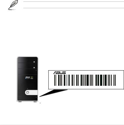
1.2Serial number label
Before requesting support from the ASUS Technical Support team, you must take note of the product’s serial number containing 12 characters such as xxxxxxxxxxxx. See the figure below.
With the correct serial number of the product, ASUS Technical Support team members can then offer a quicker and satisfying solution to your problems.
TW100-E5
xxxxxxxxxxxx
1-2 |
Chapter 1: Product introduction |
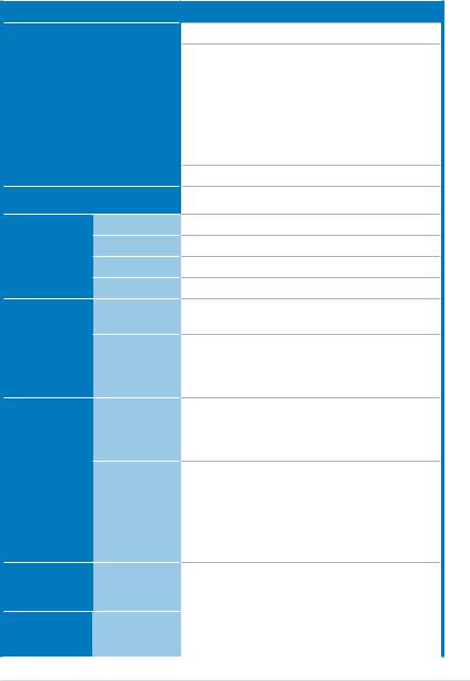
1.3System specifications
The ASUS TW100-E5 is a workstation featuring the ASUS P5N-VM WS motherboard. The workstation supports Intel® LGA775 Core™ 2 Extreme / Core™ 2 Quad / Core™ 2 Duo processors with EM64T technology, plus other latest technologies through the chipsets onboard.
Model Name
Processor / System Bus supported
Core Logic
Total Slots
Memory
Capacity
Memory Type
Memory Size
Total PCI/PCI-
X/PCI-E Slots
Expansion
Slots
Slot Type
SATA
Controller
Storage
SAS Controller
I = internal HDD Bays A or S will be
hot-swappable
TW100-E5
1 x Socket LGA775
Quad-Core Intel® Core™ 2 QX9000/Q9000 series (45nm)
Dual-Core Intel® Core™ 2 Duo E8000/E7000 series (45nm)
Quad-Core Intel® Core™ 2 Q6000 series Dual-Core Intel® Core™ 2 Duo E6000 series
Dual-Core Intel® Pentium E2220
Dual/Single-Core Intel Celeron
FSB 1333 / 1066 / 800 MHz with EM64T
NVIDIA® Quadro FX470
4 (Dual-Channel)
Maximum up to 8GB
DDR2 800 / 667 Non-ECC, Unbuffered
512MB, 1GB, and 2GB
4
1 x PCIe 2.0 x16 slot (x16 link)
1 x PCIe x4 slot (x1 link) for SAS
1 x PCIe x1 slot (x1 link)
1 x PCI 32-bit / 33MHz slot
NVIDIA Quadro FX470 6 SATA2 300MB/s ports
SATA RAID 0, 1, 5 and JBOD (Windows, Linux kernal 2.6.24 and above)
Option 1:
SASsaby 1064E PCI-E 4-port SAS Add-on Card (Support LSI® Integrated RAID 0, 1, and 1E)
Option 2:
SASsaby M PCI-E 4-port SAS Add-on Card
(Support Hardware RAID 0, 1, 10 and 5)
3 x Internal SATA HDD Cages
Networking |
LAN |
|
2 x Realtek® RTL8111C Gigabit LAN controllers |
|
|
- Supports teaming function |
|||
|
|
|
||
|
|
|
|
|
|
|
(continued on the next page) |
||
ASUS TW100-E5 |
1-3 |

Graphic VGA
Auxiliary Storage FDD / CD /
DVD
Onboard I/O
OS Support
Anti-virus Software
Dimension (HH x WW x DD)
Net Weight Kg (CPU, DRAM & HDD excluded)
Power Supply
Environment
-Integrated Quadro FX470
-Quadro Nview: Quad Display with single discrete Quadro card
-OpenGL 2.1 & DX10 support
-Dual DVI-I support
1 x 3.5” 7-in-1 Card Reader (optional) 1 x 5.25” DVD-RW
1 x PS/2 Keyboard/Mouse combo port
2 x RJ-45 ports
1 x S/PDIF Out (Coaxial + Optical)
12 x USB ports (Rear: 6, Front: 2, onboard pin header: 2)
1 x 8 channel audio I/O
2 x DVI-I ports:
-Upper: Single Link with max. resolution up to
1920x1200
-Lower: Dual Link with max resolution up to
2560x1600
Genuine Windows® XP Professional 32 / 64-bit Genuine Windows® Vista Business 32 / 64-bit
Norton® Internet Security 2008 (Trial Version)
355mm x 170mm x 395mm
10.8 Kg
390W Single Power Supply
Operation temperature: 10°C–35°C Non operation temperature: -40°C–70°C Non operation humidity: 20%–90% (Noncondensing)
*Specifications are subject to change without notice.
1-4 |
Chapter 1: Product introduction |

1.4Front panel features
The barebone workstation displays a simple yet stylish front panel with easily accessible features. The power and reset buttons, LED indicator, optical drive, card reader, and two USB ports are located on the front panel. For future installation of 5.25-inch devices, one drive bay is available.
Optical Drive
Empty 5.25-inch bay
7-in-1 Card Reader
Reset button
Power button / Power LED (blue) /
HDD access LED (yellow)
USB 2.0 / Microphone /
Headphone ports
Refer to section 1.7.1 Front panel LED for the LED descriptions.
ASUS TW100-E5 |
1-5 |

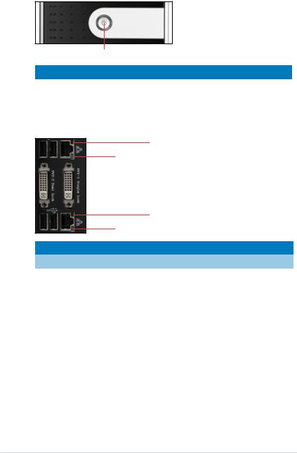
1.5Rear panel features
The rear panel includes a slot for the motherboard rear I/O ports, expansion slots, a power supply module, and a vent for the system fan.
The PS/2 keyboard / mouse combo port, USB ports, DVI-I ports, Audio ports, S/PDIF Out ports, and Gigabit LAN ports do not appear on the rear panel if motherboard is not present.
Power cord connector
USB 2.0 ports 
 Optical S/PDIF Out port
USB 2.0 ports 


DVI-I port (Dual Link)
USB 2.0 ports 
 8-channel audio ports
Power supply module Power supply switch
PS/2 keyboard / mouse combo port
Coaxial S/PDIF Out port LAN2 (RJ-45) port
DVI-I port (Single Link) System fan
LAN1 (RJ-45) port
Expansion slots
1-6 |
Chapter 1: Product introduction |

1.6Internal features
The barebone workstation includes the basic components as shown.
5
1
6
7
4
2
9
3
8
1.Power supply unit
2.92mm system fan
3.ASUS P5N-VM WS motherboard
4.CPU Heatsink
5.Optical drive
6.5.25-inch drive bay
7.7-in-1 Card Reader (hidden)
8.Front I/O board (hidden)
9.Internal HDD bays
ASUS TW100-E5 |
1-7 |
1.7LED information
1.7.1Front panel LED
Power LED / HDD Access LED
LED |
Color |
Display status |
Description |
Power LED |
Blue |
ON |
System power ON |
HDD Access |
Yellow |
OFF |
No activity |
LED |
|
Blinking |
Read/write data into the HDD |
1.7.2LAN (RJ-45) LEDs
ACT/LINK LED
SPEED LED
ACT/LINK LED
SPEED LED
ACT/LINK LED |
|
SPEED LED |
|
Status |
Description |
Status |
Description |
OFF |
No link |
OFF |
10 Mbps connection |
YELLOW |
Linked |
ORANGE |
100 Mbps connection |
BLINKING |
Data activity |
GREEN |
1 Gbps connection |
1-8 |
Chapter 1: Product introduction |

Chapter 2
This chapter lists the hardware setup procedures that you have to perform when installing or removing system components.
ASUS TW100-E5
Hardware setup
2-

2.1Chassis covers
2.1.1Removing the left side cover
You have to remove the left side cover to install or replace internal components of the server system.
•Ensure that you unplug the power cord before removing the side cover.
•Take extra care when removing the side cover. Keep your fingers from components inside the chassis that can cause injury, such as the CPU fan, rear fan, and other sharp-edged parts.
To remove the left side cover
1.Remove the two screws that secure the left side cover to the chassis.
1
1
2.Slide the left side cover for about half an inch toward the rear until it is disengaged from the chassis.
3.Carefully lift the cover and set it aside.
2
2-2 |
Chapter 2: Hardware setup |
2.1.2Removing the right side cover
Most internal components can be installed or replaced after removing the left side cover. However, for components such as Serial ATA hard disk drives, you may have to remove the right side cover for easier component installation or replacement.
To remove the right side cover
1.Remove the two screws that secure the left side cover to the chassis.
2.Slide the right side cover for about half an inch toward the rear until it is disengaged from the chassis.
3.Carefully lift the cover and set it aside.
1
1
2
ASUS TW100-E5 |
2-3 |

2.2Motherboard overview
The barebone server comes with the P5N-VM WS motherboard already installed. The motherboard is secured to the chassis by eight (8) screws as indicated by the circles in the illustration below.
Refer to Chapter 3: Motherboard information for detailed information on the motherboard.
Place this side towards the rear of the chassis
Ensure to unplug the power cord before installing or removing any motherboard component or connection. Failure to do so can cause you physical injury and damage motherboard components.
2-4 |
Chapter 2: Hardware setup |

2.3Central Processing Unit (CPU)
The motherboard comes with a surface mount LGA775 socket designed for the Intel® Core™ 2 Extreme / Core™ 2 Quad / Core™ 2 Duo / Pentium® dual-core / Celeron® dual-core / Celeron® processors.
2.3.1Installing the CPU
To install a CPU:
1.Locate the CPU socket on the motherboard.
Before installing the CPU, make sure that the socket box is facing towards you and the load lever is on your left.
2.Press the load lever with your thumb (A), then move it to the left
(B)until it is released from the retention tab.
To prevent damage to the socket pins, do not remove the PnP cap unless you are installing a CPU.
Retention tab
A
B
Load lever
3.Lift the load lever in the direction of the arrow to a 135º angle.
4.Lift the load plate with your thumb and forefinger to a 100º angle (4A), then push the PnP cap from the load plate window to remove (4B).
PnP cap
Load plate
4B
4A
3
ASUS TW100-E5 |
2-5 |

5. |
Position the CPU over the socket, |
CPU notch |
|
making sure that the gold triangle |
|
|
|
|
|
is on the bottom left corner of the |
|
|
socket then fit the socket alignment |
|
|
key into the CPU notch. |
|
The CPU fits in only one correct orientation. DO NOT force the CPU into the socket to prevent bending the connectors on the socket and damaging the CPU!
Alignment key
Gold triangle mark
6.Apply several drops of thermal paste to the exposed area of the CPU that
the heatsink will be in contact with, ensuring that it is spread in an even thin layer.
Some heatsinks come with preapplied thermal paste. If so, skip this step.
The Thermal Interface Material is toxic and inedible. If it gets into your eyes or touches your skin, ensure to wash it off immediately, and seek professional medical help.
To prevent contaminating the paste, DO NOT spread the paste with your finger directly.
2-6 |
Chapter 2: Hardware setup |

7.Close the load plate (A), then push the load lever (B) until it snaps into the retention tab.
A
B
ASUS TW100-E5 |
2-7 |

2.3.2Installing the CPU heatsink
The Intel® Core™ 2 Extreme / Core™ 2 Quad / Core™ 2 Duo / Pentium® dualcore / Celeron® dual-core / Celeron® processors require an Intel certified or ASUS qualified heatsink and fan assembly to ensure optimum thermal condition and performance.
When you buy a boxed Intel CPU, the package includes the cooler, fan, thermal grease, installation manual, and other items that are necessary for CPU installation.
• Ensure that you have applied the thermal grease to the top of the CPU before installing the heatsink and fan.
•Refer to the installation manual that came with the CPU package for details on heatsink/fan assmbly and installation.
To install the CPU cooler and fan
1.Place the cooler on top of the installed CPU, making sure that the four screws match the holes on the support plate.
The support plate only comes with the optional CPU heatsink. If you buy a boxed Intel CPU with a bundled CPU fan, you can install the CPU fan without the support plate.
2.Use a screwdriver to tighten the four (4) cooler screws in a diagonal sequence.
AB
BA
2-8 |
Chapter 2: Hardware setup |

3. Connect the CPU fan cable to the connector on the motherboard labeled CPU_FAN.
Do not forget to connect the CPU_FAN connector! Hardware monitoring errors can occur if you fail to plug this connector.
ASUS TW100-E5 |
2-9 |

2.4System memory
2.4.1Overview
The motherboard comes with four Double Data Rate II (DDR2) Dual Inline Memory Modules (DIMM) sockets to support 240-pin DDR2 modules.
The figure illustrates the location of the DDR2 DIMM sockets:
|
|
|
|
|
|
|
|
|
|
|
|
|
|
|
|
|
|
|
|
|
|
|
|
|
|
|
|
|
|
|
|
|
|
|
|
|
|
|
|
|
|
|
|
|
|
|
|
|
|
|
|
|
|
|
|
|
|
|
|
|
|
|
|
|
|
|
|
|
|
|
|
|
|
|
|
|
|
|
|
|
|
|
|
|
|
|
|
|
|
|
|
|
|
|
|
|
|
|
|
|
|
|
|
|
|
|
|
|
|
|
|
|
|
|
|
|
|
|
|
|
|
|
|
|
|
|
|
|
|
|
|
|
|
|
|
|
|
|
|
|
|
|
|
|
|
|
|
|
|
|
|
|
|
|
|
|
|
|
|
|
|
|
|
|
|
|
|
|
|
|
|
|
|
|
|
|
|
|
|
|
|
|
|
|
|
|
|
|
|
|
|
|
|
|
|
|
|
|
|
|
|
|
|
|
|
|
|
|
|
|
|
|
|
|
|
|
|
|
|
|
|
|
|
|
|
|
|
|
|
|
|
|
|
|
|
|
|
|
|
|
|
|
|
|
|
|
|
|
|
|
|
|
|
|
|
|
|
|
|
|
|
|
|
|
|
|
|
|
|
|
|
|
|
|
|
|
|
|
|
|
|
|
|
|
|
|
|
|
|
|
|
|
|
|
|
|
|
|
|
|
|
|
|
|
|
|
|
|
|
|
|
|
|
|
|
|
|
|
|
|
|
|
|
|
|
|
|
|
|
|
|
|
|
|
|
|
|
|
|
|
|
|
|
|
|
|
|
|
|
|
|
|
|
|
|
|
|
|
|
|
|
|
|
|
|
|
|
|
|
|
|
|
|
|
|
|
|
|
|
|
|
|
|
|
|
|
|
|
|
|
|
|
|
|
|
|
|
|
|
|
|
|
|
|
|
|
|
|
|
|
|
|
|
|
|
|
|
|
|
|
|
|
|
|
|
|
|
|
|
|
|
|
|
|
|
|
|
|
|
|
|
|
|
|
|
|
|
|
|
|
|
|
|
|
|
|
|
|
|
|
|
|
|
|
|
|
|
|
|
|
|
|
|
|
|
|
|
|
|
|
|
|
|
|
|
|
|
|
|
|
|
|
|
|
|
|
|
|
|
|
|
|
|
|
|
|
|
|
|
|
|
|
|
|
|
|
|
|
|
|
|
|
|
|
|
|
|
|
|
|
|
|
|
|
|
|
|
|
|
|
|
|
|
|
|
|
|
|
|
|
|
|
|
|
|
|
|
|
|
|
|
|
|
|
|
|
|
|
|
|
|
|
|
|
|
|
|
|
|
|
|
|
|
|
|
|
|
|
|
|
|
|
|
|
|
|
|
|
|
|
|
|
|
|
|
|
|
|
|
|
|
|
|
|
|
|
|
|
|
|
|
|
|
|
|
|
|
|
|
|
|
|
|
|
|
|
|
|
|
|
|
|
|
|
|
|
|
|
|
|
|
|
|
|
|
|
|
|
|
|
|
|
|
|
|
|
|
|
|
|
|
|
|
|
|
|
|
|
|
|
|
|
|
|
|
|
|
|
|
|
|
|
|
|
|
|
|
|
|
|
|
|
|
|
|
|
|
|
|
|
|
|
|
|
|
|
|
|
|
|
|
|
|
|
|
|
|
|
|
|
|
|
|
|
|
|
|
|
|
|
|
|
|
|
|
|
|
|
|
|
|
|
|
|
|
|
|
|
|
|
|
|
|
|
|
|
|
|
|
|
|
|
|
|
|
|
|
|
|
|
|
|
|
|
|
|
|
|
|
|
|
|
|
|
|
|
|
|
|
|
|
|
|
|
|
|
|
|
|
|
|
|
|
|
|
|
|
|
|
|
|
|
|
|
|
|
|
|
|
|
|
|
|
|
|
|
|
|
|
|
|
|
|
|
|
|
|
|
|
|
|
|
|
|
|
|
|
|
|
|
|
|
|
|
|
|
|
|
|
|
|
|
|
|
|
|
|
|
|
|
|
|
|
|
|
|
|
|
|
|
|
|
|
|
|
|
|
|
|
|
|
|
|
|
|
|
|
|
|
|
|
|
|
|
|
|
|
|
|
|
|
|
|
|
|
|
|
|
|
|
|
|
|
|
|
|
|
|
|
|
|
|
|
|
|
|
|
|
|
|
|
|
|
|
|
|
|
|
|
|
|
|
|
|
|
|
|
|
|
|
|
|
|
|
|
|
|
|
|
|
|
|
|
|
|
|
|
|
|
|
|
|
|
|
|
|
|
|
|
|
|
|
|
|
|
|
|
|
|
|
|
|
|
|
|
|
|
|
|
|
|
|
|
|
|
|
|
|
|
|
|
|
|
|
|
|
|
|
|
|
|
|
|
|
|
|
|
|
|
|
|
|
|
|
|
|
|
|
|
|
|
|
|
|
|
|
|
|
|
|
|
|
|
|
|
|
|
|
|
|
|
|
|
|
|
|
|
|
|
|
|
|
|
|
|
|
|
|
|
|
|
|
|
|
|
|
|
|
|
|
|
|
|
|
|
|
|
|
|
|
|
|
|
|
|
|
|
|
|
|
|
|
|
|
|
|
|
|
|
|
|
|
|
|
|
|
|
|
|
|
|
|
|
|
|
|
|
|
|
|
|
|
|
|
|
|
|
|
|
|
|
|
|
|
|
|
|
|
|
|
|
|
|
|
|
|
|
|
|
|
|
|
|
|
|
|
|
|
|
|
|
|
|
|
|
|
|
|
|
|
|
|
|
|
|
|
|
|
|
|
|
|
|
|
|
|
|
|
|
|
|
|
|
|
|
|
|
|
|
|
|
|
|
|
|
|
|
|
|
|
|
|
|
|
|
|
|
|
|
|
|
|
|
|
|
|
|
|
|
|
|
|
|
|
|
|
|
|
|
|
|
|
|
|
|
|
|
|
|
|
|
|
|
|
|
|
|
|
|
|
|
|
|
|
|
|
|
|
|
|
|
|
|
|
|
|
|
|
|
|
|
|
|
|
|
|
|
|
|
|
|
|
|
|
|
|
|
|
|
|
|
|
|
|
|
|
|
|
|
|
|
|
|
|
|
|
|
|
|
|
|
|
|
|
|
|
|
|
|
|
|
|
|
|
|
|
|
|
|
|
|
|
|
|
|
|
|
|
|
|
|
|
|
|
|
|
|
|
|
|
|
|
|
|
|
|
Channel |
|
|
|
|
Sockets |
|
||||||||||||||||||||||||||||||||||||||||||
|
|
|
Channel A |
|
|
|
|
DIMM_A1 and DIMM_A2 |
|
||||||||||||||||||||||||||||||||||||||||||
|
|
|
Channel B |
|
|
|
|
DIMM_B1 and DIMM_B2 |
|
||||||||||||||||||||||||||||||||||||||||||
Recommend memory configuration
Mode |
Sockets |
|
|
|
|
DIMM_B1 |
DIMM_B2 |
DIMM_A1 |
DIMM_A2 |
||
|
|||||
Single-channel |
- |
- |
populated |
- |
|
populated |
- |
- |
- |
||
|
|||||
Dual-channel (1) |
populated |
- |
populated |
- |
|
Dual-channel (2) |
- |
populated |
- |
populated |
|
Full |
populated |
populated |
populated |
populated |
2-10 |
Chapter 2: Hardware setup |

2.4.2Memory configurations
You may install 512 MB, 1 GB, and 2 GB non ECC, unbuffered DDR2 DIMMs into the DIMM sockets.
• You may install varying memory sizes in Channel A and Channel B. The system maps the total size of the lower-sized channel for the dual-channel configuration. Any excess memory from the higher-sized channel is then mapped for single-channel operation.
•Always install DIMMs with the same CAS latency. For optimum compatibility, it is recommended that you obtain memory modules from the same vendor.
•When installing total memory of 4GB capacity or more, Windows 32bit operation system may only recognize less than 3GB. Hence, a total installed memory of less than 3GB is recommended.
•This motherboard does not support memory modules made up of 128 Mb chips.
• Due to chipset limitation, this motherboard can only support up to
8 GB on the operating systems listed below. You may install a maximum of 2 GB DIMMs on each slot.
64-bit
Windows® XP Professional x64 Edition
Windows® Vista x64 Edition
•The memory modules may require a better cooling system to work stably under full loading (4 DIMMs) setting.
ASUS TW100-E5 |
2-11 |
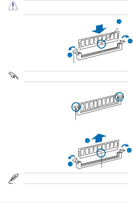
2.4.3Installing a DIMM
Make sure to unplug the power supply before adding or removing DIMMs or other system components. Failure to do so may cause severe damage to both the motherboard and the components.
1. |
Unlock a DDR2 DIMM socket |
2 |
DDR2 DIMM notch |
||
|
by pressing the retaining clips |
|
|
outward. |
|
2. |
Align a DIMM on the socket |
1 |
such that the notch on the DIMM matches the break on the socket.
1
Unlocked retaining clip
A DDR2 DIMM is keyed with a notch so that it fits in only one direction. DO NOT force a DIMM into a socket to avoid damaging the DIMM.
3. Firmly insert the DIMM into the |
3 |
|
socket until the retaining clips snap |
|
|
back in place and the DIMM is |
|
|
properly seated. |
|
|
|
Locked Retaining Clip |
|
2.4.4 |
Removing a DIMM |
|
Follow these steps to remove a DIMM. |
2 |
|
1
1. Simultaneously press the retaining clips outward to unlock
the DIMM. 1
DDR2 DIMM notch
Support the DIMM lightly with your fingers when pressing the retaining clips. The DIMM might get damaged when it flips out with extra force.
2.Remove the DIMM from the socket.
2-12 |
Chapter 2: Hardware setup |
 Loading...