


TS500-E4 Server
Pedestal/5U Rackmount Server
User's Manual

E2785
First Edition V1
September 2006
Copyright 2006© ASUSTeK COMPUTER INC. All Rights Reserved.
No part of this manual, including the products and software described in it, may be reproduced, transmitted, transcribed, stored in a retrieval system, or translated into any language in any form or by any means, except documentation kept by the purchaser for backup purposes, without the express written permission of ASUSTeK COMPUTER INC. ("ASUS").
ASUS provides this manual "as is" without warranty of any kind, either express or implied, including but not limited to the implied warranties or conditions of merchantability or fitness for a particular purpose. In no event shall ASUS, its directors, officers, employees, or agents be liable for any indirect, special, incidental, or consequential damages (including damages for loss of profits, loss of business, loss of use or data, interruption of business and the like), even if ASUS has been advised of the possibility of such damages arising from any defect or error in this manual or product.
Specifications and information contained in this manual ae furnished for informational use only, and are subject to change at any time without notice, and should not be construed as a commitment by ASUS. ASUS assumes no responsibility or liability for any errors or inaccuracies that may appear in this manual, including the products and software described in it.
Product warranty or service will not be extended if: (1) the product is repaired, modified or altered, unless such repair, modification of alteration is authorized in writing by ASUS; or (2) the serial number of the product is defaced or missing.
Products and corporate names appearing in this manual may or may not be registered trademarks or copyrights of their respective companies, and are used only for identification or explanation and to the owners benefit, without intent to infringe.

Contents
Contents.......................................................................................... |
iii |
|
Notices.......................................................................................... |
viii |
|
Safety information............................................................................ |
ix |
|
About this guide................................................................................ |
x |
|
1.Chapter 1: Product Introduction |
|
|
1.1 |
System package contents.......................................................... |
1-2 |
1.2 |
System specifications............................................................... |
1-3 |
1.3 |
Front panel features................................................................. |
1-5 |
1.4 |
Rear panel features................................................................... |
1-6 |
1.5 |
Internal features....................................................................... |
1-7 |
1.6 |
LED information...................................................................... |
1-9 |
|
1.6.1 Front panel LEDs............................................................... |
1-9 |
|
1.6.2 Rear panel LEDs.............................................................. |
1-10 |
2.Chapter 2: Hardware setup |
|
|
2.1 |
Chassis cover........................................................................... |
2-2 |
|
2.1.1 Removing the side cover.................................................... |
2-2 |
|
2.1.2 Reinstalling the side cover.................................................. |
2-3 |
2.2 |
Motherboard information.......................................................... |
2-4 |
2.3 |
Central Processing Unit (CPU)................................................... |
2-5 |
|
2.3.1 Installing the CPU.............................................................. |
2-5 |
|
2.3.2 Installing the CPU heatsink and fan..................................... |
2-8 |
2.4 |
System memory..................................................................... |
2-10 |
|
2.4.1 Overview........................................................................ |
2-10 |
|
2.4.2 Memory configurations..................................................... |
2-10 |
|
2.4.3 Installing a DIMM............................................................ |
2-12 |
|
2.4.4 Removing a DIMM........................................................... |
2-12 |
2.5 |
Front panel assembly.............................................................. |
2-13 |
|
2.5.1 Removing the front panel assembly.................................... |
2-13 |
|
2.5.2 Reinstalling the front panel assembly................................. |
2-15 |
2.6 |
5.25-inch drives.................................................................... |
2-16 |
2.7 |
Hard disk drives.................................................................... |
2-19 |
iii

Contents
|
2.7.1 Installing a hot-swap SATA/SAS HDD............................... |
2-19 |
|
2.7.2 Installing an HDD dummy cover........................................ |
2-21 |
2.8 |
Expansion cards..................................................................... |
2-22 |
|
2.8.1 Installing an expansion card.............................................. |
2-22 |
|
2.8.2 Removing an expansion card............................................. |
2-23 |
2.9 |
Cable connections................................................................... |
2-24 |
|
2.9.1 Motherboard layouts......................................................... |
2-24 |
|
2.9.2 SATA backplane connections ........................................... |
2-25 |
|
2.9.3 SAS backplane connections............................................... |
2-28 |
2.10 Removable components......................................................... |
2-31 |
|
|
2.10.1 Chassis fan.................................................................... |
2-31 |
|
2.10.2 HDD blower................................................................... |
2-33 |
|
2.10.3 SATA/SAS backplane..................................................... |
2-36 |
|
2.10.4 MemCool FB-DIMM fan kit......................................................... |
2-38 |
|
2.10.5 Floppy disk drive.......................................................... |
2-41 |
|
2.10.6 Front I/O board.............................................................. |
2-43 |
|
2.10.7 Chassis footpads and roller wheels................................... |
2-45 |
|
2.10.8 Power supply unit.......................................................... |
2-47 |
3.Chapter 3: Installation options |
|
|
3.1 |
Preparing the system for rack mounting.............................................. |
3-2 |
|
3.1.1 Removing the footpads or roller wheels................................ |
3-2 |
|
3.1.2 Removing the top cover...................................................... |
3-2 |
|
3.1.3 Attaching the rack rails...................................................... |
3-2 |
3.2 |
Installing ASUS certified CPU heatsink and fan assembly........... |
3-3 |
4.Chapter 4: Motherboard information |
|
|
4.1 |
Motherboard layouts................................................................. |
4-2 |
4.2 |
Jumpers................................................................................... |
4-4 |
4.3 |
Connectors............................................................................... |
4-9 |
|
4.3.1 Rear panel connectors......................................................... |
4-9 |
|
4.3.2 Internal connectors........................................................... |
4-10 |
5.Chapter 5: BIOS information |
|
|
5.1 |
Managing and updating your BIOS............................................ |
5-2 |
|
5.1.1 Creating a bootable floppy disk........................................... |
5-2 |
iv
Contents
5.1.2 Updating the BIOS using the Phoenix Phlash16 Utility |
.........5-3 |
5.1.3 ASUS CrashFree BIOS 2 utility........................................... |
5-4 |
5.1.4 ASUS Update utility........................................................... |
5-6 |
5.2 BIOS setup program................................................................. |
5-9 |
5.2.1 BIOS menu screen............................................................ |
5-10 |
5.2.2 Menu bar........................................................................ |
5-10 |
5.2.3 Legend bar...................................................................... |
5-11 |
5.2.4 Menu items..................................................................... |
5-11 |
5.2.5 Sub-menu items............................................................... |
5-11 |
5.2.6 Configuration fields.......................................................... |
5-11 |
5.2.7 Pop-up window............................................................... |
5-12 |
5.2.8 General help.................................................................... |
5-12 |
5.3 Main menu............................................................................ |
5-13 |
5.3.1 System Date [Day xx/xx/xxxx].......................................... |
5-13 |
5.3.2 System Time [xx:xx:xx]................................................... |
5-13 |
5.3.3 Floppy A [1.44M, 3.5 in.]............................................... |
5-13 |
5.3.4 IDE Configuration............................................................ |
5-14 |
5.3.5 IDE Channel 0 Master/Slave; SATA Port 1/2/3/4................ |
5-16 |
5.3.6 System Information.......................................................... |
5-17 |
5.4 Advanced menu..................................................................... |
5-19 |
5.4.1 Advanced Processor Options.............................................. |
5-19 |
5.4.2 Chipset Configuration....................................................... |
5-21 |
5.4.3 PCI Configuration............................................................ |
5-23 |
5.4.4 ICH USB Control Sub-Menu............................................... |
5-25 |
5.4.5 Peripheral Devices Configuration....................................... |
5-26 |
5.4.6 ACPI Configuration.......................................................... |
5-28 |
5.4.7 Power On Configuration................................................... |
5-29 |
5.4.8 Hardware Monitor............................................................ |
5-30 |
5.5 Server menu.......................................................................... |
5-33 |
5.5.1 Console Redirection.......................................................... |
5-33 |
5.5.2 DMI Event Logging.......................................................... |
5-35 |
5.6 Security menu........................................................................ |
5-36 |
5.7 Boot menu............................................................................. |
5-38 |
5.7.1 Boot Device Priority......................................................... |
5-38 |
5.7.2 Boot Features................................................................... |
5-39 |
5.8 Exit menu............................................................................. |
5-40 |
|
|

Contents
6.Chapter 6: RAID configuration
6.1 Setting up RAID...................................................................... |
6-2 |
6.1.1 RAID definitions................................................................ |
6-2 |
6.1.2 Installing hard disk drives.................................................. |
6-3 |
6.1.3 Setting the RAID item in BIOS............................................ |
6-3 |
6.1.4 RAID configuration utilities................................................ |
6-3 |
6.2 LSI Logic Embedded SATA RAID Setup Utility (Only for PA4
Model).................................................................................... |
6-4 |
6.2.1 Creating a RAID 0 or RAID 1 set........................................ |
6-5 |
6.2.2 Creating a RAID 10 set.................................................... |
6-11 |
6.2.3 Adding or viewing a RAID configuration........................... |
6-15 |
6.2.4 Initializing the logical drives............................................ |
6-18 |
6.2.5 Rebuilding failed drives................................................... |
6-23 |
6.2.6 Checking the drives for data consistency............................ |
6-25 |
6.2.7 Deleting a RAID configuration.......................................... |
6-28 |
6.2.8 Selecting the boot drive from a RAID set........................... |
6-29 |
6.2.9 Enabling the WriteCache................................................... |
6-30 |
6.3 Intel® Matrix Storage Manage Option ROM Utility (Only for PA4
|
model).................................................................................. |
6-31 |
|
6.3.1 Creating a RAID 0 set (Stripe).......................................... |
6-32 |
|
6.3.2 Creating a RAID 1 set (Mirror)......................................... |
6-34 |
|
6.3.3 Creating a RAID 10 set (Stripe + Mirror)........................... |
6-35 |
|
6.3.4 Creating a RAID 5 set (Parity).......................................... |
6-36 |
|
6.3.5 Deleting a RAID set......................................................... |
6-37 |
|
6.3.6 Resetting disks to Non-RAID............................................ |
6-38 |
|
6.3.7 Exiting the Intel® Matrix Storage Manager......................... |
6-38 |
6.4 |
Global Array Manager............................................................ |
6-39 |
7.Chapter 7: Driver installation |
|
|
7.1 |
RAID driver installation........................................................... |
7-2 |
|
7.1.1 Creating a RAID driver disk............................................... |
7-2 |
|
7.1.2 Installing the RAID controller driver..................................... |
7-3 |
7.2 |
LAN driver installation........................................................... |
7-12 |
|
7.2.1 Windows 2000/Server 2003............................................ |
7-12 |
|
7.2.2 Red Hat/SuSE Linux........................................................ |
7-16 |
7.3 |
VGA driver installation.......................................................... |
7-17 |
vi

7.3.1 Windows 2000/Server 2003. |
...........................................7-17 |
Appendix: Reference information |
|
A.1 670 W single power supply..................................................... |
A-2 |
A.1.1 General description........................................................... |
A-2 |
A.1.2 Specifications................................................................... |
A-3 |
A.2 Simple fixes............................................................................ |
A-4 |
vii
Notices
Federal Communications Commission Statement
This device complies with Part 15 of the FCC Rules. Operation is subject to the following two conditions:
This device may not cause harmful interference, and
This device must accept any interference received including interference that may cause undesired operation.
This equipment has been tested and found to comply with the limits for a Class A digital device, pursuant to Part 15 of the FCC Rules. These limits are designed to provide reasonable protection against harmful interference in a residential installation. This equipment generates, uses and can radiate radio frequency energy and, if not installed and used in accordance with manufacturer's instructions, may cause harmful interference to radio communications. However, there is no guarantee that interference will not occur in a particular installation. If this equipment does cause harmful interference to radio or television reception, which can be determined by turning the equipment off and on, the user is encouraged to try to correct the interference by one or more of the following measures:
Reorient or relocate the receiving antenna.
Increase the separation between the equipment and receiver.
Connect the equipment to an outlet on a circuit different from that to which the receiver is connected.
Consult the dealer or an experienced radio/TV technician for help.
WARNING! The use of shielded cables for connection of the monitor to the graphics card is required to assure compliance with FCC regulations. Changes or modifications to this unit not expressly approved by the party responsible for compliance could void the user's authority to operate this equipment.
Canadian Department of Communications Statement
This digital apparatus does not exceed the Class A limits for radio noise emissions from digital apparatus set out in the Radio Interference Regulations of the Canadian Department of Communications.
This Class A digital apparatus complies with Canadian ICES-003.
viii

Safety information
Electrical Safety
Before installing or removing signal cables, ensure that the power cables for the system unit and all attached devices are unplugged.
To prevent electrical shock hazard, disconnect the power cable from the electrical outlet before relocating the system.
When adding or removing any additional devices to or from the system, ensure that the power cables for the devices are unplugged before the signal cables are connected. If possible, disconnect all power cables from the existing system before you add a device.
If the power supply is broken, do not try to fix it by yourself. Contact a qualified service technician or your dealer.
Operation Safety
Any mechanical operation on this server must be conducted by certified or experienced engineers.
Before operating the server, carefully read all the manuals included with the server package.
Before using the server, make sure all cables are correctly connected and the power cables are not damaged. If any damage is detected, contact your dealer as soon as possible.
To avoid short circuits, keep paper clips, screws, and staples away from connectors, slots, sockets and circuitry.
Avoid dust, humidity, and temperature extremes. Place the server on a stable surface.
This product is equipped with a three-wire power cable and plug for the user's safety. Use the power cable with a properly grounded electrical outlet to avoid electrical shock.
Lithium-Ion Battery Warning
CAUTION! Danger of explosion if battery is incorrectly replaced. Replace only with the same or equivalent type recommended by the manufacturer. Dispose of used batteries according to the manufacturer's instructions.
 CD-ROM Drive Safety Warning
CLASS 1 LASER PRODUCT
Heavy System
CAUTION! This server system is heavy. Ask for assistance when moving or carrying the system.
ix

About this guide
Audience
This user guide is intended for system integrators and experienced users with at least basic knowledge of configuring a server.
Contents
This guide contains the following parts:
1.Chapter 1: Product Introduction
This chapter describes the general features of the server, including sections on front panel and rear panel specifications.
2.Chapter 2: Hardware setup
This chapter lists the hardware setup procedures that you have to perform when installing or removing system components.
3.Chapter 3: Installation options
This chapter describes how to install optional components into the barebone server.
4.Chapter 4: Motherboard information
This chapter gives information about the motherboard that comes with the server. This chapter includes the motherboard layout, jumper settings, and connector locations.
5.Chapter 5: BIOS information
This chapter tells how to change system settings through the BIOS Setup menus and describes the BIOS parameters.
6.Chapter 6: RAID configuration
This chapter provides information on how toconfigure your hard disk drives as RAID sets.
7.Chapter 7: Driver installation
This chapter provides information on how to create a RAID set and how to install the drivers for system components. This chapter also describes the software applications that the barebone server supports.
8.Appendix: Reference information
This section provides information about the power supply unit and a troubleshooting guide for solving common problems when using the barebone server.
About this guide
Audience
This user guide is intended for system integrators and experienced users with at least basic knowledge of configuring a server.
Conventions
To make sure that you perform certain tasks properly, take note of the following symbols used throughout this manual.
WARNING: Information to prevent injury to yourself when trying to complete a task.
CAUTION: Information to prevent damage to the components when trying to complete a task.
IMPORTANT: Instructions that you MUST follow to complete a task.
NOTE: Tips and information to aid in completing a task.
References
Refer to the following sources for additional information, and for product and software updates.
1.ASUS Server Web-based Management (ASWM) user guide
This manual tells how to set up and use the proprietary ASUS server management utility.
2.ASUS websites
The ASUS websites worldwide provide updated information for all ASUS hardware and software products. Refer to the ASUS contact information.
xi

xii

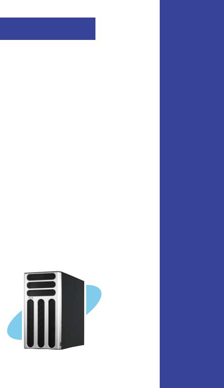
Chapter 1
This chapter describes the general features of the chassis kit. It includes sections on front panel and rear panel specifications.
Product introduction

1.1 System package contents
Check your system package for the following items.
|
Configuration |
|
|
Item Description |
PA4 |
|
PX4 |
1) ASUS T30 pedestal 5U rackmount chassis with: |
|
|
|
ASUS DSBV-D motherboard |
• |
|
• |
670 W single power supply |
• |
|
• |
SATA backplane board |
• |
|
|
SAS* backplane board |
|
|
• |
SAS control card |
|
|
• |
SATA Cable (4 pcs.) |
• |
|
|
SAS Cable (1 pcs.) |
|
|
• |
CD-ROM or DVD-ROM drive |
• |
|
• |
Floppy disk drive |
• |
|
• |
Chassis fan |
• |
|
• |
HDD blower |
• |
|
• |
MemCool FB-DIMM fan kit |
• |
|
• |
Hot-swap HDD trays (including HDD screws) |
• |
|
• |
Chassis roller wheels (4 sets) |
• |
|
• |
Front I/O board |
• |
|
• |
SMBus cable |
• |
|
• |
Dummy Covers (2 pcs.) |
• |
|
• |
Parallel port cable (1 pcs) |
• |
|
• |
2) AC power cable |
• |
|
• |
3) System screws and cables |
• |
|
• |
4) System keys ( 2 pcs.) |
• |
|
• |
5) Bundled CDs |
|
|
|
TS500-E4 support CD with ASWM** |
• |
|
• |
Computer Associates eTrust anti-virus CD |
• |
|
• |
SAS/RAID control card drivers CD with user guide |
|
|
• |
6) Documentation |
|
|
|
ASUS TS500-E4 user guide |
• |
|
• |
ASUS ASWM 2.0 user guide |
• |
|
• |
7) Optional items |
|
|
|
ASUS AK25 rackmount rail kit |
• |
|
• |
ASUS certified heatsink and fan assembly |
• |
|
• |
*Serial-Attached SCSI
**ASUS System Web-based Management
Contact your dealer immediately if any of the items is damaged or missing.
1- |
Chapter 1: Product introduction |

1.2 System specifications
The ASUS TS500-E4 is a pedestal/5U barebone server system featuring the ASUS DSBV-D motherboard. The server supports dual Intel LGA771 Xeon processors with EM64T technology, plus other latest technologies through the chipsets onboard.
Chassis |
Pedestal/Rackmount 5U |
Motherboard |
ASUS DSBV-D |
Chipset |
North Bridge: Intel® 5000V MCH |
|
South Bridge: Intel® 6321ESB ICH |
CPU |
Supports Dual LGA771 sockets Intel® Xeon processors |
|
Supports Dual-Core Xeon Dempsey1066/Woodcrest1333/ |
|
Clovertown1066 processor |
|
Supports 667/1066/1333MHz FSB(Front Sied Bus) |
Memory |
6 x DDRII Fully Buffer DIMM (FBDIMM) sockets support ECC |
|
DDRII-667/533 MHz memory modules |
|
Supports 512MB up to 24GB system memory |
LAN |
2 x Gigabit LAN (Intel® 82563EB PCI-E Gigabit LAN controller) |
VGA |
ATI ES1000 VGA controller |
|
Supports 32MB display memory |
Storage |
4 x Hot-Swap SATA2(PA4 & PX4 Model)/SAS(PX4 Model Only) |
|
HDDs bay |
|
3 x 5.25" Drive bay, 1 x 1.44MB FDD bay |
RAID |
Intel® 6321ESB ICH controller supports(PA4 Model Only): |
|
- Intel Matrix Storage (Windows) support RAID 0, RAID 1, RAID 0+1, |
|
RAID5(S/W) |
|
- LSI MegaRAID(Linux/Windows) support RAID 0, RAID 1, RAID 0+1 |
|
LSI SA3442X-R HBA supports(PX4 Model Only): |
|
- RAID 0, RAID 1 and RAID 1E |
Expansion slots |
1 x 32-bit/33MHz/5V PCI slot |
|
3 x 64-bit/133/100MHz 3V PCI-X slots |
|
1 x PCI-Express x16 slot (x8 link) |
|
1 x PCI-Express x8 slot ( x4 link) |
|
1 x SO-DIMM for ASUS ASMB3-SOL Management Board (Optional) |
Front panel |
4 x 3.5-inch hot-swappable SAS/SATA-II HDD bays |
|
1 x optical drive |
|
2 x USB 2.0 ports |
|
Power switch |
|
Reset switch |
|
LEDs: Power, HDD access, message |
|
Drive LEDs: Status, activity |
|
(continued on the next page) |
ASUS TS500-E4 |
1- |

Rear panel |
1 x PS/2 keyboard port |
|
1 x PS/2 mouse port |
|
1 x Serial port |
|
1 x VGA port |
|
2 x USB 2.0 ports |
|
2 x RJ-45 ports (with LEDs) |
|
1 x Power connector |
Management |
ASUS Server Web-based Management (ASWM) |
Hardware |
SM-Bus, ASMB3 supports IMIP 2.0 LAN management card |
support |
|
Hardware |
Voltage, temperature, and fan speed monitoring |
monitors |
Automatic System Restart (ASR) feature |
Power supply |
670W single power supply, 100V~240V, 50Hz~60Hz |
Dimensions |
431mm (H) x 220mm (W) x 510mm (D) |
Specifications are subject to change without notice.
1- |
Chapter 1: Product introduction |

1.3 Front panel features
The barebone server displays a simple and stylish front panel with easily accessible features.
The drive bays, power and reset buttons,
LED indicators, optical drive, floppy drive, and USB 2.0 ports are located on the front panel. For future installation of 5.25-inch devices, two drive bays are available.
Optical drive
Empty 5.25-inch bays
Power button
Reset button
Message LED
HDD access LED
Power LED
Floppy disk drive
USB 2.0 ports
HDD bays
Security lock
ASUS TS500-E4 |
1- |
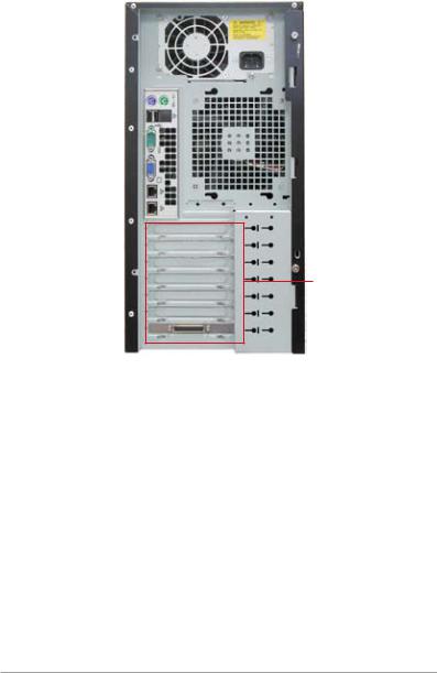
1.4 Rear panel features
The rear panel includes a slot for the motherboard rear I/O ports, expansion slots, a chassis lock and intrusion switch, a vent for the system fan, and power supply module.
|
|
|
|
|
|
|
|
|
Power supply module |
|
|
|
|
|
|
|
|
|
|
|
|
|
|
|
|
|
|
|
Power connector |
|
|
|
|
|
|
|
|
|
|
PS/2 keyboard port |
|
|
|
|
|
|
|
PS/2 mouse port |
|
|
|
|
|
|
|
|
|||
USB 2.0 ports |
|
|
|
|
|
|
|
|
|
|
|
|
|
|
|
|
|
||
Serial port |
|
|
|
|
|
|
|
12 cm system fan |
|
|
|
|
|
|
|
|
|||
VGA port |
|
|
|
|
|
|
|
|
|
|
|
|
|
|
|
|
|
||
Gigabit LAN ports |
|
|
|
|
|
|
|
|
|
|
|
|
|
|
|
|
|
||
|
|
|
|
|
|
|
|
||
|
|
|
|
|
|
|
|
|
|
Expansion slots
1- |
Chapter 1: Product introduction |

1.5 Internal features
The barebone server system includes the basic components as shown. The photo below shows the TS500-E4 with the disk blower installed.
PA4 (4 hot-swap SATA configuration)
|
|
1 |
6 |
|
4 |
|
7 |
||
|
||||
|
|
|
||
|
2 |
|
|
|
|
9 |
|
8 |
|
|
|
|||
|
3 |
|
|
|
|
5 |
10 |
||
1. |
Power supply unit |
6. |
Optical drive |
2. |
Chassis fan |
7. |
2 x5.25-inch drive bays |
3. |
ASUS DSBV-D Motherboard |
8. |
HDD blower(HDD drive cage inside) |
4. |
Chassis intrusion switch |
9. |
SATA2 backplane(PA4 Model Only) |
5. |
Expansion card locks |
10.Front I/O board |
|
ASUS TS500-E4 |
1- |

PX4 (4 hot-swap SAS configuration)
|
|
1 |
6 |
|
4 |
|
7 |
||
|
||||
|
|
|
||
|
2 |
|
|
|
|
9 |
|
8 |
|
|
|
|||
|
3 |
|
|
|
|
5 |
10 |
||
|
11 |
|
|
|
1. |
Power supply unit |
7. |
2 x5.25-inch drive bays |
2. |
Chassis fan |
8. |
HDD blower(HDD drive cage inside) |
3. |
ASUS DSBV-D Motherboard |
9. |
SAS backplane(PX4 Model Only) |
4. |
Chassis intrusion switch |
10.Front I/O board |
|
5. |
Expansion card locks |
11.SAS control card |
|
6. |
Optical drive |
|
|
1- |
Chapter 1: Product introduction |
1.6 LED information
1.6.1 Front panel LEDs
 Power LED (BLUE)
HDD Access LED (green)
 Message LED (red)
|
|
|
|
|
|
Drive Status LED (green/red) |
|
|
|
|
|
|
Drive Activity LED (green) |
|
|
|
|
|
|
|
|
|
|
|
|
||
|
|
|
|
|
|
|
LED |
ICON |
Display status |
Description |
|||
System |
|
|
|
|
|
|
|
|
|
|
|
|
|
Power LED |
|
ON |
System power ON |
|||
|
|
Blinking |
System is in suspend mode |
|||
HDD Access LED |
|
OFF |
No activity |
|||
|
|
Blinking |
Read/write data into the HDD |
|||
Message LED |
|
OFF |
System is normal ; no incoming event |
|||
|
|
Blinking |
ASWM detects a HW monitor event |
|||
Hard disk drives |
|
|
|
|
|
|
|
|
|
|
|
|
|
Drive Status LED |
|
Green |
Bridge board connected to backplane |
|||
|
|
|
|
|
Installed HDD is in good condition |
|
|
|
Red |
HDD failure (PX4 model only) |
|||
|
|
Green/Red - |
HDD rebuilding using the RAID card (PX4 |
|||
|
|
Blinking |
model only) |
|||
Drive Activity LED |
|
Blinking |
Read/write data into the HDD (PX4 model |
|||
|
|
|
|
|
only) |
|
The Power, HDD Access, and Message LEDs are visible even if the system front bezel is closed.
ASUS TS500-E4 |
1- |
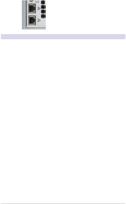
1.6.2 Rear panel LEDs
|
|
|
|
|
ACT/LINK LED |
|
|
|
|
|
|
SPEED LED |
|
|
|
|
|
|||
|
|
|
|
|
ACT/LINK LED |
|
|
|
|
|
|
||
|
|
|
|
|
SPEED LED |
|
|
|
|
|
|
||
|
|
|
|
|
|
|
ACT/LINK LED |
SPEED LED |
|
|
|
||
Status |
Description |
Status |
|
|
Description |
|
OFF |
No link |
OFF |
|
|
10Mbps connection |
|
Green |
Linked |
Orange |
|
|
100Mbps connection |
|
Blinking |
Data activity |
Green |
|
|
1000Mbps connection |
|
1-10 |
Chapter 1: Product introduction |
Chapter 2
This chapter lists the hardware setup procedures that you have to perform when installing or removing system components.
Hardware setup
ASUS TS500-E4 |
2- |
2.1 Chassis cover
The chassis features a “screwless design” that allows convenient assembly and disassembly. You can simply push or slide mechanical bolts and locks to remove the cover.
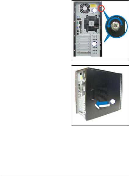
2.1.1 Removing the side cover
1. Remove the two screws that secure the cover to the chassis.
1
1 
2.Slide the side cover for about half an inch toward the rear until it is disengaged from the chassis.
3.Carefully lift the cover and set it aside.
2
Viewing the internal structure
Without the side cover, the internal structure and installed components of the barebone server vary depending on the model you purchased. Refer to section “1.5 Internal features” for the different model configurations.
Perform the procedures in the succeeding sections to install the CPU, system memory, disk drives, and expansion cards; replace fans and power supply; and connect the system cables.
2- |
Chapter 2: Hardware setup |
You may need to remove some of the installed components to access the DIMM sockets and internal connectors. Refer to section “2.10 Removable components” for instructions.
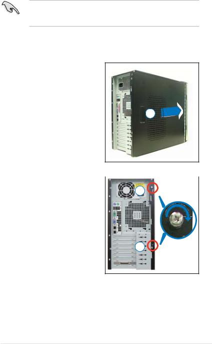
2.1.2 Reinstalling the side cover
To reinstall the side cover:
1.Match and insert the upper hooks and lower sliding edge of the cover to the corresponding chassis holes and edge.
2.Slide the cover toward the front until it snaps in place.
2
3. Drive in the two screws you |
|
|
removed earlier to secure the side |
3 |
|
cover. |
||
|
3
ASUS TS500-E4 |
2- |
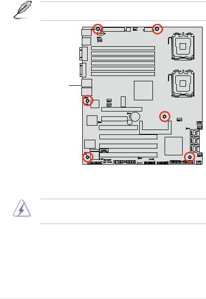
2.2 Motherboard information
The barbone server comes with the DSBV-D motherboard already installed. The motherboard is secured to the chassis by six (6) screws as indicated by the circles in the illustration below.
Refer to "Chapter 4 Motherboard information" for detailed information on the motherboard.
DSBV-D |
Place this side towards |
the rear of the chassis |
Make sure to unplug the chassis power cord before installing or removing the motherboard. Failure to do so can cause you physical injury and damage motherboard components!
2- |
Chapter 2: Hardware setup |
2.3 Central Processing Unit (CPU)
The motherboard comes with a surface mount LGA771 socket designed for the Intel® Xeon® Dual Core processor.
•Your boxed Intel® Xeon® LGA771 processor package should
come with installation instructions for the CPU and heatsink. If the instructions in this section do not match the CPU documentation, follow the latter.
•Upon purchase of the motherboard, make sure that the PnP cap is on the socket and the socket contacts are not bent. Contact your retailer immediately if the PnP cap is missing, or if you see any damage to the PnP cap/socket contacts/motherboard components. ASUS will shoulder the cost of repair only if the damage is shipment/ transit-related.
•Keep the cap after installing the motherboard. ASUS will process
Return Merchandise Authorization (RMA) requests only if the motherboard comes with the cap on the LGA771 socket.
•The product warranty does not cover damage to the socket contacts resulting from incorrect CPU installation/removal, or misplacement/ loss/incorrect removal of the PnP cap.
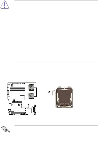
2.3.1 Installing the CPU
To install a CPU:
1. Locate the CPU socket on the motherboard.
DSBV-D
CPU1
CPU2
DSBV-D CPU LGA771
Before installing the CPU, make sure that the socket box is facing towards you and the load lever is on your left.
ASUS TS500-E4 |
2- |

2.Press the load lever with your thumb (A), then move it to the left (B) until it is released from the retention tab.
Retention tab
A
Load lever
|
|
|
PnP cap |
B |
|
||
|
|
||
|
|
||
This side of the socket |
|||
|
|
box should face you. |
|
To prevent damage to the socket pins, do not remove the PnP cap unless you are installing a CPU.
3.Lift the load lever in the direction of the arrow to a 135º angle.
4.Lift the load plate with your thumb
and forefinger to a 100º angle (A), |
B |
then push the PnP cap from the |
|
load plate window to remove (B). |
A |
|
|
|
Load plate |
5.Position the CPU over the socket, making sure that the gold triangle is on the bottom-left corner of the socket. The socket alignment key should fit into the CPU notch.
Alignment key
Gold triangle mark
2- |
Chapter 2: Hardware setup |

6. Close the load plate (A), then |
A |
push the load lever (B) until it |
|
snaps into the retention tab. |
|
|
B |
The CPU fits in only one correct orientation. DO NOT force the CPU into the socket to prevent bending the connectors on the socket and damaging the CPU!
Notes on Intel® Hyper-Threading Technology
•This motherboard supports Intel® Xeon™ CPUs in the 771 land package with Hyper-Threading Technology.
•Hyper-Threading Technology is supported by Intel® 5000 series CPU only. 5100 series DO NOT support Hyper-Threading.
•Hyper-Threading Technology is supported under Windows® XP/2003 Server and Linux 2.4.x (kernel) and later versions only. Under Linux, use the Hyper-Threading compiler to compile the code. If you are using any other operating systems, disable the Hyper-Threading Technology item in the BIOS to ensure system stability and performance.
•Installing Windows® 2003 Server or later version is recommended.
•Make sure to enable the Hyper-Threading Technology item in BIOS before installing a supported operating system.
•For more information on Hyper-Threading Technology, visit www. intel.com/info/hyperthreading.
To use the Hyper-Threading Technology on this motherboard:
1.Install an Intel® Xeon™ CPU that supports Hyper-Threading Technology.
2.Power up the system and enter the BIOS Setup (see Chapter 5: BIOS information). Under the Advanced Menu, make sure that the item Hyper Threading Technology is set to Enabled. The item appears only if you installed a CPU that supports Hyper-Threading Technology.
3.Reboot the computer.
ASUS TS500-E4 |
2- |

2.3.2 Installing the CPU heatsink and fan
The Intel® Xeon™ processors require an Intel certified or ASUS qualified heatsink and fan assembly to ensure optimum thermal condition and performance.
When you buy a boxed Intel CPU, the package includes the heatsink, fan, retention brackets, screws, thermal grease, installation manual, and other items that are necessary for CPU installation.
• Make sure that you have applied the thermal grease to the top of the CPU before installing the heatsink and fan.
•Refer to the installation manual that came with the CPU package for details on heatsink/fan assembly and installation.
•For installation instruction of optional ASUS qualified CPU heatsink and fan assembly, refer to section 3.2.
CPU heatsink (top view) |
CPU heatsink (bottom view) |
|||
|
|
|
|
|
|
|
|
|
|
|
|
|
|
|
|
|
|
|
|
Heatsink screw
Before installing the CPU heatsinks, ensure that the jumpers DIP_SW1 are set correctly depending on the pin definition of your CPU fan cables.
Refer to page 4-8 for information on these jumpers.
To install the CPU heatsink and fan:
1.Place the heatsink on top of the installed CPU, making sure that the four screws on the heatsink align with the nuts on the support plate.
2- |
Chapter 2: Hardware setup |
 Loading...