

Page 1

RS620SA-E10
2U Rackmount Server
User Guide
Page 2

E16899
First Edition
September 2020
Copyright © 2020 ASUSTeK COMPUTER INC. All Rights Reserved.
No part of this manual, including the products and software described in it, may be reproduced, transmitted,
transcribed, stored in a retrieval system, or translated into any language in any form or by any means,
except documentation kept by the purchaser for backup purposes, without the express written permission
of ASUSTeK COMPUTER INC. (“ASUS”).
ASUS provides this manual “as is” without warranty of any kind, either express or implied, including but not
limited to the implied warranties or conditions of merchantability or fitness for a particular purpose. In no
event shall ASUS, its directors, officers, employees, or agents be liable for any indirect, special, incidental,
or consequential damages (including damages for loss of profits, loss of business, loss of use or data,
interruption of business and the like), even if ASUS has been advised of the possibility of such damages
arising from any defect or error in this manual or product.
Specifications and information contained in this manual are furnished for informational use only, and are
subject to change at any time without notice, and should not be construed as a commitment by ASUS.
ASUS assumes no responsibility or liability for any errors or inaccuracies that may appear in this manual,
including the products and software described in it.
Product warranty or service will not be extended if: (1) the product is repaired, modified or altered, unless
such repair, modification of alteration is authorized in writing by ASUS; or (2) the serial number of the
product is defaced or missing.
Products and corporate names appearing in this manual may or may not be registered trademarks or
copyrights of their respective companies, and are used only for identification or explanation and to the
owners’ benefit, without intent to infringe.
ii
Page 3

Contents
Safety information ..................................................................................................... vii
About this guide ......................................................................................................... ix
Chapter 1: Product Introduction
1.1 System package contents ......................................................................... 1-2
1.2 Serial number label .................................................................................... 1-2
1.3 System specifications ...............................................................................1-3
1.4 Front panel features ...................................................................................1-5
1.5 Rear panel features .................................................................................... 1-6
1.6 Internal features ......................................................................................... 1-7
1.7 LED information ......................................................................................... 1-8
1.7.1 Front panel LEDs ........................................................................1-8
1.7.2 Storage device status LED..........................................................1-9
1.7.3 LAN (RJ-45) LEDs ......................................................................1-9
1.7.4 Q-Code table .............................................................................1-10
Chapter 2: Hardware Information
2.1 Chassis cover ............................................................................................. 2-2
2.2 Central Processing Unit (CPU) .................................................................2-3
2.2.1 Installing the CPU and heatsink ..................................................2-3
2.3 System memory .........................................................................................2-7
2.3.1 Overview ..................................................................................... 2-7
2.3.2 Memory Configurations ...............................................................2-8
2.3.3 Installing a DIMM on a single clip DIMM socket..........................2-9
2.3.4 Removing a DIMM from a single clip DIMM socket ....................2-9
2.4 Storage devices........................................................................................2-10
2.5 Expansion slot ..........................................................................................2-11
2.5.1 Installing an expansion card to riser card..................................2-12
2.5.2 Configuring an expansion card .................................................2-14
2.5.3 Installing Mezzanine cards ........................................................2-15
2.5.4 Installing M.2 (NGFF) cards ......................................................2-18
2.6 Removable/optional components ...........................................................2-20
2.6.1 System fans ..............................................................................2-20
2.6.2 Redundant power supply module..............................................2-22
2.7 Cable management .................................................................................. 2-23
iii
Page 4

Contents
Chapter 3: Installation Options
3.1 Tool-less Friction Rail Kit .......................................................................... 3-2
3.2 Installing the tool-less rack rail ................................................................3-3
3.3 Rail kit dimensions ....................................................................................3-5
Chapter 4: Motherboard Information
4.1 Motherboard layout ....................................................................................4-2
4.1.1 Layout contents ...........................................................................4-3
4.2 Jumpers ...................................................................................................... 4-4
4.3 Internal connectors .................................................................................... 4-7
4.4 Internal LEDs ............................................................................................ 4-10
Chapter 5: BIOS Setup
5.1 Managing and updating your BIOS .......................................................... 5-2
5.1.1 ASUS CrashFree BIOS 3 utility...................................................5-2
5.1.2 ASUS EZ Flash Utility .................................................................5-3
5.1.3 BUPDATER utility .......................................................................5-4
5.2 BIOS setup program .................................................................................. 5-6
5.2.1 BIOS menu screen ......................................................................5-7
5.2.2 Menu bar .....................................................................................5-7
5.2.3 Menu items..................................................................................5-8
5.2.4 Submenu items ...........................................................................5-8
5.2.5 Navigation keys ...........................................................................5-8
5.2.6 General help................................................................................5-8
5.2.7 Configuration fields .....................................................................5-8
5.2.8 Pop-up window............................................................................5-8
5.2.9 Scroll bar .....................................................................................5-8
5.3 Main menu ..................................................................................................5-9
5.3.1 System Date [Day xx/xx/xxxx] .....................................................5-9
5.3.2 System Time [xx:xx:xx] ...............................................................5-9
5.4 Performance Tuning menu ......................................................................5-10
iv
Page 5

Contents
5.5 Advanced menu .......................................................................................5-11
5.5.1 Trusted Computing....................................................................5-12
5.5.2 PSP Firmware Versions ............................................................5-12
5.5.3 APM Configuration ....................................................................5-12
5.5.4 Onboard LAN Configuration ......................................................5-13
5.5.5 Serial Port Console Redirection ................................................5-14
5.5.6 CPU Configuration ....................................................................5-17
5.5.7 PCI Subsystem Settings ...........................................................5-18
5.5.8 USB Configuration ....................................................................5-19
5.5.9 Network Stack Configuration.....................................................5-20
5.5.10 CSM Configuration .................................................................... 5-21
5.5.11 SATA Configuration .................................................................. 5-22
5.5.12 NVMe Configuration .................................................................. 5-22
5.5.13 AMD Mem Configuration Status................................................ 5-23
5.5.14 iSCSI Configuration...................................................................5-23
5.6 Chipset menu ...........................................................................................5-24
5.7 Security menu ..........................................................................................5-25
5.8 Boot menu ................................................................................................5-29
5.9 Tool menu ................................................................................................. 5-30
5.10 Save & Exit menu ..................................................................................... 5-31
5.11 AMD CBS menu ........................................................................................ 5-32
5.11.1 CPU Common Options.............................................................. 5-32
5.11.2 DF Common Options ................................................................ 5-34
5.11.3 UMC Common Option ............................................................... 5-36
5.11.4 NBIO Common Options ............................................................ 5-41
5.11.5 NTB Common Options .............................................................. 5-45
5.12 Event Logs menu ..................................................................................... 5-46
5.12.1 Change Smbios Event Log Settings ......................................... 5-46
5.12.2 View Smbios Event Log ............................................................ 5-47
5.13 Server Mgmt menu ................................................................................... 5-48
v
Page 6

Contents
Chapter 6: Driver Installation
6.1 Management applications and utilities installation ................................ 6-2
6.2 Running the Support DVD ......................................................................... 6-2
6.2.1 Drivers menu tab .........................................................................6-3
6.2.2 Utilities menu tab.........................................................................6-3
6.2.3 Manual menu ..............................................................................6-4
6.3 AMD chipset device software installation ...............................................6-5
6.4 Installing the Intel® I210 Gigabit Network Connections .........................6-6
6.5 VGA driver installation ..............................................................................6-8
Appendix
KRPH-U8 block diagram ......................................................................................... A-2
Notices .................................................................................................................... A-3
ASUS contact information ...................................................................................... A-7
vi
Page 7

Safety information
Electrical Safety
• Before installing or removing signal cables, ensure that the power cables for the system
unit and all attached devices are unplugged.
• To prevent electrical shock hazard, disconnect the power cable from the electrical outlet
before relocating the system.
• When adding or removing any additional devices to or from the system, ensure that the
power cables for the devices are unplugged before the signal cables are connected. If
possible, disconnect all power cables from the existing system before you add a device.
• If the power supply is broken, do not try to fix it by yourself. Contact a qualified service
technician or your dealer.
Operation Safety
• Any mechanical operation on this server must be conducted by certified or experienced
engineers.
• Before operating the server, carefully read all the manuals included with the server
package.
• Before using the server, ensure all cables are correctly connected and the power cables
are not damaged. If any damage is detected, contact your dealer as soon as possible.
• To avoid short circuits, keep paper clips, screws, and staples away from connectors,
slots, sockets and circuitry.
• Avoid dust, humidity, and temperature extremes. Place the server on a stable surface.
• If you encounter technical problems with the product, contact a qualified service
technician or your retailer.
This product is equipped with a three-wire power cable and plug for the user’s safety. Use
the power cable with a properly grounded electrical outlet to avoid electrical shock.
vii
Page 8

Restricted Access Location
This product is intended for installation only in a Computer Room where:
• Access can only be gained by SERVICE PERSONS or by USERS who have been
instructed about the reasons for the restrictions applied to the location and about any
precautions that shall be taken.
• Access is through the use of a TOOL, or other means of security, and is controlled by the
authority responsible for the location.
Lithium-Ion Battery Warning
CAUTION! Danger of explosion if battery is incorrectly replaced. Replace
only with the same or equivalent type recommended by the manufacturer.
Dispose of used batteries according to the manufacturer’s instructions.
Heavy System
CAUTION! This server system is heavy. Ask for assistance when moving
or carrying the system.
viii
Page 9

About this guide
Audience
This user guide is intended for system integrators, and experienced users with at least basic
knowledge of configuring a server.
Contents
This guide contains the following parts:
1. Chapter 1: Product Introduction
This chapter describes the general features of the server, including sections on front
panel and rear panel specifications.
2. Chapter 2: Hardware Information
This chapter lists the hardware setup procedures that you have to perform when
installing or removing system components.
3. Chapter 3: Installation Options
This chapter describes how to install optional components into the barebone server.
4. Chapter 4: Motherboard Information
This chapter gives information about the motherboard that comes with the server. This
chapter includes the motherboard layout, jumper settings, and connector locations.
5. Chapter 5: BIOS Setup
This chapter tells how to change system settings through the BIOS Setup menus and
describes the BIOS parameters.
6. Chapter 6: Driver Installation
This chapter provides instructions for installing the necessary drivers for different
system components.
ix
Page 10

Conventions
To ensure that you perform certain tasks properly, take note of the following symbols used
throughout this manual.
DANGER/WARNING:
complete a task.
CAUTION:
trying to complete a task.
IMPORTANT:
NOTE:
Information to prevent damage to the components when
Tips and additional information to help you complete a task.
Information to prevent injury to yourself when trying to
Instructions that you MUST follow to complete a task.
Typography
Bold text
Italics
<Key> Keys enclosed in the less-than and greater-than sign
Example: <Enter> means that you must press the Enter
<Key1>+<Key2>+<Key3> If you must press two or more keys simultaneously, the
Example: <Ctrl>+<Alt>+<Del>
Command
Example: At the DOS prompt, type the command line:
Indicates a menu or an item to select.
Used to emphasize a word or a phrase.
means that you must press the enclosed key.
or Return key.
key names are linked with a plus sign (+).
Means that you must type the command exactly as
shown, then supply the required item or value enclosed in
brackets.
format A:/S
References
Refer to the following sources for additional information, and for product and software
updates.
1. ASUS Control Center (ACC) user guide
This manual tells how to set up and use the proprietary ASUS server management
utility. Visit asuscontrolcenter.asus.com for more information.
2. ASUS websites
The ASUS websites worldwide provide updated information for all ASUS hardware and
software products. Refer to the ASUS contact information.
x
Page 11

Chapter 1: Product Introduction
Product Introduction
This chapter describes the general features of the chassis kit. It
includes sections on front panel and rear panel specifications.
1
Page 12
1.1 System package contents
Check your system package for the following items.
Model Name
Chassis
Motherboard
Component
Accessories
Optional Items
RS620SA-E10-RS12
ASUS 2U Rackmount Chassis
ASUS KRPH-U8 Server Board
2 x 2200W/3000W 80PLUS Platinum Power Supply
12 x Hot-swap 2.5-inch Storage Device Trays
4 x System Fans
2 x Rear Midplane Board (MP4LE-D-R2HC-PL1)
2 x Front Midplane Board (MP2LE-D-R2HC-PL1)
6 x Converter Board (CB8LX12G-R2H-B)
6 x Rear PCIe Riser Card (RG16L-R2HC-A/B/C)
6 x M.2 Riser Card (RG4RG4L-M2X2-R2HC)
1 x Power Connection Board (PSB-R2HC-PL2)
2 x Front Panel Board (FPB-R2HC-R/L-PL2)
1 x Backplane Board (BP12LE12G-25-R2HC)
1 x Support DVD
1 x Bag of Screws
6 x CPU Heatsink
2 x AC Power Cable
1 x Friction Rail Kit
If any of the above items is damaged or missing, contact your retailer.
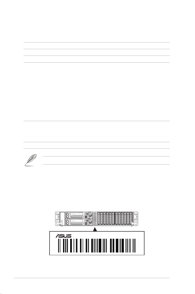
1.2 Serial number label
The product’s serial number contains 12 characters such as xxS0xxxxxxxx and printed on the
sticker at the server's front cover.
The correct serial number of the product is required if you need to request for support from
the ASUS Technical Support team.
1-2
RS620SA-E10-RS12
xxS0xxxxxxxx
Chapter 1: Product Introduction
Page 13

1.3 System specifications
The ASUS RS620SA-E10 Series feature the ASUS KRPH-U8 server board. The server
supports AMD EPYC™ Rome Processors plus other latest technologies through the chipsets
onboard.
Model Name RS620SA-E10-RS12
Motherboard
Processor Support
Core Logic
Memory
Expansion Slots
Disk Controller
Storage Bays
M.2 (NGFF) Support
Networking
Graphic
Remote Management
KRPH-U8
Per Node: 1 x Socket
AMD EPYC™ Rome Processors
System on Chip (SoC)
Per Node:
8 x DDR4 3200/2933/2666 RDIMM/LR-DIMM/LR-DIMM 3DS
Per Node:
1 x PCIe x16 (Gen4 x16 link), LP, HL
1 x OCP Mezzanine 3.0 (Gen4 x16 link)
Internal SATA/SAS converter board
Broadcom (LSI) SAS3008
Per Node:
2 x 2.5” 15mm hot-swap storage bays
(2 x SATA/SAS or 2 x NVMe supported)
Per Node:
2 x M.2 Gen4 x4 link, up to 22110 (PCIe & SATA supported)
Per Node:
1 x 1GbE LAN (i210 Chipset)
1 x Management Port (AST2500)
Aspeed AST2500 64MB
ASUS Control Center (ASWM Enterprise 2.0)
ASMB9-iKVM for KVM-over-IP (On-Board)
(continued on the next page)
ASUS RS620SA-E10-RS12
1-3
Page 14
Model Name RS620SA-E10-RS12
I/O Ports (per Node):
2 x USB 3.2 Gen 1 ports
1 x VGA port
1 x RJ-45 1GbE LAN port
1 x RJ-45 Mgmt LAN port
Switch/LED (per Node):
1 x Power switch/LED
I/O ports, Switches, and LEDs
Security Options
Out of Band
Management
Solution
OS Support
Regulatory Compliance
Dimension
(Depth x Width x Height)
Net Weight Kg (CPU, DRAM &
storage device not included)
Gross Weight Kg (CPU, DRAM
& storage device not included,
packing included)
Power Supply
(different configuration
by region)
Environment
* Specifications are subject to change without notice.
Remote
Hardware
Software
1 x Q-Code/Port 80 LED
1 x Message LED
1 x Location switch/LED
Switch/LED (front panel):
4 x Power switch/LED (Node 1-4 only)
4 x Message LED (Node 1-4 only)
4 x LAN LED (Node 1-4 only)
6 x Location switch/LED
TPM 2.0 Header
On-Board ASMB9-iKVM for KVM-over-IP
ASUS Control Center (Classic)
Please find the latest OS support from http://www.asus.com
BSMI, CE, FCC(Class A)
846.2 mm x 444 mm x 88 mm (2U)
36.99 Kg
46.68 Kg
2 x 2200W/3000W 80PLUS Platinum Power Supply
Rating: 200-240Vac, 12.6A (x2), 47-63Hz
Rating: 220-240Vac, 15.5A (x2), 50/60Hz
Operating temperature: 10°C ~ 35°C
Non operating temperature: -40°C ~ 70°C
Non operating humidity: 20% ~ 90% (Non condensing)
1-4
Chapter 1: Product Introduction
Page 15
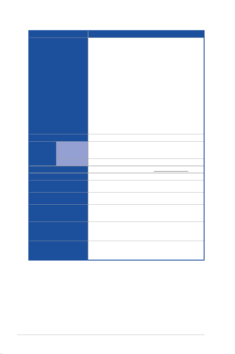
1.4 Front panel features
Refer to section 1.7 LED information for the LED descriptions.
RS620SA-E10-RS12
Front panel LEDs & buttons
Node 6
Front panel LEDs & buttons
handle
Node
Node 5
VGA portMgmt LAN port*
Gigabit LAN port
12 x 2.5” Storage Bays
Power button
Q-Code LED
USB 3.2 Gen 1 ports
• * This port is for ASUS ASMB9-iKVM only.
• The Q-Code LED provides the most probable cause of an error code as a starting
point for troubleshooting. The actual cause may vary from case to case.
• Refer to the Q-Code table for details.
handle
ASUS RS620SA-E10-RS12
1-5
Page 16
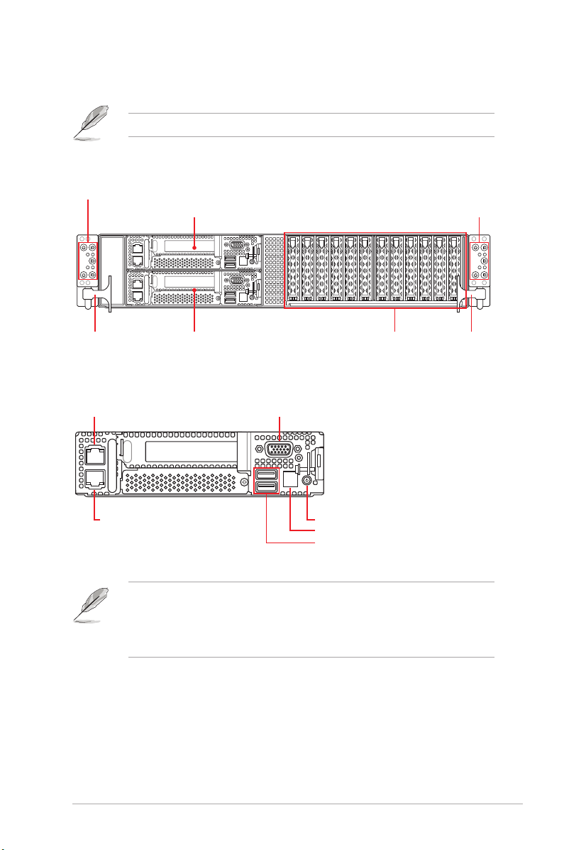
1.5 Rear panel features
RS620SA-E10-RS12
Redundant power supply Node 4
Node 3 Node 1
Node
Gigabit LAN port
Node 2
VGA portMgmt LAN port*
Power button
Q-Code LED
USB 3.2 Gen 1 ports
1-6
• * This port is for ASUS ASMB9-iKVM only.
• The Q-Code LED provides the most probable cause of an error code as a starting
point for troubleshooting. The actual cause may vary from case to case.
• Refer to the Q-Code table for details.
Chapter 1: Product Introduction
Page 17
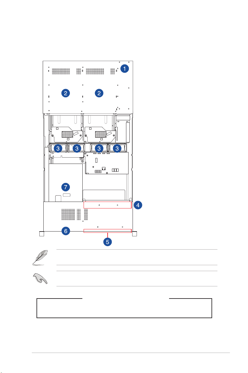
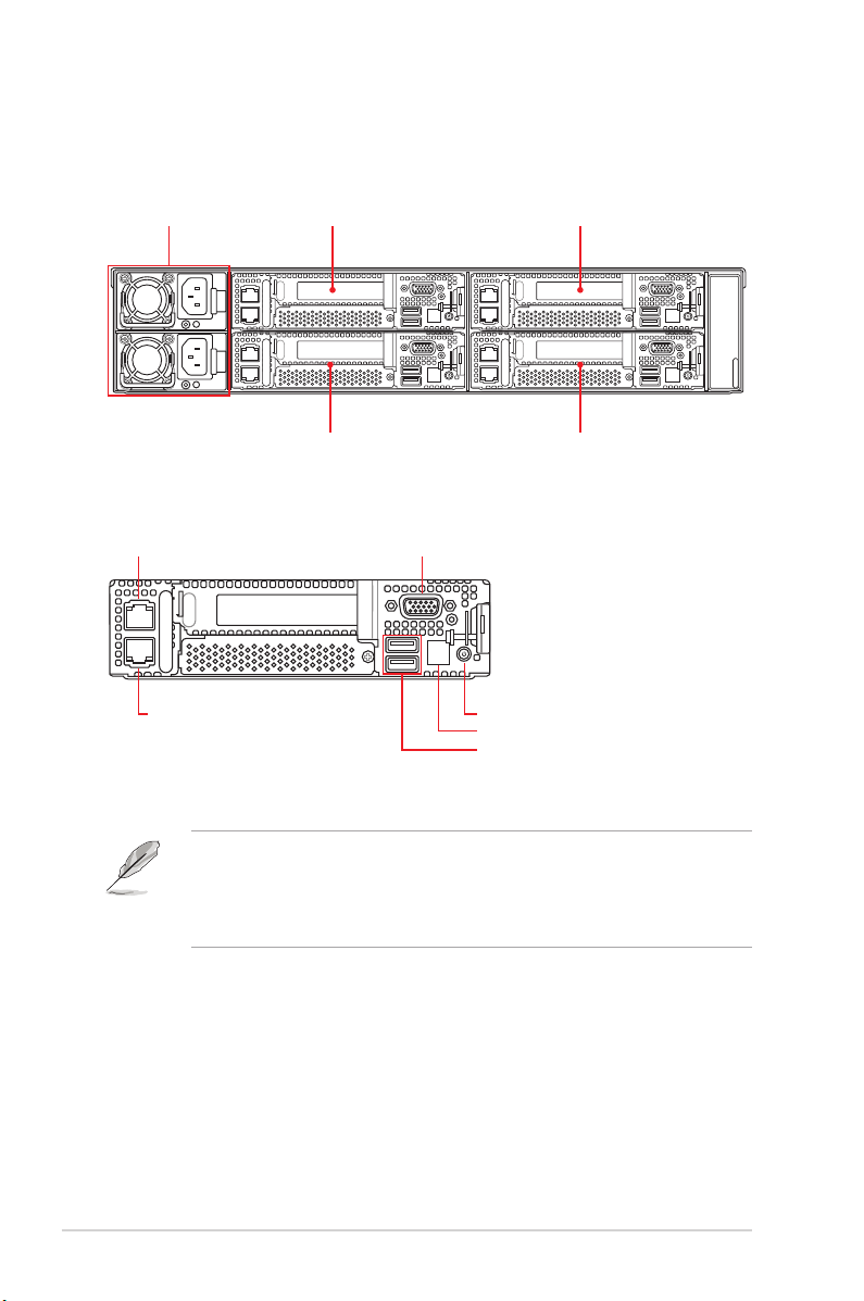
1.6 Internal features
The barebone server includes the basic components as shown.
1. Redundant Power supply
2. ASUS KRPH-U8 Server
Board (Node 1-4)
3. System fans
4. Backplane Board
(BP12LE12G-25-R2HC)
5. 12 x 2.5” storage device trays
6. Front panel (hidden)
7. ASUS KRPH-U8 Server
Board (Node 5-6)
The barebone server does not include a floppy disk drive. Connect a USB floppy disk drive to
any of the USB ports on the front or rear panel if you need to use a floppy disk.
A protection film is pre-attached to the front cover before shipping. Please remove the
protection film before turning on the system for proper heat dissipation.
KEEP FINGERS AND OTHER BODY PARTS AWAY
ASUS RS620SA-E10-RS12
HAZARDOUS MOVING PARTS
WARNING
1-7
Page 18
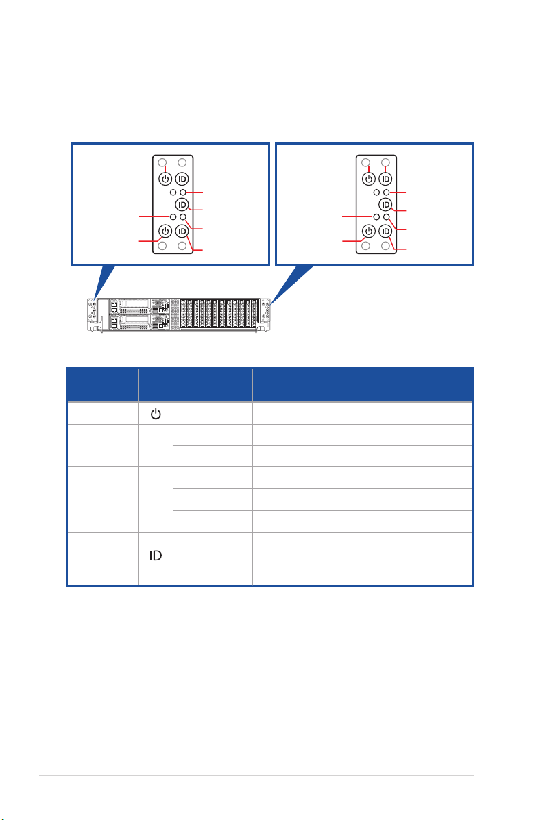
1.7 LED information
1.7.1 Front panel LEDs
Node 2
Power button
Node 2
Message LED
Node 1
Message LED
Node 1
Power button
Node 2
Location button
Node 2 LAN LED
Node 5
Location button
Node 1 LAN LED
Node 1
Location button
Node 4
Power button
Node 4
Message LED
Node 3
Message LED
Node 3
Power button
LED Icon Display status Description
Power LED ON System power ON
Message LED
OFF System is normal; no incoming event
ON A hardware monitor event is indicated
OFF No LAN connection
LAN LED
Blinking LAN is transmitting or receiving data
ON LAN connection is present
ON Location switch is pressed
Location LED
OFF
Normal status (Press the location button again
to turn off)
Node 4
Location button
Node 4 LAN LED
Node 6
Location button
Node 3 LAN LED
Node 3
Location button
1-8
Chapter 1: Product Introduction
Page 19
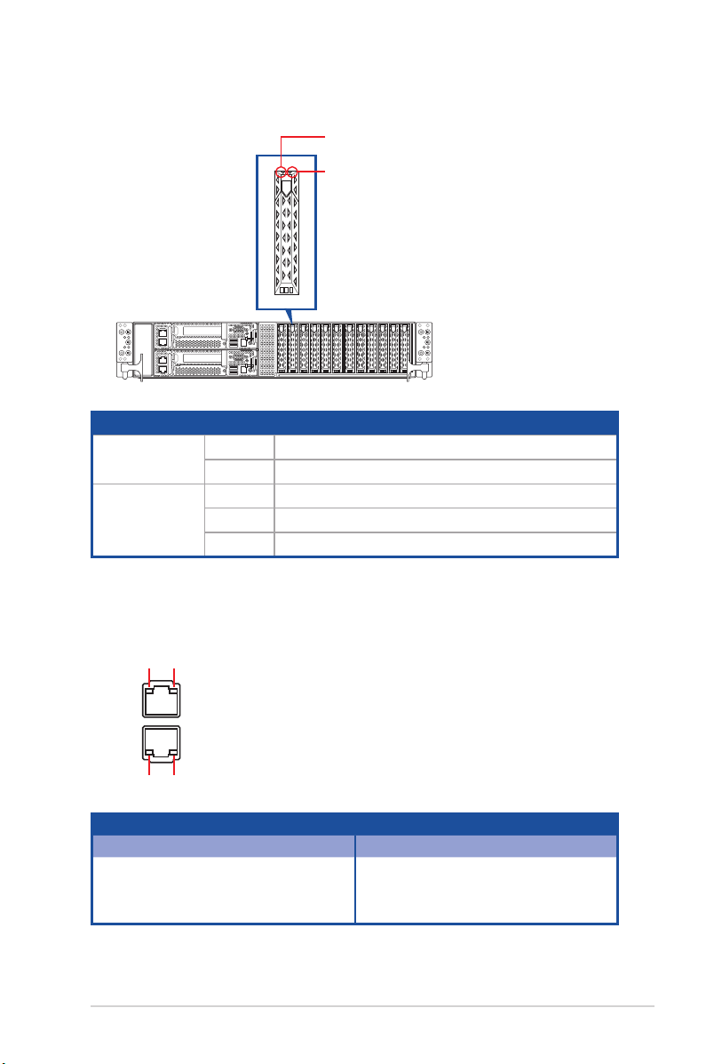
1.7.2 Storage device status LED
Red LED
Green LED
Storage Device LED Description
Status (RED)
Activity (GREEN)
ON Storage device has failed
Blinking RAID rebuilding or locating
ON Storage device power ON
Blinking Read/write data from/into the SATA/SAS storage device
OFF Storage device not found
1.7.3 LAN (RJ-45) LEDs
ACT/LINK LED SPEED LED
ACT/LINK LED SPEED LED
ACT/LINK LED SPEED LED
Status Description Status Description
OFF No link OFF 10 Mbps connection
GREEN Linked ORANGE 100 Mbps connection
BLINKING Data activity GREEN 1 Gbps connection
ASUS RS620SA-E10-RS12
1-9
Page 20

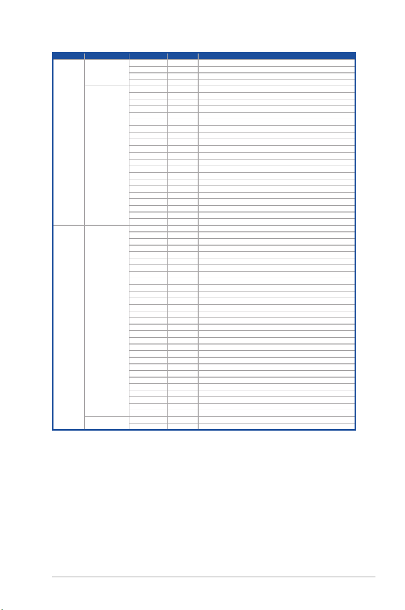
1.7.4 Q-Code table
Action PHASE POST CODE TYPE DESCRIPTION
SEC Start
up
PSP Boot
Security Phase
PSP Boot Loader
phase (Error Post
Codes)
0x01 Progress First post code
0x02 Progress Load BSP microcode
0x03 Progress Perform early platform Initialization
0x04 Progress Set cache as ram for PEI phase
0x05 Progress Establish Stack
0x06 Progress CPU Early Initialization
0x00 Error General - Success
0x01 Error Generic Error Code
0x02 Error Generic Memory Error
0x03 Error Buffer Overflow
0x04 Error Invalid Parameter(s)
0x05 Error Invalid Data Length
0x06 Error Data Alignment Error
0x07 Error Null Pointer Error
0x08 Error Unsupported Function
0x09 Error Invalid Service ID
0x0A Error Invalid Address
0x0B Error Out of Resource Error
0x0C Error Timeout
0x0D Error data abort exception
0x0E Error prefetch abort exception
0x0F Error Out of Boundary Condition Reached
0x10 Error Data corruption
0x11 Error Invalid command
0x12 Error The package type provided by BR is incorrect
0x13 Error Failed to retrieve FW header during FW validation
0x14 Error Key size not supported
0x15 Error Agesa0 verification error
0x16 Error SMU FW verification error
0x17 Error OEM SINGING KEY verification error
0x18 Error Generic FW Validation error
0x19 Error RSA operation fail - bootloader
0x1A Error CCP Passthrough operation failed - internal status
0x1B Error AES operation fail
0x1C Error CCP state save failed
0x1D Error CCP state restore failed
0x1E Error SHA256 operation fail - internal status
0x1F Error ZLib Decompression operation fail
0x20 Error HMAC-SHA256 operation fail - internal status
0x21 Error Booted from boot source not recognized by PSP
0x22 Error PSP directory entry not found
0x23 Error PSP failed to set the write enable latch
0x24 Error PSP timed out because spirom took too long
0x25 Error Cannot find BIOS directory
0x26 Error SpiRom is not valid
0x27 Error slave die has different security state from master
0x28 Error SMI interface init failure
0x29 Error SMI interface generic error
0x2A Error invalid die ID executes MCM related function
0x2B Error invalid MCM configuration table read from bootrom
0x2C Error Valid boot mode wasn't detected
0x2D Error NVStorage init failure
0x2E Error NVStorage generic error
0x2F Error MCM 'error' to indicate slave has more data to send
0x30 Error MCM error if data size exceeds 32B
0x31 Error Invalid client id for SVC MCM call
0x32 Error MCM slave status register contains bad bits
0x33 Error MCM call was made in a single die environment
0x34 Error PSP secure mapped to invalid segment (should be 0x400_0000)
0x35 Error No physical x86 cores were found on die
0x36 Error Insufficient space for secure OS (range of free SRAM to SVC stack base)
0x37 Error SYSHUB mapping memory target type is not supported
0x38 Error Attempt to unmap permanently mapped TLB to PSP secure region
(continued on the next page)
1-10
Chapter 1: Product Introduction
Page 21

Action PHASE POST CODE TYPE DESCRIPTION
PSP Boot
PSP Boot Loader
phase (Error Post
Codes)
0x39 Error Unable to map an SMN address to AXI space
0x3A Error Unable to map a SYSHUB address to AXI space
0x3B Error The count of CCXs or cores provided by bootrom is not consistent
0x3C Error Uncompressed image size doesn't match value in compressed header
0x3D Error Compressed option used in case where not supported
0x3E Error Fuse info on all dies don't match
0x3F Error PSP sent message to SMU; SMU reported an error
0x40 Error Function RunPostX86ReleaseUnitTests failed in memcmp()
0x41 Error Interface between PSP to SMU not available.
0x42 Error Timer wait parameter too large
0x43 Error Test harness module reported an error
0x44 Error x86 wrote C2PMSG_0 interrupting PSP
0x45 Error A write to an L3 register failed
0x46 Error Mini-BL
0x47 Error Mini-BL CCP HMAC Unit-test failed
0x48 Error Potential stack corruption in jump to Mini BL
0x49 Error Error in Validate and Loading AGESA APOB SVC call
0x4A Error Correct fuse bits for DIAG_BL loading not set
0x4B Error The UmcProgramKeys() function was not called by AGESA
0x4C Error Secure unlock error
0x4D Error Syshub register programming mismatch during readback
0x4E Error Family ID in MP0_SFUSE_SEC[7:3] not correct
0x4F Error An operation was invoked that can only be performed by the GM
0x50 Error Failed to acquire host controller semaphore to claim ownership of SMB
0x51 Error Timed out waiting for host to complete pending transactions
0x52 Error Timed out waiting for slave to complete pending transactions
0x53 Error Unable to kill current transaction on host
0x54 Error One of: Illegal command
0x55 Error An SMBus transaction collision detected
0x56 Error Transaction failed to be started or processed by host
0x57 Error An unsolicited SMBus interrupt was received
0x58 Error An attempt to send an unsupported PSP-SMU message was made
0x59 Error An error/data corruption detected on response from SMU for sent msg
0x5A Error MCM Steady-state unit test failed
0x5B Error S3 Enter failed
0x5C Error AGESA BL did not set PSP SMU reserved addresses via SVC call
0x5E Error CcxSecBisiEn not set in fuse RAM
0x5F Error Received an unexpected result
0x60 Error VMG Storage Init failed
0x61 Error Failure in mbedTLS user app
0x62 Error An error occured whilst attempting to SMN map a fuse register
0x63 Error Fuse burn sequence/operation failed due to internal SOC error
0x64 Error Fuse sense operation timed out
0x65 Error Fuse burn sequence/operation timed out waiting for burn done
0x66 Error Failure status indicating that the given SecureOS has been
0x67 Error This PSP FW was revoked
0x68 Error
0x69 Error The BIOS OEM public key of the BIOS was revoked for this platform
0x6A Error PSP level 2 directory not match expected value.
0x6B Error BIOS level 2 directory not match expected value.
0x6C Error
0x6D Error Generic error indicating the CCP HAL initialization failed
0x94 Error Knoll failed to idle correctly after being reset
0x95 Error Bad status returned by I2CKnollCheck
0x96 Error NACK to general call (no device on Knoll I2C bus)
0x97 Error Null pointer passed to I2CKnollCheck
0x98 Error Invalid device-ID found during Knoll authentication
0x99 Error Error during Knoll/Prom key derivation
0x9A Error Null pointer passed to Crypto function
0x9B Error Error in checksum from wrapped Knoll/Prom keys
0x9C Error Knoll returned an invalid response to a command
0x9D Error Bootloader failed in Knoll Send Command function
0x9E Error No Knoll device found by verifying MAC
The platform model/vendor id fuse is not matching the BIOS public key
token
HVB validation failure for BIOS RTM volume (OEM public/signature failed
to validate).
(continued on the next page)
ASUS RS620SA-E10-RS12
1-11
Page 22

Action PHASE POST CODE TYPE DESCRIPTION
PSP Boot
PSP Boot Loader
phase (Status Post
Codes)
0xA0 Progress Bootloader successfully entered C Main
0xA1 Progress Master initialized C2P / slave waited for master to init C2P
0xA2 Progress HMAC key successfully derived
0xA3 Progress Master got Boot Mode and sent boot mode to all slaves
0xA4 Progress SpiRom successfully initialized
0xA5 Progress BIOS Directory successfully read from SPI to SRAM
0xA6 Progress Early unlock check
0xA7 Progress Inline Aes key successfully derived
0xA8 Progress Inline-AES key programming is done
0xA9 Progress Inline-AES key wrapper derivation is done
0xAA Progress Bootloader successfully loaded HW IP configuration values
0xAB Progress Bootloader successfully programmed MBAT table
0xAC Progress Bootloader successfully loaded SMU FW
0xAD Progress PSP and SMU configured WAFL
0xAE Progress User mode test harness completed successfully
0xAF Progress Bootloader loaded Agesa0 from SpiRom
0xB0 Progress AGESA phase has completed
0xB1 Progress RunPostDramTrainingTests() completed successfully
0xB2 Progress SMU FW Successfully loaded to SMU Secure DRAM
0xB3 Progress Sent all required boot time messages to SMU
0xB4 Progress Validated and ran Security Gasket binary
0xB5 Progress UMC Keys generated and programmed
0xB6 Progress Inline AES key wrapper stored in DRAM
0xB7 Progress Completed FW Validation step
0xB8 Progress Completed FW Validation step
0xB9 Progress BIOS copy from SPI to DRAM complete
0xBA Progress Completed FW Validation step
0xBB Progress BIOS load process fully complete
0xBC Progress Bootloader successfully release x86
0xBD Progress Early Secure Debug completed
0xBE Progress GetFWVersion command received from BIOS is completed
0xBF Progress SMIInfo command received from BIOS is completed
0xC0 Progress Successfully entered WarmBootResume()
0xC1 Progress Successfully copied SecureOS image to SRAM
0xC2 Progress Successfully copied trustlets to PSP Secure Memory
0xC3 Progress About to jump to Secure OS (SBL about to copy and jump)
0xC4 Progress Successfully restored CCP and UMC state on S3 resume
0xC5 Progress PSP SRAM HMAC validated by Mini BL
0xC6 Progress About to jump to <t-base in Mini BL
0xC7 Progress VMG ECDH unit test started
0xC8 Progress VMG ECDH unit test passed
0xC9 Progress VMG ECC CDH primitive unit test started
0xCA Progress VMG ECC CDH primitive unit test passed
0xCB Progress VMG SP800-108 KDF-CTR HMAC unit test started
0xCC Progress VMG SP800-108 KDF-CTR HMAC unit test passed
0xCD Progress VMG LAUNCH_* test started
0xCE Progress VMG LAUNCH_* test passed
0xCF Progress MP1 has been taken out of reset
0xD0 Progress PSP and SMU Reserved Addresses correct
0xD1 Progress Reached Naples steady-state WFI loop
0xD2 Progress Knoll device successfully initialized
0xD3 Progress 32-byte RandOut successfully returned from Knoll
0xD4 Progress 32-byte MAC successfully received from Knoll.
0xD5 Progress Knoll device verified successfully
0xD6 Progress Done enabling power for Knoll
0xD7 Progress Enter recovery mode due to trustlet validation fail.
0xD8 Progress Enter recovery mode due to OS validation fail.
0xD9 Progress Enter recovery mode due to OEM public key not found.
(continued on the next page)
1-12
Chapter 1: Product Introduction
Page 23
Action PHASE POST CODE TYPE DESCRIPTION
PEI(Pre-EFI
Initialization)
phase
Quick VGA
Normal boot
DXE(Driver
Execution
Environment)
phase
BDS(Boot Device
Selection) phase
Operating system
phase
0x10 Progress PEI Core Entry
0x11 Progress PEI cache as ram CPU initial
0x15 Progress NB Initialization before installed memory
0x19 Progress SB Initialization before installed memory
0x32 Progress CPU POST-Memory Initialization
0x33 Progress CPU Cache Initialization
0x34 Progress Application Processor(s) (AP) Initialization
0x35 Progress BSP Selection
0x36 Progress CPU Initialization
0x37 Progress Pre-memory NB Initialization
0x3B Progress Pre-memory SB Initialization
0x4F Progress DXE Initial Program Load(IPL)
0x60 Progress DXE Core Started
0x61 Progress DXE NVRAM Initialization
0x62 Progress SB run-time Initialization
0x63 Progress CPU DXE Initialization
0x68 Progress PCI HB Initialization
0x69 Progress NB DXE Initialization
0x6A Progress NB DXE SMM Initialization
0x70 Progress SB DXE Initialization
0x71 Progress SB DXE SMM Initialization
0x72 Progress SB DEVICES Initialization
0x78 Progress ACPI Module Initialization
0x79 Progress CSM Initialization
0xD0 Progress CPU PM Structure Initialization
0x90 Progress BDS started
0x91 Progress Connect device event
0x92 Progress PCI Bus Enumeration
0x93 Progress PCI Bus Enumeration
0x94 Progress PCI Bus Enumeration
0x95 Progress PCI Bus Enumeration
0x96 Progress PCI Bus Enumeration
0x97 Progress Console outout connect event
0x98 Progress Console input connect event
0x99 Progress AMI Super IO start
0x9A Progress AMI USB Driver Initialization
0x9B Progress AMI USB Driver Initialization
0x9C Progress AMI USB Driver Initialization
0x9D Progress AMI USB Driver Initialization
0xb2 Progress Legacy Option ROM Initialization
0xb3 Progress Reset system
0xb4 Progress USB hotplug
0xb6 Progress NVRAM clean up
0xb7 Progress NVRAM configuration reset
0xA0 Progress IDE, AHCI Initialization
0xA1 Progress IDE, AHCI Initialization
0xA2 Progress IDE, AHCI Initialization
0xA3 Progress IDE, AHCI Initialization
0x00~0xFF Progress Wait BMC ready
0xA8 Progress BIOS Setup Utility password verify
0xA9 Progress BIOS Setup Utility start
0xAB Progress BIOS Setup Utility input wait
0xAD Progress Ready to boot event
0xAE Progress Legacy boot event
0xAA Progress APIC mode
0xAC Progress PIC mode
ASUS RS620SA-E10-RS12
1-13
Page 24

1-14
Chapter 1: Product Introduction
Page 25

Chapter 2: Hardware Information
Hardware Information
This chapter lists the hardware setup procedures that you have
to perform when installing or removing system components.
2
Page 26
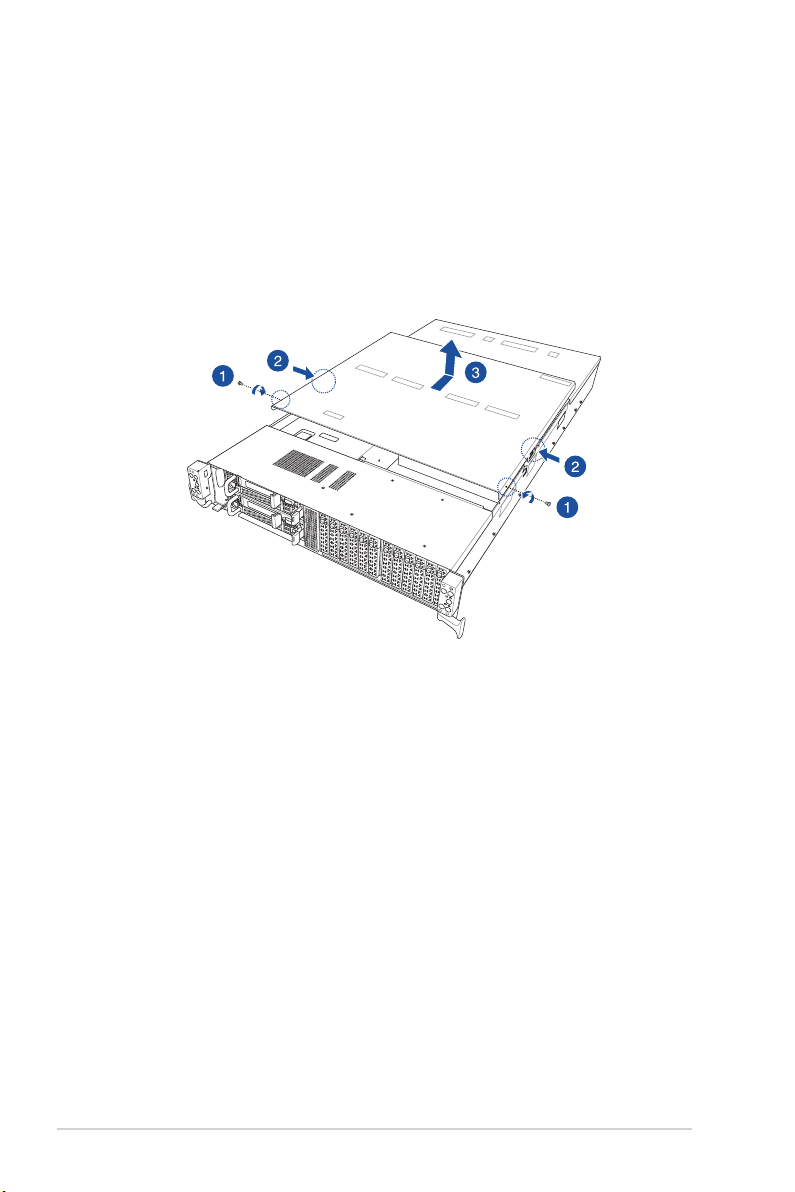
2.1 Chassis cover
To remove the rear cover:
1. Remove the two (2) screws on the rear cover with a Phillips screwdriver.
2. Press the cover latches down on both sides of the rear cover.
3. Lift the rear cover to completely remove it from the chassis.
2-2
Chapter 2: Hardware Information
Page 27
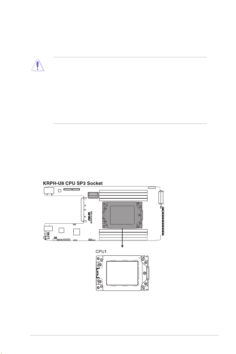
2.2 Central Processing Unit (CPU)
The motherboard comes with a surface mount Socket SP3 designed for the AMD EPYC™
7002 Series.
• Upon purchase of the motherboard, ensure that the PnP cap is on the socket and
the socket contacts are not bent. Contact your retailer immediately if the PnP cap
is missing, or if you see any damage to the PnP cap/socket contacts/motherboard
components. ASUS will shoulder the cost of repair only if the damage is shipment/
transit-related.
• Keep the cap after installing the motherboard. ASUS will process Return Merchandise
Authorization (RMA) requests only if the motherboard comes with the cap on the
Socket SP3.
• The product warranty does not cover damage to the socket contacts resulting from
incorrect CPU installation/removal, or misplacement/loss/incorrect removal of the PnP
cap.
2.2.1 Installing the CPU and heatsink
To install a CPU:
1. Remove the rear cover. For more information, see the section
2. Locate the CPU socket on the motherboard.
Chassis cover
.
ASUS RS620SA-E10-RS12
2-3
Page 28
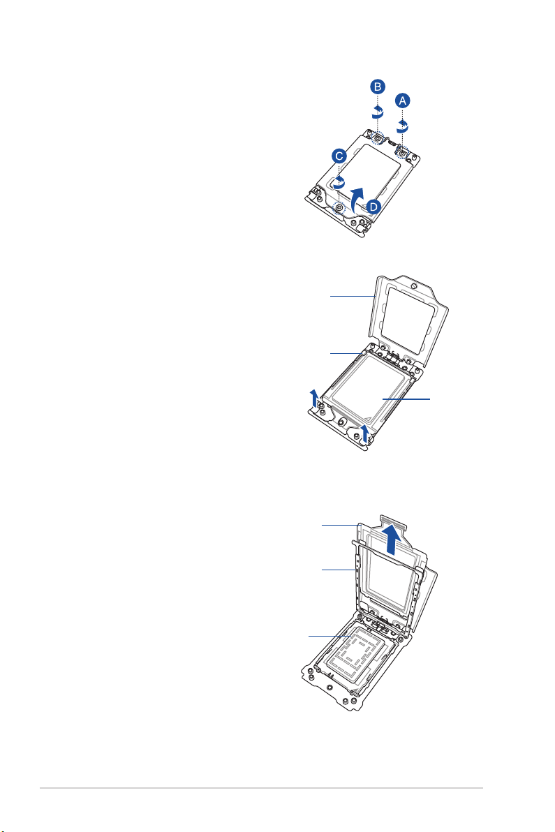
3. Loosen each screw one by one in the
sequence shown on the socket to open
the load plate.
4. Slightly lift open the rail frame.
Load plate
Rail frame
External cap
5. Slide the external cap out of the rail
frame.
2-4
External cap
Rail frame
PnP cap
Chapter 2: Hardware Information
Page 29
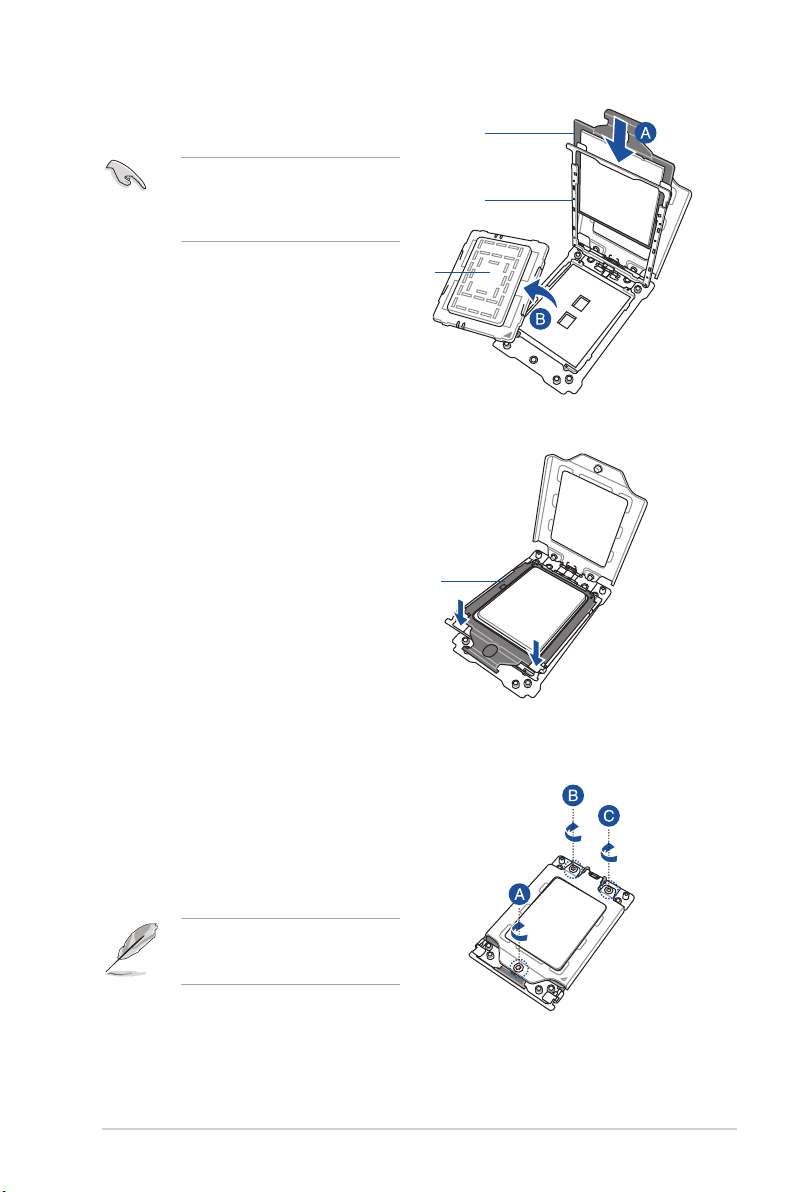
6. Slide the carrier frame with CPU into the
rail frame, then remove the PnP cap.
The carrier frame with CPU fits in only
one correct orientation. DO NOT force
the carrier frame with CPU into the
rail frame.
Carrier frame
with CPU
PnP cap
7. Gently push the rail frame just enough
to let it sit on top of the CPU socket.
Carrier frame
with CPU
Rail frame
8. Close the load plate just enough to let
it sit on top of the CPU, then secure
each screw one by one in the sequence
shown on the socket to completely
secure the load plate.
The load plate screws are T20
models. A torque value of 14 lbf-in is
recommended.
ASUS RS620SA-E10-RS12
2-5
Page 30
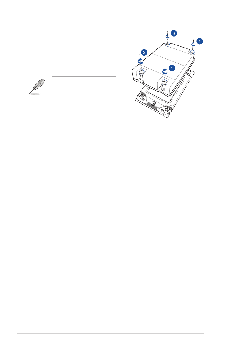
9. Twist each of the four screws with a
Phillips screwdriver just enough to
attach the heatsink to the motherboard.
When the four screws are attached,
tighten them one by one in a diagonal
sequence to completely secure the
heatsink.
The heatsink screws are T20
models. A torque value of 14 lbf-in is
recommended.
2-6
Chapter 2: Hardware Information
Page 31

2.3 System memory
2.3.1 Overview
The motherboard comes with 8 Double Data Rate 4 (DDR4) Dual Inline Memory Modules
(DIMM) sockets.
The figure illustrates the location of the DDR4 DIMM sockets:
ASUS RS620SA-E10-RS12
2-7
Page 32

2.3.2 Memory Configurations
You may install 16GB, 32GB, and 64GB RDIMMs into the DIMM sockets. If you are not sure
on which slots to install the DIMMS, you can use the recommended memory configuration in
this section for reference.
• Refer to ASUS Server AVL for the updated list of compatible DIMMs.
• Always install DIMMs with the same CAS latency. For optimum compatibility, it is
recommended that you obtain memory modules from the same vendor.
Single CPU configuration
A1 B1 C1 D1 E1 F1 G1 H1
1 DIMM
2 DIMMs
4 DIMMs
8 DIMMs
• • • • • • • •
•
• •
• • • •
2-8
Chapter 2: Hardware Information
Page 33

2.3.3 Installing a DIMM on a single clip DIMM socket
Ensure to unplug the power supply before adding or removing DIMMs or other system
components. Failure to do so may cause severe damage to both the motherboard and the
components.
1. Unlock a DIMM socket by pressing the
DIMM notch
retaining clip outward.
2. Align a DIMM on the socket such that
the notch on the DIMM matches the
DIMM slot key on the socket.
DIMM slot key
A DIMM is keyed with a notch so that it fits in only one direction. DO NOT force a DIMM into
a socket in the wrong direction to avoid damaging the DIMM.
Unlocked retaining clip
3. Hold the DIMM by both of its ends
then insert the DIMM vertically into the
socket. Apply force to both ends of the
DIMM simultaneously until the retaining
clip snaps back into place and the
DIMM cannot be pushed in any further
to ensure proper sitting of the DIMM.
Locked Retaining Clip
Always insert the DIMM into the socket vertically to prevent DIMM notch damage.
2.3.4 Removing a DIMM from a single clip DIMM socket
1. Press the retaining clip outward to
unlock the DIMM.
2. Remove the DIMM from the socket.
Support the DIMM lightly with your fingers when pressing the retaining clips. The DIMM
might get damaged when it flips out with extra force.
ASUS RS620SA-E10-RS12
2-9
Page 34

2.4 Storage devices
The system supports twelve (12) 2.5” hot-swap SATA/SAS/NVMe storage devices. The
storage device installed on the storage device tray connects to the motherboard SATA/SAS/
NVMe ports via the SATA/SAS/NVMe backplane.
To install a 2.5” hot-swap SATA/SAS/NVMe storage device:
1. Press the spring lock.
2. Pull the tray lever outwards
to remove the storage device
tray out of the bay.
3. Place the storage device tray
on a flat and stable surface.
4. Remove the two screws and
the metal beam.
5. Prepare the 2.5” storage
device and the bundled set of
screws.
6. Place the 2.5” storage device
into the tray then secure it with
four screws.
7. Push the storage device tray
all the way into the depth of
the bay until the tray lever and
spring lock click and secure
the storage device tray in
place.
8. Repeat steps 1 to 7 to install
the other 2.5” storage devices.
2-10
Chapter 2: Hardware Information
Page 35

2.5 Expansion slot
The barebone server supports one PCIe slot and one OCP Mezzanine slot on board (per
Node).
Riser card
OCP Mezzanine
Riser card
Riser card supports PCIe Gen4 x16.
PCIe slot Operation mode
PCIE1 x16
OCP Mezzanine slot
OCP Mezzanine slot supports PCIe Gen4 x16.
PCIe slot Operation mode
OCP Mezzanine x16
ASUS RS620SA-E10-RS12
2-11
Page 36

2.5.1 Installing an expansion card to riser card
To install an expansion card to the riser card:
1. Remove the two screws that secure
the riser card bracket to the chassis.
2. Remove the riser card bracket.
3. Remove the screw from the metal
cover (A), then remove the metal
cover (B) from the riser card
bracket.
Metal cover
4. Install the PCIE expansion card
into the riser card (A), then
secure the expansion card with
the screw (B).
2-12
Chapter 2: Hardware Information
Page 37

5. Install the riser card bracket and
the PCIE expansion card assembly
into the PCIE_HSDCON1 slot on
the motherboard. Ensure that the
golden connectors of the riser card
is firmly seated in place.
6. Secure the riser card bracket to
the chassis with the two screws
removed in step 1.
ASUS RS620SA-E10-RS12
2-13
Page 38

2.5.2 Configuring an expansion card
After installing the expansion card, configure it by adjusting the software settings.
1. Turn on the system and change the necessary BIOS settings, if any. See Chapter 5 for
information on BIOS setup.
2. Assign an IRQ to the card. Refer to the following tables.
3. Install the software drivers for the expansion card.
Standard Interrupt assignments
IRQ Priority Standard function
0 1 System Timer
1 2 Keyboard Controller
2 - Programmable Interrupt
3* 11 Communications Port (COM2)
4* 12 Communications Port (COM1)
5* 13 --
6 14 Floppy Disk Controller
7* 15 --
8 3 System CMOS/Real Time Clock
9* 4 ACPI Mode when used
10* 5 IRQ Holder for PCI Steering
11* 6 IRQ Holder for PCI Steering
12* 7 PS/2 Compatible Mouse Port
13 8 Numeric Data Processor
14* 9 Primary IDE Channel
15* 10 Secondary IDE Channel
* These IRQs are usually available for ISA or PCI devices.
2-14
Chapter 2: Hardware Information
Page 39

2.5.3 Installing Mezzanine cards
To install a Mezzanine card:
1. Locate the Mezzanine card connector on your motherboard.
2. Remove the screw from the metal
cover (A), then remove the metal
cover (B) from the chassis.
ASUS RS620SA-E10-RS12
2-15
Page 40

3. Prepare the Mezzanine card.
4. Insert the golden connector of
the Mezzanine card into the OCP
connector on the motherboard.
Hot plug not supported, please
complete this step before G3
state.
5. Secure the Mezzanine card with the
mounted screw.
6. (Optional) Secure the Mezzanine
card to the chassis with the bundled
screws.
2-16
Chapter 2: Hardware Information
Page 41

To replace a Mezzanine card:
1. Loosen the mounted screw (A), then
remove the Mezzanine card (B) from
the motherboard.
Hot plug not supported, please
complete this step before G3
state.
2. Prepare the replacement Mezzanine
card.
3. Insert the golden connector of
the replacement Mezzanine card
into the OCP connector on the
motherboard.
4. Secure the replacement Mezzanine
card with the mounted screw.
ASUS RS620SA-E10-RS12
2-17
Page 42

2.5.4 Installing M.2 (NGFF) cards
To install an M.2 (NGFF) card:
1. Remove the screw securing the M.2
riser card to the chassis.
2. Remove the M.2 riser card.
3. Remove the top screw and the
stand screw from the M.2 rise card.
4. Select an appropriate screw hole on
the M.2 riser card for your M.2 card,
then secure the stand screw to the
M.2 riser card.
2-18
Chapter 2: Hardware Information
Page 43

5. Prepare the M.2 card.
6. Align and insert the M.2 card into
the M.2 connector on the M.2 riser
card (A).
Ensure that the golden connector
of the M.2 card is inserted firmly in
place and that the screw hole on the
M.2 card matches the stand screw
on the M.2 riser card.
7. Secure the M.2 card to the M.2 riser
card with the top screw removed in
step 3 (B).
8. Install the M.2 riser card to the M.2
slot on the motherboard (C).
9. Secure the M.2 riser card to the
chassis with the screw removed in
step 1.
ASUS RS620SA-E10-RS12
2-19
Page 44

2.6 Removable/optional components
This section explains how to install optional components into the system and covers the
following components:
1. System fans
2. Redundant power supply module
Ensure that the system is turned off before removing any components.
You may need to remove previously installed component or factory shipped components
when installing optional components.
2.6.1 System fans
To remove the system fans:
1. Locate the fans you want to replace.
2. Remove the cable.
3. Remove the fan.
2-20
Chapter 2: Hardware Information
Page 45

4. Replace the fan with the same model
and size.
5. Connect the cable that you removed in
step 2.
The fan can only be installed in one direction. If the fan cannot be installed, turn it around
and try again.
ASUS RS620SA-E10-RS12
2-21
Page 46

2.6.2 Redundant power supply module
To replace a failed redundant power supply module:
1. Lift up the power supply module lever.
2. Hold the power supply module lever and
press the PSU latch.
3. Pull the power supply module out of the
system chassis.
4. Insert the replacement power supply
module into the chassis then push it
inwards until the latch locks into place.
PSU latch
Module lever
2-22
Chapter 2: Hardware Information
Page 47

2.7 Cable management
You can use the built-in cable sled to manage the cables of the system. Refer to the following
steps on how to manage the cables.
1. From the rear panel, press the latch
(A) and then hold the cable sled to
pull it out of the chassis (B).
Ensure to press the latch and
hold the cable sled at the same
time to prevent damage.
2. Press down the bracket latch (A) to
release the sled bracket.
3. Push the sled bracket out of the cable
sled (B).
4. Pass the cables through the cable
fastener as shown.
5. Turn the cable sled upside down in
the orientation as shown.
6. Pass the cables through the cable
fasteners as shown.
cable sled
latch
sled bracket
cable fastener
ASUS RS620SA-E10-RS12
cable fastener
cable fastener
2-23
Page 48

7. Reinstall the sled bracket that you
removed in step 3.
8. From the rear panel, push the cable
sled into the chassis with the UP
letter facing upwards.
9. Pass the cables through the cable
fasteners before the entire cable sled
is pushed into the chassis.
10. Place all extended cables inside the
cable sled.
11. Push the cable sled into the chassis
until the latch locks in place.
2-24
Chapter 2: Hardware Information
Page 49

12. From the front panel, press down the
latch to release the cable sled.
13. Pull the cable sled out of the chassis.
14. Press down the bracket latch (A) to
release the sled bracket.
15. Push the sled bracket out of the cable
sled (B).
16. Pull out the cables until the length of
the protruding cables is approximately
8 cm.
ASUS RS620SA-E10-RS12
8cm
2-25
Page 50

17. Reinstall the sled bracket that you
removed in step 15.
18. Push the cable sled into the chassis.
The length of the protruding cables is
approximately 16 cm.
19. Connect the cables to the
corresponding ports.
16cm
20. Place all extended and unused cables
inside the cable sled.
2-26
Chapter 2: Hardware Information
Page 51

Chapter 3: Installation Options
Installation Options
This chapter describes how to install the optional components
and devices into the barebone server.
3
Page 52

3.1 Tool-less Friction Rail Kit
The tool less design of the rail kit allows you to easily install the rack rails into the server rack
without the need for additional tools. The kit also comes with a metal stopping bracket that
can be installed to provide additional support and stability to the server.
The tool-less rail kit package includes:
Set of screws
Fixing latches
Rail components (screws included)
Latch screws Rail Washers Rail screws
Tool-less rack rail
3-2
Chapter 3: Installation Options
Page 53

3.2 Installing the tool-less rack rail
To install the tool-less rack rails into the rack:
1. Secure the two fixing latches to the two sides of the server using the set of latch
screws.
The locations of the screw holes vary with different server models. Refer to your server
user manual for details.
2. Select a desired space and place the appropriate rack rail (left and right) on opposite
positions on the rack.
A 1U space consists of three square mounting holes with two thin lips on the top and the
bottom.
ASUS RS620SA-E10-RS12
1U
3-3
Page 54

3. Secure the rail components to the rail using the bundled screws.
4. Press the spring lock (A) then insert the studs into the selected square mounting holes
on the rack post.
5. Press the spring lock on the other end of rail then insert the stud into the mounting hole
on the rack post. Extend the rack rail, if necessary.
6. (Optional) Use the rail screw and rail washer (B) that comes with the kit to secure the
rack rail to the rack post.
7. Perform steps 3 to 5 for the other rack rail.
Ensure that the installed rack rails (left and right) are aligned, secured, and stable in place.
8. Lift the server chassis and insert it into the rack rail.
Ensure that the rack rail cabinet and the rack posts are stable and standing firmly on a level
surface.
3-4
Chapter 3: Installation Options
Page 55

3.3 Rail kit dimensions
43.6mm
43.6mm
900mm
589mm
ASUS RS620SA-E10-RS12
3-5
Page 56

3-6
Chapter 3: Installation Options
Page 57

Chapter 4: Motherboard Information
Motherboard Information
This chapter includes the motherboard layout and brief
descriptions of the jumpers and internal connectors.
4
Page 58

4.1 Motherboard layout
4-2
Chapter 4: Motherboard Information
Page 59

4.1.1 Layout contents
Internal connectors / Sockets / Jumpers / LEDs Page
1. DMLAN setting 4-5
2. BMC Setting 4-5
3. Serial port connector 4-7
4. TPM connector 4-7
5. VGA connector 4-8
6. LANNCSI setting 4-6
7. Clear RTC RAM 4-4
8. Smart Ride Through (SmaRT) setting 4-6
9. Power connector 4-8
10. BMC LED 4-10
11. Standby Power LED 4-10
12. Message LED 4-11
13. Location LED 4-11
14. M.2 slot 4-9
ASUS RS620SA-E10-RS12
4-3
Page 60

4.2 Jumpers
1. Clear RTC RAM
This jumper allows you to clear the Real Time Clock (RTC) RAM in CMOS. You can
clear the CMOS memory of date, time, and system setup parameters by erasing the
CMOS RTC RAM data. The onboard button cell battery powers the RAM data in
CMOS, which include system setup information such as system passwords.
To erase the RTC RAM:
1. Turn OFF the computer and unplug the power cord.
2. Move the jumper cap from pins 1–2 (default) to pins 2–3. Keep the cap on pins 2–3
for about 5–10 seconds, then move the cap back to pins 1–2.
3. Plug the power cord and turn ON the computer.
4. Hold down the <Del> key during the boot process and enter BIOS setup to re-
enter data.
Except when clearing the RTC RAM, never remove the cap on CLRTC jumper default
position. Removing the cap will cause system boot failure!
If the steps above do not help, remove the onboard battery and move the jumper again to
clear the CMOS RTC RAM data. After the CMOS clearance, reinstall the battery.
4-4
Chapter 4: Motherboard Information
Page 61

2. DMLAN setting
This jumper allows you to select the DMLAN setting. Set to pins 2-3 to force the
DMLAN IP to static mode (IP=10.10.10.10, submask=255.255.255.0).
3. BMC Setting
This jumper allows you to enable or disable the ASMB9.
ASUS RS620SA-E10-RS12
4-5
Page 62

4. LANNCSI setting
This jumper allows you to select which LAN NCSI function to use.
5. Smart Ride Through (SmaRT) setting
This jumper allows you to enable or disable the Smart Ride Through (SmaRT) function.
This feature is enabled by default. Set to pins 2-3 to disable it. When enabled, SmaRT
allows uninterrupted operation of the system during an AC loss event.
4-6
Chapter 4: Motherboard Information
Page 63

4.3 Internal connectors
1. Trusted Platform Module connector
This connector supports a Trusted Platform Module (TPM) system, which can securely
store keys, digital certicates, passwords, and data. A TPM system also helps enhance
network security, protects digital identities, and ensures platform integrity.
2. Serial port connector
This connector is for a serial (COM) port. Connect the serial port module cable to this
connector, then install the module to a slot opening at the back of the system chassis.
ASUS RS620SA-E10-RS12
4-7
Page 64

3. VGA connector
This connector supports the VGA High Dynamic-Range interface.
4. Power connector
This power connector connects to the Mid Plane.
4-8
Chapter 4: Motherboard Information
Page 65

5. M.2 slot
This socket allows you to install M.2 SSD devices.
The M.2 SSD module is purchased separately.
ASUS RS620SA-E10-RS12
4-9
Page 66

4.4 Internal LEDs
1. BMC LED
The green heartbeat LED blinks per second to indicate that the ASMB9 is working
normally.
• The heartbeat LED functions only when you enable the ASUS ASMB9.
• Every time after the AC power is replugged, you have to wait for about 30 seconds for
the system to power up.
2. Standby Power LED
The motherboard comes with a standby power LED. The green LED lights up to
indicate that the system is ON, in sleep mode, or in soft-off mode. This is a reminder
that you should shut down the system and unplug the power cable before removing or
plugging in any motherboard component. The illustration below shows the location of
the onboard LED.
4-10
Chapter 4: Motherboard Information
Page 67

3. Message LED
This onboard LED lights up to orange when there is temperature warning or a BMC
event log is generated.
4. Location LED
This onboard LED lights up when the Location button on the server is pressed or when
triggered by a system management software. The Location LED helps visually locate
and quickly identify the server in error on a server rack.
ASUS RS620SA-E10-RS12
4-11
Page 68

4-12
Chapter 4: Motherboard Information
Page 69

Chapter 5: BIOS Setup
BIOS Setup
This chapter tells how to change the system settings through
the BIOS Setup menus. Detailed descriptions of the BIOS
parameters are also provided.
5
Page 70

5.1 Managing and updating your BIOS
The following utilities allow you to manage and update the motherboard Basic Input/Output
System (BIOS) setup:
1. ASUS CrashFree BIOS 3
To recover the BIOS using a bootable USB flash disk drive when the BIOS file fails or
gets corrupted.
2. ASUS EzFlash
Updates the BIOS using a USB flash disk.
3. BUPDATER
Updates the BIOS in DOS mode using a bootable USB flash disk drive.
Refer to the corresponding sections for details on these utilities.
Save a copy of the original motherboard BIOS file to a bootable USB flash disk drive in
case you need to restore the BIOS in the future. Copy the original motherboard BIOS using
the BUPDATER utility.
5.1.1 ASUS CrashFree BIOS 3 utility
The ASUS CrashFree BIOS 3 is an auto recovery tool that allows you to restore the BIOS file
when it fails or gets corrupted during the updating process. You can update a corrupted BIOS
file using a USB flash drive that contains the updated BIOS file.
Prepare a USB flash drive containing the updated motherboard BIOS before using this
utility.
Recovering the BIOS from a USB flash drive
To recover the BIOS from a USB flash drive:
1. Insert the USB flash drive with the original or updated BIOS file to one USB port on the
system.
2. The utility will automatically recover the BIOS. It resets the system when the BIOS
recovery finished.
DO NOT shut down or reset the system while recovering the BIOS! Doing so would cause
system boot failure!
The recovered BIOS may not be the latest BIOS version for this motherboard. Visit the
ASUS website at www.asus.com to download the latest BIOS file.
5-2
Chapter 5: BIOS Setup
Page 71

5.1.2 ASUS EZ Flash Utility
The ASUS EZ Flash Utility feature allows you to update the BIOS without having to use a
DOS-based utility.
Before you start using this utility, download the latest BIOS from the ASUS website at
www.asus.com.
To update the BIOS using EZ Flash Utility:
1. Insert the USB flash disk that contains the latest BIOS file into the USB port.
2. Enter the BIOS setup program. Go to the Tool menu then select Start ASUS EZFlash.
Press <Enter>.
ASUS Tek. EzFlash Utility
Platform : KRPH-U8
Version : 0305
Build date: 07/10/2020
FS0
FS1
[Up/Down/Left/Right]:Switch [Enter]:Choose [q]:Exit
Current Platform
Platform :
Version :
Build date:
New Platform
3. Press the Up/Down arrow keys to find the USB flash disk that contains the latest BIOS,
then press <Enter>.
4. Press the Up/Down arrow keys to find the BIOS file, and then press <Enter> to perform
the BIOS update process. Reboot the system when the update process is done.
• This function can support devices such as a USB flash disk with FAT 32/16 format and
single partition only.
• DO NOT shut down or reset the system while updating the BIOS to prevent system
boot failure!
Ensure to load the BIOS default settings to ensure system compatibility and stability. Press
<F5> and select Yes to load the BIOS default settings.
ASUS RS620SA-E10-RS12
5-3
Page 72

5.1.3 BUPDATER utility
The succeeding BIOS screens are for reference only. The actual BIOS screen displays
may not be the same as shown.
The BUPDATER utility allows you to update the BIOS file in the DOS environment using a
bootable USB flash disk drive with the updated BIOS file.
Updating the BIOS file
To update the BIOS file using the BUPDATER utility:
1. Visit the ASUS website at www.asus.com and download the latest BIOS file for the
motherboard. Save the BIOS file to a bootable USB flash disk drive.
2. Copy the BUPDATER utility (BUPDATER.exe) from the ASUS support website at
www.asus.com/support to the bootable USB flash disk drive you created earlier.
3. Boot the system in DOS mode, then at the prompt, type:
BUPDATER /i[filename].CAP
where [filename] is the latest or the original BIOS file on the bootable USB flash disk
drive, then press <Enter>.
A:\>BUPDATER /i[file name].CAP
5-4
Chapter 5: BIOS Setup
Page 73

4. The utility verifies the file, then starts updating the BIOS file.
ASUS Tek. EzFlash Utility
Platform : KRPH-U8
Version : 0305
Build date: 07/10/2020
Current Platform
Start Programming Flash. DO NOT SHUTDOWN THE SYSTEM!!!
Write
75%
Platform : KRPH-U8
Version : 0317
Build date: 10/02/2020
New Platform
DO NOT shut down or reset the system while updating the BIOS to prevent system boot
failure!
5. The utility returns to the DOS prompt after the BIOS update process is completed.
Reboot the system from the hard disk drive.
The BIOS update is finished! Please restart your system.
C:\>
ASUS RS620SA-E10-RS12
5-5
Page 74

5.2 BIOS setup program
This motherboard supports a programmable firmware chip that you can update using the
provided utility described in section 5.1 Managing and updating your BIOS.
Use the BIOS Setup program when you are installing a motherboard, reconfiguring your
system, or prompted to “Run Setup.” This section explains how to configure your system
using this utility.
Even if you are not prompted to use the Setup program, you can change the configuration of
your computer in the future. For example, you can enable the security password feature or
change the power management settings. This requires you to reconfigure your system using
the BIOS Setup program so that the computer can recognize these changes and record them
in the CMOS RAM of the firmware chip.
The firmware chip on the motherboard stores the Setup utility. When you start up the
computer, the system provides you with the opportunity to run this program. Press <Del>
during the Power-On Self-Test (POST) to enter the Setup utility; otherwise, POST continues
with its test routines.
If you wish to enter Setup after POST, restart the system by pressing <Ctrl>+<Alt>+<Delete>,
or by pressing the reset button on the system chassis. You can also restart by turning the
system off and then back on. Do this last option only if the first two failed.
The Setup program is designed to make it as easy to use as possible. Being a menu-driven
program, it lets you scroll through the various sub-menus and make your selections from the
available options using the navigation keys.
• The default BIOS settings for this motherboard apply for most conditions to ensure
optimum performance. If the system becomes unstable after changing any BIOS
settings, load the default settings to ensure system compatibility and stability. Press
<F5> and select Yes to load the BIOS default settings.
• The BIOS setup screens shown in this section are for reference purposes only, and
may not exactly match what you see on your screen.
• Visit the ASUS website (www.asus.com) to download the latest BIOS file for this
motherboard.
5-6
Chapter 5: BIOS Setup
Page 75

5.2.1 BIOS menu screen
Menu bar Configuration fieldsMenu items
5.2.2 Menu bar
The menu bar on top of the screen has the following main items:
Main For changing the basic system configuration
Advanced For changing the advanced system settings
Chipset For changing the chipset settings
Security For changing the security settings
Boot For changing the system boot configuration
Tool For configuring options for special functions
Save & Exit For selecting the exit options
AMD CBS For configuring AMD CBS settings
Event Logs For changing the event log settings
Server Mgmt For changing the Server Mgmt settings
General help
Navigation keys
To select an item on the menu bar, press the right or left arrow key on the keyboard until the
desired item is highlighted.
ASUS RS620SA-E10-RS12
5-7
Page 76

5.2.3 Menu items
The highlighted item on the menu bar displays the specific items for that menu. For example,
selecting Main shows the Main menu items.
The other items (such as Advanced) on the menu bar have their respective menu items.
5.2.4 Submenu items
A solid triangle before each item on any menu screen means that the item has a submenu.
To display the submenu, select the item then press <Enter>.
5.2.5 Navigation keys
At the bottom right corner of a menu screen are the navigation keys for the BIOS setup
program. Use the navigation keys to select items in the menu and change the settings.
5.2.6 General help
At the top right corner of the menu screen is a brief description of the selected item.
5.2.7 Configuration fields
These fields show the values for the menu items. If an item is user-configurable, you can
change the value of the field opposite the item. You cannot select an item that is not userconfigurable.
A configurable field is enclosed in brackets, and is highlighted when selected. To change the
value of a field, select it and press <Enter> to display a list of options.
5.2.8 Pop-up window
Select a menu item and press <Enter> to display a pop-up window with the configuration
options for that item.
5.2.9 Scroll bar
A scroll bar appears on the right side of a menu screen when there are items that do not fit on
the screen. Press the Up / Down arrow keys or <Page Up> / <Page Down> keys to display
the other items on the screen.
5-8
Chapter 5: BIOS Setup
Page 77

5.3 Main menu
When you enter the BIOS Setup program, the Main menu screen appears. The Main menu
provides you an overview of the basic system information, and allows you to set the system
date, time, and language settings.
5.3.1 System Date [Day xx/xx/xxxx]
Allows you to set the system date.
5.3.2 System Time [xx:xx:xx]
Allows you to set the system time.
ASUS RS620SA-E10-RS12
5-9
Page 78

5.4 Performance Tuning menu
The Performance Tuning menu items allow you to change performance related settings for
different scenarios.
Optimized Performance Setting [Default]
Allows you to select performance settings for different scenarios.
[Default] Default settings.
[By Benchmark] Optimize for different kinds of benchmarks. Select this option, then select a
[By Workload] Optimize for different kinds of workloads. Select this option, then select a
benchmark type from the >> list.
workload type from the >> list.
Configuration options:
[Peak Frequency Optimized] - Applies settings with performance and
power consumption balance. Recommended for users that need higher
performance.
[Latency Optimized] - Applies settings with low latency results.
Recommended for latency-sensitive users.
[Power Efficient Optimized] - Applies settings with power efficiency.
Recommended for general users.
[HPC] - Applies settings with optimized compute capability. Recommend
for traditional HPC applications.
Core Optimizer and Engine Boost appear only when you set Optimized Performance
Setting to [Default] or [By Benchmark].
Core Optimizer [Disabled]
Enable this item to keep the processor operating at the turbo frequency.
Configuration options: [Disabled] [Enabled]
Linux support may vary by version of the OS.
Engine Boost [Disabled]
Enable this item to boost the CPU's frequency.
Configuration options: [Disabled] [Enabled]
5-10
Chapter 5: BIOS Setup
Page 79

Overclocking [Disabled]
Enable this item to increase the CPU’s clock.
Configuration options: [Disabled] [Enabled]
Operate with an ambient temperature of 25oC or lower for optimized performance.
Please note that overclocking might cause component damage or system crashes, which
may reduce the lifespan of the system and the CPU. Use this tool at your own risk.
5.5 Advanced menu
The Advanced menu items allow you to change the settings for the CPU and other system
devices.
Take caution when changing the settings of the Advanced menu items. Incorrect field
values can cause the system to malfunction.
ASUS RS620SA-E10-RS12
5-11
Page 80

5.5.1 Trusted Computing
Configuration
Security Device Support [Enable]
Allows you to enable or disable the BIOS support for security device.
Configuration options: [Disable] [Enable]
5.5.2 PSP Firmware Versions
This page displays the PSP firmware versions.
5.5.3 APM Configuration
Allows you to configure the Advance Power Management (APM) settings.
Restore AC Power Loss [Last State]
When set to [Power Off], the system goes into off state after an AC power loss. When set
to [Power On], the system will reboot after an AC power loss. When set to [Last State], the
system goes into either off or on state, whatever the system state was before the AC power
loss.
Configuration options: [Power Off] [Power On] [Last State]
5-12
Chapter 5: BIOS Setup
Page 81

Power On By PCI-E/PCI [Disabled]
[Disabled] Disables the PCIE devices to generate a wake event.
[Enabled] Enables the PCIE devices to generate a wake event.
Power On By RTC [Disabled]
[Disabled] Disables RTC to generate a wake event.
[Enabled] When set to [Enabled], the items RTC Alarm Date (Days) and
Hour/Minute/Second will become user-configurable with set values.
5.5.4 Onboard LAN Configuration
Onboard I210 LAN Configuration
Intel I210 LAN1
LAN Enable
Allows you to enable or disable the Intel LAN.
Configuration options: [Disabled] [Enabled]
The following item appears only when LAN Enable is set to [Enabled].
ROM Type [PXE]
Allows you to select the Intel LAN ROM type.
Configuration options: [Disabled] [PXE] [iSCSI]
ASUS RS620SA-E10-RS12
5-13
Page 82

5.5.5 Serial Port Console Redirection
COM1/COM2
Console Redirection [Disabled]
Allows you to enable or disable the console redirection feature.
Configuration options: [Disabled] [Enabled]
The following item appears only when Console Redirection is set to [Enabled].
Console Redirection Settings
These items become configurable only when you enable the Console Redirection
item. The settings specify how the host computer and the remote computer (which the
user is using) will exchange data. Both computers should have the same or compatible
settings.
Terminal Type [ANSI]
Allows you to set the terminal type.
[VT100] ASCII char set.
[VT100+] Extends VT100 to support color, function keys, etc.
[VT-UTF8] Uses UTF8 encoding to map Unicode chars onto 1 or more bytes.
[ANSI] Extended ASCII char set.
Bits per second [115200]
Selects serial port transmission speed. The speed must be matched on the other side.
Long or noisy lines may require lower speeds.
Configuration options: [9600] [19200] [38400] [57600] [115200]
Data Bits [8]
Configuration options: [7] [8]
5-14
Chapter 5: BIOS Setup
Page 83

Parity [None]
A parity bit can be sent with the data bits to detect some transmission errors. [Mark]
and [Space] parity do not allow for error detection.
[None] None
[Even] parity bit is 0 if the num of 1’s in the data bits is even
[Odd] parity bit is 0 if num of 1’s in the data bits is odd
[Mark] parity bit is always 1
[Space] parity bit is always 0
Stop Bits [1]
Stop bits indicate the end of a serial data packet. (A start bit indicates the beginning.)
The standard setting is 1 stop bit. Communication with slow devices may require more
than 1 stop bit.
Configuration options: [1] [2]
Flow Control [None]
Flow control can prevent data loss from buffer overflow. When sending data, if the
receiving buffers are full, a “stop” signal can be sent to stop the data flow. Once the
buffers are empty, a “start” signal can be sent to re-start the flow. Hardware flow
control uses two wires to send start/stop signals.
Configuration options: [None] [Hardware RTS/CTS]
VT–UTF8 Combo Key Support [Enabled]
This allows you to enable the VT–UTF8 Combination Key Support for ANSI/VT100
terminals.
Configuration options: [Disabled] [Enabled]
Recorder Mode [Disabled]
With this mode enabled only text will be sent. This is to capture Terminal data.
Configuration options: [Disabled] [Enabled]
Resolution 100x31 [Enabled]
This allows you enable or disable extended terminal solution.
Configuration options: [Disabled] [Enabled]
Putty Keypad [VT100]
This allows you to select the FunctionKey and Keypad on Putty.
Configuration options: [VT100] [LINUX] [XTERMR6] [SCO] [ESCN] [VT400]
ASUS RS620SA-E10-RS12
5-15
Page 84

Legacy Console Redirection Settings
Redirection COM Port [COM1]
Allows you to select a COM port to display redirection of Legacy OS and Legacy
OPROM Messages.
Configuration options: [COM1] [COM2]
Resolution [80x24]
This allows you to set the number of rows and columns supported on the Legacy OS.
Configuration options: [80x24] [80x25]
Redirection After POST [Always Enable]
This setting allows you to specify if Bootloader is selected than Legacy console
redirection.
Configuration options: [Always Enable] [Bootloader]
Out-of-Band Management/
Windows Emergency Management Services (EMS)
Console Redirection [Disabled]
Allows you to enable or disable the console redirection feature.
Configuration options: [Disabled] [Enabled]
The following item appears only when Console Redirection is set to [Enabled].
Console Redirection Settings
Out-of-Band Mgmt Port [COM1]
Microsoft Windows Emergency Management Services (EMS) allow for remote
management of a Windows Server OS through a serial port.
Configuration options: [COM1] [COM2]
Terminal Type [VT–UTF8]
Microsoft Windows Emergency Management Services (EMS) allow for remote
management of a Windows Server OS through a serial port.
Configuration options: [VT100] [VT100+] [VT–UTF8] [ANSI]
Bits per second [115200]
Microsoft Windows Emergency Management Services (EMS) allow for remote
management of a Windows Server OS through a serial port.
Configuration options: [9600] [19200] [57600] [115200]
Flow Control [None]
Microsoft Windows Emergency Management Services (EMS) allow for remote
management of a Windows Server OS through a serial port.
Configuration options: [None] [Hardware RTS/CTS] [Software Xon/Xoff]
5-16
Chapter 5: BIOS Setup
Page 85

5.5.6 CPU Configuration
This page displays the CPU node information.
SVM Mode [Enable]
This item allows you enable or disable CPU Virtualization.
Configuration options: [Disabled] [Enable]
SMEE [Enable]
This item allows you to enable or disable control secure memory encryption.
Configuration options: [Disabled] [Enable]
Node 0 Information
This item allows you to view memory information related to Node 0.
ASUS RS620SA-E10-RS12
5-17
Page 86

5.5.7 PCI Subsystem Settings
Allows you to configure PCI, PCI-X, and PCI Express Settings.
VGA Palette Snoop [Disabled]
This option enables or disables VGA Palette Registers Snooping.
Configuration options: [Disabled] [Enabled]
Above 4G Decoding [Enabled]
Allows you to enable or disable 64-bit capable devices to be decoded in above 4G address
space. It only works if the system supports 64-bit PCI decoding.
Configuration options: [Disabled] [Enabled]
SR-IOV Support [Enabled]
This option enables or disables SIngle Root IO Virtualization Support if the system has SRIOV capable PCIe devices.
Configuration options: [Disabled] [Enabled]
BME DMA Mitigation [Disabled]
This allows you to enable or disable re-enabling Bus Master Attribute disabled during Pci
enumeration for PCI Bridges after SMM locked.
Configuration options: [Disabled] [Enabled]
PCIE OPROM Slot Options
PCIE1 Slot OPROM [Enabled]
This option allows you to enable or disable the OPROM of the PCIe slot.
Configuration options: [Disabled] [Enabled]
MEZZ1 Slot OPROM [Enabled]
This option allows you to enable or disable the OPROM of the Mezzanine slot.
Configuration options: [Disabled] [Enabled]
5-18
Chapter 5: BIOS Setup
Page 87

5.5.8 USB Configuration
Legacy USB Support [Enabled]
Allows you to enable or disable Legacy USB device support.
Configuration options: [Enabled] [Disabled] [Auto]
XHCI Hand-off [Enabled]
Allows you to enable or disable workaround for OSes without XHCI hand-off support. The
XHCI ownership change should be claimed by XHCI driver.
Configuration options: [Enabled] [Disabled]
USB Mass Storage Driver Support [Enabled]
Allows you to enable or disable the USB Mass Storage driver support.
Configuration options: [Disabled] [Enabled]
Port 60/64 Emulation [Enabled]
Allows you to enable or disable I/O port 60h/64h emulation support. This should be enabled
for the complete keyboard legacy support for non-USB aware OSes.
Configuration options: [Disabled] [Enabled]
USB hardware delays and time-outs
USB transfer time-out [20 sec]
Allows you to select time-out value for Control, Bulk, and Interrupt transfers.
Configuration options: [1 sec] [5 sec] [10 sec] [20 sec]
Device reset time-out [20 sec]
Allows you to select time-out value for USB mass storage device Start Unit command.
Configuration options: [10 sec] [20 sec] [30 sec] [40 sec]
ASUS RS620SA-E10-RS12
5-19
Page 88

Device power-up delay [Auto]
Allows you to select maximum time the device will take before it properly reports itself to the
Host Controller.
Configuration options: [Auto] [Manual]
Mass Storage Devices
Allows you to select the mass storage device emulation type for devices connected.
Configuration options: [Auto] [Floppy] [Forced FDD] [Hard Disk] [CD-ROM]
5.5.9 Network Stack Configuration
Network Stack [Disabled]
Enables or disables the network stack feature.
Configuration options: [Disable] [Enable]
The following item appears only when Network stack is set to [Enabled].
Ipv4 PXE Support [Disabled]
Enables or disables the Ipv4 PXE Boot Support. If disabled, Ipv4 PXE boot option will
not be created.
Configuration options: [Disabled] [Enabled]
Ipv4 HTTP Support [Disabled]
Enables or disables the Ipv4 HTTP Boot Support. If disabled, Ipv4 HTTP boot option
will not be created.
Configuration options: [Disabled] [Enabled]
Ipv6 PXE Support [Disabled]
Enables or disables the Ipv6 PXE Boot Support. If disabled, Ipv6 PXE boot option will
not be created.
Configuration options: [Disabled] [Enabled]
Ipv6 HTTP Support [Disabled]
Enables or disables the Ipv6 HTTP Boot Support. If disabled, Ipv6 HTTP boot option
will not be created.
Configuration options: [Disabled] [Enabled]
PXE boot wait time [0]
Set the wait time to press ESC key to abort the PXE boot. Use the <+> or <-> to adjust
the value. The values range from 0 to 5.
Media detect count [1]
Set the number of times presence of media will be checked. Use the <+> or <-> to
adjust the value. The values range from 1 to 50.
5-20
Chapter 5: BIOS Setup
Page 89

5.5.10 CSM Configuration
CSM Support [Disabled]
This option allows you to enable or disable CSM Support.
Configuration options: [Disabled] [Enabled]
The following item appears only when CSM Support is set to [Enabled].
GateA20 Active [Upon Request]
This allows you to set the GA20 option.
Configuration options: [Upon Request] [Always]
Option ROM Messages [Force BIOS]
This allows you to set the display mode for option ROM.
Configuration options: [Force BIOS] [Keep Current]
INT19 Trap Response [Immediate]
[Immediate] Execute the trap right away.
[Postponed] Execute the trap during legacy boot.
HDD Connection Order [Adjust]
This option allows you to select the HDD Connection Order. Some OS require HDD
handles to be adjusted.
Configuration options: [Adjust] [Keep]
Boot Option filter [UEFI and Legacy]
This option allows you to control the Legacy/UEFI ROMs priority.
Configuration options: [UEFI and Legacy] [Legacy only] [UEFI only]
ASUS RS620SA-E10-RS12
5-21
Page 90

Network / Storage / Video [Legacy]
This option allows you to control the execution of UEFI and Legacy PXE / Storage /
Video OpROM.
Configuration options: [Do not launch] [UEFI] [Legacy]
Other PCI devices [Legacy]
This item determines the OpROM execution policy for devices other than Network,
Storage, or Video.
Configuration options: [UEFI] [Legacy]
5.5.11 SATA Configuration
This page will display the SATA controller and drive information.
5.5.12 NVMe Configuration
This page will display the NVMe controller and drive information.
5-22
Chapter 5: BIOS Setup
Page 91

5.5.13 AMD Mem Configuration Status
The items in this menu display the memory configuration (initialized by ABL) status.
5.5.14 iSCSI Configuration
Allows you to configure the iSCSI parameters.
ASUS RS620SA-E10-RS12
5-23
Page 92

5.6 Chipset menu
The Chipset menu items allow you to change the Chipset settings.
PCIe Link Training Type [1 Step]
This item allows you to select PCIe Link Training in 1 or 2 steps.
Configuration options: [1 Step] [2 Step]
PCIe Compliance Mode [Off]
This item allows you to turn the PCIe Compliance Mode on or off.
North Bridge
Memory Configuration
Socket 0 Information
This item displays the memory information on Socket 0.
5-24
Chapter 5: BIOS Setup
Page 93

5.7 Security menu
This menu allows a new password to be created or a current password to be changed. The
menu also enables or disables the Secure Boot state and lets the user configure the System
Mode state.
Administrator Password
To set an administrator password:
1. Select the Administrator Password item and press <Enter>.
2. From the Create New Password box, key in a password, then press <Enter>.
3. Confirm the password when prompted.
To change an administrator password:
1. Select the Administrator Password item and press <Enter>.
2. From the Enter Current Password box, key in the current password, then press
<Enter>.
3. From the Create New Password box, key in a new password, then press <Enter>.
4. Confirm the password when prompted.
To clear the administrator password, follow the same steps as in changing an administrator
password, but press <Enter> when prompted to create/confirm the password.
ASUS RS620SA-E10-RS12
5-25
Page 94

User Password
To set a user password:
1. Select the User Password item and press <Enter>.
2. From the Create New Password box, key in a password, then press <Enter>.
3. Confirm the password when prompted.
To change a user password:
1. Select the User Password item and press <Enter>.
2. From the Enter Current Password box, key in the current password, then press
<Enter>.
3. From the Create New Password box, key in a new password, then press <Enter>.
4. Confirm the password when prompted.
To clear a user password:
1. Select the Clear User Password item and press <Enter>.
2. Select Yes from the Warning message window then press <Enter>.
Secure Boot
This item allows you to customize the Secure Boot settings.
Secure Boot [Disabled]
Secure Boot can be enabled if the system is running in User mode with enrolled platform Key
(EPK) or if the CSM function is disabled.
Configuration options: [Disabled] [Enabled]
Secure Boot Mode [Custom]
Allows you to set the Secure Boot selector.
Configuration options: [Standard] [Custom]
Restore Factory Keys
This option will force the system to User Mode, and install factory default Secure Boot key
databases.
Reset to Setup Mode
This option will delete all Secure Boot key databases from NVRAM.
5-26
Chapter 5: BIOS Setup
Page 95

Key Management
This item only appears when the item Secure Boot Mode is set to [Custom]. The Key
Management item allows you to modify Secure Boot variables and set Key Management
page.
Factory Key Provision [Enabled]
Allows you to provision factory default Secure Boot keys when the system is in Setup
Mode.
Configuration options: [Disabled] [Enabled]
Restore Factory keys
This item will install all Factory Default keys.
Reset to Setup Mode
This item appears only when you load the default Secure Boot keys. This item allows
you to clear all default Secure Boot keys.
Export Secure Boot Variables
This item will ask you if you want to save all secure boot variables. Select Yes if you
want to save all secure boot variables, otherwise select No.
Enroll Efi Image
This item will allow the image to run in Secure Boot mode.
Configuration options: [Set New] [Append]
ASUS RS620SA-E10-RS12
5-27
Page 96

Device Guard Ready
Remove ‘UEFI CA’ from DB
Remove Microsoft UEFI CA from Secure Boot DB.
Restore DB defaults
Restore DB variable to factory defaults.
Platform Key (PK)
Configuration options: [Details] [Export] [Update] [Delete]
Key Exchange Keys / Authorized Signatures / Forbidden Signatures
Configuration options: [Details] [Export] [Update] [Append] [Delete]
Authorized TimeStamps / OsRecovery Signatures
Configuration options: [Update] [Append]
5-28
Chapter 5: BIOS Setup
Page 97

5.8 Boot menu
The Boot menu items allow you to change the system boot options.
Setup Prompt Timeout [1]
Allows you to set the number of seconds that the firmware waits before initiating the original
default boot selection. 65535(OxFFFF) means indefinite waiting. Use the <+> or <-> to adjust
the value.
Bootup NumLock State [On]
Allows you to select the power-on state for the NumLock.
Configuration options: [On] [Off]
Quiet Boot [Disabled]
Allows you to enable or disable Quiet Boot option.
Configuration options: [Disabled] [Enabled]
Boot Option Priorities
These items specify the boot device priority sequence from the available devices. The
number of device items that appears on the screen depends on the number of devices
installed in the system.
• To select the boot device during system startup, press <F8> when ASUS Logo
appears.
• To access Windows OS in Safe Mode, please press <F8> after POST.
ASUS RS620SA-E10-RS12
5-29
Page 98

5.9 Tool menu
The Tool menu items allow you to configure options for special functions. Select an item then
press <Enter> to display the submenu.
IPMI HWM
Allows you to run the IPMI hardware monitor.
Start ASUS EzFlash
Allows you to run ASUS EzFlash BIOS ROM Utility when you press <Enter>. Refer to the
ASUS EzFlash Utility section for details.
5-30
Chapter 5: BIOS Setup
Page 99

5.10 Save & Exit menu
The Exit menu items allow you to save or discard your changes to the BIOS items.
Pressing <Esc> does not immediately exit this menu. Select one of the options from this
menu or <F10> from the legend bar to exit.
Discard Changes and Exit
Exit system setup without saving any changes.
Save Changes and Reset
Exit system setup after saving the changes.
Save Changes
Save changes done so far to any of the setup options.
Discard Changes
Discard changes done so far to any of the setup options.
Restore Defaults
Restore/load default values for all the setup options.
Boot Override
These items displays the available devices. The device items that appears on the screen
depends on the number of devices installed in the system. Click an item to start booting from
the selected device.
ASUS RS620SA-E10-RS12
5-31
Page 100

5.11 AMD CBS menu
The items in this menu shows the AMD Common BIOS Specifications.
5.11.1 CPU Common Options
Prefetcher settings
L1 Stream HW Prefetcher [Auto]
This item allows you to enable or disable L1 Stream HW Prefetcher.
Configuration options: [Disable] [Enable] [Auto]
L2 Stream HW Prefetcher [Auto]
This item allows you to enable or disable L2 Stream HW Prefetcher.
Configuration options: [Disable] [Enable] [Auto]
Core Watchdog
Core Watchdog Timer Enable [Auto]
This item allows you to enable or disable CPU Watchdog Timer.
Configuration options: [Disabled] [Enabled] [Auto]
5-32
Chapter 5: BIOS Setup
 Loading...