


ASUS RS100-E7-PI2, E6489 User Manual
1U Rackmount Server
RS100-E7/PI2
User Guide

ii
Copyright © 2011 ASUSTeK COMPUTER INC. All Rights Reserved.
No part of this manual, including the products and software described in it, may be reproduced, transmitted,
transcribed, stored in a retrieval system, or translated into any language in any form or by any means,
except documentation kept by the purchaser for backup purposes, without the express written permission
of ASUSTeK COMPUTER INC. (“ASUS”).
ASUS provides this manual “as is” without warranty of any kind, either express or implied, including but not
limited to the implied warranties or conditions of merchantability or tness for a particular purpose. In no
event shall ASUS, its directors, ofcers, employees, or agents be liable for any indirect, special, incidental,
or consequential damages (including damages for loss of prots, loss of business, loss of use or data,
interruption of business and the like), even if ASUS has been advised of the possibility of such damages
arising from any defect or error in this manual or product.
Specications and information contained in this manual ae furnished for informational use only, and are
subject to change at any time without notice, and should not be construed as a commitment by ASUS.
ASUS assumes no responsibility or liability for any errors or inaccuracies that may appear in this manual,
including the products and software described in it.
Product warranty or service will not be extended if: (1) the product is repaired, modied or altered, unless
such repair, modication of alteration is authorized in writing by ASUS; or (2) the serial number of the
product is defaced or missing.
Products and corporate names appearing in this manual may or may not be registered trademarks or
copyrights of their respective companies, and are used only for identication or explanation and to the
owners’ benet, without intent to infringe.
E6489
First Edition
March 2011

iii
Contents
Contents ...................................................................................................... iii
Notices ........................................................................................................ vii
Safety information .................................................................................... viii
About this guide ......................................................................................... ix
Chapter 1: Product introduction
1.1 System package contents ........................................................... 1-2
1.2 Serial number label ...................................................................... 1-2
1.3 Systemspecications ................................................................. 1-3
1.4 Front panel features ..................................................................... 1-5
1.5 Rear panel features ...................................................................... 1-5
1.6 Internal features ........................................................................... 1-6
1.7 LED information ........................................................................... 1-7
1.7.1 Front panel LEDs ............................................................ 1-7
1.7.2 LAN (RJ-45) LEDs .......................................................... 1-7
Chapter 2: Hardware setup
2.1 Chassis cover ............................................................................... 2-2
2.1.1 Removing the chassis cover ........................................... 2-2
2.1.2 Reinstalling the chassis cover ......................................... 2-3
2.2 Central Processing Unit (CPU) ................................................... 2-5
2.2.1 Installing the CPU ........................................................... 2-5
2.2.2 Installing the CPU heatsink and airduct .......................... 2-8
2.3 System memory ......................................................................... 2-10
2.3.1 Overview ....................................................................... 2-10
2.3.2 Memory Congurations ................................................. 2-10
2.3.3 Installing a DIMM ...........................................................2-11
2.3.4 Removing a DIMM .........................................................2-11
2.4 Hard disk drives ......................................................................... 2-12
2.4.1 Installing a hard disk drive to the HDD tray 1 ................ 2-12
2.4.2 Installing a hard disk drive to the HDD tray 2 ................ 2-13
2.5 Expansion card .......................................................................... 2-15
2.5.1 Installing an expansion card ......................................... 2-15
2.5.2 Conguring an expansion card ..................................... 2-17
2.6 Cable connections ..................................................................... 2-18
2.7 Removable/optional components ............................................. 2-19
2.7.1 Chassis fans ................................................................. 2-19

iv
Contents
2.7.2 Optical disk drive (ODD) ............................................... 2-20
2.7.3 Installing ASMB5 series management board (optional) 2-22
Chapter 3: Rackmount installation
3.1 Rackmount rail kit items .............................................................. 3-2
3.2 Attaching the rails to the rack ..................................................... 3-2
Chapter 4: Motherboard Info
4.1 Motherboard layout ...................................................................... 4-2
4.2 Jumpers ........................................................................................ 4-4
4.3 Internal connectors ...................................................................... 4-9
Chapter 5: BIOS setup
5.1 Managing and updating your BIOS ............................................ 5-2
5.1.1 ASUS CrashFree BIOS 3 utility ...................................... 5-2
5.1.2 ASUS EZ Flash Utility ..................................................... 5-3
5.1.3 BUPDATER utility............................................................ 5-4
5.2 BIOS setup program .................................................................... 5-6
5.2.1 BIOS menu screen .......................................................... 5-7
5.2.2 Menu bar ......................................................................... 5-7
5.2.3 Menu items ..................................................................... 5-8
5.2.4 Submenu items ............................................................... 5-8
5.2.5 Navigation keys ............................................................... 5-8
5.2.6 General help ................................................................... 5-8
5.2.7 Conguration elds ......................................................... 5-8
5.2.8 Pop-up window ............................................................... 5-8
5.2.9 Scroll bar ......................................................................... 5-8
5.3 Main menu .................................................................................... 5-9
5.3.1 System Date [Day xx/xx/xxxx] ......................................... 5-9
5.3.2 System Time [xx:xx:xx] ................................................... 5-9
5.3.3 Security ........................................................................... 5-9
5.4 Event Logs menu ....................................................................... 5-11
5.5 Advanced menu ......................................................................... 5-13
5.5.1 ACPI Settings ................................................................ 5-13
5.5.2 Trusted Computing ........................................................ 5-14
5.5.3 WHEA Conguration ..................................................... 5-14
5.5.4 CPU Conguration ........................................................ 5-15

v
Contents
5.5.5 North Bridge .................................................................. 5-17
5.5.6 South Bridge ................................................................. 5-17
5.5.7 SATA Conguration ....................................................... 5-18
5.5.8 Intel TXT(LT) Conguration ........................................... 5-19
5.5.9 USB Conguration ........................................................ 5-19
5.5.10 Onboard Devices Conguration .................................... 5-20
5.5.11 APM .............................................................................. 5-21
5.5.12 Serial Port Console Redirection .................................... 5-22
5.6 Monitor menu ............................................................................. 5-24
5.7 Boot menu .................................................................................. 5-25
5.8 Tool menu ................................................................................... 5-27
5.9 Exit menu .................................................................................... 5-27
Chapter6: RAIDconguration
6.1 Setting up RAID ............................................................................ 6-2
6.1.1 RAID denitions .............................................................. 6-2
6.1.2 Installing hard disk drives ................................................ 6-3
6.1.3 Setting the RAID item in BIOS ........................................ 6-3
6.1.4 RAID conguration utilities .............................................. 6-3
6.2 Intel® Rapid Storage Technology Option ROM Utility ............... 6-4
6.2.1 Creating a RAID set ........................................................ 6-5
6.2.2 Creating a Recovery set ................................................. 6-6
6.2.3 Deleting a RAID set ........................................................ 6-8
6.2.4 Resetting disks to Non-RAID .......................................... 6-9
6.2.5 Recovery Volume Options ............................................ 6-10
6.2.6 Exiting the Intel® Rapid Storage Technology utility .........6-11
6.2.7 Rebuilding the RAID ......................................................6-11
6.2.8 Setting the Boot array in the BIOS Setup Utility ............ 6-13
Chapter 7: Driver installation
7.1 RAID driver installation ............................................................... 7-2
7.1.1 Creating a RAID driver disk ............................................ 7-2
7.1.2 Installing the RAID controller driver ................................ 7-5

vi
7.2 Intel® chipset device software installation ............................... 7-14
7.3 LAN driver installation ............................................................... 7-16
7.4 VGA driver installation............................................................... 7-19
7.5 Management applications and utilities installation ................ 7-22
7.5.1 Running the support DVD ............................................. 7-22
7.5.2 Drivers menu ................................................................. 7-22
7.5.3 Utilities menu ................................................................ 7-23
7.5.4 Make disk menu ............................................................ 7-23
7.5.5 Contact information ....................................................... 7-23
vii
Notices
Federal Communications Commission Statement
This device complies with Part 15 of the FCC Rules. Operation is subject to the
following two conditions:
•
This device may not cause harmful interference, and
•
This device must accept any interference received including interference that
may cause undesired operation.
This equipment has been tested and found to comply with the limits for a Class
A digital device, pursuant to Part 15 of the FCC Rules. These limits are designed
to provide reasonable protection against harmful interference in a residential
installation. This equipment generates, uses and can radiate radio frequency
energy and, if not installed and used in accordance with manufacturer’s instructions,
may cause harmful interference to radio communications. However, there is
no guarantee that interference will not occur in a particular installation. If this
equipment does cause harmful interference to radio or television reception, which
can be determined by turning the equipment off and on, the user is encouraged to
try to correct the interference by one or more of the following measures:
•
Reorient or relocate the receiving antenna.
•
Increase the separation between the equipment and receiver.
•
Connect the equipment to an outlet on a circuit different from that to which the
receiver is connected.
•
Consult the dealer or an experienced radio/TV technician for help.
Canadian Department of Communications Statement
This digital apparatus does not exceed the Class B limits for radio noise emissions
from digital apparatus set out in the Radio Interference Regulations of the
Canadian Department of Communications.
This Class B digital apparatus complies with Canadian ICES-003.
WARNING! The use of shielded cables for connection of the monitor to the
graphics card is required to assure compliance with FCC regulations. Changes
or modications to this unit not expressly approved by the party responsible for
compliance could void the user’s authority to operate this equipment.
REACH
Complying with the REACH (Registration, Evaluation, Authorization, and Restriction
of Chemicals) regulatory framework, we publish the chemical substances in our
products at ASUS REACH website at http://green.asus.com/english/REACH.htm.
viii
Safety information
Electrical Safety
• Before installing or removing signal cables, ensure that the power cables for
the system unit and all attached devices are unplugged.
• To prevent electrical shock hazard, disconnect the power cable from the
electrical outlet before relocating the system.
• When adding or removing any additional devices to or from the system, contact
a qualied service technician or your dealer. Ensure that the power cables for
the devices are unplugged before the signal cables are connected. If possible,
disconnect all power cables from the existing system before you service.
• If the power supply is broken, do not try to x it by yourself. Contact a qualied
service technician or your dealer.
Operation Safety
• Servicing of this product or units is to be performed by trained service
personnel only.
• Before operating the server, carefully read all the manuals included with the
server package.
• Before using the server, make sure all cables are correctly connected and the
power cables are not damaged. If any damage is detected, contact your dealer
as soon as possible.
• To avoid short circuits, keep paper clips, screws, and staples away from
connectors, slots, sockets and circuitry.
• Avoid dust, humidity, and temperature extremes. Place the server on a stable
surface.
This product is equipped with a three-wire power cable and plug for the user’s
safety. Use the power cable with a properly grounded electrical outlet to avoid
electrical shock.
Lithium-Ion Battery Warning
CAUTION! Danger of explosion if battery is incorrectly replaced. Replace
only with the same or equivalent type recommended by the manufacturer.
Dispose of used batteries according to the manufacturer’s instructions.
CD-ROM Drive Safety Warning
CLASS 1 LASER PRODUCT
Heavy System
CAUTION! This server system is heavy. Ask for assistance when moving or
carrying the system.
ix
About this guide
Audience
This user guide is intended for system integrators, and experienced users with at
least basic knowledge of conguring a server.
Contents
This guide contains the following parts:
1. Chapter 1: Product Introduction
This chapter describes the general features of the server, including sections
on front panel and rear panel specications.
2. Chapter 2: Hardware setup
This chapter lists the hardware setup procedures that you have to perform
when installing or removing system components.
3. Chapter 3: Rackmount installation
This chapter describes how to install the rackmount rail kit to the barebone
server
4. Chapter 4: Motherboard information
This chapter includes the motherboard layout and brief descriptions of the
jumpers and internal connectors.
5. Chapter 5: BIOS information
This chapter tells how to change system settings through the BIOS Setup
menus and describes the BIOS parameters.
6. Chapter 6: Driver installation
This chapter provides instructions for installing the necessary drivers for
different system components.
DO NOT throw the motherboard in municipal waste. This product has been
designed to enable proper reuse of parts and recycling. This symbol of the
crossed out wheeled bin indicates that the product (electrical and electronic
equipment) should not be placed in municipal waste. Check local regulations for
disposal of electronic products.
DO NOT throw the mercury-containing button cell battery in municipal waste.
This symbol of the crossed out wheeled bin indicates that the battery should not
be placed in municipal waste.
x
References
Refer to the following sources for additional information, and for product and
software updates.
1. ASUS Server Web-based Management (ASWM) user guide
This manual tells how to set up and use the proprietary ASUS server
management utility.
2. ASUS websites
The ASUS websites worldwide provide updated information for all ASUS
hardware and software products. Refer to the ASUS contact information.
Conventions
To make sure that you perform certain tasks properly, take note of the following
symbols used throughout this manual.
Typography
Bold text
Indicates a menu or an item to select.
Italics
Used to emphasize a word or a phrase.
<Key> Keys enclosed in the less-than and greater-than
sign means that you must press the enclosed key.
Example: <Enter> means that you must press
the Enter or Return key.
<Key1+Key2+Key3> If you must press two or more keys simultaneously,
the key names are linked with a plus sign (+).
Example: <Ctrl+Alt+D>
Command
Means that you must type the command exactly
as shown, then supply the required item or value
enclosed in brackets.
Example: At the DOS prompt, type the
command line:
format A:/S
DANGER/WARNING: Information to prevent injury to yourself when
trying to complete a task.
NOTE: Tips and additional information to help you complete a task.
IMPORTANT: Instructions that you MUST follow to complete a task.
CAUTION: Information to prevent damage to the components when
trying to complete a task.
This chapter describes the general
features of the server, including
sections on front panel and rear panel
specications.
Chapter 1
Product introduction
Chapter 1: Product introduction1-2
*ASUS System Web-based Management
If any of the above items is damaged or missing, contact your retailer.
1.1 System package contents
Check your system package for the following items.
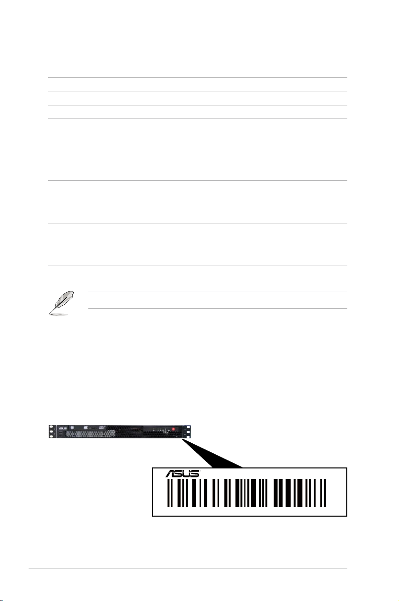
1.2 Serial number label
Before requesting support from the ASUS Technical Support team, you must
take note of the product’s serial number containing 14 characters such as
xxS0xxxxxxxxxx shown as the gure below. With the correct serial number of the
product, ASUS Technical Support team members can then offer a quicker and
satisfying solution to your problems.
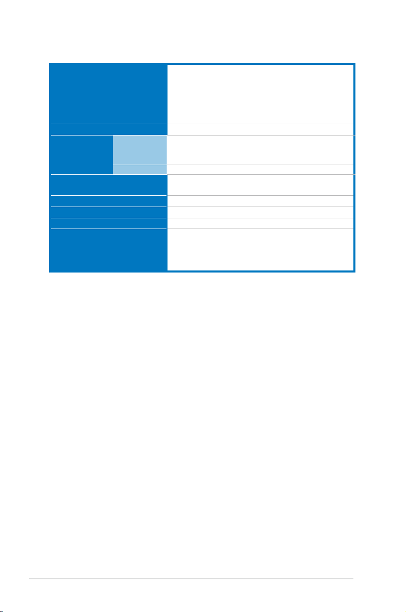
Model Name RS100-E7/PI2
Chassis ASUS R09 1U Rackmount Chassis
Motherboard ASUS P8B-M Server Board
Component 1 x 220W Single Power Supply
2 x SATA Cables
1 x PCI Express x16 Riser Card (PCIE16-R11)
1 x Front I/O Board (FPB-R9)
1 x USB Board (USB-R9)
2 x System Fans (40mm x 28mm)
Accessories 1 x RS100-E7/PI2 User’s Guide
1 x RS100-E7/PI2 Support CD
1 x Bag of Screws
1 x AC Power Cable
Optional
Items
CPU Heatsink
ASUS ASMB5-iKVM Remote management card
Slim-type Optical Device
Ball Bearing Rail Kit
xxS0xxxxxxxxxx
RS100-E7/PI2
ASUS RS100-E7/PI2 1-3
1.3 Systemspecications
The ASUS RS100-E7/PI2 is a 1U barebone server system featuring the ASUS
P8B-M server board. The server supports Intel® LGA1155 Lynneld / Clarkdale
processors, plus other latest technologies through the chipsets onboard.
Model Name RS100-E7/PI2
Processor / System Bus
1 x Socket LGA1155
Intel® Xeon® E3-1200 Processor Family
Intel® CoreTM i3-2100 Processor Family
Core Logic
Intel® C204 Chipset
ASUS Features
Smart Fan
√
ASWM2.0
√
Memory
Total Slots
4 (2 Channels)
Capacity
Maximum up to 32GB
Do not support R-DIMM and non ECC U-DIMM
Memory Type
DDR3 1333 / 1066 Unbuffered DIMM with ECC
Memory Size
1 GB, 2GB, 4GB, 8GB
Expansion
Slots
Total PCI/PCI-X/
PCI-E Slots
1
Slot Type
1 x PCI-E 2.0 x16 slot (x16 link) (Full-Height/HL)
Storage
2 x SATA3 6Gb/s
Intel® C204 (for Windows only)
- Supports software RAID 0 & 1
HDD Bays
I = internal
A or S = hotswappable
2 x Internal 3.5” SATA2 HDD Bays
Networking LAN
2 x Intel® 82574L + 1 x Mgmt LAN
Graphic VGA
Aspeed® AST2050 16MB
Auxiliary Storage FDD / CD / DVD
1 x Slim-type Optical Device Bay
(Options: No ODD / DVD-ROM / DVD-RW)
Onboard I/O
1 x External Serial Port
3 x RJ-45 ports (1 for ASMB5-iKVM)
4 x USB 2.0 ports (Front x 2, Rear x 2)
1 x VGA port
1 x PS/2 keyboard port
1 x PS/2 mouse port
(continued on the next page)
Chapter 1: Product introduction1-4
*Specicationsaresubjecttochangewithoutnotice.
OS Support
Windows® Server 2008 R2
Windows® Server 2008 Enterprise 32/64-bit
Windows® Server 2003 R2 Enterprise 32/64-bit
RedHat® Enterprise Linux AS5.5/6.0 32/64-bit
SuSE® Linux Enterprise Server 10 SP3/11 32/64-bit
(Subject to change without any notice)
Anti-virus Software
Optional anti-virus CD Pack
Management
Solution
Out of Band
Remote
Hardware
Optional ASMB5-iKVM for KVM-over-IP support
Software
ASUS ASWM Enterprise
®
Net Weight Kg (CPU, DRAM &
HDD not inclu ded)
6.5 Kg
Dimension (DD x WW x HH)
380mm x 429.6mm x 43.2mm
Power Supply
220W Single Power Supply
Power Rating
Input: 100-240Vac, 4-2A, 50-60Hz, Class I
Environment
Operation temperature: 10°C–35°C / Non operation
temperature: -40°C–70°C
Non operation humidity: 20%–90%
( Non-condensing)
ASUS RS100-E7/PI2 1-5
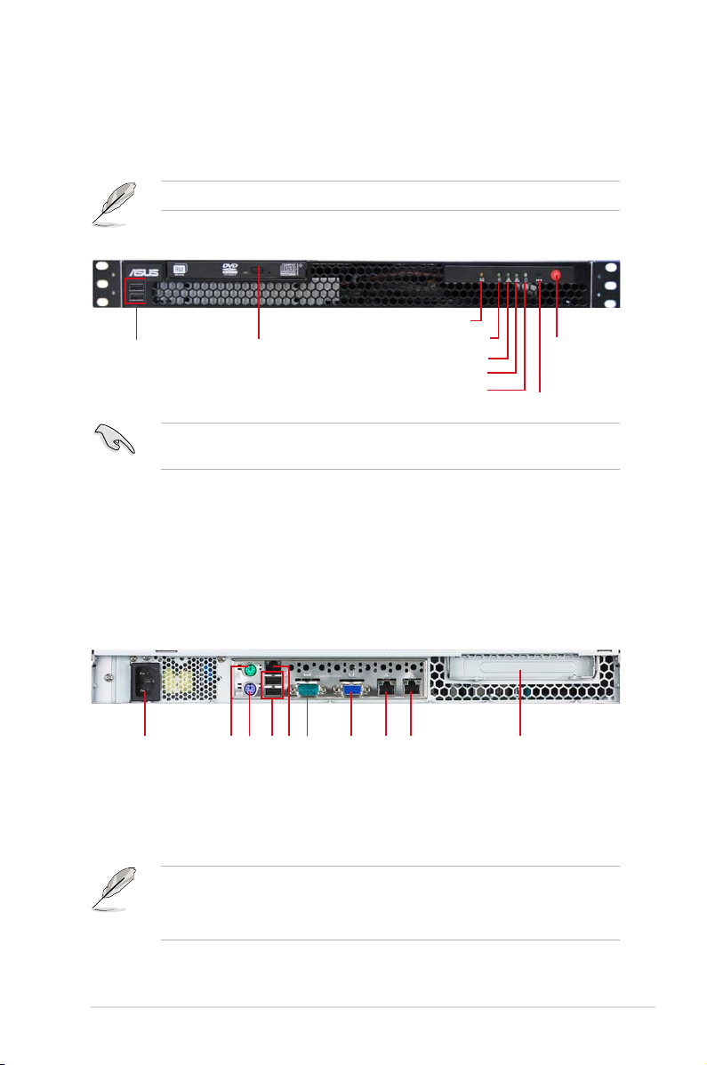
1.4 Front panel features
The barebone server displays a simple yet stylish front panel with easily accessible
features. The power and reset buttons, LED indicators, optical drive, and twp USB
ports are located on the front panel.
Refer to section 1.7.1 Front panel LEDs for the LED descriptions.
Turn off the system power and detach the power supply before removing or
replacing any system component.
1.5 Rear panel features
The rear panel includes the expansion slot and system power socket. The I/O
shield with openings for the rear panel connectors on the motherboard are also
placed in the rear panel.
AC power socket
USB 2.0 ports
PS/2 mouse port
PS/2 keyboard port
Serial port
VGA port
LAN port 1
LAN port 2
Expansion slot
LAN port 3*
Optical drive
USB 2.0 ports
HDD Access LED
LAN2 LED
LAN1 LED
Power LED
Reset button
Power button
• The ports for the PS/2 keyboard, PS/2 mouse, USB, VGA, and Gigabit LAN
do not appear on the rear panel if motherboard is not present.
• *The port is for ASUS ASMB5-iKVM controller card only.
Message LED
Chapter 1: Product introduction1-6
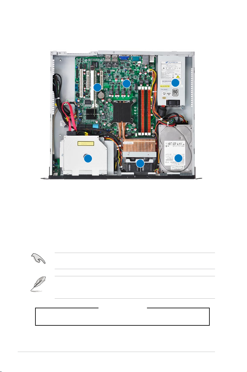
1.6 Internal features
The barebone server includes the basic components as shown.
The barebone server does not include a oppy disk drive. Connect a USB oppy
disk drive to any of the USB ports on the front or rear panel if you need to use a
oppy disk.
Turn off the system power and detach the power supply before removing or
replacing any system component.
*WARNING
HAZARDOUS MOVING PARTS
KEEP FINGERS AND OTHER BODY PARTS AWAY
1. PCI Express x16 Riser Card (at x16 link)
2. System Fan (x2) (9GV0412P3J051)
3. ASUS P8B-M Server Board
4. Power Supply
5. HDD Tray 2 (hidden) and Slim-type Optical
Drive (optional)
6. HDD Tray 1
6
1
2
3
4
5
ASUS RS100-E7/PI2 1-7
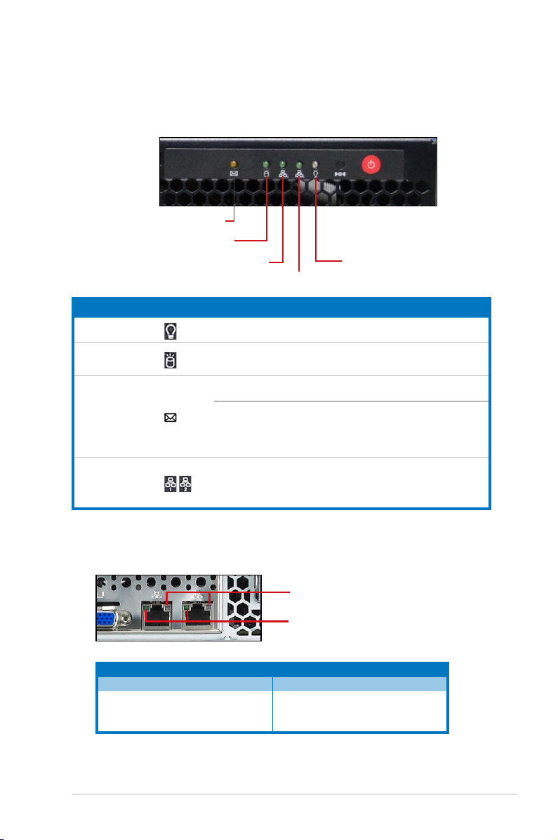
1.7 LED information
1.7.1 Front panel LEDs
LED Icon Display status Description
Power LED ON System power ON
HDD Access LED
OFF
Blinking
No activity
Read/write data into the HDD
Message LED
OFF
System is normal; no incoming event
ON
1. Without ASMB5-iKVM installed: CPU
over-heated
2. With ASMB5-iKVM installed: a
hardware monitor event is indicated
LAN LEDs
OFF
Blinking
ON
No LAN connection
LAN is transmitting or receiving data
LAN connection is present
HDD Access LED
LAN2 LED
LAN1 LED
Power LED
1.7.2 LAN (RJ-45) LEDs
ACT/LINK LED SPEED LED
Status Description Status Description
OFF No link OFF 10 Mbps connection
GREEN Linked ORANGE 100 Mbps connection
BLINKING Data activity GREEN 1 Gbps connection
SPEED LED
ACT/LINK LED
Message LED

Chapter 1: Product introduction1-8
This chapter lists the hardware setup
procedures that you have to perform
when installing or removing system
components.
Chapter 2
Hardware setup
Chapter 2: Hardware setup2-2
2.1 Chassis cover
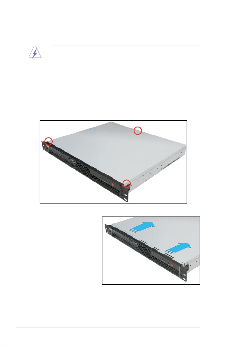
2.1.1 Removing the chassis cover
• Ensure that you unplug the power cord before removing the chassis cover.
• Take extra care when removing the chassis cover. Keep your ngers from
components inside the chassis that can cause injury, such as the CPU fan,
rear fan, and other sharp-edged parts.
• The images of the barebone server shown in this section are for reference
purposes only and may not exactly match the model you purchase.
To remove the chassis cover:
1. Use a Phillips screwdriver to remove the three screws on the chassis cover.
2. Firmly hold the cover and
slide it toward the rear
panel for about half an inch
until it is disengaged from
the chassis.
3. Lift the cover from the chassis.
2-3ASUS RS100-E7/PI2
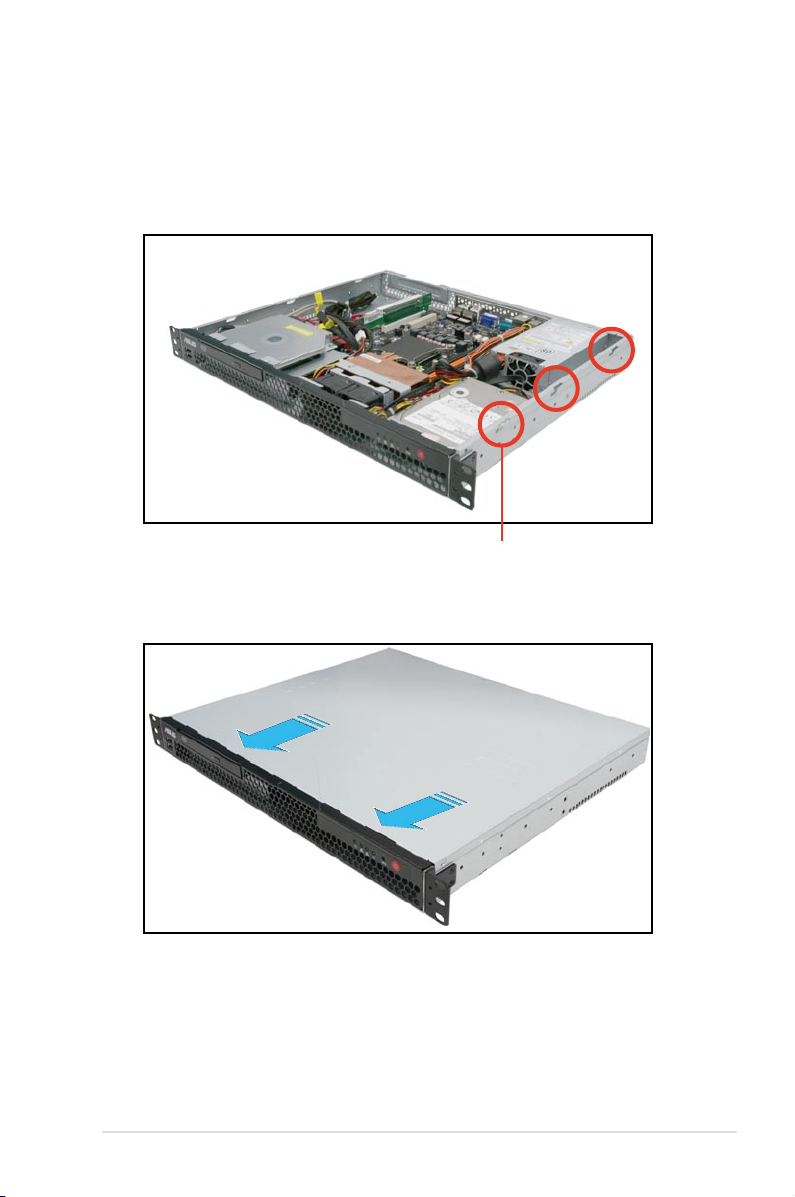
2.1.2 Reinstalling the chassis cover
To reinstall the chassis cover:
1. Position the cover on top of the chassis with the hooks aligned to the side
tabs of the chassis.
2. Slide the cover toward the front until it snaps in place.
Side tabs
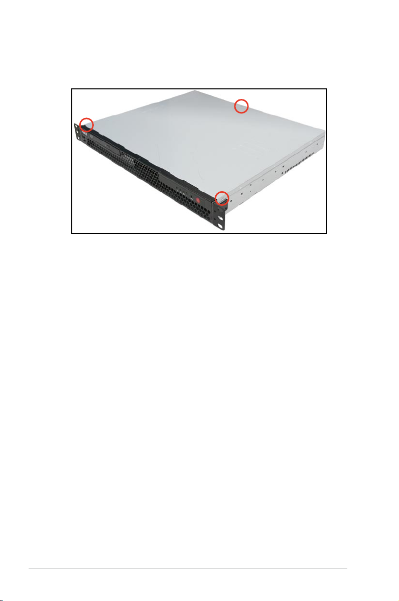
Chapter 2: Hardware setup2-4
3. Secure the cover with three screws.
2-5ASUS RS100-E7/PI2
2.2.1 Installing the CPU
To install a CPU:
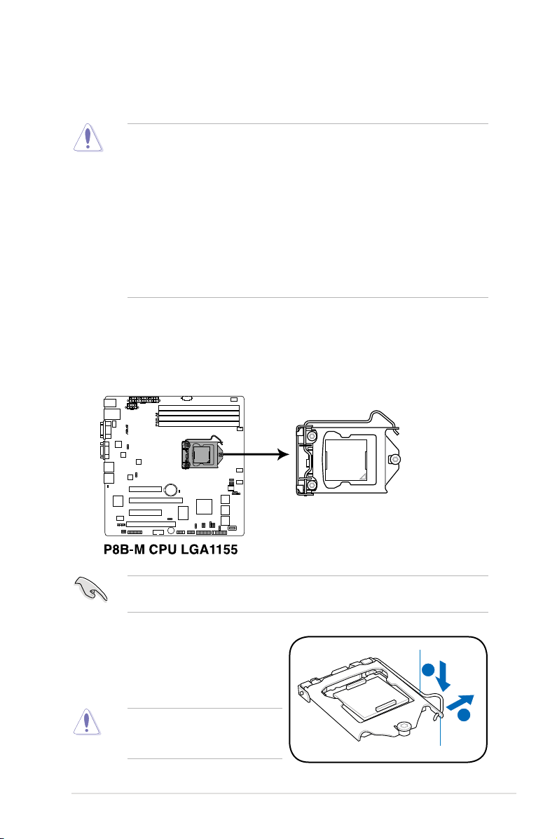
1. Locate the CPU socket on the motherboard.
Before installing the CPU, ensure that the socket box is facing toward you and
the load lever is on your left.
2.2 Central Processing Unit (CPU)
The motherboard comes with a surface mount LGA1155 socket designed for the
Intel® Xeon E3-1200/Core™ i3-2100 processor.
• Upon purchase of the motherboard, ensure that the PnP cap is on
the socket and the socket contacts are not bent. Contact your retailer
immediately if the PnP cap is missing, or if you see any damage to the PnP
cap/socket contacts/motherboard components. ASUS will shoulder the cost
of repair only if the damage is shipment/transit-related.
• Keep the cap after installing the motherboard. ASUS will process Return
Merchandise Authorization (RMA) requests only if the motherboard comes
with the cap on the LGA1155 socket.
• The product warranty does not cover damage to the socket contacts
resulting from incorrect CPU installation/removal, or misplacement/loss/
incorrect removal of the PnP cap.
To prevent damage to the socket
pins, do not remove the PnP cap
unless you are installing a CPU.
A
B
Load lever
Retention tab
2. Press the load lever with your
thumb (A), and then move it to the
right (B) until it is released from the
retention tab.
Chapter 2: Hardware setup2-6
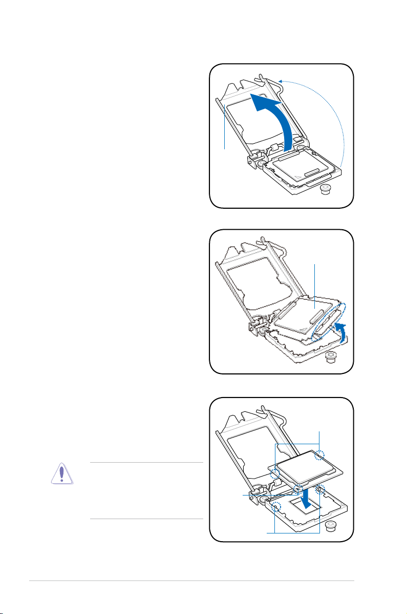
The CPU ts in only one correct
orientation. DO NOT force the
CPU into the socket to prevent
bending the connectors on the
socket and damaging the CPU!
Gold
triangle
mark
Alignment keys
CPU notches
5. Position the CPU over the socket,
ensuring that the gold triangle is on
the bottom-left corner of the socket,
and then t the socket alignment
keys into the CPU notches.
4. Remove the PnP cap from the CPU
socket.
PnP cap
3. Lift the load lever in the direction
of the arrow until the load plate is
completely lifted.
Load plate
2-7ASUS RS100-E7/PI2
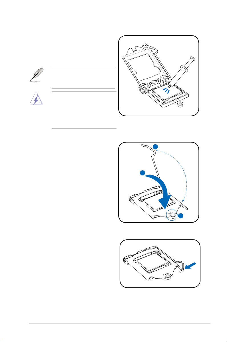
7. Close the load plate (A), and then
push down the load lever (B),
ensuring that the front edge of the
load plate slides under the retention
lock (C).
C
B
A
8. Insert the load lever under the
retention tab.
Some heatsinks come with preapplied thermal paste. If so, skip
this step.
The Thermal Interface Material is
toxic and inedible. DO NOT eat it.
If it gets into your eyes or touches
your skin, wash it off immediately,
and seek professional medical
help.
6. Apply some Thermal Interface
Material to the exposed area of
the CPU that the heatsink will be
in contact with, ensuring that it is
spread in an even thin layer.
Chapter 2: Hardware setup2-8
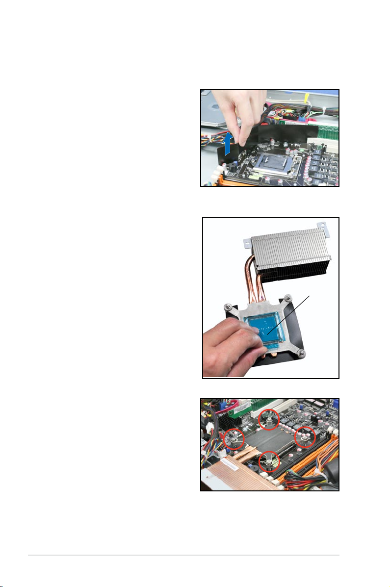
2.2.2 Installing the CPU heatsink and airduct
To install the CPU heatsink:
1. Lift one side of the mylar and set it
aside for installing the CPU heatsink.
Protection sticker
3. Place the heatsink on top of the
installed CPU, ensuring that the
four fasteners match the holes on
the motherboard.
2. Remove the protection sticker on
the back of the CPU heatsink.
2-9ASUS RS100-E7/PI2
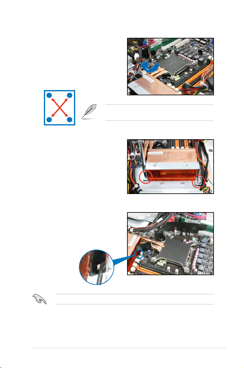
Tighten the four heatsink screws in a diagonal
sequence.
A
B
B
A
4. Twist each of the four screws with
a Philips (cross) screwdriver just
enough to attach the heatsink to
the motherboard. When the four
screws are attached, tighten them
one by one to completely secure
the heatsink.
5. Secure the heat pipe and air duct
to the server with two screws.
6. Set the mylar back to its original
place. When the mylar is properly
installed, the hook as shown below
should attach the motherboard edge.
Ensure that the mylar does not interfere any motherboard headers or capacitors.
Chapter 2: Hardware setup2-10
2.3 System memory
2.3.1 Overview
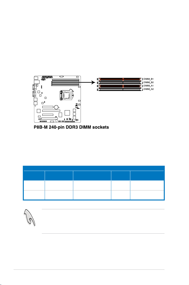
The motherboard comes with four Double Data Rate 3 (DDR3) Dual Inline Memory
Modules (DIMM) sockets.
A DDR3 module has the same physical dimensions as a DDR2 DIMM but is
notched differently to prevent installation on a DDR2 DIMM socket. DDR3 modules
are developed for better performance with less power consumption.
The gure illustrates the location of the DDR3 DIMM sockets:
2.3.2 MemoryCongurations
You may install 1GB, 2GB, 4GB and 8GB Unbuffered with ECC DDR3 DIMMs into
the DIMM sockets using the memory congurations in this section.
UDIMM
DIMM Slot
Per Channel
DIMM Populated
per Channel
DIMM Type Speed Rank per DIMM
2 1 Unbuffered DDR3 ECC 1066/1333
Single Rank,
Dual Rank
2 2 Unbuffered DDR3 ECC 1066/1333
Single Rank,
Dual Rank
• Start installing the DIMMs from slot A1 and B1 (orange).
• Always install DIMMs with the same CAS latency. For optimum
compatibility, it is recommended that you obtain memory modules from the
same vendor.
2-11ASUS RS100-E7/PI2
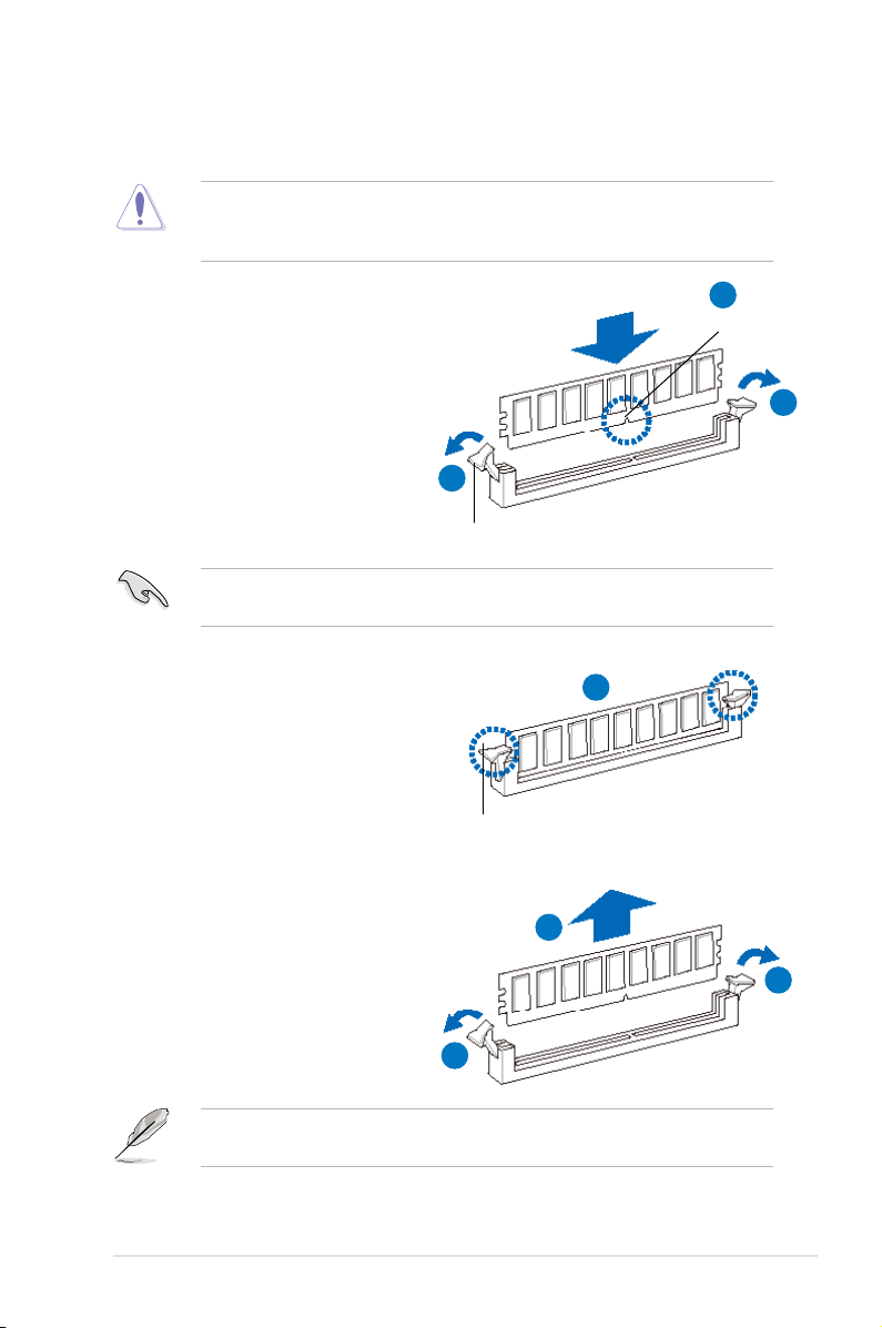
2.3.3 Installing a DIMM
2.3.4 Removing a DIMM
Follow these steps to remove a DIMM.
1. Simultaneously press the
retaining clips outward to unlock
the DIMM.
2. Remove the DIMM from the socket.
1
1
2
3. Firmly insert the DIMM into the
socket until the retaining clips snap
back in place and the DIMM is
properly seated.
Ensure to unplug the power supply before adding or removing DIMMs or other
system components. Failure to do so may cause severe damage to both the
motherboard and the components.
A DIMM is keyed with a notch so that it ts in only one direction. DO NOT force
a DIMM into a socket to avoid damaging the DIMM.
Unlocked retaining clip
1
DIMM notch
1. Unlock a DIMM socket by pressing
the retaining clips outward.
2. Align a DIMM on the socket
such that the notch on the DIMM
matches the break on the socket.
Locked Retaining Clip
2
1
Support the DIMM lightly with your ngers when pressing the retaining clips.
The DIMM might get damaged when it ips out with extra force.
3
Chapter 2: Hardware setup2-12
2.4 Hard disk drives
You can install up to two (2) Serial ATA hard disk drives to the system. Follow the
succeeding instructions to install each of the drives.
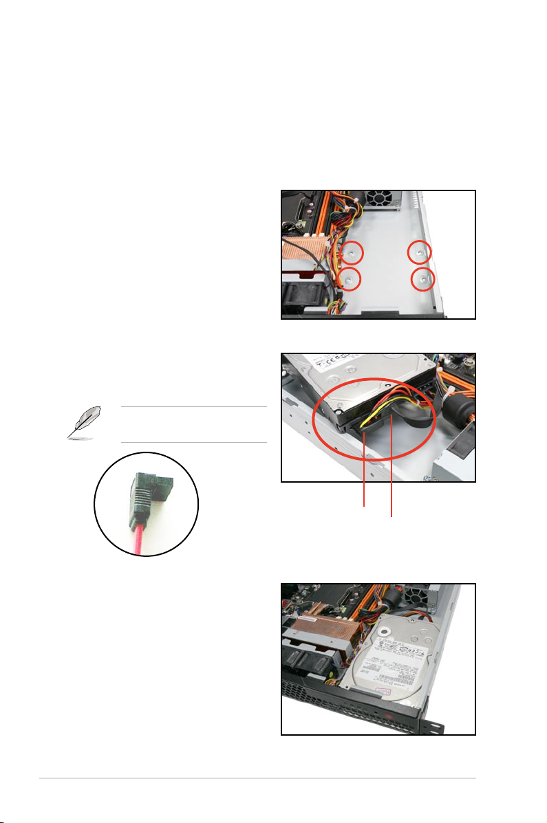
2.4.1 Installing a hard disk drive to the HDD tray 1
To install a hard disk drive to the HDD tray 1:
1. Locate the HDD tray 1 beside the
power supply unit. Notice the four
standard screw holes.
2. Connect the SATA signal cable and
a power plug from the power supply
to the hard disk drive.
L-type SATA
connector
3. Place the hard disk drive into the
HDD tray 1 matching the four screw
holes with the holes on the disk
drive.
Power plug
SATA signal cable
Use the L-type SATA connector
to connect to the hard disk drive.
 Loading...