

Page 1

P5QD Turbo
Motherboard
Page 2

E4875
First Edition (V1)
July 2009
Copyright © 2009 ASUSTeK COMPUTER INC. All Rights Reserved.
No part of this manual, including the products and software described in it, may be reproduced,
transmitted, transcribed, stored in a retrieval system, or translated into any language in any form or by any
means, except documentation kept by the purchaser for backup purposes, without the express written
permission of ASUSTeK COMPUTER INC. (“ASUS”).
Product warranty or service will not be extended if: (1) the product is repaired, modied or altered, unless
such repair, modication of alteration is authorized in writing by ASUS; or (2) the serial number of the
product is defaced or missing.
ASUS PROVIDES THIS MANUAL “AS IS” WITHOUT WARRANTY OF ANY KIND, EITHER EXPRESS
OR IMPLIED, INCLUDING BUT NOT LIMITED TO THE IMPLIED WARRANTIES OR CONDITIONS OF
MERCHANTABILITY OR FITNESS FOR A PARTICULAR PURPOSE. IN NO EVENT SHALL ASUS, ITS
DIRECTORS, OFFICERS, EMPLOYEES OR AGENTS BE LIABLE FOR ANY INDIRECT, SPECIAL,
INCIDENTAL, OR CONSEQUENTIAL DAMAGES (INCLUDING DAMAGES FOR LOSS OF PROFITS,
LOSS OF BUSINESS, LOSS OF USE OR DATA, INTERRUPTION OF BUSINESS AND THE LIKE),
EVEN IF ASUS HAS BEEN ADVISED OF THE POSSIBILITY OF SUCH DAMAGES ARISING FROM ANY
DEFECT OR ERROR IN THIS MANUAL OR PRODUCT.
SPECIFICATIONS AND INFORMATION CONTAINED IN THIS MANUAL ARE FURNISHED FOR
INFORMATIONAL USE ONLY, AND ARE SUBJECT TO CHANGE AT ANY TIME WITHOUT NOTICE,
AND SHOULD NOT BE CONSTRUED AS A COMMITMENT BY ASUS. ASUS ASSUMES NO
RESPONSIBILITY OR LIABILITY FOR ANY ERRORS OR INACCURACIES THAT MAY APPEAR IN THIS
MANUAL, INCLUDING THE PRODUCTS AND SOFTWARE DESCRIBED IN IT.
Products and corporate names appearing in this manual may or may not be registered trademarks or
copyrights of their respective companies, and are used only for identication or explanation and to the
owners’ benet, without intent to infringe.
ii
Page 3

Contents
Contents ...................................................................................................................... iii
Notices ......................................................................................................................
Safety information .................................................................................................... viii
About this guide ......................................................................................................... ix
P5QD Turbo specications summary ....................................................................... xi
Chapter 1: Product introduction
1.1 Welcome! ....................................................................................................1-1
1.2 Package contents
1.3 Special features
1.3.1 Product highlights
1.3.2 ASUS special features ................................................................
1.3.3 ASUS exclusive overclocking features
Chapter 2: Hardware information
2.1 Before you proceed ...................................................................................2-1
2.2 Motherboard overview ...............................................................................
2.2.1 Motherboard layout .....................................................................
2.2.2 Layout contents ...........................................................................
2.2.3 Placement direction
2.2.4 Screw holes
2.3 Central Processing Unit (CPU) .................................................................
2.3.1 Installing the CPU .......................................................................
2.3.2 Installing the CPU heatsink and fan ............................................
2.3.3 Uninstalling the CPU heatsink and fan
2.4 System memory .......................................................................................
2.4.1 Overview ...................................................................................
2.4.2 Memory congurations ..............................................................
2.4.3 Installing a DIMM ......................................................................
2.4.4 Removing a DIMM ....................................................................
2.5 Expansion slots
2.5.1 Installing an expansion card
2.5.2 Conguring an expansion card .................................................
2.5.3 Interrupt assignments
2.5.4 PCI slots ....................................................................................
2.5.5 PCI Express x1 slots .................................................................
2.5.6 PCI Express 2.0 x16 slot (blue)
2.6 Jumpers ....................................................................................................
2.7 Connectors ...............................................................................................
2.7.1 Rear panel connectors ..............................................................
....................................................................................... 1-1
.......................................................................................... 1-2
........................................................................ 1-2
1-2
........................................ 1-4
2-2
2-2
2-3
..................................................................... 2-4
................................................................................. 2-4
2-5
2-5
2-8
........................................ 2-9
2-10
2-10
2-11
2-17
2-17
........................................................................................ 2-18
...................................................... 2-18
2-18
................................................................ 2-19
2-20
2-20
................................................. 2-20
2-21
2-24
2-24
vii
iii
Page 4

Contents
2.7.2 Audio I/O connections ............................................................... 2-25
2.7.3 Internal connectors
2.8 Starting up for the rst time ....................................................................
2.9 Turning off the computer .........................................................................
Chapter 3: BIOS setup
3.1 Knowing BIOS ............................................................................................3-1
3.2 Updating BIOS ............................................................................................
3.2.1 ASUS Update utility
3.2.2 ASUS EZ Flash 2 utility ...............................................................
3.2.3 ASUS CrashFree BIOS 3 utility
3.3 BIOS setup program ..................................................................................
3.3.1 BIOS menu screen ......................................................................
3.3.2 Menu bar .....................................................................................
3.3.3 Navigation keys ...........................................................................
3.3.4 Menu items
3.3.5 Submenu items ...........................................................................
3.3.6 Conguration elds .....................................................................
3.3.7 Pop-up window
3.3.8 Scroll bar .....................................................................................
3.3.9 General help
3.4 Main menu ..................................................................................................
3.4.1 SATA 1-5; SATA_E1 ....................................................................
3.4.2 Storage Conguration ...............................................................
3.4.3 AHCI Conguration ...................................................................
3.4.4 System Information ...................................................................
3.5 Ai Tweaker menu ......................................................................................
3.5.1 Ai Overclock Tuner [Auto] .........................................................
3.5.2 CPU Ratio Setting [Auto]
3.5.3 FSB Frequency [XXX] ...............................................................
3.5.4 PCIE Frequency [XXX]
3.5.5 FSB Strap to North Bridge [Auto] ..............................................
3.5.6 DRAM Frequency [Auto] ...........................................................
3.5.7 DRAM Timing Control [Auto] .....................................................
3.5.8 DRAM Static Read Control [Auto] .............................................
3.5.9 DRAM Read Training [Auto] ......................................................
3.5.10 MEM. OC Charger [Auto] ..........................................................
3.5.11 Ai Clock Twister [Auto] ..............................................................
3.5.12 Ai Transaction Booster [Auto]
.................................................................... 2-28
..................................................................... 3-2
................................................... 3-5
.................................................................................. 3-7
............................................................................ 3-7
................................................................................ 3-7
........................................................... 3-13
.............................................................. 3-13
.................................................... 3-15
2-39
2-39
3-1
3-4
3-6
3-6
3-6
3-7
3-7
3-7
3-7
3-8
3-8
3-10
3-11
3-11
3-12
3-12
3-13
3-13
3-13
3-13
3-15
3-15
3-15
3-15
iv
Page 5

Contents
3.5.13 CPU Voltage [Auto] ................................................................... 3-16
3.5.14 CPU GTL Reference [Auto] .......................................................
3.5.15 CPU PLL Voltage [Auto] ............................................................
3.5.16 FSB Termination Voltage [Auto] ................................................
3.5.17 DRAM Voltage [Auto] ................................................................
3.5.18 NB Voltage [Auto] ......................................................................
3.5.19 SB Voltage [Auto] ......................................................................
3.5.20 PCIE SATA Voltage [Auto] .........................................................
3.5.21 Load-Line Calibration [Auto]
3.5.22 CPU Spread Spectrum [Auto] ...................................................
3.5.23 PCIE Spread Spectrum [Auto] ..................................................
3.5.24 CPU Clock Skew [Auto] ............................................................
3.5.25 NB Clock Skew [Auto] ...............................................................
3.5.26 CPU Margin Enhancement [Optimized] ....................................
3.6 Advanced menu .......................................................................................
3.6.1 CPU Conguration ....................................................................
3.6.2 Chipset ......................................................................................
3.6.3 Onboard Devices Conguration ................................................
3.6.4 USB Conguration ....................................................................
3.6.5 PCIPnP .....................................................................................
3.7 Power menu ..............................................................................................
3.7.1 Suspend Mode [Auto]
3.7.2 Repost Video on S3 Resume [No] ............................................
3.7.3 ACPI 2.0 Support [Disabled] .....................................................
3.7.4 ACPI APIC Support [Enabled] ...................................................
3.7.5 APM Conguration ....................................................................
3.7.6 Hardware Monitor
3.8 Boot menu ................................................................................................
3.8.1 Boot Device Priority
3.8.2 Boot Settings Conguration ......................................................
3.8.3 Security .....................................................................................
3.9 Tools menu ...............................................................................................
3.9.1 ASUS EZ Flash 2 ......................................................................
3.9.2 Drive Xpert Mode Update [Last Setting]
3.9.3 Express Gate [Enabled] ............................................................
3.9.4 ASUS O.C. Prole .....................................................................
3.9.5 AI NET 2 ....................................................................................
3.10 Exit menu ..................................................................................................
...................................................................... 3-26
...................................................... 3-17
................................................................ 3-24
................................................................... 3-27
.................................... 3-32
3-16
3-16
3-16
3-16
3-16
3-17
3-17
3-17
3-17
3-17
3-17
3-17
3-18
3-18
3-20
3-21
3-22
3-23
3-24
3-24
3-24
3-24
3-25
3-27
3-28
3-29
3-31
3-31
3-33
3-34
3-35
3-36
v
Page 6

Contents
Chapter 4: Software support
4.1 Installing an operating system .................................................................4-1
4.2 Support DVD information ..........................................................................
4.2.1 Running the support DVD ...........................................................
4.2.2 Obtaining the software manuals
4.3 Software information .................................................................................
4.3.1 ASUS PC Probe II .......................................................................
4.3.2 ASUS AI Suite .............................................................................
4.3.3 ASUS EPU ..................................................................................
4.3.4 ASUS Fan Xpert
.......................................................................... 4-6
4.3.5 ASUS TurboV ..............................................................................
4.3.6 ASUS Turbo Key .........................................................................
4.3.7 ASUS Drive Xpert .......................................................................
4.3.8 ASUS Express Gate
4.3.9 Audio congurations
.................................................................. 4-10
.................................................................. 4-11
4.4 RAID congurations ................................................................................
4.4.1 RAID denitions ........................................................................
4.4.2 Installing Serial ATA hard disks .................................................
4.4.3 Setting the RAID item in BIOS ..................................................
4.4.4 Intel
4.5 Creating a RAID driver disk
®
Matrix Storage Manager option ROM utility ..................... 4-13
..................................................................... 4-17
4.5.1 Creating a RAID driver disk without entering the OS ................
4.5.2 Creating a RAID driver disk in Windows
4.5.3 Using a USB oppy disk drive ...................................................
.................................................. 4-2
®
.................................. 4-17
4-1
4-1
4-3
4-3
4-4
4-5
4-7
4-8
4-9
4-12
4-12
4-12
4-13
4-17
4-19
vi
Page 7

Notices
Federal Communications Commission Statement
This device complies with Part 15 of the FCC Rules. Operation is subject to the following two
conditions:
• This device may not cause harmful interference, and
• This device must accept any interference received including interference that may cause
undesired operation.
This equipment has been tested and found to comply with the limits for a Class B digital
device, pursuant to Part 15 of the FCC Rules. These limits are designed to provide
reasonable protection against harmful interference in a residential installation. This
equipment generates, uses and can radiate radio frequency energy and, if not installed
and used in accordance with manufacturer’s instructions, may cause harmful interference
to radio communications. However, there is no guarantee that interference will not occur
in a particular installation. If this equipment does cause harmful interference to radio or
television reception, which can be determined by turning the equipment off and on, the user
is encouraged to try to correct the interference by one or more of the following measures:
•
Reorient or relocate the receiving antenna.
•
Increase the separation between the equipment and receiver.
•
Connect the equipment to an outlet on a circuit different from that to which the receiver is
connected.
•
Consult the dealer or an experienced radio/TV technician for help.
The use of shielded cables for connection of the monitor to the graphics card is required
to assure compliance with FCC regulations. Changes or modications to this unit not
expressly approved by the party responsible for compliance could void the user’s authority
to operate this equipment.
Canadian Department of Communications Statement
This digital apparatus does not exceed the Class B limits for radio noise emissions from
digital apparatus set out in the Radio Interference Regulations of the Canadian Department
of Communications.
This class B digital apparatus complies with Canadian ICES-003.
REACH
Complying with the REACH (Registration, Evaluation, Authorisation, and Restriction of
Chemicals) regulatory framework, we published the chemical substances in our products at
ASUS REACH website at http://green.asus.com/english/REACH.htm.
DO NOT throw the motherboard in municipal waste. This product has been designed to
enable proper reuse of parts and recycling. This symbol of the crossed out wheeled bin
indicates that the product (electrical and electronic equipment) should not be placed in
municipal waste. Check local regulations for disposal of electronic products.
DO NOT throw the mercury-containing button cell battery in municipal waste. This symbol
of the crossed out wheeled bin indicates that the battery should not be placed in municipal
waste.
vii
Page 8

Safety information
Electrical safety
• To prevent electrical shock hazard, disconnect the power cable from the electrical outlet
before relocating the system.
• When adding or removing devices to or from the system, ensure that the power cables
for the devices are unplugged before the signal cables are connected. If possible,
disconnect all power cables from the existing system before you add a device.
• Before connecting or removing signal cables from the motherboard, ensure that all
power cables are unplugged.
• Seek professional assistance before using an adapter or extension cord. These devices
could interrupt the grounding circuit.
• Ensure that your power supply is set to the correct voltage in your area. If you are not sure
about the voltage of the electrical outlet you are using, contact your local power company.
• If the power supply is broken, do not try to x it by yourself. Contact a qualied service
technician or your retailer.
• The optical S/PDIF is an optional component (may or may not be included in your
motherboard) and is dened as a CLASS 1 LASER PRODUCT.
INVISIBLE LASER RADIATION, AVOID EXPOSURE TO BEAM.
• Never dispose of the battery in re. It could explode and release harmful substances into
the environment.
• Never dispose of the battery with your regular household waste. Take it to a hazardous
material collection point.
• Never replace the battery with an incorrect battery type.
• RISK OF EXPLOSION IF BATTERY IS REPLACED BY AN INCORRECT TYPE.
• DISPOSE OF USED BATTERIES ACCORDING TO THE ABOVE BATTERY-RELATED
INSTRUCTIONS.
Operation safety
• Before installing the motherboard and adding devices on it, carefully read all the manuals
that came with the package.
• Before using the product, ensure all cables are correctly connected and the power
cables are not damaged. If you detect any damage, contact your dealer immediately.
• To avoid short circuits, keep paper clips, screws, and staples away from connectors,
slots, sockets and circuitry.
• Avoid dust, humidity, and temperature extremes. Do not place the product in any area
where it may become wet.
This motherboard should only be used in environments with ambient temperatures between
5°C (41°F) and 40°C (104°F).
• Place the product on a stable surface.
• If you encounter technical problems with the product, contact a qualied service
technician or your retailer.
viii
Page 9

About this guide
This user guide contains the information you need when installing and conguring the
motherboard.
How this guide is organized
This guide contains the following parts:
• Chapter 1: Product introduction
This chapter describes the features of the motherboard and the new technology it
supports.
• Chapter 2: Hardware information
This chapter lists the hardware setup procedures that you have to perform when
installing system components. It includes description of the switches, jumpers, and
connectors on the motherboard.
• Chapter 3: BIOS setup
This chapter tells how to change system settings through the BIOS Setup menus.
Detailed descriptions of the BIOS parameters are also provided.
• Chapter 4: Software support
This chapter describes the contents of the support DVD that comes with the
motherboard package and the software.
Where to nd more information
Refer to the following sources for additional information and for product and software
updates.
1. ASUS websites
The ASUS website provides updated information on ASUS hardware and software
products. Refer to the ASUS contact information.
2. Optional documentation
Your product package may include optional documentation, such as warranty yers,
that may have been added by your dealer. These documents are not part of the
standard package.
ix
Page 10

Conventions used in this guide
To ensure that you perform certain tasks properly, take note of the following symbols used
throughout this manual.
DANGER/WARNING: Information to prevent injury to yourself when trying to
complete a task.
CAUTION: Information to prevent damage to the components when trying to
complete a task.
IMPORTANT: Instructions that you MUST follow to complete a task.
NOTE: Tips and additional information to help you complete a task.
Typography
Bold text Indicates a menu or an item to select.
Italic
s Used to emphasize a word or a phrase.
<Key> Keys enclosed in the less-than and greater-than sign means
that you must press the enclosed key.
Example: <Enter> means that you must press the Enter or
Return key.
<Key1> + <Key2> + <Key3> If you must press two or more keys simultaneously, the key
names are linked with a plus sign (+).
Example: <Ctrl> + <Alt> + <Del>
Command Means that you must type the command exactly as shown, then
supply the required item or value enclosed in brackets.
Example: At the DOS prompt, type the command line:
afudos /iP5QDT.ROM
x
Page 11

P5QD Turbo specications summary
CPU LGA775 socket for Intel® Core™2 Extreme /
Chipset Intel® P45 / ICH10R with Intel® Fast Memory Access (FMA)
System bus 1600 / 1333 / 1066 / 800 MHz
Memory 4 x DIMM, max. 16 GB, DDR2 1300 / 1200 / 1066 / 800 / 667 MHz,
Expansion slots 1 x PCI Express 2.0 x16 slot
Storage Intel® ICH10R Southbridge:
LAN Atheros® L1E Gigabit LAN controller featuring AI NET 2
Audio VIA® VT1708S 8-channel High Denition Audio CODEC
IEEE 1394 VIA® VT6315N controller supports 2 x IEEE 1394a ports
USB 12 x USB 2.0/1.1 ports (6 ports at midboard; 6 ports at back panel)
Core™2 Quad / Core™2 Duo / Pentium® dual-core /
Celeron® dual-core / Celeron® processors
Supports Intel® 45nm multi-core CPUs
Technology
non-ECC, un-buffered memory
Dual channel memory architecture
* Refer to www.asus.com or user manual for the Memory QVL
(Qualied Vendors Lists).
** When you install a total memory of 4 GB capacity or more,
Windows® 32-bit operating system may only recognize less
than 3 GB. We recommend using a maximum of 3 GB system
memory if you are using a Windows® 32-bit OS.
3 x PCI Express x1 slots
2 x PCI slots
- 5 x SATA 3.0 Gb/s ports
®
- Intel
support
JMicron® JMB361 SATA and PATA controller:
- 1 x UltraDMA 133 / 100 / 66 for up to 2 PATA devices
- 1 x External SATA 3.0 Gb/s port (SATA On-the-Go)
Silicon Image® Sil5723 controller (Drive Xpert technology):
- 2 x SATA 3.0 Gb/s ports
- Supports EZ Backup and Super Speed functions
* Drive Xpert function is available only when the hard disk dirves
- Supports Jack-Detection and Multi-Streaming
- Optical S/PDIF Out port at back I/O
- ASUS Noise Filter
(one at midboard; one at back panel)
Matrix Storage Technology with RAID 0, 1, 5, and 10
are set as data drives.
(continued on the next page)
xi
Page 12

P5QD Turbo specications summary
ASUS special features ASUS Exclusive Features:
Other features 100% High-quality conductive polymer capacitors
ASUS exclusive
overclocking features
Back panel I/O ports 1 x PS/2 keyboard port (purple)
- ASUS 8-Phase Power Design
- ASUS Express Gate
ASUS Power Saving Solutions:
- ASUS EPU
ASUS Quiet Thermal Solutions:
- ASUS Fanless Design: Stylish heatsink solution
- ASUS Fan Xpert
ASUS EZ DIY
- ASUS Drive Xpert
- ASUS CrashFree BIOS 3
- ASUS Q-Shield
- ASUS Q-Connector
- ASUS O.C. Prole
- ASUS EZ Flash 2
2oz Copper PCB
ASUS MyLogo 2™
Intelligent overclocking tools:
- AI Overclocking (intelligent CPU frequency tuner)
- TurboV
- Turbo Key
Precision Tweaker 2:
- vCore: Adjustable CPU voltage at 0.00625V increment
- vDIMM: 64-step DRAM voltage control
- vChipset: 55-step chipset voltage control
- vCPU PLL: 64-step CPU PLL voltage control
- vFSB Termination: 35-step reference voltage control
SFS (Stepless Frequency Selection):
- FSB tuning from 200 MHz up to 800 MHz at 1 MHz increment
- PCI Express frequency tuning from 100 MHz to 180 MHz
at 1 MHz increment
Overclocking protection:
- ASUS C.P.R. (CPU Parameter Recall)
1 x PS/2 mouse port (green)
1 x Optical S/PDIF Out port
1 x IEEE 1394a port
1 x External SATA port
1 x LAN (RJ-45) port
6 x USB 2.0/1.1 ports
8-channel Audio I/O ports
(continued on the next page)
xii
Page 13

P5QD Turbo specications summary
Internal I/O connectors 3 x USB connectors support additional 6 USB ports
BIOS features 8 Mb AMI BIOS, PnP, DMI 2.0, WfM 2.0, SM BIOS 2.5, ACPI 3.0,
Manageability WOL by PME, WOR by PME, WOR by Ring, PXE
Support DVD contents Drivers
Form factor ATX form factor: 12 in. x 9.2 in. (30.5 cm x 23.4 cm)
*Specications are subject to change without notice.
1 x IDE connector
1 x COM connector
5 x SATA connectors (red)
2 x Drive Xpert SATA connectors (orange and white)
1 x CPU Fan connector
2 x Chassis Fan connectors
1 x Power Fan connector
1 x IEEE1394a connector
Front panel audio connector
1 x S/PDIF Out header
Chassis Intrusion connector
CD audio in
24-pin ATX Power connector
8-pin ATX 12V Power connector
System Panel (Q-Connector)
ASUS EZ Flash 2, ASUS CrashFree BIOS 3
Express Gate
ASUS PC Probe II
ASUS Update
ASUS AI Suite
Anti-virus software (OEM version)
xiii
Page 14

xiv
Page 15
Chapter 1
User Manual
Chapter 1: Product introduction
1.1 Welcome!
Thank you for buying an ASUS® P5QD Turbo motherboard!
The motherboard delivers a host of new features and latest technologies, making it another
standout in the long line of ASUS quality motherboards!
Before you start installing the motherboard, and hardware devices on it, check the items in
your package with the list below.
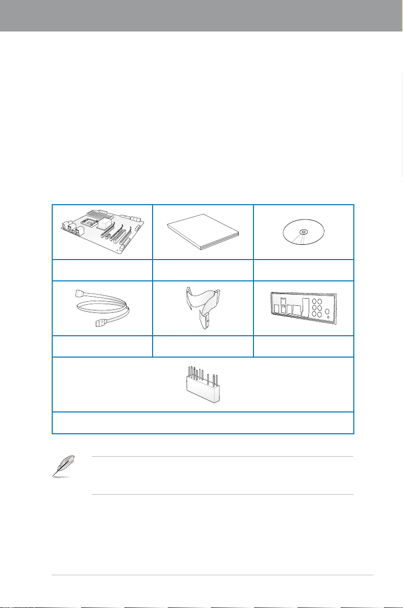
1.2 Package contents
Check your motherboard package for the following items.
Chapter 1
ASUS P5QD Turbo
motherboard
4 x Serial ATA signal cables
• If any of the above items is damaged or missing, contact your retailer.
• The illustrated items above are for reference only. Actual product specications may
vary with different models.
User guide Support DVD
1 x Ultra DMA 133/
100/66 cable
1 x ASUS Q-Connector kit
1 x ASUS Q-Shield
ASUS P5QD Turbo 1-1
Page 16

1.3 Special features
1.3.1 Product highlights
Chapter 1
LGA775 Intel® Core™2 Processor Ready
This motherboard supports the latest Intel® Core™2 processors in the LGA775 package. It
also supports Intel® 45nm multi-core CPUs. With the new Intel® Core™ microarchitecture and
1600 / 1333 / 1066 / 800 MHz FSB, Intel® Core™2 processor is one of the most powerful and
energy efcient CPU in the world.
Intel® P45 Chipset
The Intel® P45 Chipset supports dual-channel DDR2 800/667 MHz memory architecture,
1333/1066/800 MHz FSB (Front Side Bus), PCIe 2.0, and multi-core CPUs. It especially
includes Intel® Fast Memory Access technology that signicantly optimizes the use of available
memory bandwidth and reduces the latency of the memory accesses.
Dual-Channel DDR2 1300 support
The motherboard supports DDR2 memory that features data transfer rates of 1300 /1200
/ 1066 / 800 / 667 MHz to meet the higher bandwidth requirements of the latest operation
system, 3D graphics, multimedia, and Internet applications. The dual-channel DDR2
architecture doubles the bandwidth of your system memory to boost system performance,
eliminating bottlenecks with peak bandwidths of up to 20.8 GB/s.
100% high-quality conductive polymer capacitors
This motherboard uses all high-quality conductive polymer capacitors for durability, improved
lifespan, and enhanced thermal capacity.
Green ASUS
This motherboard and its packaging comply with the European Union’s Restriction on the
use of Hazardous Substances (RoHS). This is in line with the ASUS vision of creating
environment-friendly and recyclable products/packaging to safeguard consumers’ health
while minimizing the impact on the environment.
1.3.2 ASUS special features
ASUS 8-Phase Power Design
With power efciency so important to operating temperatures, ASUS 8-Phase VRM design
leads the industry with its 96% power efciency. High quality power components such as low
RDS (on) MOSFETs for minimum switching loss & lower temperatures, Ferrite core chokes
with lower hysteresis loss, and high quality Japanese-made conductive polymer capacitors
all add up to ensure longer component life and lower power loss—creating more energy
efciency.
1-2 Chapter 1: Product Introduction
Page 17

Express Gate
Taking only 5 seconds to bootup, Express Gate is the one-stop gateway to instant fun! It’s a
unique motherboard built-in OS. You can utilize the most popular Instant Messengers (IM)
like MSN, Skype, Google talk, QQ, and Yahoo! Messenger to keep in touch with friends,
or quickly check on the weather and e-mails just before leaving your house. What’s more,
the user-friendly picture manager lets you view your pictures without entering Windows at
anytime!
The actual boot time is subject to hardware congurations and product models.
ASUS Power Saving Solution
ASUS Power Saving solution intelligently and automatically provides balanced computing
power and energy consumption.
ASUS EPU
The ASUS EPU (Energy Processing Unit) provides total system power management by
detecting current PC loadings and intelligently moderating power usage for critical PC
components in real-time–helping save power and money!
ASUS Quiet Thermal Solutions
ASUS Quiet Thermal solutions make the system more stable and enhance the overclocking
capability.
Fanless Design—Unique stylish heatsink
The brand new 2-color heatsink features 0-dB thermal solution that offers users a
noiseless PC environment. The Paten Pending 2-color design within the beautifully
curved ns upgrades the visual enjoyment for the motherboard users, and also
effectively cools down hot airows generated by the north bridge chipset. Combined
with usability and aesthetics, the ASUS Patent 2-color Wing heatsink will give users an
extremely silent and cooling experience with the elegant appearance!
Chapter 1
Fan Xpert
ASUS Fan Xpert intelligently allows you to adjust both the CPU and chassis fan speeds
according to different ambient temperatures caused by different climate conditions
in different geographic regions and your PC’s loading. The built-in variety of useful
proles offer exible controls of fan speed to achieve a quiet and cool environment.
ASUS EZ DIY
ASUS EZ DIY feature collection provides you with easy ways to install computer components,
update the BIOS, or back up your favorite settings.
ASUS Drive Xpert
Without drivers or BIOS setups, the ASUS exclusive Drive Xpert is ideal for anyone
who needs to secure data on their hard drives or enhance hard drive performances
without the hassles of complicated congurations. With Drive Xpert’s user-friendly
graphical user interface, you can easily arrange hard drive backups or enhance their
hard drive transfer rates - ensuring that data is looked after every moment, every day.
ASUS P5QD Turbo 1-3
Page 18

ASUS CrashFree BIOS 3
ASUS CrashFree BIOS 3 allows you to restore corrupted BIOS data from a USB ash
disk containing the BIOS le. This protection eliminates the need to buy a replacement
Chapter 1
ROM chip.
ASUS Q-Shield
ASUS Q-Shield’s special design makes it convenient and easy to install on your
motherboard. With better electric conductivity, it ideally protects your motherboard
against static electricity and shields it against Electronic Magnetic Interference (EMI).
ASUS Q-Connector
ASUS Q-Connector allows you to easily connect or disconnect the chassis front panel
cables to the motherboard. This unique module eliminates the trouble of connecting the
system panel cables one at a time and avoiding wrong cable connections.
ASUS EZ Flash 2
ASUS EZ Flash 2 is a user-friendly utility that allows you to update the BIOS without
using a bootable oppy disk or an OS-based utility.
ASUS O.C. Prole
The motherboard features the ASUS O.C. Prole that allows you to conveniently store
or load multiple BIOS settings. The BIOS settings can be stored in the CMOS or a
separate le, giving you the freedom to share and distribute your favorite settings.
1.3.3 ASUS exclusive overclocking features
TurboV
Feel the adrenaline rush of real-time OC—now a reality with the ASUS TurboV. This easy OC
tool allows you to overclock without exiting or rebooting the OS; and its user-friendly interface
makes overclock with just a few clicks away. Moreover, the ASUS OC proles in TurboV
provides the best O.C. settings in different scenarios.
Turbo Key
ASUS Turbo Key allows you to turn the PC power button into a physical overclocking button.
After the easy setup, Turbo Key can boost performances without interrupting ongoing work or
games, simply through pressing the button
Precision Tweaker 2
Allows you to adjust the CPU voltage in 0.00625v steps and NB/DRAM voltage in 0.02v
steps to ne-tune voltage to achieve the most precise setting for the ultimate overclocking
conguration.
C.P.R. (CPU Parameter Recall)
The BIOS C.P.R. feature automatically restores the CPU default settings when the system
hangs due to overclocking failure. C.P.R. eliminates the need to open the system chassis and
clear the RTC data. Simply shut down and reboot the system, and the BIOS automatically
restores the CPU parameters to their default settings.
1-4 Chapter 1: Product Introduction
Page 19
Chapter 2
Chapter 2: Hardware information
2.1 Before you proceed
Take note of the following precautions before you install motherboard components or change
any motherboard settings.
• Unplug the power cord from the wall socket before touching any component.
• Before handling components, use a grounded wrist strap or touch a safely grounded
object or a metal object, such as the power supply case, to avoid damaging them due
to static electricity.
• Hold components by the edges to avoid touching the ICs on them.
• Whenever you uninstall any component, place it on a grounded antistatic pad or in the
bag that came with the component.
• Before you install or remove any component, ensure that the ATX power supply is
switched off or the power cord is detached from the power supply. Failure to do so
may cause severe damage to the motherboard, peripherals, or components.
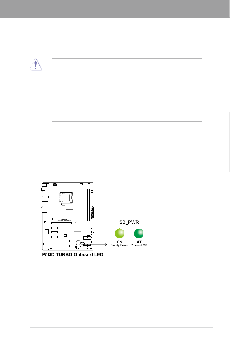
Onboard LED
The motherboard comes with a standby power LED. The green LED lights up to indicate
that the system is ON, in sleep mode, or in soft-off mode. This is a reminder that you should
shut down the system and unplug the power cable before removing or plugging in any
motherboard component. The illustration below shows the location of the onboard LED.
Chapter 2
ASUS P5QD Turbo 2-1
Page 20
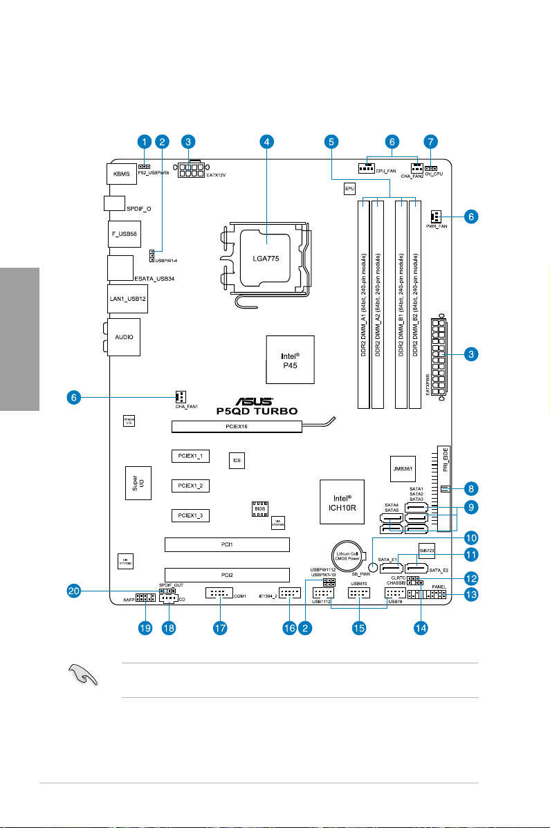
2.2 Motherboard overview
2.2.1 Motherboard layout
Chapter 2
Refer to
2.7 Connectors
connectors.
2-2 Chapter 2: Hardware information
for more information about rear panel connectors and internal
Page 21

2.2.2 Layout contents
Connectors/Jumpers/Slots Page
1. Keyboard/mouse power (3-pin PS2_USBPW56)
2. USB device wake-up (3-pin USBPW1-4, USBPW7-10, USBPW1112)
3. ATX power connectors (24-pin EATXPWR, 8-pin EATX12V)
4. LGA775 CPU socket
5. DDR2 DIMM slots
6. CPU, chassis, and power fan connectors
(4-pin CPU_FAN, 3-pin CHA_FAN1–2, 3-pin PWR_FAN)
7. CPU overvoltage setting (3-pin OV_CPU)
8. IDE connector (40-1 pin PRI_EIDE)
9. ICH10R Serial ATA connectors (7-pin SATA1–5 [Red])
10. Standby power LED (SB_PWR)
11. Silicon Image
(7-pin SATA_E1 [orange, port 0], 7-pin SATA_E2 [white, port 1])
12. Clear RTC RAM (3-pin CLRTC)
13. System panel connector (20-8 pin PANEL)
14. Chassis intrusion connector (4-1 pin CHASSIS)
15. USB connectors (10-1 pin USB78, USB910, USB1112)
16. IEEE 1394a port connector (10-1 pin IE1394_2)
17. Serial port connector (10-1 pin COM1)
18. Optical drive audio connector (4-pin CD)
19. Front panel audio connector (10-1 pin AAFP)
20. Digital audio connector (4-1 pin SPDIF_OUT)
®
Sil5723 Serial ATA RAID connectors
2-24
2-24
2-35
2-5
2-10
2-33
2-22
2-25
2-29
2-1
2-30
2-21
2-37
2-34
2-31
2-32
2-32
2-31
2-36
2-34
Chapter 2
ASUS P5QD Turbo 2-3
Page 22
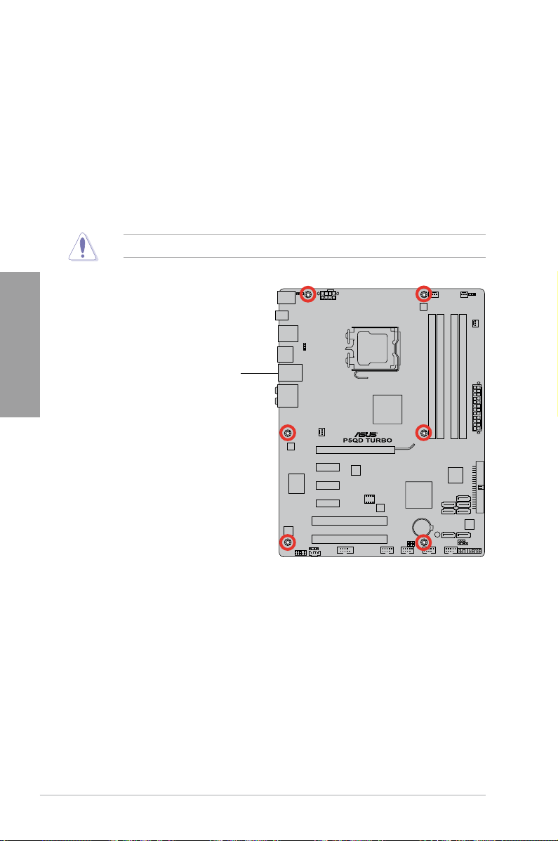
2.2.3 Placement direction
When installing the motherboard, ensure that you place it into the chassis in the correct
orientation. The edge with external ports goes to the rear part of the chassis as indicated in
the image below.
2.2.4 Screw holes
Place six screws into the holes indicated by circles to secure the motherboard to the chassis.
Chapter 2
DO NOT overtighten the screws! Doing so can damage the motherboard.
Place this side towards
the rear of the chassis
2-4 Chapter 2: Hardware information
Page 23
2.3 Central Processing Unit (CPU)
The motherboard comes with a surface mount LGA775 socket designed for the Intel®
Core™2 Extreme / Core™2 Quad / Core™2 Duo / Pentium® Dual-Core / Celeron® Dual-Core
/ Celeron® processors.
• Ensure that all power cables are unplugged before installing the CPU.
• If installing a dual-core CPU, connect the chassis fan cable to the CHA_FAN1
connector to ensure system stability.
• Due to the chipset limitation, we recommend that you use FSB 800MHz CPU or
above.
• Upon purchase of the motherboard, ensure that the PnP cap is on the socket and
the socket contacts are not bent. Contact your retailer immediately if the PnP cap
is missing, or if you see any damage to the PnP cap/socket contacts/motherboard
components. ASUS will shoulder the cost of repair only if the damage is shipment/
transit-related.
• Keep the cap after installing the motherboard. ASUS will process Return Merchandise
Authorization (RMA) requests only if the motherboard comes with the cap on the
LGA775 socket.
• The product warranty does not cover damage to the socket contacts resulting from
incorrect CPU installation/removal, or misplacement/loss/incorrect removal of the PnP
cap.
2.3.1 Installing the CPU
To install a CPU:
Chapter 2
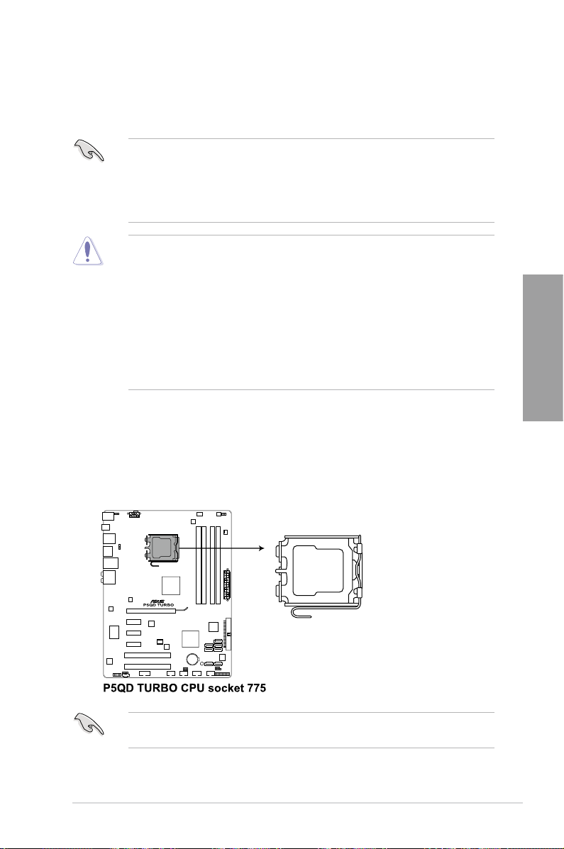
1. Locate the CPU socket on the motherboard.
Before installing the CPU, ensure that the cam box is facing towards you and the load lever
is on your left.
ASUS P5QD Turbo 2-5
Page 24
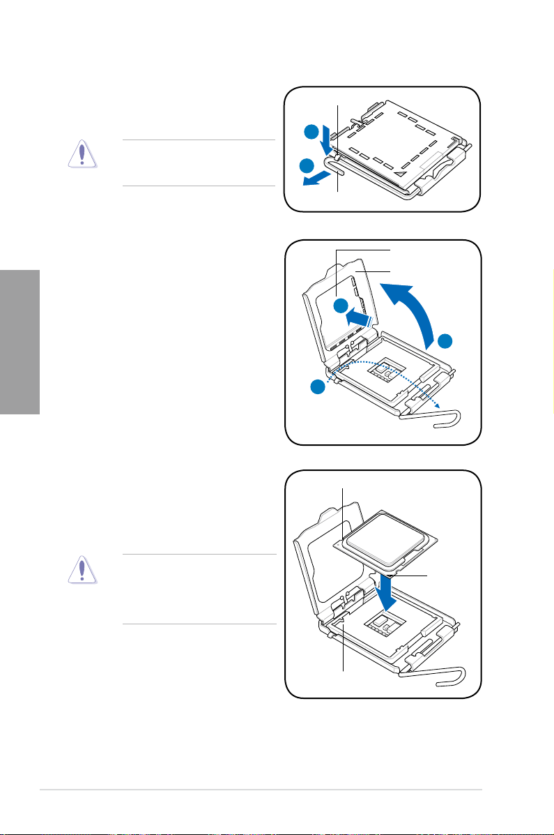
2. Press the load lever with your thumb
(A), then move it to the left (B) until it is
released from the retention tab.
To prevent damage to the socket pins,
do not remove the PnP cap unless
you are installing a CPU.
Retention tab
A
B
Load lever
3. Lift the load lever in the direction of the
arrow to a 135º angle.
Chapter 2
4. Lift the load plate with your thumb and
forenger to a 100º angle (4A), then
push the PnP cap from the load plate
window to remove (4B).
5. Position the CPU over the socket,
ensuring that the gold triangle is on the
bottom-left corner of the socket, and then
t the socket alignment key into the CPU
notch.
The CPU ts in only one correct
orientation. DO NOT force the CPU
into the socket to prevent bending
the connectors on the socket and
damaging the CPU!
4B
3
CPU notch
PnP cap
Load plate
4A
Gold triangle
mark
Alignment key
2-6 Chapter 2: Hardware information
Page 25
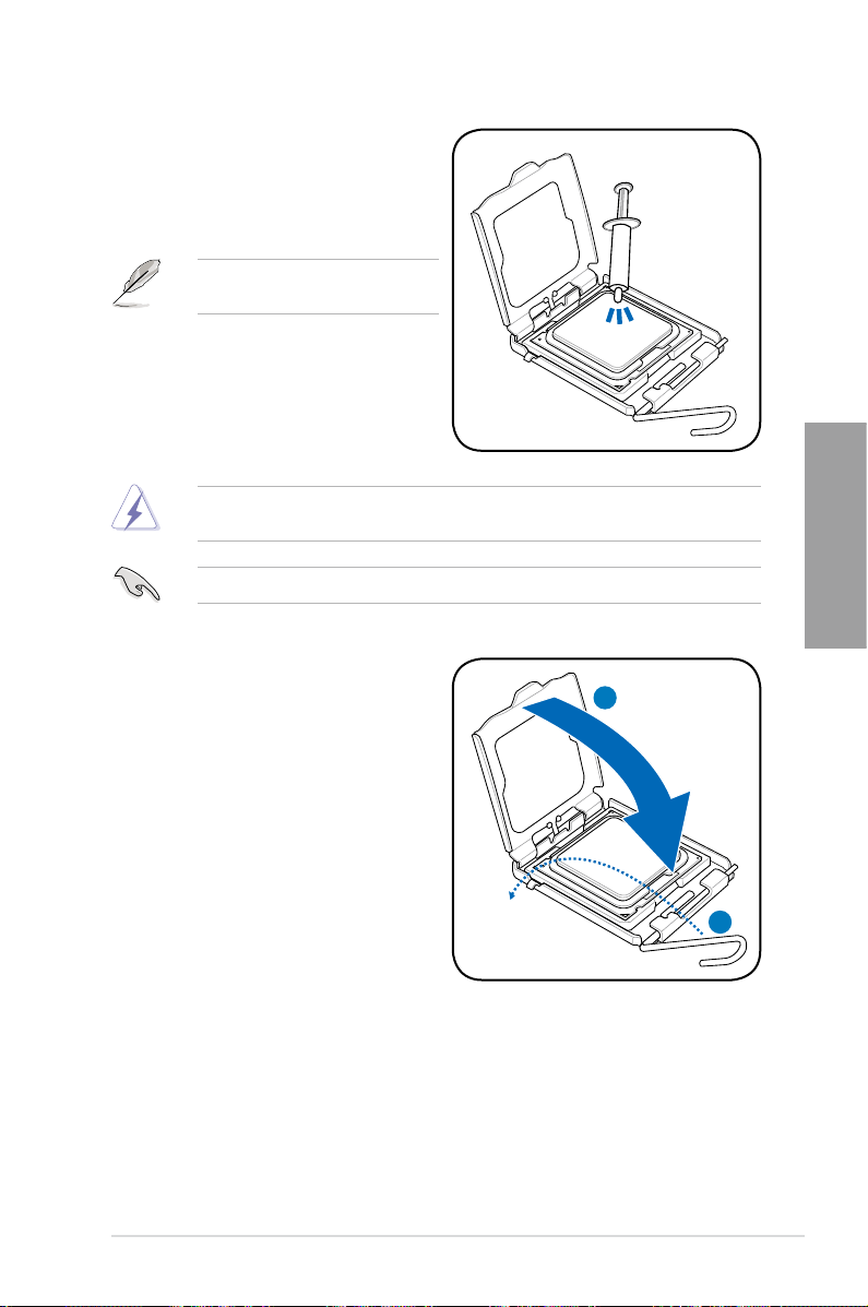
6. Apply some Thermal Interface Material
to the exposed area of the CPU that the
heatsink will be in contact with, ensuring
that it is spread in an even thin layer.
Some heatsinks come with pre-applied
thermal paste. If so, skip this step.
The Thermal Interface Material is toxic and inedible. DO NOT eat it. If it gets into your eyes
or touches your skin, wash it off immediately, and seek professional medical help.
To prevent contaminating the paste, DO NOT spread the paste with your nger directly.
7. Close the load plate (A), then push
the load lever (B) until it snaps into the
retention tab.
Chapter 2
A
B
ASUS P5QD Turbo 2-7
Page 26
2.3.2 Installing the CPU heatsink and fan
The Intel® LGA775 processor requires a specially designed heatsink and fan assembly to
ensure optimum thermal condition and performance.
• When you buy a boxed Intel® processor, the package includes the CPU fan and
heatsink assembly. If you buy a CPU separately, ensure that you use only Intel®-certied
multi-directional heatsink and fan.
®
• Your Intel
Ensure that you have installed the motherboard to the chassis before you install the CPU
fan and heatsink assembly.
LGA775 heatsink and fan assembly comes in a push-pin design and
requires no tool to install.
Chapter 2
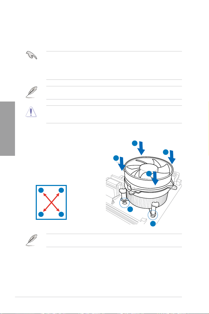
To install the CPU heatsink and fan:
1. Place the heatsink on top of the installed
CPU, ensuring that the four fasteners
match the holes on the motherboard.
2. Push down two fasteners at a time in
a diagonal sequence to secure the
heatsink and fan assembly in place.
If you purchased a separate CPU heatsink and fan assembly, ensure that the Thermal
Interface Material is properly applied to the CPU heatsink or CPU before you install the
heatsink and fan assembly.
A
B
B
A
A
B
B
1
A
1
Orient the heatsink and fan assembly such that the CPU fan cable is closest to the CPU fan
connector.
2-8 Chapter 2: Hardware information
Page 27
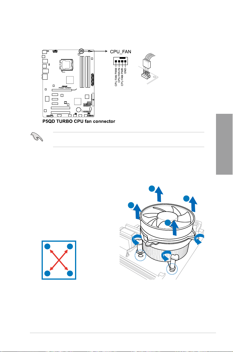
3. Connect the CPU fan cable to the connector on the motherboard labeled CPU_FAN.
DO NOT forget to connect the CPU fan connector! Hardware monitoring errors can occur if
you fail to plug this connector.
2.3.3 Uninstalling the CPU heatsink and fan
To uninstall the CPU heatsink and fan:
1. Disconnect the CPU fan cable from the
connector on the motherboard.
2. Rotate each fastener counterclockwise.
3. Pull up two fasteners at a time in a
diagonal sequence to disengage the
heatsink and fan assembly from the
motherboard.
B
A
B
A
Chapter 2
A
B
B
A
4. Carefully remove the heatsink and fan assembly from the motherboard.
ASUS P5QD Turbo 2-9
Page 28
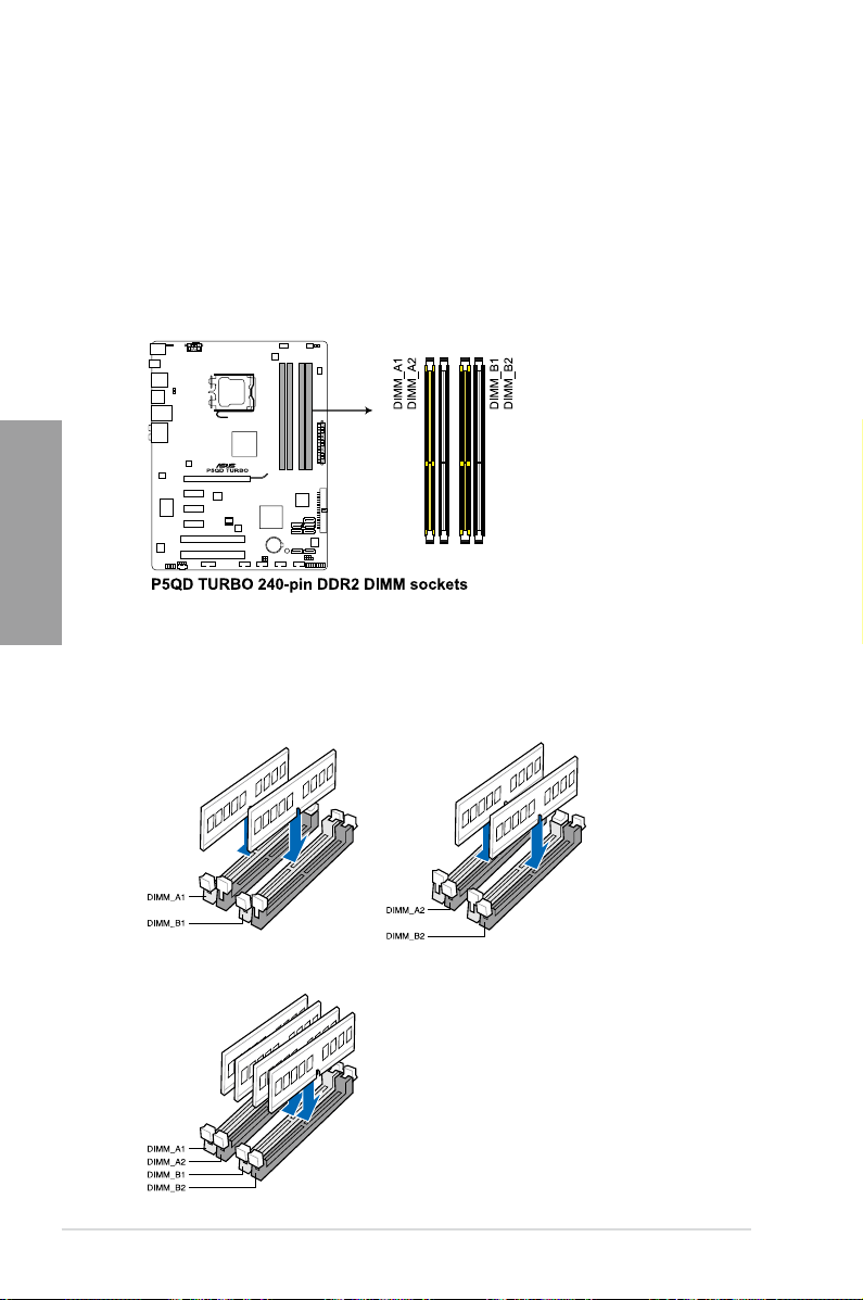
2.4 System memory
2.4.1 Overview
The motherboard comes with four Double Data Rate 2 (DDR2) Dual Inline Memory Modules
(DIMM) sockets.
A DDR2 module has the same physical dimensions as a DDR DIMM but has a 240-pin
footprint compared to the 184-pin DDR DIMM. DDR2 DIMMs are notched differently to
prevent installation on a DDR DIMM socket.
The gure illustrates the location of the DDR2 DIMM sockets:
Chapter 2
Recommended memory congurations
One DIMM:
You may install one memory module in any slot as a single-channel operation.
Two DIMMs (dual-channel operation):
Four DIMMs (dual-channel operation):
2-10 Chapter 2: Hardware information
Page 29

2.4.2 Memory congurations
You may install 512MB, 1GB, 2GB and 4GB unbuffered ECC and non-ECC DDR2 DIMMs
into the DIMM sockets.
• You may install varying memory sizes in Channel A and Channel B. The system maps
the total size of the lower-sized channel for the dual-channel conguration. Any excess
memory from the higher-sized channel is then mapped for single-channel operation.
• We recommend that you install the memory modules from the yellow slots for better
overclocking capability.
• Always install DIMMs with the same CAS latency. For optimum compatibility, it is
recommended that you obtain memory modules from the same vendor.
• Due to the memory address limitation on 32-bit Windows OS, when you install 4GB
or more memory on the motherboard, the actual usable memory for the OS can be
about 3GB or less. For effective use of memory, we recommend that you do any of the
following:
- Use a maximum of 3GB system memory if you are using a 32-bit Windows OS.
- Install a 64-bit Windows OS when you want to install 4GB or more on the
motherboard.
• This motherboard does not support DIMMs made up of 256 megabit (Mb) chips or
less.
• The default memory operation frequency is dependent on its Serial Presence Detect
(SPD), which is the standard way of accessing information from a memory module.
Under the default state, some memory modules for overclocking may operate at a
lower frequency than the vendor-marked value. To operate at the vendor-marked or at
a higher frequency, see section 3.5 Ai Tweaker menu for manual memory frequency
adjustment.
• For system stability, use a more efcient memory cooling system to support a full
memory load (4 DIMMs) or overclocking condition.
Chapter 2
ASUS P5QD Turbo 2-11
Page 30
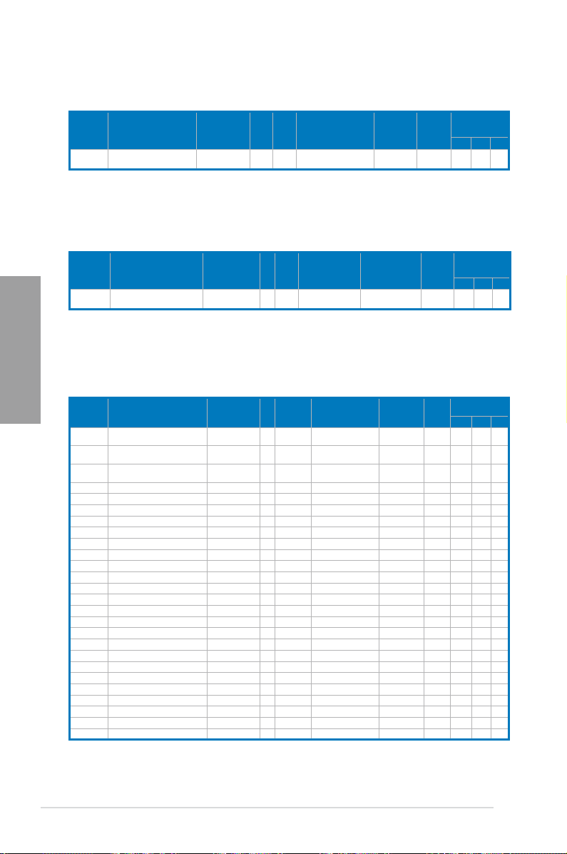
P5QD Turbo Motherboard Qualified Vendors Lists (QVL)
DDR2-1300 MHz capability
Vendor Part No. Size SS/DS
Team TXDD1024M1300HC6 1024MB DS N/A Heat-Sink Package 6-6-6-18 2.35-2.45 V
P5QD Turbo Motherboard Qualified Vendors Lists (QVL)
DDR2-1200 MHz capability
Vendor Part No. Size
Chapter 2
KINGSTON KHX9600D2K2/2G 2048MB(Kit of 2) DS N/A Heat-Sink Package 2.3-2.35 V
P5QD Turbo Motherboard Qualified Vendors Lists (QVL)
DDR2-1066 MHz capability
Vendor Part No. Size
Apacer
Apacer
CORSAIR
Crucial BL12864AA106A.8FE5 (EPP) 1024MB SS N/A Heat-Sink Package 5-5-5-15 2.0 V V V
Crucial BL12864AA1065.16FD5 (EPP) 1024MB DS N/A Heat-Sink Package 5 V V V
G.SKILL F2-8500CL5S-1GBPK 1024MB DS N/A Heat-Sink Package 5-5-5-15 2.0-2.1 V V V
G.SKILL F2-8500CL5D-2GBPK 2048MB(Kit of 2) DS N/A Heat-Sink Package 5-5-5-15 2.0-2.1 V V V
G.SKILL F2-8500CL5D-4GBPK 4096MB(Kit of 2) DS N/A Heat-Sink Package 5-5-5-15 2.0-2.1 V V
GEIL GB22GB8500C5DC 2048MB(Kit of 2) SS GEIL GL2L128M88BA25AB 5-5-5-15 2.2-2.4 V V V
GEIL GE22GB1066C5DC 2048MB(Kit of 2) SS N/A Heat-Sink Package 5-5-5-15 2.2-2.4 V V V
GEIL GE24GB1066C5QC 4096MB(Kitof4) SS N/A Heat-Sink Package 5-5-5-15 2.2-2.4 V V V
GEIL GB24GB8500C5DC 4096MB(Kit of 2) DS GEIL GL2L128M88BA25AB 5-5-5-15 2.2-2.4 V V V
GEIL GE24GB1066C5DC 4096MB(Kit of 2) DS N/A Heat-Sink Package 5-5-5-15 2.2-2.4 V V V
GEIL GX24GB8500C5UDC 4096MB(Kit of 2) DS N/A Heat-Sink Package 5-5-5-15 2.2-2.4 V V V
GEIL GB24GB8500C5QC 4096MB(Kitof4) DS GEIL GL2L128M88BA25AB 5-5-5-15 2.2-2.4 V V V
Hynix HYMP564U64FP8-G7 512MB SS HYNIX HY5PS12821FFP-G7 7 V V V
Hynix HYMP 512U64FP8-G7 1024MB DS HYNIX HY5PS12821FFP-G7 7-7-7-12 V V V
KINGMAX KLED48F-A8KI5-EPA 1024MB DS KINGMAX KKA8FEIBF-HJK-18A V V V
KINGSTON KHX8500D2/ 512 512MB SS Heat-Sink Package V V V
KINGSTON KHX8500D2K2/1G 1024MB(Kit of 2) SS N/A Heat-Sink Package 2.2 V V V
KINGSTON KHX8500D2/1G 1024MB DS N/A Heat-Sink Package 2.2 V V V
KINGSTON KVR1066D2N7/1G 1024MB DS ELPIDA E5108AJBG-1J-E 1066-5-5-5-15 1.8 V V V
KINGSTON KHX8500D2K2/2G 2048MB(Kit of 2) DS N/A Heat-Sink Package 2.2 V V V
KINGSTON KHX8500D2K2/2GN (EPP) 2048MB(Kit of 2) DS N/A Heat-Sink Package 2.2 V V V
MICRON MT8HTF12864AY-1GAE1 1024MB SS MICRON D9JKH 7 V V V
MICRON MT16HTF25664AY-1GAE1 2048MB DS MICRON D9JKH 7 V V V
BoxP/N:CH.02GAF.C0KK2
(78.0AG9S.9KF)
BoxP/N:CH.04GAF.F0KK2
(78.AAGAL.9KF)
BoxP/N:TWIN2X4096-8500C5DF
(CM2X2048-8500C5D)(EPP)
DIMM socket
Chip
Chip NO.
Brand
SS/DSChip
Chip NO.
Brand
SS/DSChip
2048MB(Kit of 2) DS N/A Heat-Sink Package 5-5-5-15 V V V
4096MB(Kit of 2) DS N/A Heat-Sink Package 5-5-5-15 V V V
4096MB(Kit of 2) DS N/A Heat-Sink Package 5-5-5-15 2.1 V V V
Brand
Chip NO.
Timing
Dimm (Bios)
Timing Dimm
(Bios)
Timing Dimm
(Bios)
Voltage
Voltage
Voltage
support
(Optional)
A* B* C*
DIMM socket
support
(Optional)
A* B* C*
DIMM socket
support (Optional)
A* B* C*
2-12 Chapter 2: Hardware information
Page 31

P5QD Turbo Motherboard Qualified Vendors Lists (QVL)
DDR2-1066 MHz capability (cont.)
Vendor Part No. Size
OCZ OCZ2N10662GK(EPP) 2048MB(Kit of 2) DS Heat-Sink Package V V V
OCZ OCZ2N1066SR2GK(EPP)
OCZ OCZ2RPR10664GK 4096MB(Kit of 2) DS N/A Heat-Sink Package 5 2.2 V V
SAMSUNG M378T2953GZ3-CF8 1024MB DS SAMSUNG K4T51083QG 7 V V V
Transcend TX1066QLU-2GK 2048MB(Kit of 2) SS ELPIDA Heat-Sink Package 5 V V V
Transcend TX1066QLU-4GK 4096MB(Kit of 2) DS N/A Heat-Sink Package 5 V V V
BoxP/N:AXT760UD00-19D-K-2G
Aeneon
(AXT760UD00-19D)
BUFFALO FSX1066D2C-1G
BUFFALO FSX1066D2C-K4G 2048MB DS N/A Heat-Sink Package 5-5-5-15 V V V
Elixir M2Y1G64TU8HC4B-BD 1024MB DS Elixir N2TU 51280CE-BD 6 V V V
Kingbox N/A 1024MB DS MICRON 7YDI2 1.8 V V V
Mushkin 996535 2048MB(Kit of 2) DS N/A Heat-Sink Package 5-5-4-12 V V
Mushkin 996612 2048MB(Kit of 2) DS N/A Heat-Sink Package 5-5-5-15 2.1 V V
Mushkin 996619 4096MB(Kit of 2) DS N/A Heat-Sink Package 5-5-5-15 2.0-2.1 V V V
2048MB(Kit of 2) DS
2048MB(Kit of 2) DS N/A Heat-Sink Package 5 V V V
1024MB DS
SS/DSChip
Brand
N/A
N/A
Chip NO.
Heat-Sink Package 5
Heat-Sink Package
Timing Dimm
(Bios)
5-5-5-15
(800-5-5-5-15)
Voltage
2.10 V
DIMM socket
support (Optional)
A* B* C*
V
V
V
P5QD Turbo Motherboard Qualified Vendors Lists (QVL)
DDR2-800 MHz capability
DIMM socket
Vendor Part No. Size
A-DATA M2OAD6H3J4171Q1E52 2048MB DS A-DATA AD20908A8A-25EG V V V
Apacer 78.91G9I.9K5 512MB SS APACER AM4B5708JQJS8E 5 V V V
Apacer 78.01GA0.9K5 1024MB SS APACER AM4B5808CQJS8E 5 V V V
Apacer 78.A1GA0.9K4 2048MB DS APACER AM4B5808CQJS8E 5 V V
CORSAIR CM2X1024-6400C4 1024MB DS N/A Heat-Sink Package 4 1.9 V V
CORSAIR BoxP/N:TWIN2X4096-6400C4DHX
(CM2X2048-6400C4DHX)
CORSAIR BoxP/N:TWIN2X4096-6400C5
(CM2X2048-6400C5)
CORSAIR BoxP/N:TWIN2X4096-6400C5DHX
(CM2X2048-6400C5DHX)
Crucial BL12864AA80A.8FE5(EPP) 1024MB SS N/A Heat-Sink Package 4-4-4-12 2.0 V V V
Crucial BL12864AA804.16FD3 1024MB DS N/A Heat-Sink Package 4 2.2 V V V
Crucial BL12864AA804.16FD 1024MB DS N/A Heat-Sink Package 4 2.2 V V V
Crucial BL12864AL804.16FD3 1024MB DS N/A Heat-Sink Package 4 2.2 V V V
Crucial BL25664AA80A.16FE5(EPP) 2048MB DS N/A Heat-Sink Package 4-4-4-12 2.0 V V V
ELPIDA EBE10EE8ABFA-8E-E 1024MB SS ELPIDA E1108AB-8E-E(ECC) 5 1.7-1.9 V V
G.SKILL F2-6400CL5D-1GBNQ 1024MB(Kit of 2) SS N/A Heat-Sink Package 5-5-5-15 1.8-2.0 V V V
G.SKILL F2-6400CL4D-2GBPK 1024MB DS Heat-Sink Package 4 V V V
G.SKILL F2-6400CL5D-2GBNQ 1024MB DS Heat-Sink Package 5 V V
G.SKILL F2-6400PHU2-2GBNR 1024MB DS Heat-Sink Package 5 V V V
G.SKILL F2-6400CL4D-4GBPK 4096MB(Kit of 2) DS N/A Heat-Sink Package 4 2.0-2.1 V V V
G.SKILL F2-6400CL5D-4GBPQ 4096MB(Kit of 2) DS N/A Heat-Sink Package 5 1.8-1.9 V V V
G.SKILL F2-6400CL6D-4GBMQ 4096MB(Kit of 2) DS N/A Heat-Sink Package 6 1.8-1.9 V V V
G.SKILL F2-6400CL6D-8GBMQ 8192MB(Kit of 2) DS N/A Heat-Sink Package 6-6-6-18 1.8 V V V
GEIL GB22GB6400C4DC 2048MB(Kit of 2) DS GEIL GL2L64M088BA30EB 4-4-4-12 2.0 V V V
GEIL GB22GB6400C5DC 2048MB(Kit of 2) DS GEIL GL2L64M088BA30EB 5-5-5-15 1.8 V V V
GEIL GE22GB800C4DC 2048MB(Kit of 2) DS N/A Heat-Sink Package 4-4-4-12 2.0 V V V
GEIL GE22GB800C5DC 2048MB(Kit of 2) DS N/A Heat-Sink Package 5-5-5-15 1.8 V V
GEIL GX22GB6400DC 2048MB(Kit of 2) DS N/A Heat-Sink Package 5-5-5-15 1.8 V V V
4096MB(Kit of 2) DS N/A Heat-Sink Package 4-4-4-12 2.10 V V V
4096MB(Kit of 2) DS N/A Heat-Sink Package 5-5-5-18 1.80 V V V
4096MB(Kit of 2) DS N/A Heat-Sink Package 5-5-5-18 1.80 V V V
SS/DSChip
Brand
Chip NO.
Timing
Dimm (Bios)
Voltage
support
(Optional)
A* B* C*
V
V
Chapter 2
ASUS P5QD Turbo 2-13
Page 32

P5QD Turbo Motherboard Qualified Vendors Lists (QVL)
DDR2-800 MHz capability (cont.)
Vendor Part No. Size
GEIL GX22GB6400UDC 2048MB(Kit of 2) DS N/A Heat-Sink Package 4-4-4-12 2.1 V V V
GEIL
GEIL GX22GB6400LX 2048MB DS N/A Heat-Sink Package 5-5-5-15 V V V
GEIL GB24GB6400C4DC 4096MB(Kit of 2) DS GEIL GL2L128M88BA25AB 4-4-4-12 2.0 V V V
GEIL GB24GB6400C5DC 4096MB(Kit of 2) DS GEIL GL2L128M88BA25AB 5-5-5-15 1.8 V V
GEIL GB24GB6400C5QC 4096MB(Kit of 2) DS GEIL GL2L64M088BA30EB 5-5-5-15 1.8 V V V
GEIL GE24GB800C4DC 4096MB(Kit of 2) DS N/A Heat-Sink Package 4-4-4-12 2.0 V V V
GEIL
GEIL GX24GB6400DC 4096MB(Kit of 2) DS N/A Heat-Sink Package 5-5-5-15 1.8 V V V
GEIL GB24GB6400C4QC 4096MB(Kitof4) DS GEIL GL2L64M088BA30EB 4-4-4-12 2.0 V V V
GEIL GE24GB800C4QC 4096MB(Kitof4) DS N/A Heat-Sink Package 4-4-4-12 2.0 V V
GEIL GE24GB800C5QC 4096MB(Kitof4) DS N/A Heat-Sink Package 5-5-5-15 1.8 V V V
GEIL GB28GB6400C4QC 8192MB(Kitof4) DS GEIL GL2L128M88BA25AB 4-4-4-12 2.0 V V V
Chapter 2
GEIL GB28GB6400C5QC 8192MB(Kitof4) DS GEIL GL2L128M88BA25AB 5-5-5-15 1.8 V V V
GEIL GE28GB800C4QC 8192MB(Kitof4) DS N/A Heat-Sink Package 4-4-4-12 2.0 V V V
GEIL GE28GB800C5QC 8192MB(Kitof4) DS N/A Heat-Sink Package 5-5-5-15 1.8 V V V
Hynix HYMP564U64CP8-S5 512MB SS HYNIX HY5PS12821CFP-S5 5 1.8 V V V
Hynix HYMP112U64CP8-S6 1024MB SS HYNIX HY5PS1G831CFP-S6 6 V V V
Hynix HYMP 512U64CP8-S5 1024MB DS HY5PS12821CFP-S5 5 V
KINGMAX KLDC28F-A8KI5 512MB SS KINGMAX KKA8FEIBF-HJK-25A V V V
KINGMAX KLDD48F-ABKI5 1024MB DS KINGMAX KKA8FEIBF-HJK-25A V V V
KINGMAX KLDE88F-B8KB5 2048MB DS KINGMAX KKB8FFBXF-CFA-25A V V V
KINGSTON KVR800D2N5/ 512 512MB SS ELPIDA E5108AJBG-8E-E 1.8 V V V
KINGSTON KVR800D2N6/ 512 512MB SS ELPIDA E5108AJBG-8E-E 1.8 V V V
KINGSTON KHX6400D2LLK2/1GN(EPP) 1024MB(Kit of 2) SS N/A Heat-Sink Package 4 2.0 V V V
KINGSTON KVR800D2N5/1G 1024MB SS KINGSTON D1288TPFCGL25U 800-5-5-5-15 1.8 V V V
KINGSTON KHX6400D2LL/1G 1024MB DS N/A Heat-Sink Package 4 2.0 V V V
KINGSTON KVR800D2N5/1G 1024MB DS V59C1 512804QBF25 1.8 V V V
KINGSTON KVR800D2N6/1G 1024MB DS ELPIDA E5108AJBG-8E-E 1.8 V V V
KINGSTON KHX6400D2LLK2/2GN(EPP) 2048MB(Kit of 2) DS N/A Heat-Sink Package V
KINGSTON KHX6400D2ULK2/2G 2048MB(Kit of 2) DS N/A Heat-Sink Package 2.3-2.35 V V
KINGSTON KHX6400D2/2G 2048MB DS N/A Heat-Sink Package 2.0 V V V
KINGSTON KVR800D2N5/2G 2048MB DS ELPIDA E1108ACBG-8E-E 1.8 V V V
KINGSTON KVR800D2N6/4G 4096MB DS ELPIDA E2108ABSE-8G-E V V V
NANYA NT 512T64U88B0BY-25C 512MB SS NT5TU64M8BE-25C 5 V V V
NANYA NT1GT64U8HB0BY-25C 1024MB DS NT5TU64M8BE-25C 5 V V V
NANYA NT1GT64U8HCOBY-25D 1024MB DS NANYA NT5TU64M8CE-25D V V
NANYA NT2GT64U8HC0BY-AC 2048MB DS NANYA NT5TU128M8CE-AC 5 V V V
OCZ OCZ2G8001G 1024MB DS N/A Heat-Sink Package 5 1.8 V V
OCZ OCZ2G8002GK 1024MB DS Heat-Sink Package 5 V
OCZ OCZ2T8002GK(EPP) 1024MB DS N/A Heat-Sink Package 5 1.8 V V V
OCZ OCZ2P800R22GK 2048MB(Kit of 2) DS N/A Heat-Sink Package 4 1.8 V V V
OCZ OCZ2P8004GK 4096MB(Kit of 2) DS N/A Heat-Sink Package 5-4-4 1.8 V V V
OCZ OCZ2G8008GK 8192MB(Kit of 2) DS N/A Heat-Sink Package 5 1.80 V V V
OCZ OCZ2VU80016GQ 8192MB(Kit of 2) DS N/A Heat-Sink Package
PSC AL8E8F73C-8E1 2048MB DS PSC A3R1GE3CFF734MAA0E 5 V V V
Qimonda HYS64T256020EU-2.5-C2 2048MB DS Qimonda HYB18T1G800C2F-2.5 6 V V V
Qimonda HYS64T256020EU-25F-C2 2048MB DS Qimonda HYB18T1G800C2F-25F 5 V V V
Qimonda HYS64T 512020EU-2.5-A 4096MB DS Qimonda HYB18T2G800AF-2.5 6 V V V
Qimonda HYS64T 512020EU-25F-A 4096MB DS Qimonda HYB18T2G800AF-25F 5 V V V
SAMSUNG M378T6553GZS-CF7 512MB SS SAMSUNG K4T51083QG 6 V V V
SAMSUNG M378T2863QZS-CF7 1024MB SS SAMSUNG K4T1G084QQ 6 V V V
SAMSUNG M391T2863QZ3-CF7 1024MB SS SAMSUNG K4T1G084QQ(ECC) 6 V V
SAMSUNG M378T2953GZ3-CF7 1024MB DS SAMSUNG K4T51083QG 6 V V V
SAMSUNG M378T5663QZ3-CF7 2048MB DS SAMSUNG K4T1G084QQ(ECC) 6 V V V
GX22GB6400C4USC
GE24GB800C5DC
2048MB DS
4096MB(Kit of 2) DS
SS/DSChip
Chip NO.
Brand
N/A Heat-Sink Package
N/A Heat-Sink Package
Timing
Dimm (Bios)
5-5-5-15
5-6-6
(800-5-5-5-15)
DIMM socket
support
Voltage
(Optional)
A* B* C*
V
V
1.8 V
1.8 V V V
V
V
2-14 Chapter 2: Hardware information
Page 33

P5QD Turbo Motherboard Qualified Vendors Lists (QVL)
DDR2-800 MHz capability (cont.)
DIMM socket
Vendor Part No. Size
SAMSUNG M391T5663QZ3-CF7 2048MB DS SAMSUNG K4T1G084QQ 6 V V V
M378T5263AZ3-CF7
SAMSUNG
Super Talent T800UA12C4 512MB SS Heat-Sink Package V V V
Super Talent T800UB1GC4 1024MB DS Heat-Sink Package V V V
Transcend JM800QLU-1G 1024MB SS Transcend TQ243ECF8 5 V V V
Transcend TS128MLQ64V8U 1024MB SS ELPIDA E1108ACBG-8E-E 5 V V V
Transcend JM800QLU-2G 2048MB DS Transcend TQ243PCF8 5 V V V
TS256MLQ64V8P
Transcend
Transcend TS256MLQ64V8U 2048MB DS ELPIDA E1108ACBG-8E-E 5 V V V
Transcend TS256MLQ72V8U 2048MB DS ELPIDA E1108ACBG-8E-E(ECC) 5 V V V
Aeneon AET760UD00-25DC08X 1024MB SS AENEON AET03R25DC 5 V V V
Aeneon AET760UD00-25DB97X 1024MB DS AENEON AET93R25DB 5 1.8 V V V
Aeneon AET860UD00-25DC08X 2048MB DS AENEON AET03R25DC 5 V V V
Asint SLY2128M8-JGE 1024MB SS Asint DDRII1208-GE V V V
Asint SLZ2128M8-JGE 2048MB DS Asint DDRII1208-GE V V V
CENTURY 28V2H8 512MB SS HYNIX HY5PS12821BFP-S5 V V
CENTURY 28VOH8 1024MB DS HYNIX HY5PS12821BFP-S5 V V
Elixir M2Y1G64TU88D4B-AC 1024MB SS Elixir N2TU1G80DE-AC 5 V V V
Elixir M2Y1G64TU8HB0B-25C 1024MB DS Elixir N2TU 51280BE-25C 5 1.8 V V V
Elixir M2Y2G64TU8HD4B-AC 2048MB DS Elixir N2TU1G80DE-AC 5 V V V
Kingbox N/A 2048MB DS MICRON D9HNL V V
Kingbox N/A 2048MB DS KINGBOX EPD2128082200E-3 V V V
Mushkin XP2-6400 1024MB SS Heat-Sink Package 4 V V V
Oci 04701G16CZ5D2A 1024MB DS Jnnity 64M8PC6400 5 V V V
Patriot PSD2 51280081 512MB SS PATRIOT PM64M8D2BU-25EC V V V
Patriot PSD21G8002 1024MB DS PATRIOT PM64M8D2BU-25PAC 5 V
Patriot PSD22GB002 2048MB DS PATRIOT PM128M8D2BU-25KC 5 V V V
Patriot PDC24G6400LLK 4096MB(Kit of 2) DS N/A Heat-Sink Package 4-4-4-12 2.2 V V V
Silicon Power SP001GBLRU800S02 1024MB SS S-POWER 10YR9N3 5(5-5-5-15) V V V
Silicon Power SP002GBLRU800S02 2048MB DS S-POWER 10YR9N3 5(5-5-5-15) V V V
UMAX D48002GP1-73BEB 2048MB DS UMAX U2S24D30TP-8E 800-5-5-5-15 V V V
4096MB DS
2048MB DS
SS/DSChip
Chip NO.
Brand
SAMSUNG K4T2G084QA-HCF7
ELPIDA E1108ACBG-BE-E
Timing
Dimm (Bios)
6
6-6-6(800-5-5-5-15)
Voltage
support
(Optional)
A* B* C*
V
V
V V
V
V
Chapter 2
P5QD Turbo Motherboard Qualified Vendors Lists (QVL)
DDR2-667 MHz capability
Vendor Part No. Size
Apacer 78.91G92.9K5 512MB SS APACER AM4B5708JQJS7E 5 V V V
Apacer 78.01G9O.9K5 1024MB SS APACER AM4B5808CQJS7E 5 V V V
Apacer 78.A1G9O.9K4 2048MB DS APACER AM4B5808CQJS7E 5 V V V
CORSAIR VS 512MB667D2 512MB SS N/A 64M8CFEG N/A N/A V V
CORSAIR VS1GB667D2 1024MB DS N/A 64M8CFEG N/A N/A V V V
Crucial BL6464AA663.8FD 512MB SS N/A Heat-Sink Package 3 2.2 V V V
Crucial BL12864AA663.16FD2 1024MB DS N/A Heat-Sink Package 3 2.2 V V V
Crucial BL12864AA663.16FD 1024MB DS N/A Heat-Sink Package 3 2.2 V V V
Crucial BL12864AL664.16FD 1024MB DS N/A Heat-Sink Package 3 2.2 V V V
ELPIDA EBE51UD8AEFA-6E-E 512MB SS ELPIDA E5108AE-6E-E 5 1.7-1.9 V V V
G.SKILL F2-5400PHU2-2GBNT 2048MB(Kit of 2) DS G.Skill D264M8GCF 5-5-5-15 1.8 V V V
G.SKILL F2-5300CL5D-4GBMQ 4096MB(Kit of 2) DS N/A Heat-Sink Package 5-5-5-15 1.8-1.9 V V V
GEIL GX21GB5300SX 1024MB DS N/A Heat-Sink Package V V V
SS/
Chip Brand Chip NO.
DS
Timing
Dimm (Bios)
ASUS P5QD Turbo 2-15
Voltage
DIMM socket
support (Optional)
A* B* C*
Page 34

P5QD Turbo Motherboard Qualified Vendors Lists (QVL)
DDR2-667 MHz capability (cont.)
Vendor Part No. Size
GEIL GX22GB5300LX 2048MB DS N/A Heat-Sink Package 5-5-5-15 V V V
GEIL GX24GB5300LDC
Hynix HYMP112U64CP8-Y5 1024MB SS HYNIX HY5PS1G831CFP-Y5 5 V V V
Hynix HYMP 512U64CP8-Y5 1024MB DS HYNIX HY5PS12821CFP-Y5 5 1.8 V V V
KINGSTON KVR667D2N5/ 512 512MB SS KINGSTON D6408TEBGGL3U 5 1.7-1.9 V V V
KINGSTON KVR667D2E5/1G 1024MB DS ELPIDA E5108AGBG-6E-E(ECC) 1.8 V V V
KINGSTON KVR667D2N5/1G 1024MB DS KINGSTON E5108AGBG-6E-E 1.8 V V V
KINGSTON KVR667D2N5/1G
KINGSTON KVR667D2N5/1G 1024MB DS HYNIX HY5PS12821CFP-Y5 1.8 V V
KINGSTON KVR667D2E5/2G 2048MB DS MICRON D9HNL(ECC) 1.8 V V V
KINGSTON KVR667D2N5/2G 2048MB DS KINGSTON D1288TPFCGL25U 667-5-5-5-15 1.8 V V V
KINGSTON KVR667D2N5/2G 2048MB DS HYNIX HY5PS1G831CFP-Y5 1.8 V V V
NANYA NT 512T64U88B0BY-3C 512MB SS NANYA NT5TU64M8BE-3C 5 1.8 V V V
NANYA
Chapter 2
OCZ OCZ26671024V 1024MB SS Ramos RC1GT084CA0-53EC 5 1.8 V V V
Qimonda HYS64T256020EU-3S-C2 2048MB DS Qimonda HYB18T1GB00C2F-3S 5 V V V
SAMSUNG M378T6553EZS-CE6 512MB SS SAMSUNG K4T51083QE 5 V V V
SAMSUNG M378T2953EZ3-CE6 1024MB DS SAMSUNG K4T51083QE 5 V V V
SAMSUNG M378T5263AZ3-CE6 4096MB DS SAMSUNG K4T2G084QA-HCE6 5 V V V
Super Talent T6UA 512C5 512MB SS N/A Heat-Sink Package 5 1.8 V V V
Super Talent T6UB1GC5 1024MB DS N/A Heat-Sink Package 5 1.8 V V V
TwinMOS 8D-23JK5M2ETP 512MB SS TwinMOS TMM6208G8M30C 5 1.8 V V V
Aeneon AET760UD00-30DB97X 1024MB DS AENEON AET93R30DB 5 1.8 V V V
Aeneon AET860UD00-30DB08X 2048MB DS AENEON AET03F30DB 5 V V V
Asint SLX264M8-J6E 512MB SS Asint DDRII6408-6E V V V
Asint SLY2128M8-J6E 1024MB SS Asint DDRII1208-6E V V V
CENTURY 26V2H8 512MB SS HYNIX HY5PS12821CFP-Y5 5 1.85 V V V
CENTURY 26VOH8 1024MB DS HYNIX HY5PS12821CFP-Y5 5 1.85 V V V
Dynet DNHM5U 512C8FE-A6 512MB SS Dynet DN5HS82CFE-A6 V V
Kingbox N/A 1024MB SS KINGBOX EPD2128082200E-4 V V V
Kingbox N/A 1024MB DS KINGBOX EPD264082200E-4 1.8 V V V
Kingbox N/A 1024MB DS KINGBOX EPD264082200N-4 V V V
MDT M 512-667-8 512MB SS MDT 18D 51280D-30648 4 1.8 V V V
MDT M924-667-16 1024MB DS 18D 51280D-30646E 4 V V
Patriot PSD2 51266781 512MB SS PATRIOT PM64M8D2BU-3KC V V V
Patriot PSD21G6672 1024MB DS PATRIOT PM64M8D2BU-3PAC 5 V V V
NT2GT64U8HB0JY-3C
4096MB(Kit of 2) DS
1024MB DS
2048MB DS
SS/
Chip Brand Chip NO.
DS
N/A
ELPIDA
Timing
Dimm (Bios)
Heat-Sink Package 5-5-5-15
E5108AJBG-8E-E
NT5TU128M8BJ-3C 5
Voltage
1.8 V
1.8 V
DIMM socket
support (Optional)
A* B* C*
V
V
V
V
V
V
SS - Single-sided DS - Double-sided
DIMM support:
• A*: Supports one module inserted in any slot as single-channel memory
conguration.
• B*: Supports one pair of modules inserted into either the yellow slots or the black
slots as one pair of dual-channel memory conguration.
• C*: Supports four modules inserted into both the yellow and black slots as two pairs
of dual-channel memory conguration.
Visit the ASUS website at www.asus.com for the latest QVL.
2-16 Chapter 2: Hardware information
Page 35

2.4.3 Installing a DIMM
Ensure to unplug the power supply before adding or removing DIMMs or other system
components. Failure to do so may cause severe damage to both the motherboard and the
components.
To install a DIMM:
1. Press the retaining clips outward to
unlock a DIMM socket.
2. Align a DIMM on the socket such that
the notch on the DIMM matches the
break on the socket.
Unlocked retaining clip
A DIMM is keyed with a notch so that it ts in only one direction. DO NOT force a DIMM into
a socket to avoid damaging the DIMM.
3. Firmly insert the DIMM into the socket
until the retaining clips snap back in
place and the DIMM is properly seated.
Locked Retaining Clip
2.4.4 Removing a DIMM
To remove a DIMM:
2
DIMM notch
1
1
Chapter 2
3
2
1. Simultaneously press the retaining
clips outward to unlock the DIMM.
1
1
DIMM notch
Support the DIMM lightly with your ngers when pressing the retaining clips. The DIMM
might get damaged when it ips out with extra force.
2. Remove the DIMM from the socket.
ASUS P5QD Turbo 2-17
Page 36

2.5 Expansion slots
In the future, you may need to install expansion cards. The following subsections describe the
slots and the expansion cards that they support.
2.5.1 Installing an expansion card
To install an expansion card:
1. Before installing the expansion card, read the documentation that came with it and
make the necessary hardware settings for the card.
2. Remove the system unit cover (if your motherboard is already installed in a chassis).
Chapter 2
3. Remove the bracket opposite the slot that you intend to use. Keep the screw for later
use.
4. Align the card connector with the slot and press rmly until the card is completely
seated on the slot.
5. Secure the card to the chassis with the screw you removed earlier.
6. Replace the system cover.
2.5.2 Conguring an expansion card
After installing the expansion card, congure it by adjusting the software settings.
1. Turn on the system and change the necessary BIOS settings, if any. See Chapter 3 for
information on BIOS setup.
2. Assign an IRQ to the card. Refer to the tables on the next page.
3. Install the software drivers for the expansion card.
Ensure to unplug the power cord before adding or removing expansion cards. Failure to do
so may cause you physical injury and damage motherboard components.
When using PCI cards on shared slots, ensure that the drivers support “Share IRQ” or that
the cards do not need IRQ assignments. Otherwise, conicts will arise between the two PCI
groups, making the system unstable and the card inoperable. Refer to the table on the next
page for details.
2-18 Chapter 2: Hardware information
Page 37

2.5.3 Interrupt assignments
Standard interrupt assignments
IRQ Priority
0 1 System timer
1 2 Keyboard controller
2 – Re-direct to IRQ#9
3 11 IRQ holder for PCI steering*
4 12 Communications port (COM1)*
5 13 IRQ holder for PCI steering*
6 – Reserved
7 – Reserved
8 3 System CMOS/Real Time Clock
9 4 IRQ holder for PCI steering*
10 5 IRQ holder for PCI steering*
11 6 IRQ holder for PCI steering*
12 7 PS/2 compatible mouse port*
13 8 Numeric data processor
14 9 SATA Primary IDE (legacy mode)
15 10 SATA Secondary IDE (legacy mode)
* These IRQs are usually available for ISA or PCI devices.
IRQ assignments for this motherboard
PCI slot 1 shared – – – – – – –
PCI slot 2 – shared – – – – – –
LAN (L1E) – – shared – – – – –
SATA (5723) shared – – – – – – –
PCIe x16_1 shared – – – – – – –
PCIe x1_1 shared – – – – – – –
PCIe x1_2 – shared – – – – – –
PCIe x1_3 – – shared – – – – –
USB controller 1 – – – – – – – shared
USB controller 2 – – – shared – – – –
USB controller 3 – – shared – – – – –
USB controller 4 shared – – – – – – –
USB controller 5 – – – – – shared – –
USB controller 6 – – shared – – – – –
USB 2.0 controller 1 – – – – – – – shared
USB 2.0 controller 2 – – shared – – – – –
SATA controller 1 – – – shared – – – –
SATA controller 2 – – – – – – shared –
IEEE 1394 – – – shared – – – –
Standard function
A B C D E F G H
Chapter 2
ASUS P5QD Turbo 2-19
Page 38

2.5.4 PCI slots
The PCI slots support cards such as a LAN card, SCSI card, USB card, and other cards that
comply with PCI specications. Refer to the gure below for the location of the slots.
2.5.5 PCI Express x1 slots
This motherboard supports PCI Express x1 network cards, SCSI cards and other cards that
comply with the PCI Express specications. Refer to the gure below for the location of the
slots.
2.5.6 PCI Express 2.0 x16 slot (blue)
This motherboard supports a PCI Express 2.0 x16 graphics card that comply with the PCI
Express specications. Refer to the gure below for the location of the slot.
Chapter 2
PCI Express 2.0 x16 slot (blue)
PCI Express x1 slot 1
PCI Express x1 slot 2
2-20 Chapter 2: Hardware information
PCI slot 1
PCI Express x1 slot 3
PCI slot 2
Page 39

2.6 Jumpers
1. Clear RTC RAM (3-pin CLRTC)
This jumper allows you to clear the Real Time Clock (RTC) RAM in CMOS. You can
clear the CMOS memory of date, time, and system setup parameters by erasing
the CMOS RTC RAM data. The onboard button cell battery powers the RAM data in
CMOS, which include system setup information such as system passwords.
To erase the RTC RAM
1. Turn OFF the computer and unplug the power cord.
2. Move the jumper cap from pins 1-2 (default) to pins 2-3. Keep the cap on pins 2-3
for about 5–10 seconds, then move the cap back to pins 1-2.
3. Plug the power cord and turn ON the computer.
4. Hold down the <Del> key during the boot process and enter BIOS setup to re-enter
data.
Except when clearing the RTC RAM, never remove the cap on CLRTC jumper default
position. Removing the cap will cause system boot failure!
• If the steps above do not help, remove the onboard battery and move the jumper again
to clear the CMOS RTC RAM data. After the CMOS clearance, reinstall the battery.
• You do not need to clear the RTC when the system hangs due to overclocking. For
system failure due to overclocking, use the C.P.R. (CPU Parameter Recall) feature.
Shut down and reboot the system so the BIOS can automatically reset parameter
settings to default values.
• Due to the chipset behavior, AC power off is required to enable C.P.R. function. You
must turn off and on the power supply or unplug and plug the power cord before
rebooting the system.
Chapter 2
ASUS P5QD Turbo 2-21
Page 40

2. CPU overvoltage setting (3-pin OV_CPU)
This jumper allows you to enable or disable the advanced CPU overvoltage setting in
BIOS. Read the following information before you change the jumper setting. Set to pins
1-2 to activate the advanced CPU overvoltage feature.
Chapter 2
OV_CPU
Pins 2-3 (Default) up to 1.70V
Pins 1-2 (OV Enabled) up to 2.10V
• Before you change the jumper setting for extra-high overvoltage ability, use the BIOS
items introduced in
Ensure that your system functions well under the highest BIOS voltage setting before
you change the setting of this jumper.
• Refer to
• DO NOT set the OV_CPU jumper to pins 1-2 when you install a new CPU and have
• The system may need a better cooling system (for example, a water-cooling system)
3.5 Ai Tweaker menu
setting.
not booted for the rst time. Doing so may cause the system to halt. For system failure
due to the wrong setting of the OV_CPU jumper, shut down the computer and move
the cap back to pins 2-3.
to work stably under high voltage settings.
3.5 Ai Tweaker menu
for more information about the CPU overvoltage
rst to adjust the desired CPU performance.
2-22 Chapter 2: Hardware information
Page 41

3. Keyboard/mouse power (3-pin PS2_USBPW56)
This jumper allows you to enable or disable the keyboard/mouse and USB port 5-6
wake-up feature. When you set this jumper to pins 2-3 (+5VSB), you can wake up the
computer by pressing a key on the keyboard (the default is the Space Bar), clicking
the mouse or using a USB device. This feature requires an ATX power supply that can
supply at least 1A on the +5VSB lead, and a corresponding setting in the BIOS. The
USBPW56 jumper is for the rear USB ports.
4. USB device wake-up (3-pin USBPW1-4, USBPW7-10, USBPW1112)
Set these jumpers to +5V to wake up the computer from S1 sleep mode (CPU stopped,
DRAM refreshed, system running in low power mode) using the connected USB
devices. Set to +5VSB to wake up from S3 and S4 sleep modes.
The USBPW1-4 jumper is for the rear USB ports. The USBPW7-10/USBPW1112 jumpers
are for the internal USB connectors that you can connect to additional USB ports.
Chapter 2
• The USB device wake-up feature requires a power supply that can provide 500mA on
the +5VSB lead for each USB port; otherwise, the system will not power up.
• The total current consumed must NOT exceed the power supply capability (+5VSB)
whether under normal condition or in sleep mode.
ASUS P5QD Turbo 2-23
Page 42

2.7 Connectors
2.7.1 Rear panel connectors
Chapter 2
Rear panel connectors
1. PS/2 mouse port (green) 6. PS/2 keyboard port (purple)
2. Optical S/PDIF Out port 7. USB 2.0 ports 5 and 6
3. IEEE 1394a port 8. External SATA port*
4. USB 2.0 ports 3 and 4 9. USB 2.0 ports 1 and 2
5. LAN (RJ-45) port** 10. Audio I/O ports***
* To use hot-plug, set the Controller Mode in the BIOS settings to [AHCI] mode. See
section 3.6.3 Onboard Devices Conguration for details.
2-24 Chapter 2: Hardware information
Page 43

** LAN port LED indications
Activity Link LED Speed LED
Status Description Status Description
OFF
ORANGE Linked ORANGE 100 Mbps connection
BLINKING Data activity GREEN 1 Gbps connection
No link
OFF 10 Mbps connection
ACT/LINK
LED
LAN port
*** Audio 2, 4, 6, or 8-channel conguration
Port
Light Blue Line In Line In Line In Line In
Lime Line Out Front Speaker Out Front Speaker Out Front Speaker Out
Pink Mic In Mic In Mic In Mic In
Orange – – Center/Subwoofer Center/Subwoofer
Black – Rear Speaker Out Rear Speaker Out Rear Speaker Out
Gray – – – Side Speaker Out
Headset
2-channel
4-channel 6-channel 8-channel
2.7.2 Audio I/O connections
Audio I/O ports
SPEED
LED
Chapter 2
Connect to Headphone and Mic
ASUS P5QD Turbo 2-25
Page 44

Connect to Stereo Speakers
Chapter 2
Connect to 2.1 channel Speakers
Connect to 4.1 channel Speakers
2-26 Chapter 2: Hardware information
Page 45

Connect to 5.1 channel Speakers
Connect to 7.1 channel Speakers
Chapter 2
ASUS P5QD Turbo 2-27
Page 46

2.7.3 Internal connectors
1. IDE connector (40-1 pin PRI_EIDE)
The onboard IDE connector is for the Ultra DMA 133/100/66 signal cable. There are
three connectors on each Ultra DMA 133/100/66 signal cable: blue, black, and gray.
Connect the blue connector to the motherboard’s IDE connector, then select one of the
following modes to congure your device.
Chapter 2
Drive jumper setting Mode of device(s) Cable connector
Single device Cable-Select or Master - Black
Black
Black or gray
Two devices
Cable-Select
Master Master
Slave Slave
Master
Slave Gray
• Pin 20 on the IDE connector is removed to match the covered hole on the Ultra DMA
cable connector. This prevents incorrect insertion when you connect the IDE cable.
• Use the 80-conductor IDE cable for Ultra DMA 133/100/66 IDE devices.
If any device jumper is set as “Cable-Select”, ensure that all other device jumpers have the
same setting.
2-28 Chapter 2: Hardware information
Page 47

2. ICH10R Serial ATA connectors (7-pin SATA 1-5)
These connectors are for the Serial ATA signal cables for Serial ATA hard disk drives
and optical disc drives.
If you installed Serial ATA hard disk drives, you can create a RAID 0, 1, 5, and 10
conguration with the Intel® Matrix Storage Technology through the onboard Intel®
ICH10R RAID controller.
Chapter 2
• These connectors are set to Standard IDE mode by default. In Standard IDE mode,
you can connect Serial ATA boot/data hard disk drives to these connectors. If you
intend to create a Serial ATA RAID set using these connectors, set the
item in the BIOS to [RAID]. See section
SATA as
details.
• Before creating a RAID set, refer to section
bundled in the motherboard support DVD.
• You must install Windows
hard disk drives. The Serial ATA RAID feature (RAID 0, 1, 5, and 10) is available only if
you are using Windows® XP SP2 or later version.
• When using hot-plug and NCQ, set the
See section
ASUS P5QD Turbo 2-29
3.4.2 Storage Conguration
®
XP Service Pack 2 or later version before using Serial ATA
3.4.2 Storage Conguration
4.4 RAID congurations
Congure SATA as
for details.
in the BIOS to [AHCI].
Congure
for
or the manual
Page 48

3. Silicon Image® Sil5723 Serial ATA connectors
(7-pin SATA_E1 [orange, port 0], SATA_E2 [white, port 1])
These connectors are for the Serial ATA signal cables for Serial ATA hard disk drives.
If you installed Serial ATA hard disk drives, you can create an
Speed
Image® Sil5723 controller.
Chapter 2
EZ Backup
or a
Super
conguration with the Drive Xpert Technology through the onboard Silicon
Before using the Drive Xpert function, ensure that you have back up all your data in your
hard disks.
•
EZ Backup
SATA_E2 (white, port 1) connector on the motherboard.
•
Super Speed
• The SATA_E1 (orange, port 0) and SATA_E2 (white, port 1) ports are for SATA hard
drives only. ATAPI device is not supported.
Before using the Drive Xpert function, ensure that you have connected the SATA signal
•
cables and installed SATA hard disk drives.
• Drive Xpert function is available only when the hard disk drives connected to SATA_E1
(orange, port 0) and SATA_E2 (white, port 1) connectors are set as data drives.
• When using one hard disk in
(orange, port 0) connector on the motherboard.
• Use the Drive Xpert utility to see both the status of the hard disks connected to
the SATA_E1 (orange, port 0) and SATA_E2 (white, port 1) connectors on the
motherboard. In the BIOS
disk connected to the SATA_E1 connector (orange, port 0) can be detected.
• Clear all previous partitions in the hard disks before you proceed with any mode
changes.
erases all original data/partitions in the hard disk connected to the
erases all original data/partitions in both hard disks.
Normal Mode
menu and the
Main
, connect the hard disk to the SATA_E1
Device Manager
in OS, only the hard
Refer to
4.3.7 ASUS Drive Xpert
2-30 Chapter 2: Hardware information
for detailed application instructions.
Page 49

4. USB connectors (10-1 pin USB78; USB910; USB1112)
These connectors are for USB 2.0 ports. Connect the USB module cable to any of
these connectors, then install the module to a slot opening at the back of the system
chassis. These USB connectors comply with USB 2.0 specication that supports up to
480 Mbps connection speed.
Never connect a 1394 cable to the USB connectors. Doing so will damage the motherboard!
You can connect the front panel USB cable to the ASUS Q-Connector (USB, blue) rst, and
then install the Q-Connector (USB) to the USB connector onboard if your chassis supports
front panel USB ports.
The USB module cable is purchased separately.
5. Optical drive audio connector (4-pin CD)
These connectors allow you to receive stereo audio input from sound sources such as
a CD-ROM, TV tuner, or MPEG card.
Chapter 2
ASUS P5QD Turbo 2-31
Page 50

6. IEEE 1394a port connector (10-1 pin IE1394_2)
This connector is for an IEEE 1394a port. Connect the IEEE 1394a module cable
to this connector, then install the module to a slot opening at the back of the system
chassis.
Chapter 2
7. Serial port connector (10-1 pin COM1)
This connector is for a serial (COM) port. Connect the serial port module cable to this
connector, then install the module to a slot opening at the back of the system chassis.
Never connect a USB cable to the IEEE 1394a connector. Doing so will damage the
motherboard!
The IEEE 1394a module cable is purchased separately.
The COM module is purchased separately.
2-32 Chapter 2: Hardware information
Page 51

8. CPU, chassis, and power fan connectors
(4-pin CPU_FAN; 3-pin CHA_FAN1; 3-pin CHA_FAN2; 3-pin PWR_FAN)
The fan connectors support cooling fans of 350 mA~2000 mA (24 W max.) or a total
of 1 A~7 A (84 W max.) at +12V. Connect the fan cables to the fan connectors on the
motherboard, ensuring that the black wire of each cable matches the ground pin of the
connector.
Do not forget to connect the fan cables to the fan connectors. Insufcient air ow inside the
system may damage the motherboard components. These are not jumpers! Do not place
jumper caps on the fan connectors!
Only the CPU_FAN, CHA_FAN 1 and CHA_FAN 2 connectors support the ASUS Fan Xpert
feature.
Chapter 2
ASUS P5QD Turbo 2-33
Page 52

9. Chassis intrusion connector (4-1 pin CHASSIS)
®
P5QD TURBO
CHASSIS
+5VSB_MB
Chassis Signal
GND
P5QD TURBO Chassis intrusion connector
This connector is for a chassis-mounted intrusion detection sensor or switch. Connect
one end of the chassis intrusion sensor or switch cable to this connector. The chassis
intrusion sensor or switch sends a high-level signal to this connector when a chassis
component is removed or replaced. The signal is then generated as a chassis intrusion
event.
By default , the pin labeled “Chassis Signal” and “Ground” are shorted with a jumper
cap. Remove the jumper caps only when you intend to use the chassis intrusion
detection feature.
Chapter 2
10. Digital audio connector (4-1 pin SPDIF_OUT)
This connector is for an additional Sony/Philips Digital Interface (S/PDIF) port. Connect
the S/PDIF Out module cable to this connector, then install the module to a slot opening
at the back of the system chassis.
The S/PDIF module is purchased separately.
2-34 Chapter 2: Hardware information
Page 53

11. ATX power connectors (24-pin EATXPWR; 8-pin EATX12V)
These connectors are for ATX power supply plugs. The power supply plugs are
designed to t these connectors in only one orientation. Find the proper orientation and
push down rmly until the connectors completely t.
• For a fully congured system, we recommend that you use a power supply unit
(PSU) that complies with ATX 12 V Specication 2.0 (or later version) and provides a
minimum power of 400 W.
• Do not forget to connect the 8-pin EATX +12 V power plug. Otherwise, the system will
not boot.
• We recommend that you use a PSU with higher power output when conguring a
system with more power-consuming devices. The system may become unstable or
may not boot up if the power is inadequate.
• If you are uncertain about the minimum power supply requirement for your system,
refer to the
asus.com/PowerSupplyCalculator/PSCalculator.aspx?SLanguage=en-us for details.
Recommended Power Supply Wattage Calculator
at http://support.
Chapter 2
ASUS P5QD Turbo 2-35
Page 54

12. Front panel audio connector (10-1 pin AAFP)
This connector is for a chassis-mounted front panel audio I/O module that supports
either HD Audio or legacy AC`97 audio standard. Connect one end of the front panel
audio I/O module cable to this connector.
Chapter 2
• We recommend that you connect a high-denition front panel audio module to this
connector to avail of the motherboard’s high-denition audio capability.
• If you want to connect a high-denition front panel audio module to this connector, set
the
Front Panel Type
AC'97 front panel audio module to this connector, set the item to
this connector is set to
item in the BIOS setup to
[HD Audio]
.
[HD Audio];
if you want to connect an
[AC97]
. By default,
2-36 Chapter 2: Hardware information
Page 55

13. System panel connector (20-8 pin PANEL)
This connector supports several chassis-mounted functions.
• System power LED (2-pin PLED)
This 2-pin connector is for the system power LED. Connect the chassis power LED
cable to this connector. The system power LED lights up when you turn on the system
power, and blinks when the system is in sleep mode.
• Hard disk drive activity LED (2-pin IDE_LED)
This 2-pin connector is for the HDD Activity LED. Connect the HDD Activity LED cable
to this connector. The IDE LED lights up or ashes when data is read from or written to
the HDD.
• System warning speaker (4-pin SPEAKER)
This 4-pin connector is for the chassis-mounted system warning speaker. The speaker
allows you to hear system beeps and warnings.
• ATX power button/soft-off button (2-pin PWRSW)
This connector is for the system power button. Pressing the power button turns the
system on or puts the system in sleep or soft-off mode depending on the BIOS settings.
Pressing the power switch for more than four seconds while the system is ON turns the
system OFF.
• Reset button (2-pin RESET)
This 2-pin connector is for the chassis-mounted reset button for system reboot without
turning off the system power.
Chapter 2
ASUS P5QD Turbo 2-37
Page 56

14. ASUS Q-Connector (system panel)
IDE_LED
POWER SW
RESET SW
IDE_LED-
IDE_LED+
PWR
Reset
Ground
Ground
Use the ASUS Q-Connector to connect/disconnect the chassis front panel cables.
To install the ASUS Q-Connector:
1. Connect the front panel cables to the ASUS
Q-Connector.
Refer to the labels on the Q-Connector to
know the detailed pin denitions, and then
match them to their respective front panel
cable labels.
Chapter 2
2. Install the ASUS Q-Connector to the system
panel connector, ensuring the orientation
matches the labels on the motherboard.
The labels on the front panel cables
may vary depending on the chassis
model.
3. The front panel functions are now enabled.
The gure shows the Q-Connector is properly
installed on the motherboard.
2-38 Chapter 2: Hardware information
Page 57

2.8 Starting up for the rst time
1. After making all the connections, replace the system case cover.
2. Be sure that all switches are off.
3. Connect the power cord to the power connector at the back of the system chassis.
4. Connect the power cord to a power outlet that is equipped with a surge protector.
5. Turn on the devices in the following order:
a. Monitor
b. External SCSI devices (starting with the last device on the chain)
c. System power
6. After applying power, the system power LED on the system front panel case lights up.
For systems with ATX power supplies, the system LED lights up when you press the
ATX power button. If your monitor complies with the “green” standards or if it has a
“power standby” feature, the monitor LED may light up or change from orange to green
after the system LED turns on.
The system then runs the power-on self tests or POST. While the tests are running, the
BIOS beeps (see the BIOS beep codes table below) or additional messages appear on
the screen. If you do not see anything within 30 seconds from the time you turned on
the power, the system may have failed a power-on test. Check the jumper settings and
connections or call your retailer for assistance.
BIOS Beep Description
One short beep
One continuous beep followed by two short
beeps then a pause (repeated)
One continuous beep followed by three short
beeps
One continuous beep followed by four short
beeps
VGA detected
Quick boot set to disabled
No keyboard detected
No memory detected
No VGA detected
Hardware component failure
Chapter 2
7. At power on, hold down the <Delete> key to enter the BIOS Setup. Follow the
instructions in Chapter 3.
2.9 Turning off the computer
While the system is ON, pressing the power switch for less than four seconds puts the system
on sleep mode or soft-off mode, depending on the BIOS setting. Pressing the power switch
for more than four seconds lets the system enter the soft-off mode regardless of the BIOS
setting. Refer to section
ASUS P5QD Turbo 2-39
3.7 Power menu
in Chapter 3 for details.
Page 58

Chapter 2
2-40 Chapter 2: Hardware information
Page 59

Chapter 3
Chapter 3: BIOS setup
3.1 Knowing BIOS
BIOS (Basic Input and Output System) stores system hardware settings such as storage
device conguration, overclocking settings, advanced power management, and boot device
conguration that are needed for system startup in the motherboard CMOS. In normal
circumstances, the default BIOS settings apply to most conditions to ensure optimum
performance. We recommend that you not change the default BIOS settings except in
the following circumstances:
• An error message appears on the screen during the system bootup and requests you to
run the BIOS Setup.
• You have installed a new system component that requires further BIOS settings or
update.
Inappropriate settings of the BIOS may result to instability or failure to boot. We strongly
recommend that you change the BIOS settings only with the help of a trained service
personnel.
3.2 Updating BIOS
The ASUS website publishes the latest BIOS versions to provide enhancements on system
stability, compatibility, or performance. However, BIOS updating is potentially risky. If there
is no problem using the current version of BIOS, DO NOT manually update the BIOS.
Inappropriate BIOS updating may result in the system’s failure to boot. Carefully follow the
instructions of this chapter to update your BIOS if necessary.
Visit the ASUS website (www.asus.com) to download the latest BIOS le for this
motherboard.
The following utilities allow you to manage and update the motherboard BIOS setup program.
ASUS Update: Updates the BIOS in Windows® environment.
1.
2.
ASUS EZ Flash 2: Updates the BIOS using a oppy disk or USB ash disk.
3. ASUS CrashFree BIOS utility: Restores the BIOS using the motherboard support
DVD or a USB ash drive when the BIOS le fails or gets corrupted.
Refer to the corresponding sections for details on these utilities.
Save a copy of the original motherboard BIOS le to a USB ash disk in case you need to
restore the BIOS in the future. Copy the original motherboard BIOS using the ASUS Update
utility.
ASUS P5QD Turbo 3-1
Chapter 3
Page 60

3.2.1 ASUS Update utility
The ASUS Update is a utility that allows you to manage, save, and update the motherboard
BIOS in Windows® environment. The ASUS Update utility allows you to:
• Save the current BIOS le
• Download the latest BIOS le from the Internet
• Update the BIOS from an updated BIOS le
• Update the BIOS directly from the Internet
• View the BIOS version information
This utility is available in the support DVD that comes with the motherboard package.
Installing ASUS Update
To install ASUS Update:
1. Place the support DVD in the optical drive.
2. From the Main menu, click the
3. The ASUS Update utility is copied to your system.
Updating the BIOS through the Internet
Chapter 3
To update the BIOS through the Internet:
1. From the Windows® desktop, click
Start > Programs > ASUS >
ASUSUpdate > ASUSUpdate. The
ASUS Update main window appears.
ASUS Update requires an Internet connection either through a network or an Internet
Service Provider (ISP).
Utilities tab, then click Install ASUS Update VX.XX.XX.
Quit all Windows® applications before you update the BIOS using this utility.
2. Select Update BIOS from the
Internet from the drop-down menu,
and then click Next.
3-2 Chapter 3: BIOS setup
Page 61

3. Select the ASUS FTP site nearest
you to avoid network trafc, or click
Auto Select. Click Next.
4. From the FTP site, select the BIOS
version that you wish to download. Click
Next.
5. Follow the onscreen instructions to complete the update process.
The ASUS Update utility is capable of updating itself through the Internet. Always update
the utility to avail all its features.
Updating the BIOS through a BIOS le
To update the BIOS through a BIOS le:
1. Fom the Windows® desktop, click
Start > Programs > ASUS >
ASUSUpdate > ASUSUpdate. The
ASUS Update main window appears.
2. Select
Update BIOS from a le
from the dropdown menu, then click
Next.
3. Locate the BIOS le from the Open
window, then click Open.
4. Follow the onscreen instructions to
complete the update process.
P5QDT.ROM
Chapter 3
P5QDT
Ensure to load the BIOS default
settings to ensure system
compatibility and stability. Select the
Load Setup Defaults item under
the Exit menu. See section 3.10 Exit
Menu for details.
ASUS P5QD Turbo 3-3
Page 62

3.2.2 ASUS EZ Flash 2 utility
The ASUS EZ Flash 2 feature allows you to update the BIOS without having to use a
bootable oppy disk or an OS-based utility.
Before you start using this utility, download the latest BIOS from the ASUS website
at www.asus.com.
To update the BIOS using EZ Flash 2:
1. Insert the USB ash disk that contains the latest BIOS le to the USB port, and then
launch EZ Flash 2 in any of these two ways:
• Press <Alt> + <F2> during POST to display the following.
• Enter the BIOS setup program. Go to the
press <Enter> to enable it.
ASUSTek EZ Flash 2 BIOS ROM Utility V3.34
FLASH TYPE: MXIC 25L8005
Current ROM
BOARD: P5QD Turbo
VER: 0206
DATE: 02/13/2009
PATH: A:\
A:
Tools menu to select EZ Flash 2 and
Update ROM
BOARD: Unknown
VER: Unknown
DATE: Unknown
Chapter 3
Note
[Enter] Select or Load [Tab] Switch [V] Drive Info
[Up/Down/Home/End] Move [B] Backup [Esc] Exit
2. Press <Tab> to switch between drives until the correct BIOS le is found. When
the correct BIOS le is found, EZ Flash 2 performs the BIOS update process and
automatically reboots the system when done.
• This function can support devices such as a USB ash disk with FAT 32/16 format and
single partition only.
• DO NOT shut down or reset the system while updating the BIOS to prevent system
boot failure!
Ensure to load the BIOS default settings to ensure system compatibility and stability.
Select the Load Setup Defaults item under the Exit menu. See section 3.10 Exit Menu for
details.
3-4 Chapter 3: BIOS setup
Page 63

3.2.3 ASUS CrashFree BIOS 3 utility
The ASUS CrashFree BIOS 3 utility is an auto recovery tool that allows you to restore the
BIOS le when it fails or gets corrupted during the updating process. You can restore a
corrupted BIOS le using the motherboard support DVD or a USB ash drive that contains
the BIOS le.
The BIOS le in the motherboard support DVD may be older than the BIOS le published
on the ASUS ofcial website. If you want to use the newer BIOS le, download the le at
support.asus.com and save it to a USB ash drive.
Recovering the BIOS
To recover the BIOS:
1. Turn on the system.
2. Insert the motherboard support DVD to the optical drive, or the USB ash drive
containing the BIOS le to the USB port.
3. The utility automatically checks the devices for the BIOS le. When found, the utility
reads the BIOS le and starts ashing the corrupted BIOS le.
4. Turn off the system after the utility completes the updating process and power on
again.
5. The system requires you to enter BIOS Setup to recover BIOS setting. To ensure
system compatibility and stability, we recommend that you press <F2> to load default
BIOS values.
DO NOT shut down or reset the system while updating the BIOS! Doing so can cause
system boot failure!
ASUS P5QD Turbo 3-5
Chapter 3
Page 64

3.3 BIOS setup program
A BIOS Setup program is provided for BIOS item modication. When you start up the
computer, the system provides you with the opportunity to run this program. Press <Del>
during the Power-On Self-Test (POST) to enter the Setup utility. Otherwise, POST continues
with its test routines.
If you wish to enter Setup after POST, restart the system by pressing <Ctrl> + <Alt> + <Delete>,
or by pressing the reset button on the system chassis. You can also restart by turning the
system off and then back on. Do this last option only if the rst two failed.
The Setup program is designed to make it as easy to use as possible. Being a menu-driven
program, it lets you scroll through the various submenus and select from the available options
using the navigation keys.
• The BIOS setup screens shown in this section are for reference purposes only, and
may not exactly match what you see on your screen.
• If the system becomes unstable after changing any BIOS setting, load the default
settings to ensure system compatibility and stability. Select the Load Setup Defaults
item under the Exit menu. See section 3.10 Exit Menu for details.
• If the system fails to boot after changing any BIOS setting, try to clear the CMOS and
reset the motherboard to the default value. See section 2.6 Jumpers for details.
3.3.1 BIOS menu screen
Chapter 3
3.3.2 Menu bar
The menu bar on top of the screen has the following main items:
Main For changing the basic system conguration
Ai Tweaker For changing the overclocking settings
Advanced For changing the advanced system settings
Power For changing the advanced power management (APM) conguration
Boot For changing the system boot conguration
Tools For conguring options for special functions
Exit For selecting the exit options and loading default settings
Menu items
Main Ai Tweaker Advanced Power Boot Tools Exit
System Time [13:51:25]
System Date [Fri 02/13/2009]
Language [English]
SATA1 [HDT722516DLA380]
SATA2 [Not Detected]
SATA3 [Not Detected]
SATA4 [Not Detected]
SATA5 [Not Detected]
SATA_E1 [Not Detected]
Storage Conguration
System Information
v02.61 (C)Copyright 1985-2008, American Megatrends, Inc.
Submenu items
Conguration elds
BIOS SETUP UTILITY
General helpMenu bar
Use [ENTER], [TAB]
or [SHIFT-TAB] to
select a eld.
Use [+] or [-] to
congure the System
Time.
Select Screen
Select Item
Change Field
+-
Tab Select Field
F1 General Help
F10 Save and Exit
ESC Exit
Navigation keys
3-6 Chapter 3: BIOS setup
Page 65

3.3.3 Navigation keys
At the bottom right corner of a menu screen are the navigation keys for that particular menu.
Use the navigation keys to select items in the menu and change the settings.
The navigation keys may differ from one screen to another.
3.3.4 Menu items
The highlighted item on the menu bar displays the specic items for that menu. For example,
selecting Main shows the Main menu items.
The other items (Advanced, Power, Boot, and Exit) on the menu bar have their respective
menu items.
3.3.5 Submenu items
A solid triangle before each item on any menu screen means that the item has a submenu.
To display the submenu, select the item and press <Enter>.
3.3.6 Conguration elds
These elds show the values for the menu items. If an item is user-congurable, you can
change the value of the eld opposite the item. You cannot select an item that is not
user-congurable.
A congurable eld is enclosed in brackets, and is highlighted when selected. To change the
value of a eld, select it then press <Enter> to display a list of options. Refer to 3.3.7 Pop-up
window.
3.3.7 Pop-up window
Select a menu item then press <Enter> to
display a pop-up window with the conguration
options for that item.
3.3.8 Scroll bar
A scroll bar appears on the right side of a menu
screen when there are items that do not t on
the screen. Press the Up/Down arrow keys or
<Page Up> / <Page Down> keys to display the
other items on the screen.
Pop-up window
Scroll bar
3.3.9 General help
At the top right corner of the menu screen is a brief description of the selected item.
ASUS P5QD Turbo 3-7
Chapter 3
Page 66

3.4 Main menu
When you enter the BIOS Setup program, the Main menu screen appears, giving you an
overview of the basic system information. Select an item and press <Enter> to display the
submenu.
Refer to 3.3.1 BIOS menu screen for information on the menu screen items and how to
navigate through them.
Main Ai Tweaker Advanced Power Boot Tools Exit
System Time [10:55:25]
System Date [Fri 02/13/2009]
Language [English]
SATA1 [HDT722516DLA380]
SATA2 [Not Detected]
SATA3 [Not Detected]
SATA4 [Not Detected]
SATA5 [Not Detected]
SATA_E1 [Not Detected]
Storage Conguration
System Information
3.4.1 SATA 1-5; SATA_E1
While entering Setup, the BIOS automatically detects the presence of SATA devices. There
is a separate submenu for each SATA device. Select a device item then press <Enter> to
display the SATA device information.
Chapter 3
Main
SATA 1
Device : Hard Disk
Vendor : WDC WD800JD-00LSA0
Size : 80.0GB
LBA Mode : Supported
Block Mode : 16 Sectors
PIO Mode : 4
Async DMA : MultiWord DMA-2
Ultra DMA : Ultra DMA-5
SMART Monitoring: Supported
Type [Auto]
LBA/Large Mode [Auto]
Block(Multi-sector Transfer) M [Auto]
PIO Mode [Auto]
DMA Mode [Auto]
SMART Monitoring [Auto]
32Bit Data Transfer [Enabled]
BIOS SETUP UTILITY
v02.61 (C)Copyright 1985-2008, American Megatrends, Inc.
Use [ENTER], [TAB]
or [SHIFT-TAB] to
select a eld.
Use [+] or [-] to
congure System Time.
Select Screen
Select Item
Change Field
+-
Tab Select Field
F1 General Help
F10 Save and Exit
ESC Exit
SATA_E1 menu displays the status of the hard disk connected to the SATA_E1 (ornage,
port 0) connector on the motherboard.
When using one hard disk in Normal Mode, connect the hard disk to the SATA_E1
(orange, port 0) connector on the motherboard.
BIOS SETUP UTILITY
Select the type of
device connected to
the system.
Select Screen
Select Item
+- Change Option
F1 General Help
F10 Save and Exit
ESC Exit
v02.61 (C)Copyright 1985-2008, American Megatrends, Inc.
3-8 Chapter 3: BIOS setup
Page 67

The BIOS automatically detects the values opposite the dimmed items (Device, Vendor, Size,
LBA Mode, Block Mode, PIO Mode, Async DMA, Ultra DMA, and SMART monitoring). These
values are not user-congurable. These items show N/A if no IDE device is installed in the
system.
Type [Auto]
Allows you to select the type of device installed.
[Not Installed] Select this option if no device is installed.
[Auto] Allows automatic selection of the appropriate device type.
[CDROM] Select this option if you are specically conguring a CD-ROM drive.
[ARMD] Select [ARMD] (ATAPI Removable Media Device) if your device is either a
ZIP, LS-120, or MO drive.
This item appears in SATA1-5 only.
LBA/Large Mode [Auto]
Enables or disables the LBA (Logical Block Addressing) mode.
[Auto] Select [Auto] to enable the LBA mode (Logical Block Addressing mode)
if the device supports this mode, and if the device was not previously
formatted with LBA mode disabled.
[Disabled] Disables this function.
Block (Multi-Sector Transfer) M [Auto]
Enables or disables data multi-sectors transfers.
[Auto] When set to [Auto], the data transfer from and to the device occurs in
multiple sectors at a time if the device supports multi-sector transfer feature.
[Disabled] When set to [Disabled], the data transfer from and to the device occurs one
sector at a time.
PIO Mode [Auto]
[Auto] Allows automatic selection of the PIO (Programmed input/output) modes,
which correspond to different data transfer rates.
[0] [1] [2] [3] [4] Sets the PIO mode to Mode 0, 1, 2, 3, or 4.
Chapter 3
DMA Mode [Auto]
DMA (Direct Memory Access) allows your computer to transfer data to and from the hardware
devices installed with much less CPU overhead.
The DMA mode consists of SDMA (single-word DMA), MDMA (multi-word DMA), and UDMA
(Ultra DMA). Setting to [Auto] allows automatic selection of the DMA mode.
SMART Monitoring [Auto]
[Auto] Allows automatic selection of the S.M.A.R.T (Smart Monitoring, Analysis,
[Enabled] Enables the S.M.A.R.T feature.
[Disabled] Disables the S.M.A.R.T feature.
ASUS P5QD Turbo 3-9
and Reporting Technology).
Page 68

32Bit Data Transfer [Enabled]
[Enabled] Sets the IDE controller to combine two 16-bit reads from the hard disk
[Disabled] Disables this function.
3.4.2 Storage Conguration
The Storage Conguration menu allows you to congure your storage devices. Select an item
then press <Enter> to display the submenu.
Main
Storage Conguration
SATA Conguration [Enhanced]
OnChip SATA Type [IDE]
Hard Disk Write Protect [Disabled]
IDE Detect Time Out (Sec) [35]
SATA Conguration [Enhanced]
Conguration options: [Disabled] [Compatible] [Enhanced]
Configure SATA as [IDE]
Allows you to set the SATA conguration. This item appears only when you set the
SATA Conguration item to [Enhanced] or [Compatible].
Chapter 3
[IDE] Set to [IDE] when you want to use the Serial ATA hard disk drives as
[RAID] Set to [RAID] when you want to create a RAID conguration from the SATA
[AHCI] Set to [AHCI] mode when you want the SATA hard disk drives to use the
Hard Disk Write Protect [Disabled]
[Enabled] Enables device write protection. This function will be effective only if the
[Disabled] Disables this function.
SATA Detect Time Out (Sec) [35]
Selects the time out value for detecting ATA/ATAPI devices from the following options: [0] [5]
[10] [15] [20] [25] [30] [35]
into a single 32-bit double word transfer to the processor. This makes
more efcient use of the PCI bus as fewer transactions are needed for the
transfer of a particular amount of data.
BIOS SETUP UTILITY
Options
Disabled
Compatible
Enhanced
Parallel ATA physical storage devices.
hard disk drives.
AHCI (Advanced Host Controller Interface). The AHCI allows the onboard
storage driver to enable advanced Serial ATA features that increases
storage performance on random workloads by allowing the drive to
internally optimize the order of commands.
device is accessed through BIOS.
3-10 Chapter 3: BIOS setup
Page 69

3.4.3 AHCI Conguration
This menu is the section for AHCI conguration. It appears only when you set the item
Congure SATA as from the submenu of SATA Conguration to [AHCI].
Main
AHCI Settings
AHCI CD/DVD Boot Time out [35]
SATA Port1 [Not Detected]
SATA Port2 [Not Detected]
SATA Port3 [Not Detected]
SATA Port4 [Not Detected]
SATA Port5 [Not Detected]
SATA Port6 [Not Detected]
AHCI CD/DVD Boot Time out [35]
Selects the boot time out value for SATA CD/DVD devices in AHCI mode from the following
options: [0] [5] [10] [15] [20] [25] [30] [35]
SATA Port1-6 [XXXX]
Displays the status of auto-detection of SATA devices.
SATA Port1-6 [Auto]
[Auto] Allows automatic selection of the device type connected to the
[Not Installed] Selects this option if no SATA devices are installed.
SMART Monitoring [Enabled]
S.M.A.R.T. (Self-Monitoring, Analysis and Reporting Technology) is a monitor system.
When read/write of your hard disk errors occur, this feature allows the hard disk to
report warning messages during the POST.
[Enabled] Enables the SMART monitoring feature.
[Disabled] Disables the SMART monitoring feature.
system.
BIOS SETUP UTILITY
Some SATA CD/DVD in
AHCI mode need to
wait ready longer.
3.4.4 System Information
This menu gives you an overview of the general system specications. The BIOS automatically
detects the BIOS information, CPU specication, and system memory in this menu.
Main
BIOS Information
Version : 0206
Build Date: 02/13/09
Processor
Type : Intel(R) Core(TM)2 Duo CPU @ 3.00GHz
Speed : 3000MHz
System Memory
Usable Size : 512MB
ASUS P5QD Turbo 3-11
BIOS SETUP UTILITY
Chapter 3
Page 70

3.5 Ai Tweaker menu
The Ai Tweaker menu items allow you to congure overclocking-related items.
Main
Congure System Performance Settings
Ai Overclock Tuner [Auto]
CPU Ratio Setting [Auto]
FSB Strap to North Bridge [Auto]
DRAM Frequency [Auto]
DRAM Timing Control [Auto]
1st Information : 5-5-5-15-3-36-5-3
2nd Information : 8-3-5-4-6-4-7
3rd Information : 13-5-1-5-5
DRAM Statice Read Control [Auto]
DRAM Read Training [Auto]
MEM. OC Charger [Auto]
Ai Clock Twister [Auto]
Ai Transaction Booster [Auto]
C/P : A1 A2 A3 A4
LVL : 12 12 12 12
******** Please key in numbers directly! ********
CPU Voltage [Auto]
Scroll down to display the following items:
CPU GTL Reference [Auto]
CPU PLL Voltage [Auto]
FSB Termination Voltage [Auto]
DRAM Voltage [Auto]
Chapter 3
NB Voltage [Auto]
SB Voltage [Auto]
PCIE SATA Voltage [Auto]
***********************************************
Load-Line Calibration [Auto]
CPU Spread Spectrum [Auto]
PCIE Spread Spectrum [Auto]
CPU Clock Skew [Auto]
NB Clock Skew [Auto]
CPU Margin Enhancement [Optimized]
Be cautious when changing the settings of the Ai Tweaker menu items. Incorrect eld
values can cause the system to malfunction.
The conguration options for this chapter vary depending on the CPU and DIMM model you
installed on the motherboard.
Ai Tweaker Advanced Power Boot Tools Exit
v02.61 (C)Copyright 1985-2008, American Megatrends, Inc.
v02.61 (C)Copyright 1985-2008, American Megatrends, Inc.
BIOS SETUP UTILITY
Select the target CPU
frequency, and the
relevant parameters
will be auto-adjusted.
Frequencies higher
than CPU manufacturer
recommends are not
guaranteed to be
stable. If the system
becomes unstable,
return to the default.
Select Screen
Select Item
+- Change Option
F1 General Help
F10 Save and Exit
ESC Exit
Select Screen
Select Item
+- Change Option
F1 General Help
F10 Save and Exit
ESC Exit
3.5.1 Ai Overclock Tuner [Auto]
Allows you to select the CPU overclocking options to achieve the desired CPU internal
frequency. Select any of these preset overclocking conguration options:
Manual Allows you to individually set overclocking parameters.
Auto Loads the optimal settings for the system.
3-12 Chapter 3: BIOS setup
Page 71

3.5.2 CPU Ratio Setting [Auto]
Allows you to set the ratio between the CPU Core Clock and the FSB Frequency. Use <+>
and <-> to adjust the ratio. The valid value ranges vary according to your CPU model.
The following two items appear only when you set the Ai Overclock Tuner item to
[Manual].
3.5.3 FSB Frequency [XXX]
Displays the frequency sent by the clock generator to the system bus and PCI bus. Use
the <+> and <-> keys to adjust the FSB frequency. You can also key in the desired FSB
frequency using the numeric keypad. The values range from 200 to 800.
3.5.4 PCIE Frequency [XXX]
Allows you to set the PCI Express frequency. Use the <+> and <-> keys to adjust the PCIE
frequency. You can also key in the desired value using the numeric keypad. The values range
from 100 to 180.
3.5.5 FSB Strap to North Bridge [Auto]
When set to [Auto], the FSB Strap will be adjusted automatically by FSB Frequency and
DRAM Frequency. Congifuration options: [Auto] [200 MHz] [266 MHz] [333 MHz] [400 MHz]
3.5.6 DRAM Frequency [Auto]
Allows you to set the DDR2 operating frequency. The conguration options vary with the FSB
Frequency item settings.
Selecting a very high DRAM frequency may cause the system to become unstable! If this
happens, revert to the default setting.
3.5.7 DRAM Timing Control [Auto]
Conguration options: [Auto] [Manual]
• The following sub-items appear only when you set the DRAM Timing Control item to
[Manual].
• The conguration options for some of the following items vary depending on the
DIMMs you install on the motherboard.
1st Information: 5-5-5-15-3-36-5-3
The values vary depending on your settings of the following sub-items:
CAS# Latency [5 DRAM Clocks]
Conguration options: [3 DRAM Clocks] [4 DRAM Clocks] – [11 DRAM Clocks]
DRAM RAS# to CAS# Delay [5 DRAM Clocks]
Conguration options: [3 DRAM Clocks] [4 DRAM Clocks] – [18 DRAM Clocks]
ASUS P5QD Turbo 3-13
Chapter 3
Page 72

DRAM RAS# Precharge [5 DRAM Clocks]
Conguration options: [3 DRAM Clocks] [4 DRAM Clocks] – [18 DRAM Clocks]
DRAM RAS# Activate to Precharge Time [15 DRAM Clocks]
Conguration options: [3 DRAM Clocks] [4 DRAM Clocks] – [34 DRAM Clocks]
RAS# to RAS# Delay [Auto]
Conguration options: [Auto] [1 DRAM Clocks] – [15 DRAM Clocks]
Row Refresh Cycle Time [Auto]
Conguration options: [Auto] [20 DRAM Clocks] [25 DRAM Clocks]
[30 DRAM Clocks] [35 DRAM Clocks] [40 DRAM Clocks] [45 DRAM Clocks]
[50 DRAM Clocks] [55 DRAM Clocks] [60 DRAM Clocks] [65 DRAM Clocks]
[70 DRAM Clocks] [80 DRAM Clocks] [85 DRAM Clocks] [105 DRAM Clocks]
[132 DRAM Clocks]
Write Recovery Time [Auto]
Conguration options: [Auto] [1 DRAM Clocks] – [15 DRAM Clocks]
Read to Precharge Time [Auto]
Conguration options: [Auto] [1 DRAM Clocks] – [15 DRAM Clocks]
2nd Information: 8-3-5-4-6-4-7
The values vary depending on your settings of the following sub-items:
READ to WRITE Delay(S/D) [Auto]
Conguration options: [Auto] [1 DRAM Clocks] – [15 DRAM Clocks]
WRITE to READ Delay(S) [Auto]
Chapter 3
Conguration options: [Auto] [1 DRAM Clocks] – [15 DRAM Clocks]
WRITE to READ Delay(D) [Auto]
Conguration options: [Auto] [1 DRAM Clocks] – [15 DRAM Clocks]
READ To READ Delay(S) [Auto]
Conguration options: [Auto] [1 DRAM Clocks] – [15 DRAM Clocks]
READ To READ Delay(D) [Auto]
Conguration options: [Auto] [1 DRAM Clocks] – [15 DRAM Clocks]
WRITE To WRITE Delay(S) [Auto]
Conguration options: [Auto] [1 DRAM Clocks] – [15 DRAM Clocks]
WRITE To WRITE Delay(D) [Auto]
Conguration options: [Auto] [1 DRAM Clocks] – [15 DRAM Clocks]
3rd Information: 15-5-1-5-5
The values vary depending on your settings of the following sub-items:
WRITE to PRE Delay [Auto]
Conguration options: [Auto] [1 DRAM Clocks] – [31 DRAM Clocks]
READ to PRE Delay [Auto]
Conguration options: [Auto] [1 DRAM Clocks] – [15 DRAM Clocks]
3-14 Chapter 3: BIOS setup
Page 73

PRE to PRE Delay [Auto]
Conguration options: [Auto] [1 DRAM Clocks] [2 DRAM Clocks] [ 3 DRAM Clocks]
ALL PRE to ACT Delay [Auto]
Conguration options: [Auto] [1 DRAM Clocks] – [15 DRAM Clocks]
ALL PRE to REF Delay [Auto]
Conguration options: [Auto] [1 DRAM Clocks] – [15 DRAM Clocks]
3.5.8 DRAM Static Read Control [Auto]
Conguration options: [Auto] [Disabled] [Enabled]
3.5.9 DRAM Read Training [Auto]
Conguration options: [Auto] [Disabled] [Enabled]
3.5.10 MEM. OC Charger [Auto]
Conguration options: [Auto] [Disabled] [Enabled]
3.5.11 Ai Clock Twister [Auto]
Allows you to set the DRAM performance. Set this item to [Light] or [Lighter] to enhance
DRAM compatibility, or [Strong] or [Stronger] to accelerate DRAM performance.
Conguration options: [Auto] [Lighter] [Light] [Moderate] [Strong] [Stronger]
3.5.12 Ai Transaction Booster [Auto]
Allows you to set the system performance.
Conguration options: [Auto] [Manual]
C/P : A1 A2 A3 A4 (These values are auto-detected)
LVL : 12 12 12 12 (These values are auto-detected)
The following sub-items appear only when you set the Ai Transaction Booster item to
[Manual].
Common Performance Level [05]
Use the <+> and <-> keys or the numeric keypad to enter the desired value. The
values range from 0 to 31. Setting a low level leads to better system performance.
Pull-In of CHA/B PH1/2/3/4 [Disabled]
Set this item to [Enabled] to apply enhancement on DRAM Channel A and B, Phase
1 to 4. The number of phases is determined by DRAM frequency and FSB strap.
Conguration options: [Disabled] [Enabled]
ASUS P5QD Turbo 3-15
Chapter 3
Page 74

3.5.13 CPU Voltage [Auto]
Allows you to set the CPU VCore voltage. Use the <+> and <-> keys or the numeric keypad
to enter the desired value. The values range from 0.85000V to 2.10000V* with a 0.00625V
interval.
3.5.14 CPU GTL Reference [Auto]
Allows you to set the CPU GTL reference voltage. Different ratio might enhance CPU
overclocking ability. Conguration options: [Auto] [0.65x] [0.63x] [0.61x]
3.5.15 CPU PLL Voltage [Auto]
Allows you to set the CPU PLL voltage. The values range from 1.50V to 2.78V with a 0.02V
interval.
3.5.16 FSB Termination Voltage [Auto]
Chapter 3
Allows you to set the front side bus termination voltage. The values range from 1.20V* to
1.90V with a 0.02V interval.
• Refer to the CPU documentation before setting the CPU Vcore voltage. Setting a high
VCore voltage may damage the CPU permanently, and setting a low VCore voltage
may make the system unstable.
• The value [2.10000V] of the CPU Voltage item is supported only if the
jumper is enabled, otherwise the maximum voltage supported is [1.70000V]. See 2.
CPU overvoltage setting on page 2-22 for details.
The following six (6) items are adjusted by typing the desired values using the numeric keypad
and press the <Enter> key. You can also use the <+> and <-> keys to adjust the value. To
restore the default setting, type [auto] using the keyboard and press the <Enter> key.
OV_CPU
The minimum value of this item becomes 1.10V when a 45nm CPU is installed.
3.5.17 DRAM Voltage [Auto]
Allows you to set the DRAM voltage. The values range from 1.80V to 3.08V with a 0.02V
interval.
3.5.18 NB Voltage [Auto]
Allows you to set the North Bridge voltage. The values range from 1.10V to 1.90V with a
0.02V interval.
• Setting the CPU PLL Voltage, FSB Termination Voltage, DRAM Voltage and NB
Voltage items to a high level may damage the chipset, memory module and CPU
permanently. Proceed with caution.
• Some values of the
DRAM Voltage and NB Voltage items are labeled in different color, indicating the risk
levels of high voltage settings. Refer to the table on the next page for details.
• The system may need a better cooling system to work stably under high voltage
settings.
3-16 Chapter 3: BIOS setup
CPU Voltage, CPU PLL Voltage, FSB Termination Voltage,
Page 75

Blue Yellow Purple Red
CPU Voltage (OV_CPU
jumper is disabled)
CPU Voltage (OV_CPU
jumper is enabled)
CPU PLL Voltage 1.50V–1.78V 1.80V–2.00V 2.02V–2.20V 2.22V–2.78V
FSB Termination
Voltage
DRAM Voltage 1.80V–1.98V 2.00V–2.20V 2.22V–2.40V 2.42V–3.08V
NB Voltage 1.10V–1.26V 1.28V–1.40V 1.42V–1.58V 1.60V–1.90V
0.85000V–1.59375V 1.60V–1.70V N/A N/A
1.25000V–1.99375V 2.00V–2.10V N/A N/A
1.20V–1.38V 1.40V–1.90V N/A N/A
3.5.19 SB Voltage [Auto]
Allows you to set the South Bridge voltage. The values range from 1.10V to 1.40V with a
0.10V interval.
3.5.20 PCIE SATA Voltage [Auto]
Allows you to set the PCI Express SATA voltage. The values range from 1.50V to 1.80V with
a 0.10V interval.
3.5.21 Load-Line Calibration [Auto]
Allows you to select the CPU Load-Line mode. Set to [Disabled] to follow Intel specications,
or to [Enabled] to improve CPU VDroop directly.
Conguration options: [Auto] [Disabled] [Enabled]
3.5.22 CPU Spread Spectrum [Auto]
[Disabled] Enhances the CPU overclocking ability.
[Auto] Sets to [Auto] for EMI control.
3.5.23 PCIE Spread Spectrum [Auto]
[Disabled] Enhances the PCIE overclocking ability.
[Auto] Sets to [Auto] for EMI control.
3.5.24 CPU Clock Skew [Auto]
Adjusting this item may help enhancing CPU overclocking ability. You may need to adjust the
NB Clock Skew item at the same time.
Conguration options: [Auto] [Normal] [Delay 100ps]–[Delay 1500ps]
3.5.25 NB Clock Skew [Auto]
Conguration options: [Auto] [Normal] [Delay 100ps]–[Delay 1500ps]
3.5.26 CPU Margin Enhancement [Optimized]
Conguration options: [Optimized] [Compatible] [Performance Mode]
ASUS P5QD Turbo 3-17
Chapter 3
Page 76

3.6 Advanced menu
The Advanced menu items allow you to change the settings for the CPU and other system
devices.
Be cautious when changing the settings of the Advanced menu items. Incorrect eld values
can cause the system to malfunction.
Main Ai Tweaker
CPU Conguration
Chipset
Onboard Devices Conguration
USB Conguration
PCIPnP
3.6.1 CPU Conguration
The items in this menu show the CPU-related information that the BIOS automatically
detects.
Chapter 3
Advanced
Congure advanced CPU settings
Manufacturer:Intel
Brand String:Intel(R) Core(TM) Duo CPU 3.00GHz
Frequency :3.00GHz
FSB Speed :1333MHz
Cache L1 :64 KB
Cache L2 :4096 KB
Ratio Status:Unlocked (Min:06, Max:09)
Ratio Actual Value :9
CPUID :6F9
Ratio Ratio Setting [Auto]
C1E Support [Enabled]
Max CPUID Value Limit [Disabled]
Intel(R) Virtualization Tech [Enabled]
CPU TM Function [Enabled]
Execute Disable Bit [Enabled]
Intel(R) SpeedStep(TM) Tech [Enabled]
Intel(R) C-State Tech [Disabled]
CPU Ratio Setting [Auto]
Allows you to set the ratio between the CPU Core Clock and the FSB Frequency. Use <+>
and <-> to adjust the ratio. The valid value ranges vary according to your CPU model.
BIOS SETUP UTILITY
Advanced Power Boot Tools Exit
Congure CPU.
Select Screen
Select Item
Enter Go to Sub Screen
F1 General Help
F10 Save and Exit
ESC Exit
v02.61 (C)Copyright 1985-2008, American Megatrends, Inc.
The items shown in this screen may be different due to the CPU you installed.
BIOS SETUP UTILITY
Sets the ratio between
CPU Core Clock and the
FSB Frequency.
NOTE: If an invalid
ratio is set in CMOS
then actual and
setpoint values may
differ.
Select Screen
Select Item
Enter Go to Sub Screen
F1 General Help
F10 Save and Exit
ESC Exit
v02.61 (C)Copyright 1985-2008, American Megatrends, Inc.
3-18 Chapter 3: BIOS setup
Page 77

C1E Support [Enabled]
[Enabled] Enables the C1E support function. This item should be enabled in order to
[Disabled] Disables this function.
enable the Enhanced Halt Sate.
Max CPUID Value Limit [Disabled]
[Enabled] Allows legacy operating systems to boot even without support for CPUs
[Disabled] Disables this function.
with extended CPUID functions.
Intel(R) Virtualization Tech [Enabled]
The Intel® Virtualization Technology allows a hardware platform to run multiple operating
systems separately and simultaneously, enabling one system to virtually function as several
systems. Conguration options: [Disabled] [Enabled]
CPU TM function [Enabled]
[Enabled] Enables the overheated CPU to throttle its clock speed to cool down.
[Disabled] Disables this function.
Execute Disable Bit [Enabled]
[Enabled] Enables the No-Execution Page Protection Technology.
[Disabled] Forces the XD feature ag to always return to zero (0).
Intel(R) SpeedStep (TM) Tech. [Enabled]
Allows you to use the Enhanced Intel SpeedStep® Technology (EIST).
[Enabled] Enables the EIST function.
[Disabled] Disables this function.
Intel(R) C-STATE Tech [Disabled]
The Intel® C-State Technology allows the CPU to save more power under idle mode. Enable
this item only when you install a C-State Technology-supported CPU.
Conguration options: [Disabled] [Enabled]
ASUS P5QD Turbo 3-19
Chapter 3
Page 78

3.6.2 Chipset
The Chipset menu allows you to change the advanced chipset settings. Select an item then
press <Enter> to display the submenu.
Advanced
Advanced Chipset Settings
WARMING: Setting wrong values in below sections
may cause system to malfunction.
North Bridge Conguration
BIOS SETUP UTILITY
Congure North Bridge
features.
North Bridge Chipset Conguration
Advanced
North Bridge Chipset Conguration
Memory Remap Feature [Enabled]
PCI MMIO Allocation: 4GB To 3328MB
Memory Hole [Disabled]
Initiate Graphic Adapter [PEG/PCI]
Memory Remap Feature [Enabled]
[Enabled] Enables the remapping of the overlapped PCI memory above the total
[Disabled] Disables this function.
Chapter 3
Memory Hole [Disabled]
Allows you to set the memory hole mode.
Conguration options: [Disabled] [15MB-16MB]
Initiate Graphic Adapter [PEG/PCI]
Allows you to decide which graphics controller to use as the primary boot device.
Conguration options: [PCI/PEG] [PEG/PCI]
BIOS SETUP UTILITY
Enabled: Allow
remapping of
overlapped PCI memory
above the total
physical memory.
DISABLE: Do not allow
remapping of memory.
physical memory. Enable this option only when you install 64-bit operating
system.
3-20 Chapter 3: BIOS setup
Page 79

3.6.3 Onboard Devices Conguration
Advanced
Onboard Devices Conguration
High Denition Audio [Enabled]
Front Panel Type [HD Audio]
J-Micron eSATA/PATA Controller [Enabled]
Controller Mode [IDE]
Atheros GigaBit LAN [Enabled]
LAN Boot ROM [Disabled]
Onboard 1394 Controller [Enabled]
Serial Port1 Address [3F8/IRQ4]
High Denition Audio [Enabled]
[Enabled] Enables the High Denition Audio Controller.
[Disabled] Disables the controller.
The following item appears only when you set the High Denition Audio item to [Enabled].
Front Panel Type [HD Audio]
Allows you to set the front panel audio connector (AAFP) mode to legacy AC’97 or
high-denition audio depending on the audio standard that the front panel audio
module supports.
[AC97] Sets the front panel audio connector (AAFP) mode to legacy AC’97
[HD Audio] Sets the front panel audio connector (AAFP) mode to high denition audio.
J-Micron eSATA/PATA Controller [Enabled]
[Enabled] Enables the onboard J-Micron eSATA/PATA controller.
[Disabled] Disables the controller.
Controller Mode [IDE]
This item appears only when you set the previous item to [Enabled], and allows you to
select the J-Micron controller mode. Conguration options: [RAID] [IDE] [AHCI]
BIOS SETUP UTILITY
Enable or Disable
High Denition Audio
Controller
Atheros GigaBit LAN [Enabled]
[Enabled] Enables the Atheros Gigabit LAN controller.
[Disabled] Disables the controller.
LAN Boot ROM [Disabled]
This item appears only when you set the previous item to [Enabled].
[Enabled] Enables the Atheros Gigabit LAN Boot ROM.
[Disabled] Disables the LAN Boot ROM.
Onboard 1394 Controller [Enabled]
[Enabled] Enables the onboard IEEE 1394a controller.
[Disabled] Disables the controller.
Serial Port1 Address [3F8/IRQ4]
Allows you to select the Serial Port1 base address.
Conguration options: [Disabled] [3F8/IRQ4] [2F8/IRQ3] [3E8/IRQ4] [2E8/IRQ3]
ASUS P5QD Turbo 3-21
Chapter 3
Page 80

3.6.4 USB Conguration
The items in this menu allow you to change the USB-related features. Select an item then
press <Enter> to display the conguration options.
Advanced
USB Conguration
USB Devices Enabled:
None
USB Functions [Enabled]
USB 2.0 Controller [Enabled]
USB 2.0 Controller Mode [HiSpeed]
BIOS EHCI Hand-off [Enabled]
Legacy USB Support [Auto]
USB Functions [Enabled]
[Enabled] Enables the USB Host Controllers.
[Disabled] Disables the controllers.
USB 2.0 Controller [Enabled]
[Enabled] Enables the USB 2.0 controller.
Chapter 3
[Disabled] Disables the controller.
USB 2.0 Controller Mode [HiSpeed]
[FullSpeed] Sets the USB 2.0 controller mode to FullSpeed (12 Mbps).
[HiSpeed] Sets the USB 2.0 controller mode to HiSpeed (480 Mbps).
BIOS EHCI Hand-off [Enabled]
[Enabled] Enables the support for operating systems without an EHCI hand-off
[Disabled] Disables the function.
BIOS SETUP UTILITY
Enable support for
Options
all USB ports.
Disabled
Enabled
The USB Devices Enabled item shows the auto-detected values. If no USB device is
detected, the item shows None.
The following two items appear only when you set USB Functions to [Enabled].
feature.
The following item appears only when you set USB Functions to [Enabled].
Legacy USB Support [Auto]
[Auto] Allows the system to detect the presence of USB devices at startup. If
[Enabled] Enables the support for USB devices on legacy operating systems (OS).
[Disabled] Disables the function.
3-22 Chapter 3: BIOS setup
detected, the USB controller legacy mode is enabled. If no USB device is
detected, the legacy USB support is disabled.
Page 81

3.6.5 PCIPnP
The PCI PnP menu items allow you to change the advanced settings for PCI/PnP devices.
Advanced
Advanced PCI/PnP Settings
WARNING: Setting wrong values in below sections
may cause system to malfunction.
Plug And Play O/S [No]
Plug And Play O/S [No]
[Yes] When set to [Yes] and if you install a Plug and Play operating system, the
[No] When set to [No], BIOS congures all the devices in the system.
operating system congures the Plug and Play devices not required for
boot.
BIOS SETUP UTILITY
NO: lets the BIOS
congure all the
devices in the system.
YES: lets the
operating system
congure Plug and
Play (PnP) devices not
required for boot if
your system has a Plug
and Play operating
system.
ASUS P5QD Turbo 3-23
Chapter 3
Page 82

3.7 Power menu
The Power menu items allow you to change the settings for the Advanced Power
Management (APM). Select an item then press <Enter> to display the conguration options.
Main Ai Tweaker Advanced Power Boot Tools Exit
Suspend Mode [Auto]
Repost Video on S3 Resume [No]
ACPI 2.0 Support [Disabled]
ACPI APIC Support [Enabled]
APM Conguration
Hardware Monitor
3.7.1 Suspend Mode [Auto]
Allows you to select the Advanced Conguration and Power Interface (ACPI) state to be used
for system suspend.
[Auto] The system automatically congures the ACPI suspend mode.
[S1 (POS) only] Sets the ACPI suspend mode to S1/POS (Power On Suspend).
[S3 only] Sets the ACPI suspend mode to S3/STR (Suspend To RAM).
3.7.2 Repost Video on S3 Resume [No]
Chapter 3
Determines whether to invoke VGA BIOS POST on S3/STR resume.
[No] When set to [No], the system will not invoke VGA BIOS POST on S3/STR
[Yes] When set to [Yes], the system invokes VGA BIOS POST on S3/STR
BIOS SETUP UTILITY
Select the ACPI state
used for System
Suspend.
Select Screen
Select Item
Change Option
+-
F1 General Help
F10 Save and Exit
ESC Exit
v02.61 (C)Copyright 1985-2008, American Megatrends, Inc.
resume.
resume.
3.7.3 ACPI 2.0 Support [Disabled]
[Disabled] When set to [Disabled], the system will not add additional tables as per
[Enabled] When set to [Enabled], the system adds additional tables as per ACPI 2.0
ACPI 2.0 specications.
specications.
3.7.4 ACPI APIC Support [Enabled]
[Disabled] When set to [Disabled], the system disable the Advanced Conguration and
[Enabled] When set to [Enabled], the ACPI APIC table pointer is included in the RSDT
3-24 Chapter 3: BIOS setup
Power Interface (ACPI) support in the Advanced Programmable Interrupt
Controller (APIC).
pointer list.
Page 83

3.7.5 APM Conguration
Power
APM Conguration
Restore on AC Power Loss [Power Off]
Power On By RTC Alarm [Disabled]
Power On By External Modem [Disabled]
Power On By PCI Devices [Disabled]
Power On By PCIE Devices [Disabled]
Power On By PS/2 Keyboard [Disabled]
Power On By PS/2 Mouse [Disabled]
Restore On AC Power Loss [Power Off]
[Power On] The system goes into on state after an AC power loss.
[Power Off] The system goes into off state after an AC power loss.
[Last State] The system goes into either off or on state, whatever the system state was
before the AC power loss.
Power On By RTC Alarm [Disabled]
[Disabled] Disables RTC to generate a wake event.
[Enabled] When set to [Enabled], the items
Alarm Minute/ RTC Alarm Second will become user-congurable with set
values.
Power On By External Modems [Disabled]
[Disabled] Disables to power up the computer when the external modem receives a
[Enabled] The computer could be powered up when the external modem receives a
call while the computer is in Soft-off mode.
call while the computer is in Soft-off mode.
BIOS SETUP UTILITY
RTC Alarm Date/RTC Alarm Hour/ RTC
<Enter> to select
whether or not to
restart the system
after AC power loss.
The computer cannot receive or transmit data until the computer and applications are fully
running. Thus, connection cannot be made on the rst try. Turning an external modem
off and then back on while the computer is off causes an initialization string that turns the
system power on.
Power On By PCI Devices [Disabled]
[Disabled] Disables the PME to wake up from S5 by PCI devices.
[Enabled] Allows you to turn on the system through a PCI LAN or modem card. This
feature requires an ATX power supply that provides at least 1A on the
+5VSB lead.
Power On By PS/2 Keyboard [Disabled]
[Disabled] Disables the Power On by a PS/2 keyboard.
[Enabled] Sets specic keys on the PS/2 keyboard to turn on the system. This feature
requires an ATX power supply that provides at least 1A on the +5VSB lead.
Power On By PS/2 Mouse [Disabled]
[Disabled] Disables the Power On by a PS/2 mouse.
[Enabled] Enables the Power On by a PS/2 mouse. This feature requires an ATX
power supply that provides at least 1A on the +5VSB lead.
ASUS P5QD Turbo 3-25
Chapter 3
Page 84

3.7.6 Hardware Monitor
Power
Hardware Monitor
CPU Temperature [42ºC/107.5ºF]
MB Temperature [33ºC/91ºF]
CPU Fan Speed [4856RPM]
CPU Q-Fan Control [Disabled]
Chassis Fan 1 Speed [N/A]
Chassis Fan 2 Speed [N/A]
Chassis Q-Fan Control [Disabled]
Power Fan Speed [N/A]
CPU Voltage [ 1.234V]
3.3V Voltage [ 3.320V]
5V Voltage [ 5.026V]
12V Voltage [11.787V]
CPU/MB Temperature [xxxºC/xxxºF]
The onboard hardware monitor automatically detects and displays the CPU and motherboard
temperatures. Select Ignored if you do not wish to display the detected temperatures.
CPU Fan Speed [xxxxRPM] or [Ignored] / [N/A]
Chassis Fan 1/2 Speed [xxxxRPM] or [Ignored] / [N/A]
Power Fan Speed [xxxxRPM] or [Ignored] / [N/A]
The onboard hardware monitor automatically detects and displays the CPU, chassis,
and power fan speed in rotations per minute (RPM). If the fan is not connected to the
motherboard, the eld shows N/A. Select Ignored if you do not wish to display the detected
speed.
Chapter 3
CPU Q-Fan Control [Disabled]
[Disabled] Disables the CPU Q-Fan control feature.
[Enabled] Enables the CPU Q-Fan control feature.
CPU Fan Profile [Standard]
This item appears only when you enable the CPU Q-Fan Control feature and allows
you to set the appropriate performance level of the CPU fan.
[Standard] Sets to [Standard] to make the CPU fan automatically adjust depending on
[Silent] Sets to [Silent] to minimize the fan speed for quiet CPU fan operation.
[Turbo] Sets to [Turbo] to achieve maximum CPU fan speed.
BIOS SETUP UTILITY
CPU Temperature
the CPU temperature.
Chassis Q-Fan Control [Disabled]
[Disabled] Disables the Chassis Q-Fan control feature.
[Enabled] Enables the Chassis Q-Fan control feature.
3-26 Chapter 3: BIOS setup
Page 85

Chassis Fan Profile [Standard]
This item appears only when you enable the Chassis Q-Fan Control feature and
allows you to set the appropriate performance level of the chassis fan.
[Standard] Sets to [Standard] to make the chassis fan automatically adjust depending
on the chassis temperature.
[Silent] Sets to [Silent] to minimize the fan speed for quiet chassis fan operation.
[Turbo] Sets to [Turbo] to achieve maximum chassis fan speed.
CPU Voltage, 3.3V Voltage, 5V Voltage, 12V Voltage
The onboard hardware monitor automatically detects the voltage output through the onboard
voltage regulators. Select Ignored if you do not want to detect this item.
3.8 Boot menu
The Boot menu items allow you to change the system boot options. Select an item then press
<Enter> to display the submenu.
Main Ai Tweaker Advanced Power Boot Tools Exit
Boot Settings
Boot Device Priority
Boot Settings Conguration
Security
BIOS SETUP UTILITY
Species the Boot
Device Boot Priority
sequence.
A virtual oppy disk
drive (Floppy Drive B:
) may appear when you
set the CD-ROM drive
as the rst boot
device.
Select Screen
Select Item
Enter Go to Sub Screen
F1 General Help
F10 Save and Exit
ESC Exit
v02.61 (C)Copyright 1985-2008, American Megatrends, Inc.
3.8.1 Boot Device Priority
Boot
Boot Device Priority
1st Boot Device [Removable Dev.]
2nd Boot Device [Hard Drive]
3rd Boot Device [ATAPI CD-ROM]
1st ~ xxth Boot Device [Removable Dev.]
These items specify the boot device priority sequence from the available devices. The
number of device items that appears on the screen depends on the number of devices
installed in the system.
Conguration options: [Removable Dev.] [Hard Drive] [ATAPI CD-ROM] [Disabled]
ASUS P5QD Turbo 3-27
BIOS SETUP UTILITY
Chapter 3
Page 86

3.8.2 Boot Settings Conguration
Boot
Boot Settings Conguration
Quick Boot [Enabled]
Full Screen Logo [Enabled]
AddOn ROM Display Mode [Force BIOS]
Bootup Num-Lock [On]
Wait For ‘F1’ If Error [Enabled]
Hit ‘DEL’ Message Display [Enabled]
Quick Boot [Enabled]
[Disabled] When set to [Disabled], BIOS performs all the POST items.
[Enabled] When set to [Enabled], BIOS skips some power on self tests (POST) while
Full Screen Logo [Enabled]
[Enabled] Enables the full screen logo display feature.
[Disabled] Disables the full screen logo display feature.
AddOn ROM Display Mode [Force BIOS]
[Force BIOS] The third-party ROM messages will be forced to display during the boot
[Keep Current] The third-party ROM messages will be displayed only if the third-party
Chapter 3
Bootup Num-Lock [On]
[Off] Sets the power-on state of the NumLock to [Off].
[On] Sets the power-on state of the NumLock to [On].
Wait For ‘F1’ If Error [Enabled]
[Disabled] Disables this function.
[Enabled] The system waits for the <F1> key to be pressed when error occurs.
Hit ‘DEL’ Message Display [Enabled]
[Disabled] Disables this function.
[Enabled] The system displays the message “Press DEL to run Setup” during POST.
BIOS SETUP UTILITY
Allows BIOS to skip
certain tests while
booting. This will
decrease the time
needed to boot the
system.
booting to decrease the time needed to boot the system.
Set this item to [Enabled] to use the ASUS MyLogo 2™ feature.
sequence.
manufacturer had set the add-on device to do so.
3-28 Chapter 3: BIOS setup
Page 87

3.8.3 Security
The Security menu items allow you to change the system security settings. Select an item
then press <Enter> to display the conguration options.
Boot
Security Settings
Supervisor Password : Not Installed
User Password : Not Installed
Change Supervisor Password
Change User Password
Change Supervisor Password
Select this item to set or change the supervisor password. The Supervisor Password item
on top of the screen shows the default Not Installed. After you set a password, this item
shows Installed.
To set a Supervisor Password:
1. Select the
2. From the password box, type a password composed of at least six letters and/or
numbers, then press <Enter>.
3. Conrm the password when prompted.
The message Password Installed appears after you successfully set your password.
To change the supervisor password, follow the same steps as in setting a user password.
To clear the supervisor password, select the Change Supervisor Password then press
<Enter>. The message Password Uninstalled appears.
Change Supervisor Password item and press <Enter>.
BIOS SETUP UTILITY
<Enter> to change
password.
<Enter> again to
disable password.
If you have forgotten your BIOS password, you can clear clear it by erasing the CMOS Real
Time Clock (RTC) RAM. See section 2.6 Jumpers for information on how to erase the RTC
RAM.
After you have set a supervisor password, the other items appear to allow you to change
other security settings.
ASUS P5QD Turbo 3-29
Chapter 3
Page 88

Boot
Security Settings
Supervisor Password : Installed
User Password : Installed
Change Supervisor Password
User Access Level [Full Access]
Change User Password
Clear User Password
Password Check [Setup]
User Access Level [Full Access]
This item allows you to select the access restriction to the Setup items.
[No Access] Prevents user access to the Setup utility.
[View Only] Allows access but does not allow change to any eld.
[Limited] Allows changes only to selected elds, such as Date and Time.
[Full Access] Allows viewing and changing all the elds in the Setup utility.
Change User Password
Select this item to set or change the user password. The User Password item on top of the
screen shows the default Not Installed. After you set a password, this item shows Installed.
To set a User Password:
1. Select the
2. On the password box that appears, type a password composed of at least six letters
and/or numbers, then press <Enter>.
3. Conrm the password when prompted.
Chapter 3
The message Password Installed appears after you set your password successfully.
To change the user password, follow the same steps as in setting a user password.
BIOS SETUP UTILITY
<Enter> to change
password.
<Enter> again to
disabled password.
Change User Password item and press <Enter>.
Clear User Password
Select this item to clear the user password.
Password Check [Setup]
[Setup] BIOS checks for user password when accessing the Setup utility.
[Always]
3-30 Chapter 3: BIOS setup
BIOS checks for user password both when accessing Setup and booting
the system.
Page 89

3.9 Tools menu
The Tools menu items allow you to congure options for special functions. Select an item
then press <Enter> to display the submenu.
Main Ai Tweaker Advanced Power Boot Tools Exit
ASUS EZ Flash 2
Drive Xpert Mode Update [Last Setting]
Express Gate [Enabled]
Enter OS Timer [10 Seconds]
Reset User Data [No]
ASUS O.C. Prole
AI NET 2
v02.61 (C)Copyright 1985-2008, American Megatrends, Inc.
BIOS SETUP UTILITY
Press ENTER to run the
utility to select and
update BIOS.
This utility supports:
1.FAT 12/16/32 (r/w)
2.NTFS (read only)
3.CD-DISC (read only)
Select Screen
Select Item
Change Field
+-
Enter Go to Sub Screen
F1 General Help
F10 Save and Exit
ESC Exit
3.9.1 ASUS EZ Flash 2
Allows you to run ASUS EZ Flash 2. When you press <Enter>, a conrmation message
appears. Use the left/right arrow key to select between [Yes] or [No], then press <Enter> to
conrm your choice.
For more details, refer to section 3.2.2 ASUS EZ Flash 2 utility.
ASUSTek EZ Flash 2 BIOS ROM Utility V3.34
FLASH TYPE: MXIC 25L8005
Current ROM
BOARD: P5QD Turbo
VER: 0206
DATE: 02/13/2009
PATH: A:\
A:
Update ROM
BOARD: Unknown
VER: Unknown
DATE: Unknown
Chapter 3
Note
[Enter] Select or Load [Tab] Switch [V] Drive Info
[Up/Down/Home/End] Move [B] Backup [Esc] Exit
ASUS P5QD Turbo 3-31
Page 90

3.9.2 Drive Xpert Mode Update [Last Setting]
Set this item to [Mode Change] to show further settings of the Drive Xpert function.
Conguration options: [Last Setting] [Mode Change]
The following items appear only when you set Drive Xpert Mode Update to [Mode
Change].
Before using the Drive Xpert function, ensure that you have back up all your data in your
hard disks.
•
EZ Backup erases all original data/partition in the hard disk connected to the
SATA_E2 (white, port 1) connector on the motherboard.
•
Super Speed erases all original data/partition in both hard disks.
Update To Super Speed [Press Enter]
This item allows you to use Super Speed function. Plug two identical SATA hard
drives in the SATA_E1 (orange, port 0) and SATA_E2 (white, port 1) connectors on the
motherboard and press the <Enter> key.
Update To EZ Backup [Press Enter]
This item allows you to use EZ Backup function. Plug two identical SATA hard drives
in the SATA_E1 (orange, port 0) and SATA_E2 (white, port 1) connectors on the
motherboard and press the <Enter> key.
Update To Normal Mode [Press Enter]
This item allows you to use the SATA_E1 (orange, port 0) and SATA_E2 (white, port 1)
connectors as normal SATA connectors.
Chapter 3
3-32 Chapter 3: BIOS setup
• When using one hard disk in Normal Mode, connect the hard disk to the SATA_E1
(orange, port 0) connector on the motherboard.
• Use the Drive Xpert utility to see both the status of the hard disks connected to
the SATA_E1 (orange, port 0) and SATA_E2 (white, port 1) connectors on the
motherboard. In the BIOS Main menu and the Device Manager in OS, only the hard
disk connected to the SATA_E1 connector (orange, port 0) can be detected.
• Clear all previous partitions in the hard disks before you proceed with any mode
changes.
Page 91

3.9.3 Express Gate [Enabled]
Allows you to enable or disable the ASUS Express Gate feature. The ASUS Express Gate
feature is a unique instant-on environment that provides quick access to the Internet browser
and Skype. Conguration options: [Enabled] [Disabled]
Enter OS Timer [10 Seconds]
Sets countdown duration that the system waits at the Express Gate’s rst screen
before starting Windows or other installed OS. Choose [Prompt User] to stay at the rst
screen of Express Gate for user action.
Conguration options: [Prompt User] [1 second] [3 seconds] [5 seconds] [10 seconds]
[15 seconds] [20 seconds] [30 seconds]
Reset User Data [No]
Allows you to clear Express Gate’s user data.
[Reset] When setting this item to [Reset], ensure that you save the setting to the
[No] Set to [No] to disable the Reset User Data function when entering the
BIOS so that the user data will be cleared the next time you enter the
Express Gate. User data includes the Express Gate’s settings as well as
any personal information stored by the web browser such as bookmarks,
cookies, browsing history. This is useful in the rare case where corrupt
settings prevent the Express Gate environment from launching properly.
Express Gate.
The rst time wizard will run again when you enter the Express Gate environment after
clearing its settings.
ASUS P5QD Turbo 3-33
Chapter 3
Page 92

3.9.4 ASUS O.C. Prole
This item allows you to store or load multiple BIOS settings.
Tools
O.C. PROFILE Conguration
O.C. Prole 1 Status : Not Installed
O.C. Prole 2 Status : Not Installed
Save to Prole 1
Load from Prole 1
Save to Prole 2
Load from Prole 2
Start O.C. Prole
Save to Proe 1/2
Allows you to save the current BIOS le to the BIOS Flash. Press <Enter> to save the le.
Load from Prole 1/2
Allows you to load the previous BIOS settings saved in the BIOS Flash. Press <Enter> to
load the le.
Start O.C. Prole
Allows you to run the utility to save and load CMOS. Press <Enter> to run the utility.
BIOS SETUP UTILITY
ASUSTek O.C. Prole Utility V1.34
Save BIOS settings to
Prole 1
Chapter 3
Current CMOS
BOARD: P5QD Turbo
VER: 0206
DATE: 02/13/2009
PATH: A:\
A:
Note
[Enter] Select or Load [Tab] Switch [V] Drive Info
[Up/Down/Home/End] Move [B] Backup [Esc] Exit
Restore CMOS
BOARD: Unknown
VER: Unknown
DATE: Unknown
• This function can support devices such as a USB ash disk with FAT 32/16 format and
single partition only.
• DO NOT shut down or reset the system while updating the BIOS to prevent the
system boot failure!
• We recommend that you update the BIOS le only coming from the same memory/CPU
conguration and BIOS version.
• Only the CMO le can be loaded.
3-34 Chapter 3: BIOS setup
Page 93

3.9.5 AI NET 2
Tools
AI NET 2
Pair Status Length
Check Atheros LAN cable [Disabled]
Check Atheros LAN Cable [Disabled]
[Disabled] BIOS will not check the Atheros LAN cable during the Power-On Self-Test
(POST).
[Enabled] BIOS checks the Atheros LAN cable during the Power-On Self-Test
(POST).
BIOS SETUP UTILITY
Check Atheros LAN
cable during POST.
ASUS P5QD Turbo 3-35
Chapter 3
Page 94

3.10 Exit menu
The Exit menu items allow you to load the optimal or failsafe default values for the BIOS
items, and save or discard your changes to the BIOS items.
Main Ai Tweaker Advanced Power Boot Tools Exit
Exit & Save Changes
Exit & Discard Changes
Discard Changes
Load Setup Defaults
Exit & Save Changes
Once you are nished making your selections, choose this option from the Exit menu to
ensure the values you selected are saved to the CMOS RAM. An onboard backup battery
sustains the CMOS RAM so it stays on even when the PC is turned off. When you select this
option, a conrmation window appears. Select Ok to save changes and exit.
Chapter 3
BIOS SETUP UTILITY
Exit system setup
after saving the
changes.
F10 key can be used
for this operation.
Select Screen
Select Item
Enter Go to Sub Screen
F1 General Help
F10 Save and Exit
ESC Exit
v02.61 (C)Copyright 1985-2008, American Megatrends, Inc.
Pressing <Esc> does not immediately exit this menu. Select one of the options from this
menu or <F10> from the legend bar to exit.
If you attempt to exit the Setup program without saving your changes, the program prompts
you with a message asking if you want to save your changes before exiting. Press <Enter>
to save the changes while exiting.
Exit & Discard Changes
Select this option only if you do not want to save the changes that you made to the
Setup program. If you made changes to elds other than System Date, System Time, and
Password, the BIOS asks for a conrmation before exiting.
Discard Changes
This option allows you to discard the selections you made and restore the previously saved
values. After selecting this option, a conrmation appears. Select Ok to discard any changes
and load the previously saved values.
Load Setup Defaults
This option allows you to load the default values for each of the parameters on the Setup
menus. When you select this option or if you press <F5>, a conrmation window appears.
Select Ok to load default values. Select Exit & Save Changes or make other changes before
saving the values to the non-volatile RAM.
3-36 Chapter 3: BIOS setup
Page 95

Chapter 4
Chapter 4: Software support
4.1 Installing an operating system
This motherboard supports Windows® XP/ 64-bit XP/ Vista™ operating systems (OS). Always
install the latest OS version and corresponding updates to maximize the features of your
hardware.
• Motherboard settings and hardware options vary. Use the setup procedures presented
in this chapter for reference only. Refer to your OS documentation for detailed
information.
• Ensure that you install the Windows
installing the drivers for better compatibility and system stability.
4.2 Support DVD information
The support DVD that comes with the motherboard package contains the drivers, software
applications, and utilities that you can install to avail all motherboard features.
The contents of the support DVD are subject to change at any time without notice. Visit the
ASUS website at www.asus.com for updates.
4.2.1 Running the support DVD
Place the support DVD into the optical drive. The DVD automatically displays the Drivers menu if
Autorun is enabled in your computer. Click each menu tab and select the items you want to install.
The Drivers menu shows the available
device drivers if the system detects
installed devices. Install the necessary
drivers to use the devices.
The Make Disk menu
contains items to
create the RAID/AHCI
driver disk.
®
XP Service Pack 2 or later versions before
The Manual menu contains
the list of supplementary user
manuals. Click an item to open
the folder of the user manual.
The Utilities
menu shows the
applications and
other software that
the motherboard
supports.
Click an item
to install
If Autorun is NOT enabled in your computer, browse the contents of the support DVD to
locate the le ASSETUP.EXE from the BIN folder. Double-click the ASSETUP.EXE to run
the DVD.
ASUS P5QD Turbo 4-1
Click the Contact
tab to display the
ASUS contact
information.
Click an icon
to display DVD/
motherboard
information
Chapter 4
Page 96

4.2.2 Obtaining the software manuals
The software manuals are included in the support DVD. Follow the instructions below to get
the necessary software manuals.
The software manual les are in Portable Document Format (PDF). Install the Adobe®
Acrobat® Reader from the Utilities menu before opening the les.
1. Click the support DVD icon.
2. The support DVD contents are
displayed in graphical format.
Double-click the Manual folder.
3. Double-click the folder of your
selected manual.
Chapter 4
The screenshots in this section are for reference only. The actual software manuals
containing in the support DVD vary by models.
4-2 Chapter 4: Software support
Page 97

4.3 Software information
Most of the applications in the support DVD have wizards that will conveniently guide you
through the installation. View the online help or readme le that came with the software
application for more information.
4.3.1 ASUS PC Probe II
PC Probe II is a utility that monitors the computer’s vital components, and detects and
alerts you of any problem with these components. PC Probe II senses fan rotations, CPU
temperature, and system voltages, among others. Because PC Probe II is software-based,
you can start monitoring your computer the moment you turn it on. With this utility, you are
assured that your computer is always at a healthy operating condition.
Launching PC Probe II
1. Install PC Probe II from the motherboard support DVD.
2. Launch PC Probe II by clicking
Probe II v1.xx.xx. The PC Probe II main window appears.
3. The PC Probe II icon appears in the Windows
or restore the application.
PC Probe II main window
Start > All Programs > ASUS > PC Probe II > PC
®
notication area. Click this icon to close
Button Function
Opens the Conguration window
Opens the Report window
Opens the Desktop Management Interface window
Opens the Peripheral Component Interconnect window
Opens the Windows Management Instrumentation window
Opens the hard disk drive, memory, CPU usage window
Shows/Hides the Preference section
Minimizes the application
Closes the application
Refer to the software manual in the support DVD or visit the ASUS website at
www.asus.com for detailed software conguration.
ASUS P5QD Turbo 4-3
Chapter 4
Page 98

4.3.2 ASUS AI Suite
ASUS AI Suite allows you to launch several ASUS utilities easily.
Launching AI Suite
1. Install AI Suite from the motherboard support DVD.
2. Launch AI Suite by clicking
xx. The AI Suite main window appears.
Start > All Programs > ASUS > AI Suite > AI Suite v1.xx.
3. The AI Suite icon
appears in the Windows® notication area. If you minimize the
application main window, click this icon to restore the window.
Using AI Suite
Click each utility button to launch the utility, or click the Normal button to restore system
default settings.
Click to open the monitor window that displays
system information such as CPU temperature,
CPU voltage, fan speed, and CPU/FSB frequency
Click to restore
default settings
Click to launch
each utility
Chapter 4
• The screenshots in this section are for reference only. The actual utility buttons vary
by models.
• Refer to the software manual in the support DVD or visit the ASUS website at
www.asus.com for detailed software conguration.
4-4 Chapter 4: Software support
Page 99

4.3.3 ASUS EPU
ASUS EPU is an energy-efcient tool that provides you with a total system power-saving
solution. It detects the current computer loading and intelligently adjusts the power in
real-time. With auto phase switching for components, the EPU automatically provides the
most appropriate power usage via intelligent acceleration and overclocking.
ASUS EPU provides you with these modes to choose from:
•
•
When you select Auto Mode , the system shifts modes automatically according to the
current system status. You can also congure advanced settings for each mode.
Turbo Mode
High Performance Mode
• Medium Power Saving Mode
•
Max. Power Saving Mode
Launching EPU
After installing EPU from the motherboard support
DVD, double-click the EPU tray icon to launch the
program.
The rst time you launch EPU, the
following message will appear, asking
you to run Calibration rst. Running
calibration allows the system to detect
CPU properties to optimize power
management.
Click Run Calibration and wait for a few seconds. Then, the EPU main menu appears.
EPU main menu
Refer to the software manual in the support DVD or visit the ASUS website
at www.asus.com for detailed software conguration.
ASUS P5QD Turbo 4-5
Chapter 4
Page 100

4.3.4 ASUS Fan Xpert
Asus Fan Xpert allows you to adjust both the CPU and chassis fan speeds according to
different ambient temperatures and your PC’s system loading. The various fan proles offer
exible controls of fan speeds to achieve a quiet and cool system environment.
Launching Fan Xpert
After installing AI Suite from the motherboard support DVD, launch Fan Xpert by doubleclicking the AI Suite tray icon and then clicking the Fan Xpert button on the AI Suite
main window.
Using Fan Xpert
Click to open the
Calibration window
Click to select a fan
Click to select a
fan prole
Click to apply
the settings
Click to display
the current CPU
temperature and the fan
speed ratio
Click to cancel
the settings
Fan proles
• Disable: disables the Fan Xpert function.
•
Chapter 4
4-6 Chapter 4: Software support
Standard: adjusts fan speed in a moderate pattern.
•
Silent: minimizes fan speed for quiet fan operation.
•
Turbo: maximizes the fan speed for the best cooling effect.
•
Intelligent: automatically adjusts the CPU fan speed according to the ambient
temperature.
•
Stable: xes the CPU fan speed to avoid noise caused by the unsteady fan rotation. The
fan will speed up when the temperature exceeds 70ºC.
•
User: Allows you to congure the CPU fan prole under certain limitations.
 Loading...