

Asus P5P800S User Manual

P5P800S
Motherboard

E1809E1809
E1809
E1809E1809
First EditionFirst Edition
First Edition
First EditionFirst Edition
November 2004November 2004
November 2004
November 2004November 2004
Copyright © 2004 ASUSTeK COMPUTER INC. All Rights Reserved.
No part of this manual, including the products and software described in it, may be reproduced,
transmitted, transcribed, stored in a retrieval system, or translated into any language in any form
or by any means, except documentation kept by the purchaser for backup purposes, without the
express written permission of ASUSTeK COMPUTER INC. (“ASUS”).
Product warranty or service will not be extended if: (1) the product is repaired, modified or
altered, unless such repair, modification of alteration is authorized in writing by ASUS; or (2)
the serial number of the product is defaced or missing.
ASUS PROVIDES THIS MANUAL “AS IS” WITHOUT WARRANTY OF ANY KIND, EITHER
EXPRESS OR IMPLIED, INCLUDING BUT NOT LIMITED TO THE IMPLIED WARRANTIES
OR CONDITIONS OF MERCHANTABILITY OR FITNESS FOR A PARTICULAR PURPOSE.
IN NO EVENT SHALL ASUS, ITS DIRECTORS, OFFICERS, EMPLOYEES OR AGENTS BE
LIABLE FOR ANY INDIRECT, SPECIAL, INCIDENTAL, OR CONSEQUENTIAL DAMAGES
(INCLUDING DAMAGES FOR LOSS OF PROFITS, LOSS OF BUSINESS, LOSS OF USE
OR DATA, INTERRUPTION OF BUSINESS AND THE LIKE), EVEN IF ASUS HAS BEEN
ADVISED OF THE POSSIBILITY OF SUCH DAMAGES ARISING FROM ANY DEFECT OR
ERROR IN THIS MANUAL OR PRODUCT.
SPECIFICATIONS AND INFORMATION CONTAINED IN THIS MANUAL ARE FURNISHED
FOR INFORMATIONAL USE ONLY, AND ARE SUBJECT TO CHANGE AT ANY TIME
WITHOUT NOTICE, AND SHOULD NOT BE CONSTRUED AS A COMMITMENT BY ASUS.
ASUS ASSUMES NO RESPONSIBILITY OR LIABILITY FOR ANY ERRORS OR
INACCURACIES THAT MAY APPEAR IN THIS MANUAL, INCLUDING THE PRODUCTS
AND SOFTWARE DESCRIBED IN IT.
Products and corporate names appearing in this manual may or may not be registered
trademarks or copyrights of their respective companies, and are used only for identification or
explanation and to the owners’ benefit, without intent to infringe.
iiii
ii
iiii

Contents
Notices ................................................................................................ vi
Safety information ............................................................................. vii
About this guide ............................................................................... viii
How this guide is organized .................................................. viii
Where to find more information ............................................ viii
Conventions used in this guide ............................................... ix
Typography ......................................................................................... ix
P5P800S specifications summary ........................................................ x
Chapter 1: Product introductionChapter 1: Product introduction
Chapter 1: Product introduction
Chapter 1: Product introductionChapter 1: Product introduction
1.1 Welcome! .............................................................................. 1-2
1.2 Package contents ................................................................. 1-2
1.3 Special features .................................................................... 1-2
1.3.1 Product highlights................................................... 1-2
1.3.2 Innovative ASUS features ....................................... 1-4
1.4 Before you proceed .............................................................. 1-5
1.5 Motherboard overview .......................................................... 1-6
1.5.1 Placement direction ................................................ 1-6
1.5.2 Screw holes ............................................................ 1-6
1.5.3 Motherboard layout ................................................ 1-7
1.6 Central Processing Unit (CPU) .............................................. 1-8
1.6.1 Installling the CPU ................................................... 1-8
1.6.2 Installling the CPU heatsink and fan ..................... 1-11
1.6.3 Uninstalling the CPU heatsink and fan .................. 1-13
1.7 System memory ................................................................. 1-15
1.7.1 Overview ............................................................... 1-15
1.7.2 Memory Configurations .........................................1-15
1.7.3 Installing a DIMM ................................................... 1-17
1.7.4 Removing a DIMM ................................................. 1-17
1.8 Expansion slots ................................................................... 1-18
1.8.1 Installing an expansion card .................................. 1-18
1.8.2 Configuring an expansion card.............................. 1-18
1.8.3 Interrupt assignments .......................................... 1-19
1.8.4 PCI slots ................................................................ 1-20
1.8.5 AGP slot ................................................................ 1-20
iiiiii
iii
iiiiii

Contents
1.9 Jumpers .............................................................................. 1-21
1.10 Connectors ......................................................................... 1-23
1.10.1 Rear panel connectors .......................................... 1-23
1.10.2 Internal connectors............................................... 1-25
Chapter 2: BIOS setupChapter 2: BIOS setup
Chapter 2: BIOS setup
Chapter 2: BIOS setupChapter 2: BIOS setup
2.1 Managing and updating your BIOS ........................................ 2-2
2.1.1 Creating a bootable floppy disk .............................. 2-2
2.1.2 ASUS EZ Flash utility .............................................. 2-3
2.1.3 AFUDOS utility ........................................................ 2-4
2.1.4 ASUS CrashFree BIOS 2 utility ................................ 2-6
2.1.5 ASUS Update utility ................................................ 2-8
2.2 BIOS setup program ........................................................... 2-11
2.2.1 BIOS menu screen ................................................. 2-12
2.2.2 Menu bar ............................................................... 2-12
2.2.3 Navigation keys .................................................... 2-12
2.2.4 Menu items ........................................................... 2-13
2.2.5 Sub-menu items ................................................... 2-13
2.2.6 Configuration fields .............................................. 2-13
2.2.7 Pop-up window ..................................................... 2-13
2.2.8 Scroll bar .............................................................. 2-13
2.2.9 General help .......................................................... 2-13
2.3 Main menu .......................................................................... 2-14
2.3.1 System Time ......................................................... 2-14
2.3.2 System Date ......................................................... 2-14
2.3.3 Legacy Diskette A ................................................ 2-14
2.3.4 Primary, Third and Fourth IDE Master/Slave ......... 2-15
2.3.6 IDE Configuration .................................................. 2-16
2.3.7 System Information .............................................. 2-18
2.4 Advanced menu .................................................................. 2-19
iviv
iv
iviv
2.4.1 JumperFree Configuration .................................... 2-19
2.4.2 CPU Configuration ................................................. 2-21
2.4.3 Chipset ................................................................. 2-22
2.4.4 Onboard Devices Configuration ............................ 2-24
2.4.5 PCI PnP ................................................................. 2-25

Contents
2.4.6 USB Configuration................................................. 2-27
2.5 Power menu ........................................................................ 2-29
2.5.1 Suspend Mode ...................................................... 2-29
2.5.2 Repost Video on S3 Resume ................................ 2-29
2.5.3 ACPI 2.0 Support .................................................. 2-29
2.5.4 ACPI APIC Support ................................................ 2-29
2.5.5 APM Configuration ................................................ 2-30
2.5.6 Hardware Monitor ................................................. 2-32
2.6 Boot menu .......................................................................... 2-33
2.6.1 Boot Device Priority .............................................. 2-33
2.6.2 Boot Settings Configuration ................................. 2-34
2.6.3 Security ................................................................ 2-35
2.7 Exit menu ........................................................................... 2-38
Chapter 3: Software supportChapter 3: Software support
Chapter 3: Software support
Chapter 3: Software supportChapter 3: Software support
3.1 Installing an operating system ............................................. 3-2
3.2 Support CD information ........................................................ 3-2
3.2.1 Running the support CD ......................................... 3-2
3.2.2 Drivers menu .......................................................... 3-3
3.2.3 Utilities menu .......................................................... 3-4
3.2.4 ASUS Contact information ...................................... 3-5
vv
v
vv

Notices
Federal Communications Commission StatementFederal Communications Commission Statement
Federal Communications Commission Statement
Federal Communications Commission StatementFederal Communications Commission Statement
This device complies with Part 15 of the FCC Rules. Operation is subject to
the following two conditions:
•
This device may not cause harmful interference, and
•
This device must accept any interference received including interference
that may cause undesired operation.
This equipment has been tested and found to comply with the limits for a
Class B digital device, pursuant to Part 15 of the FCC Rules. These limits are
designed to provide reasonable protection against harmful interference in a
residential installation. This equipment generates, uses and can radiate radio
frequency energy and, if not installed and used in accordance with
manufacturer’s instructions, may cause harmful interference to radio
communications. However, there is no guarantee that interference will not
occur in a particular installation. If this equipment does cause harmful
interference to radio or television reception, which can be determined by
turning the equipment off and on, the user is encouraged to try to correct
the interference by one or more of the following measures:
•
Reorient or relocate the receiving antenna.
•
Increase the separation between the equipment and receiver.
•
Connect the equipment to an outlet on a circuit different from that to
which the receiver is connected.
•
Consult the dealer or an experienced radio/TV technician for help.
The use of shielded cables for connection of the monitor to the graphics
card is required to assure compliance with FCC regulations. Changes or
modifications to this unit not expressly approved by the party
responsible for compliance could void the user’s authority to operate
this equipment.
Canadian Department of Communications StatementCanadian Department of Communications Statement
Canadian Department of Communications Statement
Canadian Department of Communications StatementCanadian Department of Communications Statement
This digital apparatus does not exceed the Class B limits for radio noise
emissions from digital apparatus set out in the Radio Interference
Regulations of the Canadian Department of Communications.
This class B digital apparatus complies with CanadianThis class B digital apparatus complies with Canadian
This class B digital apparatus complies with Canadian
This class B digital apparatus complies with CanadianThis class B digital apparatus complies with Canadian
ICES-003.ICES-003.
ICES-003.
ICES-003.ICES-003.
vivi
vi
vivi

Safety information
Electrical safetyElectrical safety
Electrical safety
Electrical safetyElectrical safety
•
To prevent electrical shock hazard, disconnect the power cable from
the electrical outlet before relocating the system.
•
When adding or removing devices to or from the system, ensure that
the power cables for the devices are unplugged before the signal cables
are connected. If possible, disconnect all power cables from the existing
system before you add a device.
•
Before connecting or removing signal cables from the motherboard,
ensure that all power cables are unplugged.
•
Seek professional assistance before using an adapter or extension cord.
These devices could interrupt the grounding circuit.
•
Make sure that your power supply is set to the correct voltage in your
area. If you are not sure about the voltage of the electrical outlet you
are using, contact your local power company.
•
If the power supply is broken, do not try to fix it by yourself. Contact a
qualified service technician or your retailer.
Operation safetyOperation safety
Operation safety
Operation safetyOperation safety
•
Before installing the motherboard and adding devices on it, carefully read
all the manuals that came with the package.
•
Before using the product, make sure all cables are correctly connected
and the power cables are not damaged. If you detect any damage,
contact your dealer immediately.
•
To avoid short circuits, keep paper clips, screws, and staples away from
connectors, slots, sockets and circuitry.
•
Avoid dust, humidity, and temperature extremes. Do not place the
product in any area where it may become wet.
•
Place the product on a stable surface.
•
If you encounter technical problems with the product, contact a qualified
service technician or your retailer.
viivii
vii
viivii

About this guide
This user guide contains the information you need when installing and
configuring the motherboard.
How this guide is organizedHow this guide is organized
How this guide is organized
How this guide is organizedHow this guide is organized
This manual contains the following parts:
••
Chapter 1: Product introductionChapter 1: Product introduction
•
Chapter 1: Product introduction
••
Chapter 1: Product introductionChapter 1: Product introduction
This chapter describes the features of the motherboard and the new
technology it supports. This chapter also lists the hardware setup
procedures that you have to perform when installing system
components. It includes description of the jumpers and connectors on
the motherboard.
••
Chapter 2: BIOS setupChapter 2: BIOS setup
•
Chapter 2: BIOS setup
••
Chapter 2: BIOS setupChapter 2: BIOS setup
This chapter tells how to change system settings through the BIOS
Setup menus. Detailed descriptions of the BIOS parameters are also
provided.
••
Chapter 3: Software supportChapter 3: Software support
•
Chapter 3: Software support
••
Chapter 3: Software supportChapter 3: Software support
This chapter describes the contents of the support CD that comes
with the motherboard package.
Where to find more informationWhere to find more information
Where to find more information
Where to find more informationWhere to find more information
Refer to the following sources for additional information and for product
and software updates.
1.1.
ASUS websitesASUS websites
1.
ASUS websites
1.1.
ASUS websitesASUS websites
The ASUS website provides updated information on ASUS hardware
and software products. Refer to the ASUS contact information.
2.2.
Optional documentationOptional documentation
2.
Optional documentation
2.2.
Optional documentationOptional documentation
Your product package may include optional documentation, such as
warranty flyers, that may have been added by your dealer. These
documents are not part of the standard package.
viiiviii
viii
viiiviii

Conventions used in this guideConventions used in this guide
Conventions used in this guide
Conventions used in this guideConventions used in this guide
To make sure that you perform certain tasks properly, take note of the
following symbols used throughout this manual.
DANGER/WARNING: DANGER/WARNING:
DANGER/WARNING: Information to prevent injury to yourself
DANGER/WARNING: DANGER/WARNING:
when trying to complete a task.
CAUTION:CAUTION:
CAUTION: Information to prevent damage to the components
CAUTION:CAUTION:
when trying to complete a task.
IMPORTANT: IMPORTANT:
IMPORTANT: Instructions that you MUST follow to complete a
IMPORTANT: IMPORTANT:
task.
NOTE: NOTE:
NOTE: Tips and additional information to help you complete a
NOTE: NOTE:
task.
Typography
Bold textBold text
Bold text Indicates a menu or an item to select
Bold textBold text
Italics
<Key> Keys enclosed in the less-than and greater-than sign means
<Key1+Key2+Key3> If you must press two or more keys simultaneously, the
Used to emphasize a word or a phrase
that you must press the enclosed key
Example: <Enter> means that you must press the Enter or
Return key
key names are linked with a plus sign (+)
Example: <Ctrl+Alt+D>
Command Means that you must type the command exactly as shown,
then supply the required item or value enclosed in
brackets
Example: At the DOS prompt, type the command line:
afudos /i[filename]
afudos /iP5P800S.ROM
ixix
ix
ixix

P5P800S specifications summary
CPUCPU
CPU
CPUCPU
LGA775 socket for Intel® Pentium® 4/Celeron
Compatible with the Intel® PCG 04A and 04B processors
Supports Intel® Hyper-Threading Technology
processor
ChipsetChipset
Chipset
ChipsetChipset
Front Side BusFront Side Bus
Front Side Bus
Front Side BusFront Side Bus
MemoryMemory
Memory
MemoryMemory
Expansion slotsExpansion slots
Expansion slots
Expansion slotsExpansion slots
StorageStorage
Storage
StorageStorage
AudioAudio
Audio
AudioAudio
LANLAN
LAN
LANLAN
USBUSB
USB
USBUSB
AI OverclockingAI Overclocking
AI Overclocking
AI OverclockingAI Overclocking
®
Northbridge: Intel
Southbridge: Intel® ICH5
800/533 MHz
2 x 184-pin DIMM sockets support up to 2GB of
unbufferred non-ECC 400/333/266 MHz DDR DIMMs
1 x AGP 8x (1.5V and 0.8V only)
5 x PCI slots
2 x Ultra DMA 100/66/33
2 x Serial ATA
ADI AD1888 SoundMAX 6-channel CODEC
S/PDIF out interface support
Realtek® RTL8100C 10/100 Mbps Ethernet controller
Supports up to 8 USB 2.0 ports
CPU Lock Free
Intelligent CPU frequency tuner
CPU and memory voltage adjustable
SFS (Stepless Frequency Selection) from 100MHz up to
400MHz at 1MHz increment
Adjustable FSB/DDR ratio. Fixed AGP/PCI frequencies
ASUS JumperFree
ASUS C.P.R. (CPU Parameter Recall)
848P
Special featuresSpecial features
Special features
Special featuresSpecial features
Rear panelRear panel
Rear panel
Rear panelRear panel
xx
x
xx
ASUS EZ Flash
ASUS CrashFree BIOS 2
ASUS MyLogo™
1 x Parallel port
1 x LAN (RJ-45) port
4 x USB 2.0 ports
1 x Serial port (COM)
1 x S/PDIF out port
1 x PS/2 keyboard port
1 x PS/2 mouse port
Audio I/O ports
(continued on the next page)

P5P800S specifications summary
BIOS featuresBIOS features
BIOS features
BIOS featuresBIOS features
Industry standardIndustry standard
Industry standard
Industry standardIndustry standard
ManageabilityManageability
Manageability
ManageabilityManageability
InternalInternal
Internal
InternalInternal
connectorsconnectors
connectors
connectorsconnectors
3 Mb Flash ROM, AMI BIOS, PnP, WfM2.0, DMI2.0,
SM BIOS 2.3, ASUS EZ Flash, CrashFree BIOS2, C.P.R.
(CPU Parameter Recall), ASUS MyLogo
PCI 2.2, USB 2.0
WfM 2.0, DMI 2.0, WOL by PME, WOR by PME, Chassis
Intrussion
2 x USB 2.0 connectors for 4 additional USB 2.0 ports
1 x CPU fan connector
1 x Chassis fan connector
1 x 20-pin ATX power connector
1 x 4-pin ATX 12 V power connector
1 x CD/AUX connector
1 x Chassis intrusion connector
1 x Front panel audio connector
1 x S/PDIF out connector
1 x Game/MIDI connector
1 x 20-pin Panel connector
PowerPower
Power
PowerPower
RequirementRequirement
Requirement
RequirementRequirement
Form FactorForm Factor
Form Factor
Form FactorForm Factor
Support CDSupport CD
Support CD
Support CDSupport CD
contentscontents
contents
contentscontents
*Specifications are subject to change without notice.
ATX power supply (with 20-pin and 4-pin 12 V plugs)
ATX form factor: 12 in x 8.2 in (30.5 cm x 20.5 cm)
Device drivers
ASUS PC Probe
ASUS Live Update utility
Anti-virus software (OEM version)
xixi
xi
xixi

xiixii
xii
xiixii

This chapter describes the motherboard
features and the new technologies
it supports.
introduction
Product
1
ASUS P5P800SASUS P5P800S
ASUS P5P800S
ASUS P5P800SASUS P5P800S
1-11-1
1-1
1-11-1
1.1 Welcome!
®®
®
Thank you for buying an ASUSThank you for buying an ASUS
Thank you for buying an ASUS
Thank you for buying an ASUSThank you for buying an ASUS
The motherboard delivers a host of new features and latest technologies,
making it another standout in the long line of ASUS quality motherboards!
Before you start installing the motherboard, and hardware devices on it,
check the items in your package with the list below.
®®
P5P800S motherboard! P5P800S motherboard!
P5P800S motherboard!
P5P800S motherboard! P5P800S motherboard!
1.2 Package contents
Check your motherboard package for the following items.
MotherboardMotherboard
Motherboard ASUS P5P800S motherboard
MotherboardMotherboard
CablesCables
Cables 2 x Serial ATA signal cables
CablesCables
1 x Ultra DMA 100/66/33 cables
1 x Floppy disk drive cable
AccessoriesAccessories
Accessories I/O shield
AccessoriesAccessories
Application CDsApplication CDs
Application CDs ASUS motherboard support CD
Application CDsApplication CDs
DocumentationDocumentation
Documentation User guide
DocumentationDocumentation
If any of the above items is damaged or missing, contact your retailer.
1.3 Special features
1.3.11.3.1
1.3.1
1.3.11.3.1
Latest processor technology Latest processor technology
Latest processor technology
Latest processor technology Latest processor technology
The motherboard comes with a 775-pin surface mount Land Grid Array
(LGA) socket designed for the Intel® Pentium® 4 processor in the 775-land
package. The motherboard supports the Intel® Pentium® 4 processor with
800 MHz Front Side Bus (FSB), 1 MB L2 cache, and core speed of up to
3.6 GHz. The motherboard also supports the Intel
Technology and is fully compatible with Intel
See page 1-8 for details.
Product highlightsProduct highlights
Product highlights
Product highlightsProduct highlights
®
Hyper-Threading
®
04B and 04A processors.
1-21-2
1-2
1-21-2
Chapter 1: Product introductionChapter 1: Product introduction
Chapter 1: Product introduction
Chapter 1: Product introductionChapter 1: Product introduction

CPU Lock Free support CPU Lock Free support
CPU Lock Free support
CPU Lock Free support CPU Lock Free support
The motherboard supports the CPU Lock Free feature that allows you to
adjust the CPU multiplier to 14x. The reduction of multiplier value provides
more flexibility for increased external FSB frequency to raise the memory
bus bandwith. CPU Lock Free boosts overall performance by making
synchronous modification possible. Enjoy better performance at the same
CPU speed and improve your system without pushing the CPU to the limit.
DDR400 (PC3200) support DDR400 (PC3200) support
DDR400 (PC3200) support
DDR400 (PC3200) support DDR400 (PC3200) support
The motherboard supports DDR400 (PC3200) that allows bandwidth of up
to 3.2 GB/s to provide enhanced system performance. See 1-15.
Serial ATA technology Serial ATA technology
Serial ATA technology
Serial ATA technology Serial ATA technology
The motherboard supports the Serial ATA technology through the Serial ATA
interfaces and the Intel® ICH5 chipset. The SATA specification allows for
thinner, more flexible cables with lower pin count, reduced voltage
requirement, and up to 150 MB/s data transfer rate. See page 1-26 for
details.
6-channel audio support 6-channel audio support
6-channel audio support
6-channel audio support 6-channel audio support
The motherboard comes with the ADI AD1888 SoundMAX audio CODEC
that lets you enjoy high-quality 6-channel audio without having to buy
advanced sound cards. The ADI SoundMAX Digital Audio System features
state-of-the-art DLS2 MIDI synthesizer with Yamaha DLS by XG sound set,
5.1 Virtual Theater™ and supports major game audio technologies including
Microsoft® DirectX™ 8.0, Microsoft® DirectSound 3D, A3D, MacroFX,
ZoomFX, MultiDrive 5.1, and EAX. See pages 1-23 and 1-24 for details.
S/PDIF digital sound ready S/PDIF digital sound ready
S/PDIF digital sound ready
S/PDIF digital sound ready S/PDIF digital sound ready
The motherboard supports the S/PDIF Out function through the onboard
S/PDIF interface. The S/PDIF technology turns your computer into a high-end
entertainment system with digital connectivity to powerful audio and speaker
systems. See page 1-28 for details.
10/100 Mbps LAN support 10/100 Mbps LAN support
10/100 Mbps LAN support
10/100 Mbps LAN support 10/100 Mbps LAN support
Easy connectivity to your network or broadband connection with the
onboard LAN port. Allows you to play online games without buying
expensive additional LAN cards. See pages 1-23.
ASUS P5P800SASUS P5P800S
ASUS P5P800S
ASUS P5P800SASUS P5P800S
1-31-3
1-3
1-31-3

AGP 8X support AGP 8X support
AGP 8X support
AGP 8X support AGP 8X support
The AGP 8X (AGP 3.0) VGA interface specification enables enhanced
graphics performance with high bandwidth speeds up to 2.12 GB/s.
USB 2.0 technology USB 2.0 technology
USB 2.0 technology
USB 2.0 technology USB 2.0 technology
The motherboard implements the Universal Serial Bus (USB) 2.0
specification, dramatically increasing the connection speed from the
12 Mbps bandwidth on USB 1.1 to a fast 480 Mbps on USB 2.0. USB 2.0 is
backward compatible with USB 1.1. See page 1-24 for details.
Temperature, fan, and voltage monitoringTemperature, fan, and voltage monitoring
Temperature, fan, and voltage monitoring
Temperature, fan, and voltage monitoringTemperature, fan, and voltage monitoring
The CPU temperature is monitored by the ASIC (integrated in the Winbond
Super I/O) to prevent overheating and damage. The system fan rotations
per minute (RPM) is monitored for timely failure detection. The ASIC
monitors the voltage levels to ensure stable supply of current for critical
components. See page 2-32 for details.
1.3.21.3.2
1.3.2
1.3.21.3.2
CrashFree BIOS 2 CrashFree BIOS 2
CrashFree BIOS 2
CrashFree BIOS 2 CrashFree BIOS 2
This feature allows you to restore the original BIOS data from the support CD
in case when the BIOS codes and data are corrupted. This protection
eliminates the need to buy a replacement ROM chip. See details on page 2-6.
ASUS MyLogo™ ASUS MyLogo™
ASUS MyLogo™
ASUS MyLogo™ ASUS MyLogo™
This feature present in the motherboard allows you to personalize and add
style to your system with customizable boot logos. See page 2-34.
ASUS EZ Flash BIOS ASUS EZ Flash BIOS
ASUS EZ Flash BIOS
ASUS EZ Flash BIOS ASUS EZ Flash BIOS
With the ASUS EZ Flash, you can easily update the system BIOS even
before loading the operating system. No need to use a DOS-based utility or
boot from a floppy disk. See page 2-3 for details.
C.P.R. (CPU Parameter Recall) C.P.R. (CPU Parameter Recall)
C.P.R. (CPU Parameter Recall)
C.P.R. (CPU Parameter Recall) C.P.R. (CPU Parameter Recall)
Innovative ASUS featuresInnovative ASUS features
Innovative ASUS features
Innovative ASUS featuresInnovative ASUS features
The C.P.R. feature of the motherboard BIOS allows automatic re-setting to
the BIOS default settings in case the system hangs due to overclocking.
When the system hangs due to overclocking, C.P.R. eliminates the need to
open the system chassis and clear the RTC data. Simply shut down and
reboot the system, and BIOS automatically restores the CPU’s previous
setting for each parameter.
1-41-4
1-4
1-41-4
Chapter 1: Product introductionChapter 1: Product introduction
Chapter 1: Product introduction
Chapter 1: Product introductionChapter 1: Product introduction
1.4 Before you proceed
Take note of the following precautions before you install motherboard
components or change any motherboard settings.
• Unplug the power cord from the wall socket before touching any
component.
• Use a grounded wrist strap or touch a safely grounded object or to
a metal object, such as the power supply case, before handling
components to avoid damaging them due to static electricity
• Hold components by the edges to avoid touching the ICs on them.
• Whenever you uninstall any component, place it on a grounded
antistatic pad or in the bag that came with the component.
Before you install or remove any component, ensureBefore you install or remove any component, ensure
•
Before you install or remove any component, ensure
Before you install or remove any component, ensureBefore you install or remove any component, ensure
that the ATX power supply is switched off or thethat the ATX power supply is switched off or the
that the ATX power supply is switched off or the
that the ATX power supply is switched off or thethat the ATX power supply is switched off or the
power cord is detached from the power supply. power cord is detached from the power supply.
power cord is detached from the power supply. Failure
power cord is detached from the power supply. power cord is detached from the power supply.
to do so may cause severe damage to the motherboard, peripherals,
and/or components.
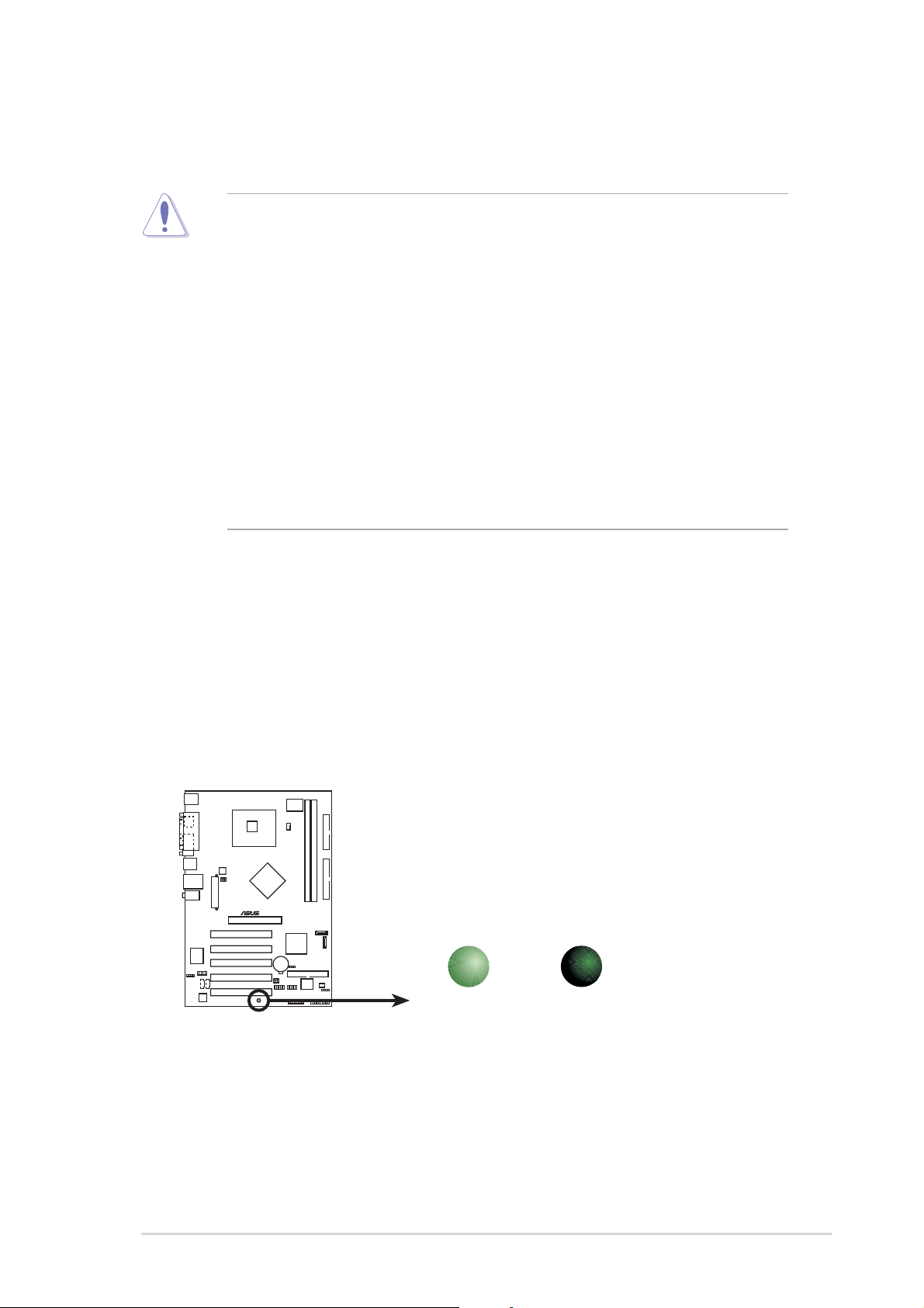
Onboard LEDOnboard LED
Onboard LED
Onboard LEDOnboard LED
The motherboard comes with a standby power LED that lights up to
indicate that the system is ON, in sleep mode, or in soft-off mode.
This is a reminder that you should shut down the system and unplug
the power cable before removing or plugging in any motherboard
component. The illustration below shows the location of the onboard
LED.
®
SB_PWR
P5P800S
P5P800S Onboard LED
ON
Standby
Power
OFF
Powered
Off
ASUS P5P800SASUS P5P800S
ASUS P5P800S
ASUS P5P800SASUS P5P800S
1-51-5
1-5
1-51-5
1.5 Motherboard overview
Before you install the motherboard, study the configuration of your chassis
to ensure that the motherboard fits into it.
Make sure to unplug the power cord before installing or removing the
motherboard. Failure to do so can cause you physical injury and damage
motherboard components.
1.5.11.5.1
1.5.1
1.5.11.5.1
Placement directionPlacement direction
Placement direction
Placement directionPlacement direction
When installing the motherboard, make sure that you place it into the
chassis in the correct orientation. The edge with external ports goes to the
rear part of the chassis as indicated in the image below.
1.5.21.5.2
1.5.2
1.5.21.5.2
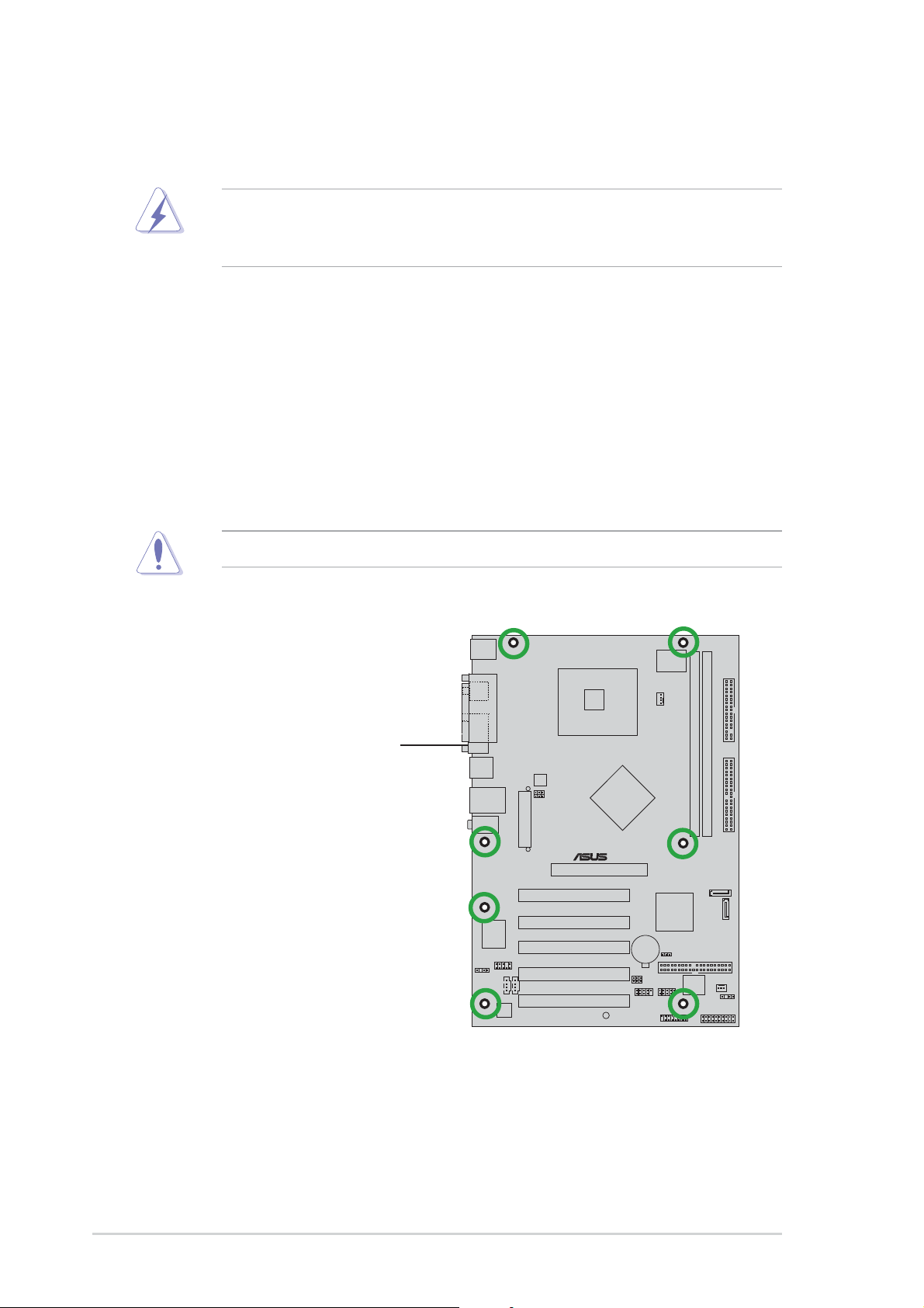
Screw holesScrew holes
Screw holes
Screw holesScrew holes
Place seven (7) screws into the holes indicated by circles to secure the
motherboard to the chassis.
Do not overtighten the screws! Doing so can damage the motherboard.
Place this side towardsPlace this side towards
Place this side towards
Place this side towardsPlace this side towards
the rear of the chassisthe rear of the chassis
the rear of the chassis
the rear of the chassisthe rear of the chassis
1-61-6
1-6
1-61-6
®
P5P800S
Chapter 1: Product introductionChapter 1: Product introduction
Chapter 1: Product introduction
Chapter 1: Product introductionChapter 1: Product introduction
1.5.31.5.3
1.5.3
1.5.31.5.3
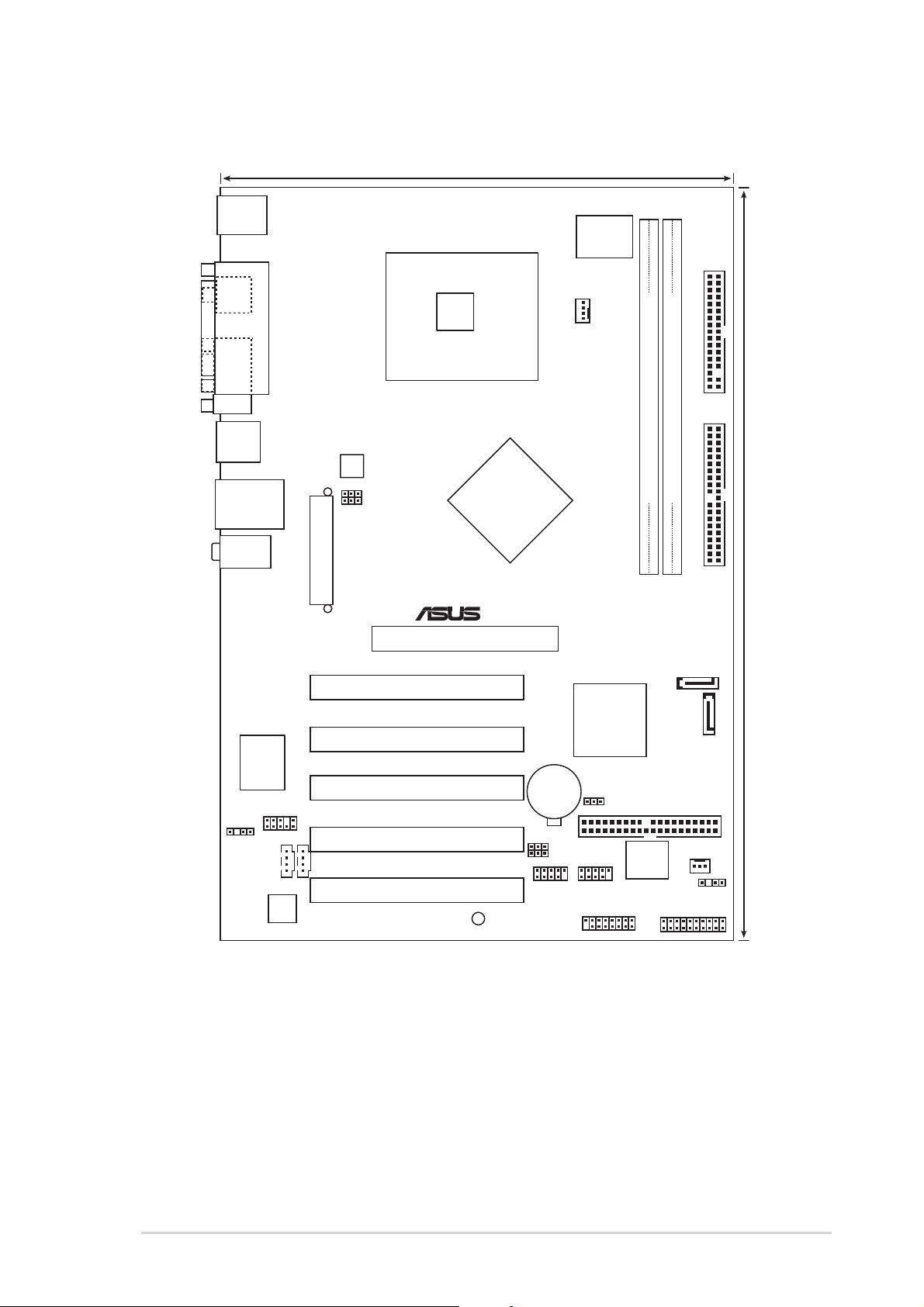
Motherboard layoutMotherboard layout
Motherboard layout
Motherboard layoutMotherboard layout
20.8cm( 8.2in)
PS/2KBMS
T: Mouse
B: Keyboard
SPDIF_O
PARALLEL PORT
LGA775
Super
I/O
CPU_FAN
COM1
USB12
LAN_USB34
Top:Line In
Center:Line Out
Below:Mic In
RTL8100C
FP_AUDIO
ATXPWR
ATX12V
USBPW12
USBPW34
PCI1
PCI2
PCI3
AGP
Intel
848P
®
CR2032 3V
Lithium Cell
CMOS Power
Intel
ICH5
CLRTC
FLOPPY
DDR DIMM2 (64 bit,184-pin module)
DDR DIMM1 (64 bit,184-pin module)
SEC_IDE
30.5cm (12.0in)
SATA2
SATA1
PRI_IDE
SPDIF_OUT
CD
AD1888
ASUS P5P800SASUS P5P800S
ASUS P5P800S
ASUS P5P800SASUS P5P800S
AUX
P5P800S
PCI4
PCI5
SB_PWR
USBPW78
USBPW56
USB56
USB78
GAME
3Mb
FWH
CHA_FAN
CHASSIS
PANEL
1-71-7
1-7
1-71-7
1.6 Central Processing Unit (CPU)
The motherboard comes with a surface mount LGA775 socket designed for
the Intel® Pentium® 4 processor in the 775-land package.
•
Your boxed Intel® Pentium® 4 LGA775 processor package should
come with installation instructions for the CPU, fan and heatsink
assembly. If the instructions in this section do not match the CPU
documentation, follow the latter.
• Upon purchase of the motherboard, make sure that the PnP cap is
on the socket and the socket pins are not bent. Contact your
retailer immediately if the PnP cap is missing, or if you see any
damage to the PnP cap/socket pins/motherboard components.
ASUS will shoulder the cost of repair only if the damage is shipment/
transit-related.
• Keep the cap after installing the motherboard. ASUS will process
Return Merchandise Authorization (RMA) requests only if the
motherboard comes with the cap on the LGA775 socket.
•
The product warranty does not cover damage to the socket pins
resulting from incorrect CPU installation/removal, or misplacement/
loss/incorrect removal of the PnP cap.
1.6.11.6.1
1.6.1
1.6.11.6.1
Installling the CPUInstallling the CPU
Installling the CPU
Installling the CPUInstallling the CPU
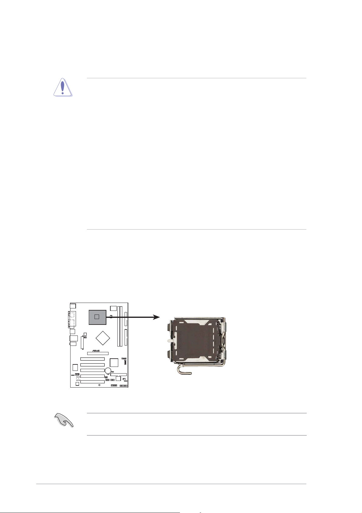
To install a CPU:
1. Locate the CPU socket on the motherboard.
®
P5P800S
P5P800S CPU Socket 775
Before installing the CPU, make sure that the socket box is facing
towards you and the load lever is on your left.
1-81-8
1-8
1-81-8
Chapter 1: Product introductionChapter 1: Product introduction
Chapter 1: Product introduction
Chapter 1: Product introductionChapter 1: Product introduction
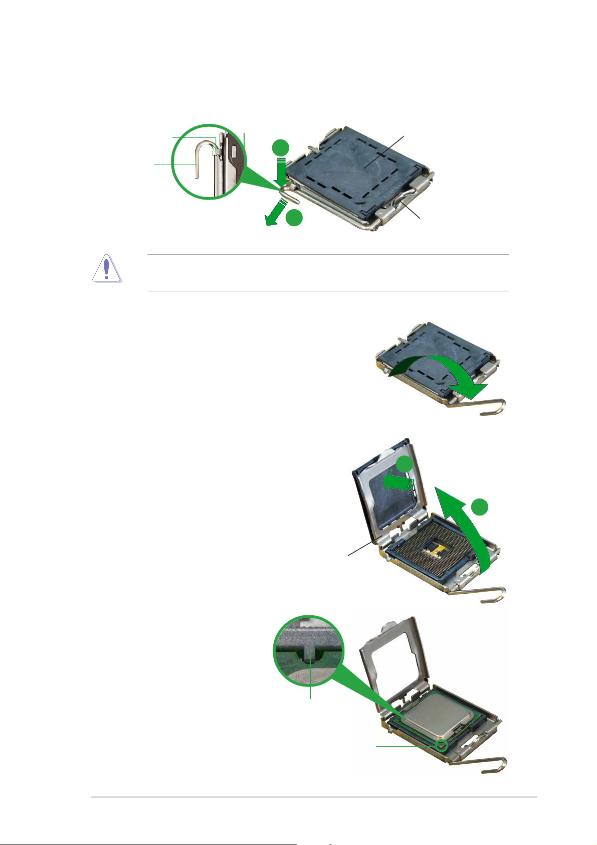
2. Press the load lever with your thumb (A) and move it to the left (B)
until it is released from the retention tab.
PnP CapPnP Cap
PnP Cap
Retention tabRetention tab
Retention tab
Retention tabRetention tab
PnP CapPnP Cap
A
Load leverLoad lever
Load lever
Load leverLoad lever
B
This side of the camThis side of the cam
This side of the cam
This side of the camThis side of the cam
box should face you.box should face you.
box should face you.
box should face you.box should face you.
To prevent damage to the socket pins, do not remove the PnP cap
unless you are installing a CPU.
3. Lift the load lever in the direction
of the arrow to a 135º angle.
4. Lift the load plate with your
thumb and forefinger to a 100º
angle (A), then push the PnP cap
from the load plate window to
remove (B).
5. Position the CPU over the
socket, making sure that
the gold triangle is on
the bottom-left corner of
the socket. The socket
alignment key should fit
Alignment keyAlignment key
Alignment key
Alignment keyAlignment key
into the CPU notch.
Load plateLoad plate
Load plate
Load plateLoad plate
B
A
ASUS P5P800SASUS P5P800S
ASUS P5P800S
ASUS P5P800SASUS P5P800S
Gold triangle markGold triangle mark
Gold triangle mark
Gold triangle markGold triangle mark
1-91-9
1-9
1-91-9
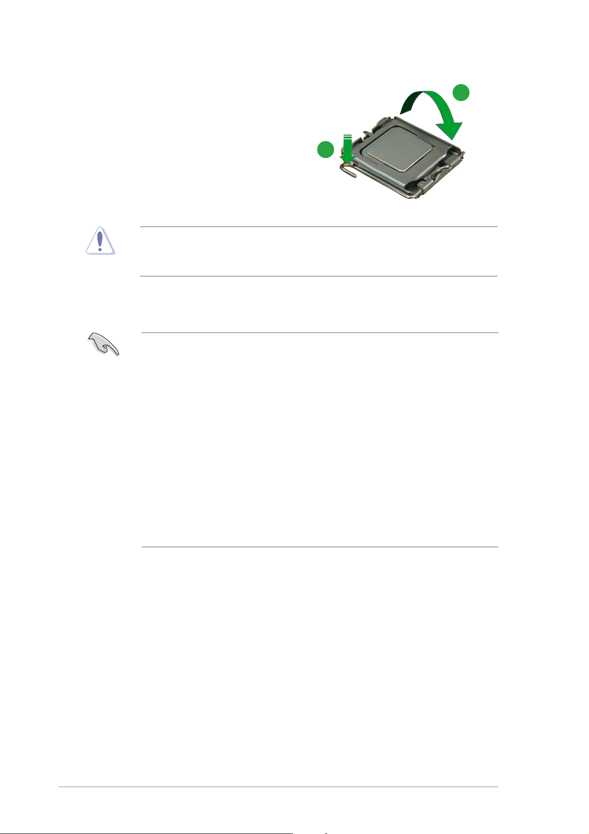
6. Close the load plate (A), then
push the load lever (B) until it
snaps into the retention tab.
The CPU fits in only one correct orientation. DO NOT force the CPU into
the socket to prevent bending the connectors on the socket and
damaging the CPU!
A
B
Notes on IntelNotes on Intel
Notes on Intel
Notes on IntelNotes on Intel
• This motherboard supports Intel® Pentium® 4 CPUs in the 775-land
• Hyper-Threading Technology is supported under Windows
• Installing Windows
• Make sure to enable the Hyper-Threading Technology item in BIOS
• For more information on Hyper-Threading Technology, visit
®
Hyper-Threading Technology Hyper-Threading Technology
Hyper-Threading Technology
Hyper-Threading Technology Hyper-Threading Technology
package with Hyper-Threading Technology.
®
XP/2003
Server and Linux 1.7.x (kernel) and later versions only. Under Linux,
use the Hyper-Threading compiler to compile the code. If you are
using any other operating systems, disable the Hyper-Threading
Technology item in the BIOS to ensure system stability and
performance.
®
XP Service Pack 1 or later is recommended.
before installing a supported operating system.
www.intel.com/info/hyperthreading.
To use the Hyper-Threading Technology on this motherboard:
®
1. Install an Intel
Pentium® 4 CPU in the 775-land package that supports
Hyper-Threading Technology.
2. Power up the system and enter the BIOS Setup (see Chapter 2: BIOS
setup). Under the Advanced Menu, make sure that the item
Hyper-Threading Technology is set to Enabled. The item appears only
if you installed a CPU that supports Hyper-Threading Technology.
3. Reboot the computer.
1-101-10
1-10
1-101-10
Chapter 1: Product introductionChapter 1: Product introduction
Chapter 1: Product introduction
Chapter 1: Product introductionChapter 1: Product introduction
1.6.21.6.2
1.6.2
1.6.21.6.2
Installling the CPU heatsink and fanInstallling the CPU heatsink and fan
Installling the CPU heatsink and fan
Installling the CPU heatsink and fanInstallling the CPU heatsink and fan
The Intel® Pentium® 4 LGA775 processor requires a specially designed
heatsink and fan assembly to ensure optimum thermal condition and
performance.
•
When you buy a boxed Intel® Pentium® 4 processor, the package
includes the CPU fan and heatsink assembly. If you buy a CPU
separately, make sure that you use only Intel®-certified
multi-directional heatsink and fan.
•
Your Intel® Pentium® 4 LGA775 heatsink and fan assembly comes in
a push-pin design and requires no tool to install.
•
If you purchased a separate CPU heatsink and fan assembly, make
sure that you have properly applied Thermal Interface Material to the
CPU heatsink or CPU before you install the heatsink and fan
assembly.
Make sure that you have installed the motherboard to the chassis before
you install the CPU fan and heatsink assembly.
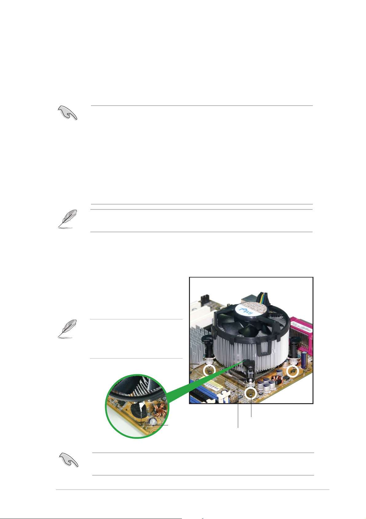
To install the CPU heatsink and fan:
1. Place the heatsink on top of the
installed CPU, making sure that
the four fasteners match the
holes on the motherboard.
Orient the heatsink and fan
assembly such that the CPU
fan cable is closest to the
CPU fan connector.
Narrow endNarrow end
Narrow end
Narrow endNarrow end
of the grooveof the groove
of the groove
of the grooveof the groove
Motherboard holeMotherboard hole
Motherboard hole
Motherboard holeMotherboard hole
FastenerFastener
Fastener
FastenerFastener
Make sure to orient each fastener with the narrow end of the groove
pointing outward. (The photo shows the groove shaded for emphasis.)
ASUS P5P800SASUS P5P800S
ASUS P5P800S
ASUS P5P800SASUS P5P800S
1-111-11
1-11
1-111-11
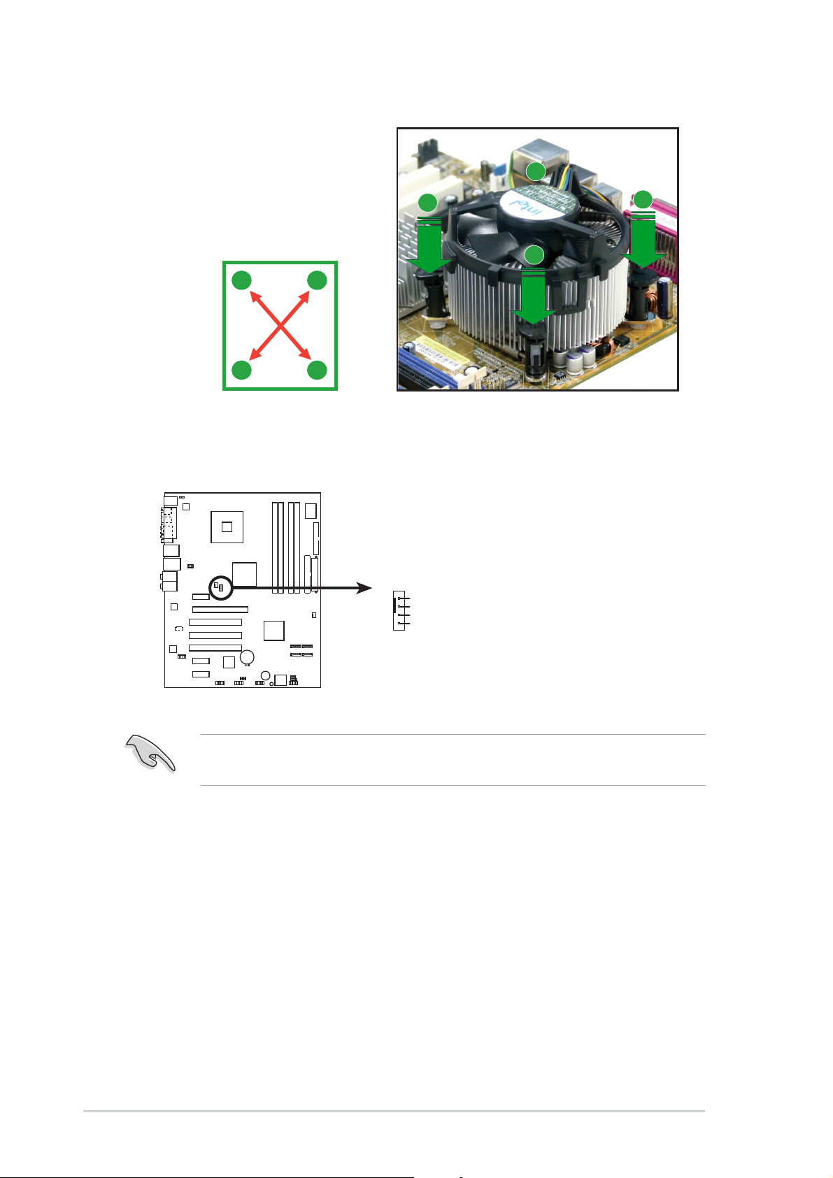
2. Push down two fasteners at
a time in a diagonal
sequence to secure the
heatsink and fan assembly in
place.
B
A
B
A
A
B
B
A
3. Connect the CPU fan cable to the connector on the motherboard
labeled CPU_FAN.
CPU_FAN
GND
CPU FAN PWR
CPU FAN IN
P5GD1
CPU FAN PWM
P5GD1 CPU_Fan connector
Do not forget to connect the CPU fan connector! Hardware monitoring
errors can occur if you fail to plug this connector.
1-121-12
1-12
1-121-12
Chapter 1: Product introductionChapter 1: Product introduction
Chapter 1: Product introduction
Chapter 1: Product introductionChapter 1: Product introduction
1.6.31.6.3
1.6.3
1.6.31.6.3
Uninstalling the CPU heatsink and fanUninstalling the CPU heatsink and fan
Uninstalling the CPU heatsink and fan
Uninstalling the CPU heatsink and fanUninstalling the CPU heatsink and fan
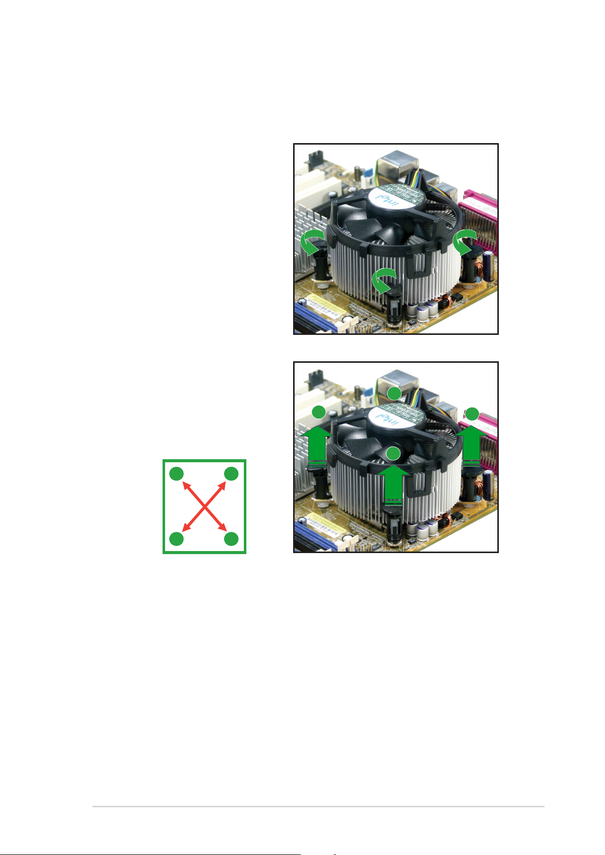
To uninstall the CPU heatsink and fan:
1. Disconnect the CPU fan
cable from the connector on
the motherboard.
2. Rotate each fastener
counterclockwise.
3. Pull up two fasteners at a
time in a diagonal sequence
to disengage the heatsink
and fan assembly from the
A
motherboard.
B
A
B
A
B
B
A
ASUS P5P800SASUS P5P800S
ASUS P5P800S
ASUS P5P800SASUS P5P800S
1-131-13
1-13
1-131-13
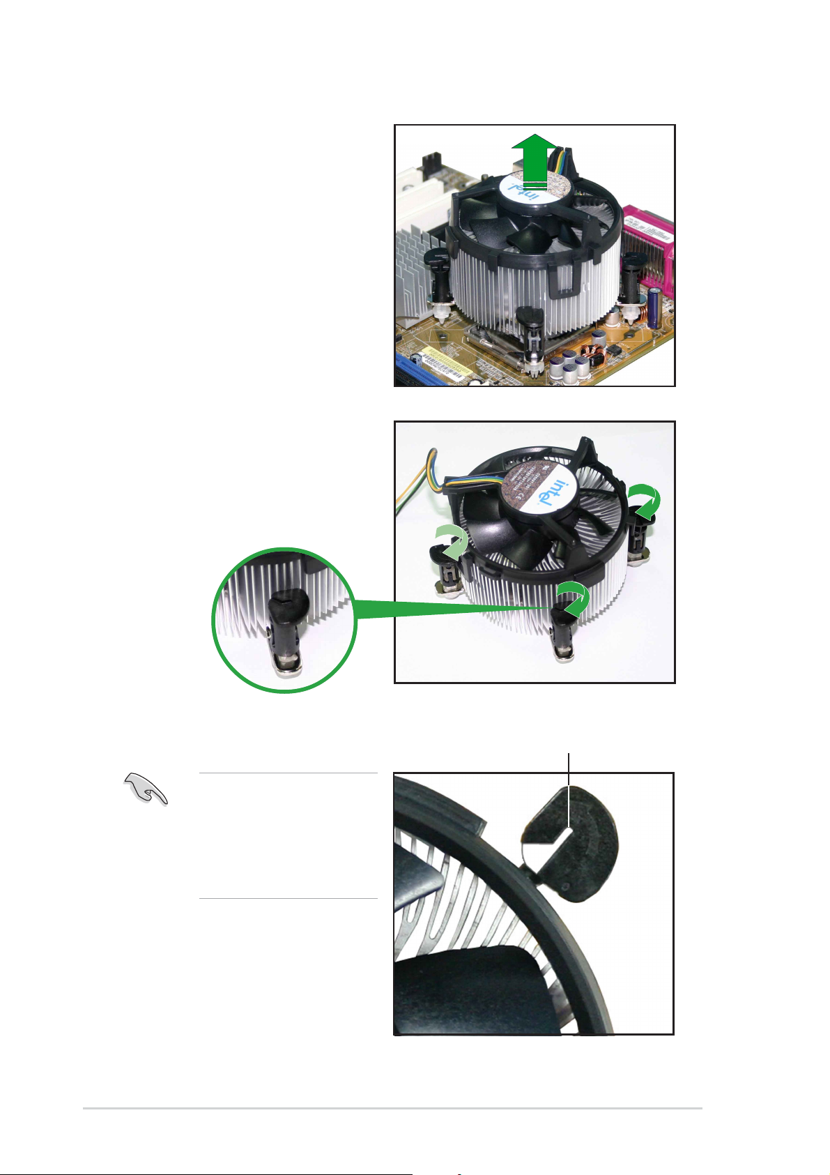
4. Carefully remove the
heatsink and fan assembly
from the motherboard.
5. Rotate each fastener
clockwise to ensure correct
orientation when
reinstalling.
1-141-14
1-14
1-141-14
The narrow end of the
groove should point
outward after resetting.
(The photo shows the
groove shaded for
emphasis.)
Narrow end of the grooveNarrow end of the groove
Narrow end of the groove
Narrow end of the grooveNarrow end of the groove
Chapter 1: Product introductionChapter 1: Product introduction
Chapter 1: Product introduction
Chapter 1: Product introductionChapter 1: Product introduction
1.7 System memory
1.7.11.7.1
1.7.1
1.7.11.7.1
OverviewOverview
Overview
OverviewOverview
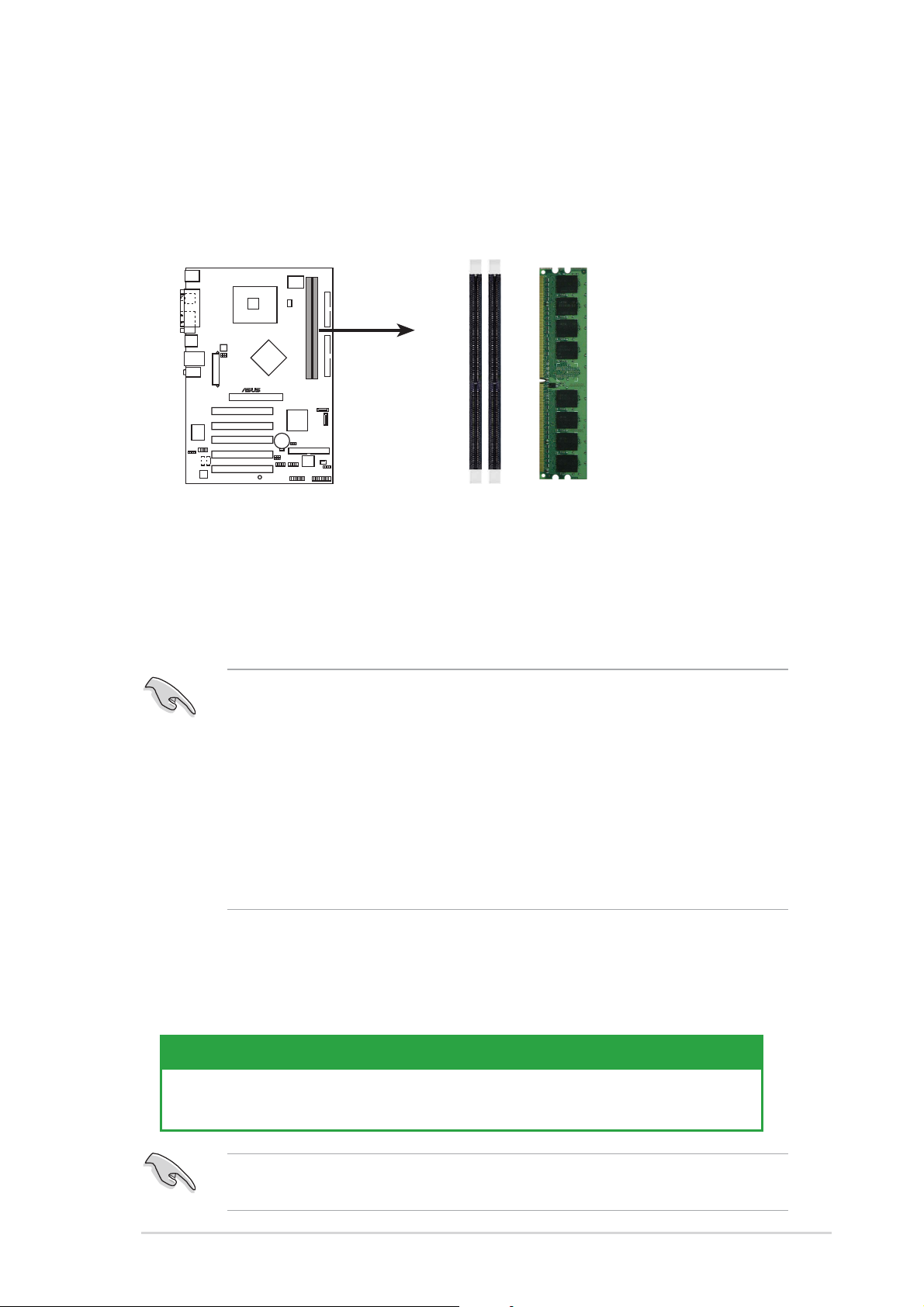
The motherboard comes with two 184-pin Double Data Rate (DDR) Dual
Inline Memory Modules (DIMM) sockets. The following figure illustrates the
location of the sockets:
®
P5P800S
P5P800S 184-pin DDR DIMM sockets
1.7.21.7.2
1.7.2
1.7.21.7.2
Memory ConfigurationsMemory Configurations
Memory Configurations
Memory ConfigurationsMemory Configurations
DIMM1
DIMM2
You may install 128 MB, 256 MB, 512 MB and 1 GB unbuffered non-ECC
DDR DIMMs into the DIMM sockets using the memory configurations in this
section.
1. For optimum compatibility, it is recommended that you obtain
memory modules from the same vendor. See the DDR400 Qualified
Vendor List (QVL) on page 1-16.
2. Make sure that the memory frequency matches the CPU FSB (Front
Side Bus). Refer to the
synchronizationsynchronization
synchronization table below.
synchronizationsynchronization
3. Always install DIMMs with the same CAS Latency.
4. Double-sided DDR DIMMs with
are not supported due to chipset limitation.
Memory frequency/CPU FSB synchronizationMemory frequency/CPU FSB synchronization
Memory frequency/CPU FSB synchronization
Memory frequency/CPU FSB synchronizationMemory frequency/CPU FSB synchronization
Memory frequency/CPU FSBMemory frequency/CPU FSB
Memory frequency/CPU FSB
Memory frequency/CPU FSBMemory frequency/CPU FSB
x16x16
x16 (data bus=16bit) memory chips
x16x16
This motherboard supports different memory frequencies depending on the
CPU FSB (Front Side Bus) and the type of DDR DIMM.
CPU FSBCPU FSB
CPU FSB
CPU FSBCPU FSB
800 MHz PC3200/PC2700/PC2100 400/320*/266 MHz
533 MHz PC2700/PC2100 333/266 MHz
DDR DIMM TypeDDR DIMM Type
DDR DIMM Type
DDR DIMM TypeDDR DIMM Type
Memory FrequencyMemory Frequency
Memory Frequency
Memory FrequencyMemory Frequency
*When using 800 MHz FSB CPU, PC2700 DDR DIMMs run only at 320MHz
(not 333MHz) due to chipset limitation.
ASUS P5P800SASUS P5P800S
ASUS P5P800S
ASUS P5P800SASUS P5P800S
1-151-15
1-15
1-151-15
 Loading...