

Page 1

P5N-VM WS
Motherboard
Page 2

E4201
First Edition
September 2008
Copyright © 2008 ASUSTeK COMPUTER INC. All Rights Reserved.
No part of this manual, including the products and software described in it, may be reproduced,
transmitted, transcribed, stored in a retrieval system, or translated into any language in any form or by any
means, except documentation kept by the purchaser for backup purposes, without the express written
permission of ASUSTeK COMPUTER INC. (“ASUS”).
Product warranty or service will not be extended if: (1) the product is repaired, modied or altered, unless
such repair, modication of alteration is authorized in writing by ASUS; or (2) the serial number of the
product is defaced or missing.
ASUS PROVIDES THIS MANUAL “AS IS” WITHOUT WARRANTY OF ANY KIND, EITHER EXPRESS
OR IMPLIED, INCLUDING BUT NOT LIMITED TO THE IMPLIED WARRANTIES OR CONDITIONS OF
MERCHANTABILITY OR FITNESS FOR A PARTICULAR PURPOSE. IN NO EVENT SHALL ASUS, ITS
DIRECTORS, OFFICERS, EMPLOYEES OR AGENTS BE LIABLE FOR ANY INDIRECT, SPECIAL,
INCIDENTAL, OR CONSEQUENTIAL DAMAGES (INCLUDING DAMAGES FOR LOSS OF PROFITS,
LOSS OF BUSINESS, LOSS OF USE OR DATA, INTERRUPTION OF BUSINESS AND THE LIKE),
EVEN IF ASUS HAS BEEN ADVISED OF THE POSSIBILITY OF SUCH DAMAGES ARISING FROM ANY
DEFECT OR ERROR IN THIS MANUAL OR PRODUCT.
SPECIFICATIONS AND INFORMATION CONTAINED IN THIS MANUAL ARE FURNISHED FOR
INFORMATIONAL USE ONLY, AND ARE SUBJECT TO CHANGE AT ANY TIME WITHOUT NOTICE,
AND SHOULD NOT BE CONSTRUED AS A COMMITMENT BY ASUS. ASUS ASSUMES NO
RESPONSIBILITY OR LIABILITY FOR ANY ERRORS OR INACCURACIES THAT MAY APPEAR IN THIS
MANUAL, INCLUDING THE PRODUCTS AND SOFTWARE DESCRIBED IN IT.
Products and corporate names appearing in this manual may or may not be registered trademarks or
copyrights of their respective companies, and are used only for identication or explanation and to the
owners’ benet, without intent to infringe.
ii
Page 3

Contents
Contents ...................................................................................................... iii
Notices ........................................................................................................ vii
Safety information .................................................................................... viii
About this guide ......................................................................................... ix
P5N-VM WS specications ....................................................................... xi
Chapter 1: Product introduction
1.1 Welcome! ...................................................................................... 1-1
1.2 Package contents ......................................................................... 1-1
1.3 Special features ............................................................................ 1-2
1.3.1 Product highlights ........................................................... 1-2
1.3.2 ASUS special features ................................................... 1-3
Chapter 2: Hardware information
2.1 Before you proceed ..................................................................... 2-1
2.2 Motherboard overview ................................................................. 2-2
2.2.1 Motherboard layout ......................................................... 2-2
2.2.2 Layout contents ............................................................... 2-3
2.2.3 Placement direction ........................................................ 2-4
2.2.4 Screw holes .................................................................... 2-4
2.3 Central Processing Unit (CPU) ................................................... 2-5
2.3.1 Installing the CPU ........................................................... 2-6
2.3.2 Installing the CPU heatsink and fan ................................ 2-9
2.3.3 Uninstalling the CPU heatsink and fan ......................... 2-10
2.4 System memory ......................................................................... 2-11
2.4.1 Overview ........................................................................2-11
2.4.2 Memory congurations .................................................. 2-12
2.4.3 Installing a DIMM .......................................................... 2-16
2.4.4 Removing a DIMM ........................................................ 2-16
2.5 Expansion slots .......................................................................... 2-17
2.5.1 Installing an expansion card ......................................... 2-17
2.5.2 Conguring an expansion card ..................................... 2-17
2.5.3 Interrupt assignments ................................................... 2-18
2.5.4 PCI Express 2.0 x16 slot ............................................... 2-19
2.5.5 PCI Express x4 slot ....................................................... 2-19
2.5.6 PCI Express x1 slot ....................................................... 2-19
iii
Page 4

Contents
2.5.7 PCI slots ........................................................................ 2-19
2.6 Jumper ........................................................................................ 2-20
2.7 Connectors ................................................................................. 2-21
2.7.1 Rear panel connectors .................................................. 2-21
2.7.2 Internal connectors ....................................................... 2-23
2.8 Starting up for the rst time ...................................................... 2-30
2.9 Turning off the computer ........................................................... 2-31
2.9.1 Using the OS shut down function .................................. 2-31
2.9.2 Using the dual function power switch ............................ 2-31
Chapter 3: BIOS setup
3.1 Managing and updating your BIOS ............................................ 3-1
3.1.1 ASUS Update utility ........................................................ 3-1
3.1.2 ASUS EZ Flash 2 utility ................................................... 3-4
3.1.3 Creating a bootable oppy disk ....................................... 3-5
3.1.4 AFUDOS utility ................................................................ 3-6
3.1.5 ASUS CrashFree BIOS 3 utility ...................................... 3-8
3.2 BIOS setup program .................................................................... 3-9
3.2.1 BIOS menu screen ........................................................ 3-10
3.2.2 Menu bar ....................................................................... 3-10
3.2.3 Navigation keys ............................................................. 3-10
3.2.4 Menu items ....................................................................3-11
3.2.5 Sub-menu items .............................................................3-11
3.2.6 Conguration elds ........................................................3-11
3.2.7 Pop-up window ..............................................................3-11
3.2.8 Scroll bar ........................................................................3-11
3.2.9 General help ..................................................................3-11
3.3 Main menu .................................................................................. 3-12
3.3.1 System Time ................................................................. 3-12
3.3.2 System Date ................................................................. 3-12
3.3.3 Language ...................................................................... 3-12
3.3.4 SATA 1–4 .........................................................................................3-13
3.3.5 IDE Conguration .......................................................... 3-14
3.3.6 System Information ....................................................... 3-16
3.4 Advanced menu ......................................................................... 3-17
3.4.1 CPU Conguration ........................................................ 3-17
iv
Page 5

Contents
3.4.2 Chipset .......................................................................... 3-19
3.4.3 OnBoard Devices Conguration ................................... 3-21
3.4.4 USB Conguration ........................................................ 3-22
3.5 Power menu ................................................................................ 3-23
3.5.1 Suspend Mode .............................................................. 3-23
3.5.2 Repost Video on S3 Resume ........................................ 3-23
3.5.3 ACPI 2.0 Support .......................................................... 3-23
3.5.4 ACPI APIC Support ....................................................... 3-23
3.5.5 APM Conguration ........................................................ 3-24
3.5.6 Hardware Monitor ......................................................... 3-25
3.6 Boot menu .................................................................................. 3-26
3.6.1 Boot Device Priority ...................................................... 3-26
3.6.2 Boot Settings Conguration .......................................... 3-27
3.6.3 Security ......................................................................... 3-28
3.7 Tools menu ................................................................................. 3-30
3.7.1 ASUS EZ Flash 2 .......................................................... 3-30
3.7.2 Ai Net 2 ......................................................................... 3-31
3.8 Exit menu .................................................................................... 3-32
Chapter 4: Software support
4.1 Installing an operating system ................................................... 4-1
4.2 Support DVD information ............................................................ 4-1
4.2.1 Running the support DVD ............................................... 4-1
4.2.2 Drivers menu ................................................................... 4-2
4.2.3 Utilities menu .................................................................. 4-3
4.2.4 Make Disk menu ............................................................. 4-4
4.2.5 Manual menu .................................................................. 4-5
4.2.6 ASUS Contact information .............................................. 4-5
4.2.7 Other information ............................................................ 4-6
4.3 Software information ................................................................... 4-8
4.3.1 ASUS MyLogo2™ ........................................................... 4-8
4.3.2 ASUS PC Probe II ......................................................... 4-10
4.3.3 SoundMAX® High Denition Audio utility ....................... 4-16
4.4 RAID congurations .................................................................. 4-23
4.4.1 RAID denitions ............................................................ 4-23
4.4.2 NVIDIA® RAID congurations........................................ 4-24
v
Page 6

Contents
4.5 RAID driver installation ............................................................. 4-31
4.5.1 Creating a RAID driver disk without entering the OS .... 4-31
4.5.2 Creating a RAID driver disk in Windows®...................... 4-31
4.5.3 Installing the RAID controller driver .............................. 4-32
vi
Page 7

Notices
Federal Communications Commission Statement
This device complies with Part 15 of the FCC Rules. Operation is subject to the
following two conditions:
•
This device may not cause harmful interference, and
•
This device must accept any interference received including interference that
may cause undesired operation.
This equipment has been tested and found to comply with the limits for a
Class B digital device, pursuant to Part 15 of the FCC Rules. These limits are
designed to provide reasonable protection against harmful interference in a
residential installation. This equipment generates, uses and can radiate radio
frequency energy and, if not installed and used in accordance with manufacturer’s
instructions, may cause harmful interference to radio communications. However,
there is no guarantee that interference will not occur in a particular installation. If
this equipment does cause harmful interference to radio or television reception,
which can be determined by turning the equipment off and on, the user is
encouraged to try to correct the interference by one or more of the following
measures:
•
Reorient or relocate the receiving antenna.
•
Increase the separation between the equipment and receiver.
•
Connect the equipment to an outlet on a circuit different from that to which the
receiver is connected.
•
Consult the dealer or an experienced radio/TV technician for help.
The use of shielded cables for connection of the monitor to the graphics card is
required to assure compliance with FCC regulations. Changes or modications
to this unit not expressly approved by the party responsible for compliance
could void the user’s authority to operate this equipment.
Canadian Department of Communications Statement
This digital apparatus does not exceed the Class B limits for radio noise emissions
from digital apparatus set out in the Radio Interference Regulations of the
Canadian Department of Communications.
This class B digital apparatus complies with Canadian ICES-003.
vii
Page 8

Safety information
Electrical safety
•
To prevent electrical shock hazard, disconnect the power cable from the
electrical outlet before relocating the system.
•
When adding or removing devices to or from the system, ensure that the power
cables for the devices are unplugged before the signal cables are connected. If
possible, disconnect all power cables from the existing system before you add
a device.
•
Before connecting or removing signal cables from the motherboard, ensure
that all power cables are unplugged.
•
Seek professional assistance before using an adpater or extension cord.
These devices could interrupt the grounding circuit.
•
Make sure that your power supply is set to the correct voltage in your area. If
you are not sure about the voltage of the electrical outlet you are using, contact
your local power company.
•
If the power supply is broken, do not try to x it by yourself. Contact a qualied
service technician or your retailer.
Operation safety
•
Before installing the motherboard and adding devices on it, carefully read all
the manuals that came with the package.
•
Before using the product, make sure all cables are correctly connected and the
power cables are not damaged. If you detect any damage, contact your dealer
immediately.
•
To avoid short circuits, keep paper clips, screws, and staples away from
connectors, slots, sockets and circuitry.
•
Avoid dust, humidity, and temperature extremes. Do not place the product in
any area where it may become wet.
•
Place the product on a stable surface.
•
If you encounter technical problems with the product, contact a qualied
service technician or your retailer.
viii
This symbol of the crossed out wheeled bin indicates that the product (electrical,
electronic equipment and mercury-containing button cell battery) should not
be placed in municipal waste. Check local regulations for disposal of electronic
products.
Page 9

About this guide
This user guide contains the information you need when installing and conguring
the motherboard.
How this guide is organized
This guide contains the following parts:
• Chapter 1: Product introduction
This chapter describes the features of the motherboard and the new
technology it supports.
• Chapter 2: Hardware information
This chapter lists the hardware setup procedures that you have to perform
when installing system components. It includes description of the jumpers
and connectors on the motherboard.
• Chapter 3: BIOS setup
This chapter tells how to change system settings through the BIOS Setup
menus. Detailed descriptions of the BIOS parameters are also provided.
• Chapter 4: Software support
This chapter describes the contents of the support DVD that comes with the
motherboard package.
Where to nd more information
Refer to the following sources for additional information and for product and
software updates.
1. ASUS websites
The ASUS website provides updated information on ASUS hardware and
software products. Refer to the ASUS contact information.
2. Optional documentation
Your product package may include optional documentation, such as warranty
yers, that may have been added by your dealer. These documents are not
part of the standard package.
ix
Page 10

Conventions used in this guide
To make sure that you perform certain tasks properly, take note of the following
symbols used throughout this manual.
DANGER/WARNING: Information to prevent injury to yourself
when trying to complete a task.
CAUTION: Information to prevent damage to the components
when trying to complete a task.
IMPORTANT: Instructions that you MUST follow to complete a
task.
NOTE: Tips and additional information to help you complete a
task.
Typography
Bold text Indicates a menu or an item to select.
Italics
Used to emphasize a word or a phrase.
<Key> Keys enclosed in the less-than and greater-than sign
means that you must press the enclosed key.
Example: <Enter> means that you must press the
Enter or Return key.
<Key1>+<Key2>+<Key3> If you must press two or more keys simultaneously, the
key names are connected with a plus sign (+).
Example: <Ctrl>+<Alt>+<D>
Command Means that you must type the command exactly as
shown.
Example: At the DOS prompt, type the command line:
afudos /iP5NVMWS.ROM
x
Page 11

P5N-VM WS specications
CPU LGA775 socket for Intel® Core™ 2 Extreme /
Chipset NVIDIA® Quadro FX470
System bus 1333 / 1066 / 800 MHz with EM64T
Memory Dual-channel memory architecture
Expansion slots 1 x PCIe 2.0 x16 slot (x16 link)
VGA Integrated Quadro FX470
Storage NVIDIA® Quadro FX470
LAN 2 x Realtek® RTL8111C Gigabit LAN controllers
High Denition audio ADI® 1988B 8-channel High-Denition Audio CODEC
USB 12 x USB 2.0 ports (6 ports at mid-board, 6 ports at back
Core™ 2 Quad / Core™ 2 Duo / Pentium® dual-core /
Celeron® dual-core / Celeron® processors
Compatible with Intel® 05B/05A/06 processors
Intel® 45nm multi-core CPU support
* Refer to www.asus.com for Intel® CPU support list
- 4 x 240-pin DIMM sockets support non-ECC
unbuffered DDR2 800 / 667 MHz memory modules
- Supports up to 8 GB system memory
1 x PCIe x4 slot (x1 link) for SAS,
1 x PCIe x1 slot (x1 link)
1 x PCI 32-bit / 33MHz slot
Quadro NVIEW support for Quad Display
OpenGL 2.1 and DX10 support
- 6 x Serial ATA 3.0 Gb/s ports
- NVIDIA® MediaShield™ RAID supports RAID 0, 1,™ RAID supports RAID 0, 1, RAID supports RAID 0, 1,RAID 0, 1,
0+1, 5 and JBOD conguration across SATA drives
Optional SAS Controller add-on card
Optional 1: SASsaby 1064E PCIe 4-port SAS card
- Supports LSI® Integrated RAID 0, 1, and 1E
Optional 2: SASsaby M PCIe 4-port SAS card
- Supports Hardware RAID 0, 1, 10 and 5
- Supports teaming function
- Supports Jack-Sensing, Multi-Streaming, and Jack-Supports Jack-Sensing, Multi-Streaming, and Jack Retasking Technology
- Coaxial / Optical S/PDIF out ports at back I/O
panel)
(continued on the next page)
xi
Page 12

P5N-VM WS specications
ASUS Unique Features ASUS Workstation Features:
Other Features ASUS MyLogo 2
Internal connectors 3 x USB connectors support six additional USB ports
Rear panel connectors 1 x PS/2 keyboard / mouse combo port
BIOS features 8 Mb Flash ROM, AMI BIOS, PnP, DMI 2.0, WfM2.0,
Manageability WOL by PME, WOR by PME, PXE, AI NET 2, Chassis
Support DVD contents Drivers
Form factor uATX form factor: 9.6 in x 9.6 in
*Specications are subject to change without notice.
- ASUS SASsaby cards support
ASUS Quiet Thermal Solution:
- ASUS Fanless Design: Cool Thermal Solution
ASUS EZ DIY:
- ASUS CrashFree BIOS 3
- ASUS EZ Flash 2
- ASUS Q-Shield
Multi-language BIOS
6 x Serial ATA connectors
1 x CPU fan connector with PWM control
4 x Chassis fan connectors
1 x TPM connector
1 x Chassis intrusion connector
1 x Front panel audio connector
1 x CD audio in connector
1 x 20-pin ATX power connector
1 x 4-pin ATX +12 V power connector
1 x 24-pin panel connector
2 x LAN (RJ-45) ports
1 x S/PDIF Out port (Coaxial + Optical)
6 x USB 2.0/1.1 ports
8-channel audio ports
2 x DVI-I ports
- Upper: Single Link with max. resolution up to
1920 x 1200
- Lower: Dual Link with max. resolution up to
2560 x 1600
SMBIOS 2.3, ACPI 2.0a
Intrusion, BIOS ash utility under DOS
ASUS PC Probe II
Anti-virus software
Adobe Acrobat Reader 8
Microsoft Direct X ver 9.0C
xii
Page 13

This chapter describes the features of
the motherboard and the new technology
it supports.
Chapter 1: Product
introduction
1
Page 14

Chapter summary
1
1.1 Welcome! ...................................................................................... 1-1
1.2 Package contents ......................................................................... 1-1
1.3 Special features ............................................................................ 1-2
ASUS P5N-VM WS
Page 15

1.1 Welcome!
Thank you for buying an ASUS® P5N-VM WS motherboard!
The motherboard delivers a host of new features and latest technologies, making it
another standout in the long line of ASUS quality motherboards!
Before you start installing the motherboard, and hardware devices on it, check the
items in your package with the list below.
1.2 Package contents
Check your motherboard package for the following items.
Motherboard ASUS P5N-VM WS
Accessories 1 x ASUS Q-Shidle (I/O shield)
Application DVD ASUS motherboard support DVD
Documentation User guide
If any of the above items is damaged or missing, contact your retailer.
ASUS P5N-VM WS 1-1
Page 16

1.3 Special features
1.3.1 Product highlights
Green ASUS
This motherboard and its packaging comply with the European Union’s Restriction
on the use of Hazardous Substances (RoHS). This is in line with the ASUS vision
of creating environment-friendly and recyclable products/packaging to safeguard
consumers’ health while minimizing the impact on the environment.
Intel® Core™2 Extreme / Core™ 2 Quad /
Core™2 Duo Processor Support
This motherboard supports the latest Intel® Core™ 2 Extreme / Core™ 2 Quad /
Core™ 2 Duo processors in the LGA775 package. It is excellent for multi-tasking,
multi-media and enthusiastic gamers with 1333 / 1066 / 800 MHz FSB. The Intel®
Core™ 2 series processor is one of the most powerful CPUs in the world. This
motherboard also supports Intel® CPUs in the new 45nm manufacturing process.
NVIDIA® Quadro FX470 chipset
It is the rst integrated Quadro chipset used to build on Intel LGA775 motherboard.
It supports Intel® CPU Front Side Bus interface with Hyper-Threading up to
1333MT/s (333 MHz bus clock), 128-bit dual-channel DDR2-800 (2 DIMMs per
channel), and dual-DVI-I interface with integrated HDCP key. AHCI SATA controller
is integrated with support up to six drives at 1.5Gbps or 3.0 Gbps speeds, which
users can congure RAID0, 1, 0+1, 5 and JBOD in NVIDIA® MediaShield™ RAID.
PCIe 2.0
This motherboard supports the latest PCIe 2.0 device for twice the current speed
and bandwidth. This enhances system performance while still providing backward
compatibility to PCIe 1.0 devices. See page page 2-19 for details.
S/PDIF digital sound ready
This motherboard provides convenient connectivity to external home theater audio
systems via coaxial and optical S/PDIF-out (SONY-PHILIPS Digital Interface)
jacks. It allows to transfer digital audio without converting to analog format and
keeps the best signal quality. See page 2-21 and 2-22 for details.
1-2 Chapter 1: Product Introduction
Page 17
Dual Gigabit LAN solution
The integrated dual Gigabit LAN design allows a PC to serve as a network
gateway for managing trafc between two separate networks. This capability
ensures rapid transfer of data from WAN to LAN without any added arbitration or
latency. See page 2-21 for details.
High Denition Audio
Enjoy high-end sound quality on your PC! The onboard 8-channel HD audio (High
Denition Audio, previously codenamed Azalia) CODEC enables high-quality
192KHz/24-bit audio output, jack-sensing feature, retasking functions and multi-
streaming technology that simultaneously sends different audio streams to different
destinations. You can now talk to your partners on the headphone while playing
multi-channel network games. See page 2-22 for details.
1.3.2 ASUS special features
ASUS Workstation Features
ASUS Workstation features provide complete support to system maintenance and
storage technology.
ASUS SASsaby cards support
This motherboard is fully compatible with ASUS SASsaby cards (optional).
Faster, safer and more stable, SAS will provide users with a better choice for
storage expansion and upgrade needs.
ASUS EZ DIY
ASUS EZ DIY feature collection provides you easy ways to install computer
components, update the BIOS or back up your favorite settings.
ASUS CrashFree BIOS 3
The ASUS CrashFree BIOS 3 allows users to restore corrupted BIOS data
from a USB ash disk containing the BIOS le. See page 3-8 for details.
ASUS P5N-VM WS 1-3
Page 18
ASUS EZ Flash 2
EZ Flash 2 is a user-friendly BIOS update utility. Simply press the predened
hotkey to launch the utility and update the BIOS without entering the OS.
Update your BIOS easily without preparing a bootable diskette or using an
OS-based ash utility. See page 3-4 for details.
ASUS Q-Shield
The specially designed ASUS Q-Shield provides conductivity to best protect
your motherboard against static electricity damage and shields it against
Electronic Magnetic Interference (EMI). Without the usual "ngers" present,
this new design is convenient and safe to install.
ASUS MyLogo2™
This feature allows you to convert your favorite photo into a 256-color boot
logo for a more colorful and vivid image on your screen. See page 4-8 for
details.
ASUS Multi-language BIOS
The multi-language BIOS allows you to select the language of your choice from the
available options. The localized BIOS setup menu helps you congure your system
easier and faster. See page 3-12 for details.
1-4 Chapter 1: Product Introduction
Page 19

This chapter lists the hardware setup
procedures that you have to perform
when installing system components. It
includes description of the jumpers and
connectors on the motherboard.
Hardware
information
2
Page 20

Chapter summary
2
2.1 Before you proceed ..................................................................... 2-1
2.2 Motherboard overview ................................................................. 2-2
2.3 Central Processing Unit (CPU) ................................................... 2-5
2.4 System memory ......................................................................... 2-11
2.5 Expansion slots .......................................................................... 2-17
2.6 Jumper ........................................................................................ 2-20
2.7 Connectors ................................................................................. 2-21
2.8 Starting up for the rst time ...................................................... 2-30
2.9 Turning off the computer ........................................................... 2-31
ASUS P5N-VM WS
Page 21
2.1 Before you proceed
Take note of the following precautions before you install motherboard components
or change any motherboard settings.
• Unplug the power cord from the wall socket before touching any
component.
• Use a grounded wrist strap or touch a safely grounded object or a metal
object, such as the power supply case, before handling components to
avoid damaging them due to static electricity.
• Hold components by the edges to avoid touching the ICs on them.
• Whenever you uninstall any component, place it on a grounded antistatic
pad or in the bag that came with the component.
• Before you install or remove any component, ensure that the ATX power
supply is switched off or the power cord is detached from the power
supply. Failure to do so may cause severe damage to the motherboard,
peripherals, and/or components.
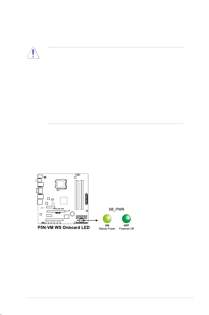
Onboard LED
The motherboard comes with a standby power LED that lights up to indicate that
the system is ON, in sleep mode, or in soft-off mode. This is a reminder that you
should shut down the system and unplug the power cable before removing or
plugging in any motherboard component. The illustration below shows the location
of the onboard LED.
ASUS P5N-VM WS 2-1
Page 22
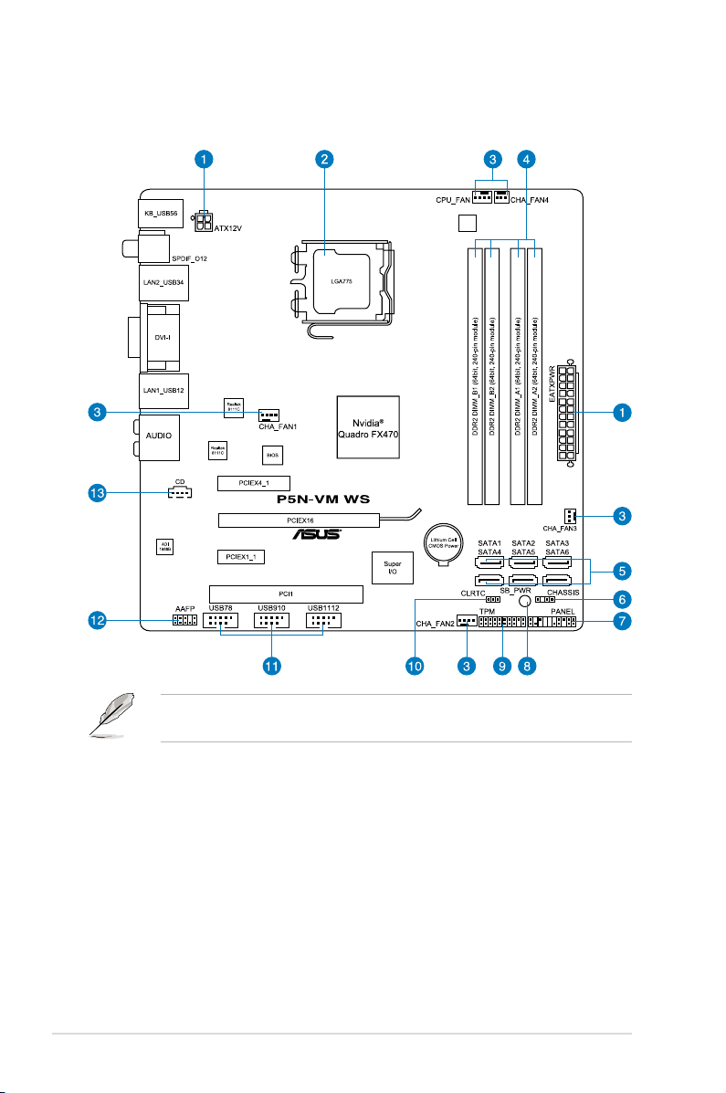
2.2 Motherboard overview
2.2.1 Motherboard layout
Refer to
2.7 Connectors
internal connectors.
2-2 Chapter 2: Hardware information
for more information about rear panel connectors and
Page 23

2.2.2 Layout contents
Internal connectors Page
1. ATX power connectors (24-pin EATXPWR, 4-pin ATX12V) 2-28
2. LGA775 CPU Socket 2-6
3. CPU and chassis fan connectors (4-pin CPU_FAN, 4-pin
CHA_FAN1-2, 3-pin CHA_FAN3-4)
4. DDR2 DIMM slots 2-11
5. NVIDIA Quadro FX470 Serial ATA connectors
(7-pin SATA1-4 [red]; 7-pin SATA5-6 [black])
6. Chassis intrusion connector (4-1 pin CHASSIS) 2-27
7. System panel connector (20-8 pin PANEL) 2-29
8. Onboard LED (SB_PWR) 2-1
9. TPM connector (20-1 pin TPM) 2-25
10. Clear RTC RAM (3-pin CLRTC) 2-20
11. USB connectors (10-1 pin USB78, USB910, USB1112) 2-24
12. Front panel audio connector (10-1 pin AAFP) 2-27
13. Optical drive audio connector (4-pin CD) 2-25
2-26
2-23
ASUS P5N-VM WS 2-3
Page 24
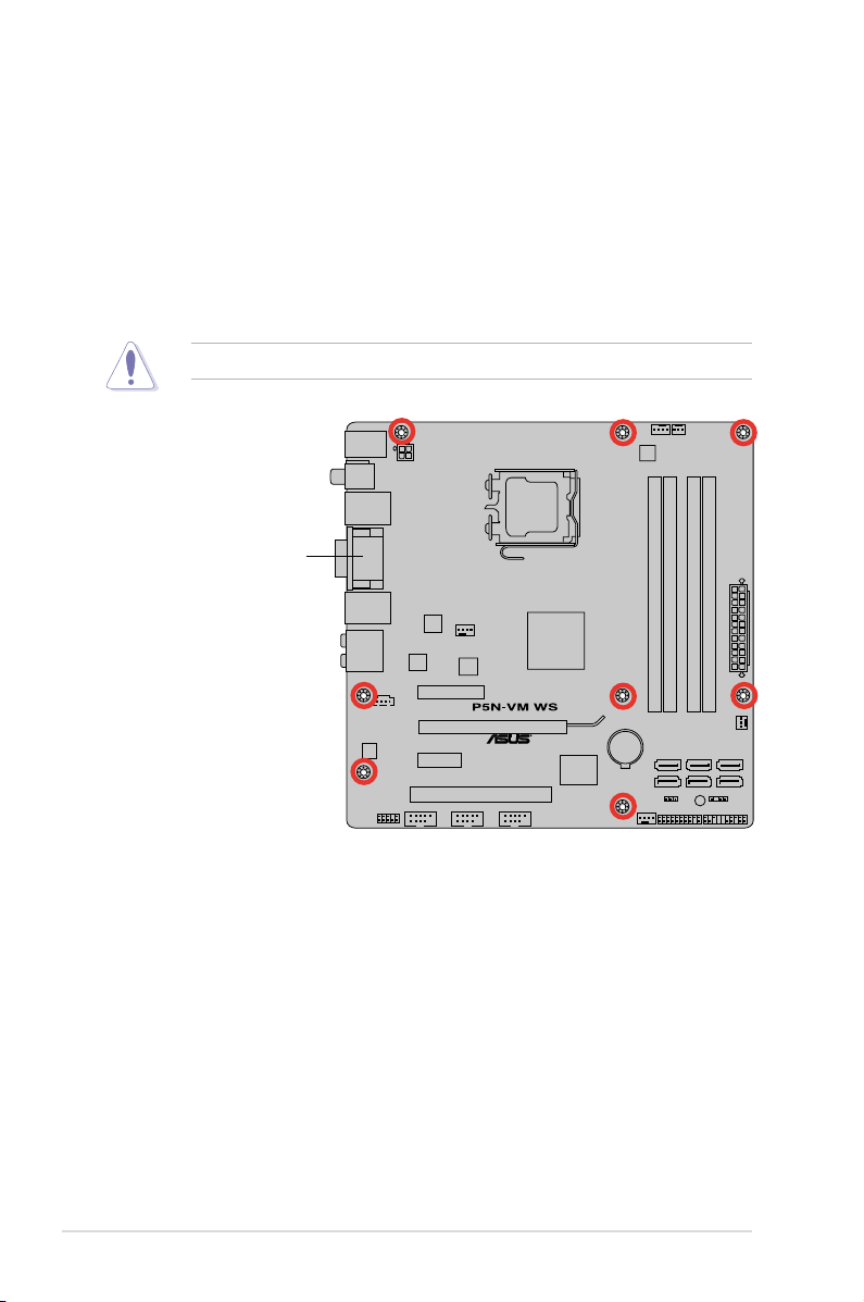
2.2.3 Placement direction
When installing the motherboard, make sure that you place it into the chassis in the
correct orientation. The edge with external ports goes to the rear part of the chassis
as indicated in the image below.
2.2.4 Screw holes
Place eight (8) screws into the holes indicated by circles to secure the motherboard
to the chassis.
Do not overtighten the screws! Doing so can damage the motherboard.
Place this side towards
the rear of the chassis
2-4 Chapter 2: Hardware information
Page 25

2.3 Central Processing Unit (CPU)
The motherboard comes with a surface mount LGA775 socket designed for the
Intel® Core™ 2 Extreme / Core™ 2 Quad / Core™ 2 Duo / Pentium
®
dual-core /
Celeron® dual-core / Celeron processors.
• Make sure that all power cables are unplugged before installing the CPU.
• If installing a dual-core CPU, connect the chassis fan cable to the
CHA_FAN1 connector to ensure system stability.
• Due to the chipset limitation, we recommend you use FSB 800MHz CPU or
above.
• Upon purchase of the motherboard, make sure that the PnP cap is on
the socket and the socket contacts are not bent. Contact your retailer
immediately if the PnP cap is missing, or if you see any damage to the PnP
cap/socket contacts/motherboard components. ASUS will shoulder the cost
of repair only if the damage is shipment/transit-related.
• Keep the cap after installing the motherboard. ASUS will process Return
Merchandise Authorization (RMA) requests only if the motherboard comes
with the cap on the LGA775 socket.
• The product warranty does not cover damage to the socket contacts
resulting from incorrect CPU installation/removal, or misplacement/loss/
incorrect removal of the PnP cap.
ASUS P5N-VM WS 2-5
Page 26
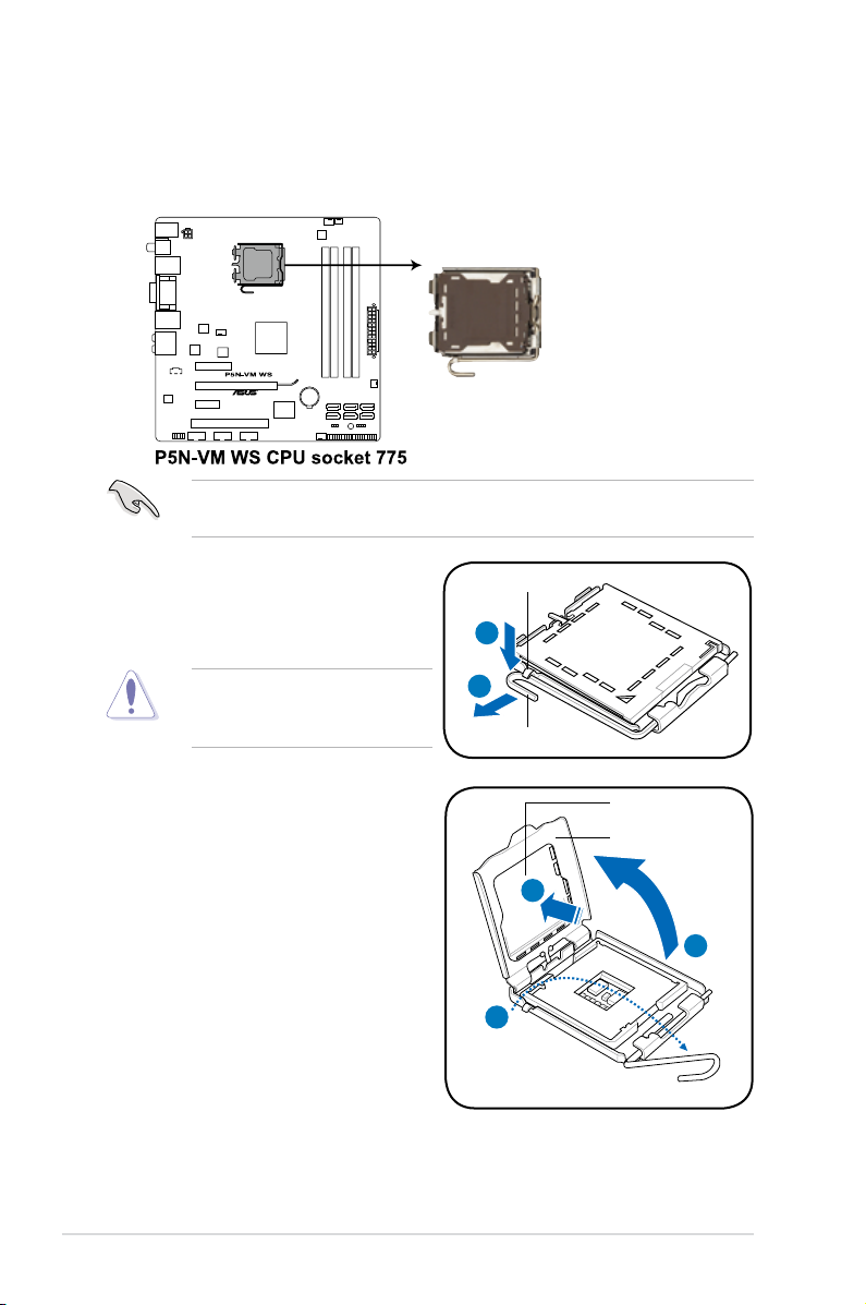
2.3.1 Installing the CPU
To install a CPU:
1. Locate the CPU socket on the motherboard.
Before installing the CPU, make sure that the socket box is facing towards you
and the load lever is on your left.
2. Press the load lever with your
thumb (A), then move it to the left
(B) until it is released from the
retention tab.
To prevent damage to the socket
pins, do not remove the PnP cap
unless you are installing a CPU.
3. Lift the load lever in the direction of
the arrow to a 135º angle.
4. Lift the load plate with your thumb
and forenger to a 100º angle (4A),
then push the PnP cap from the
load plate window to remove (4B).
Retention tab
A
B
Load lever
PnP cap
Load plate
4B
4A
3
2-6 Chapter 2: Hardware information
Page 27
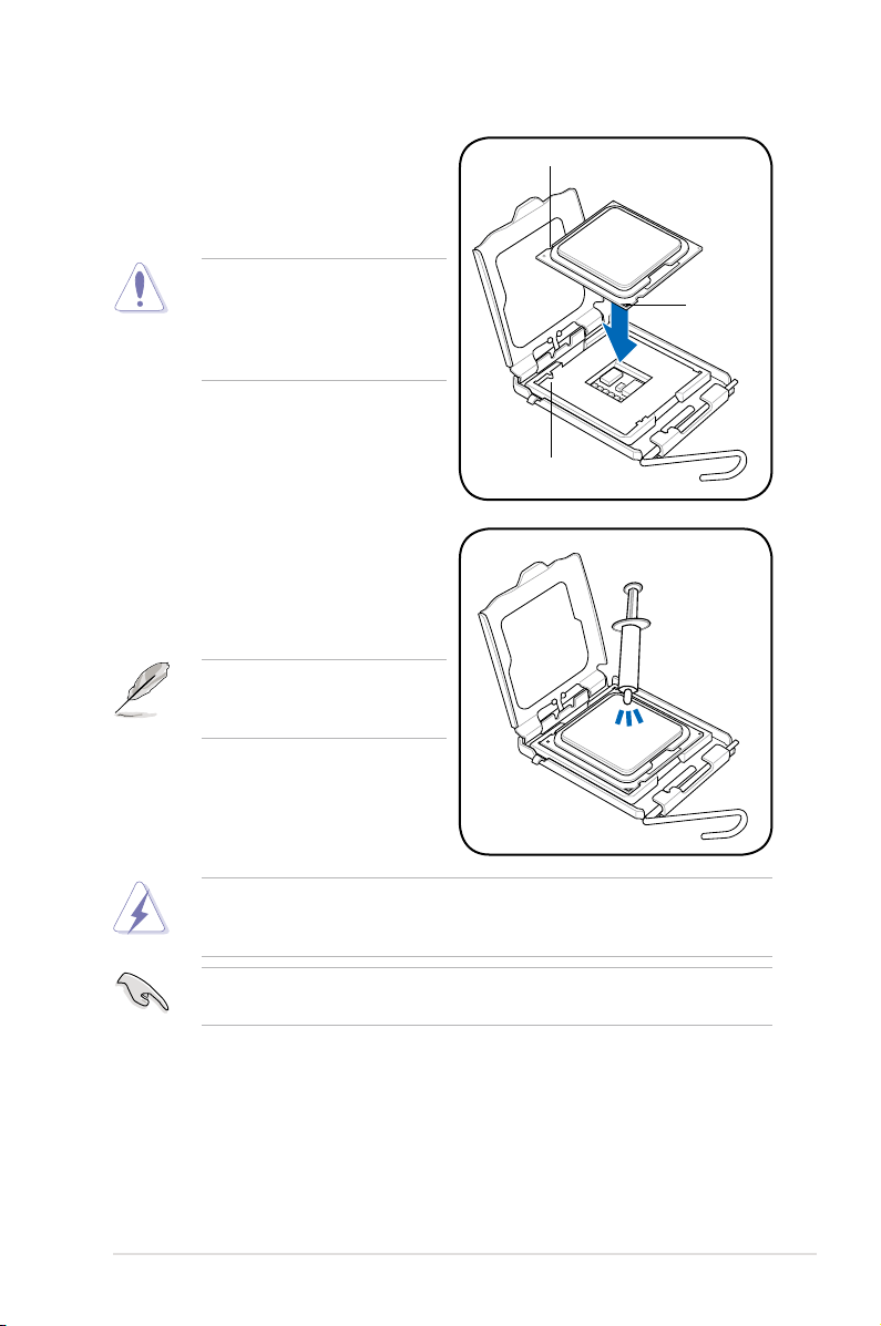
5. Position the CPU over the socket,
making sure that the gold triangle
is on the bottom-left corner of the
socket then t the socket alignment
key into the CPU notch.
The CPU ts in only one correct
orientation. DO NOT force the
CPU into the socket to prevent
bending the connectors on the
socket and damaging the CPU!
6. Apply several drops of thermal paste
to the exposed area of the CPU that
the heatsink will be in contact with,
ensuring that it is spread in an even
thin layer.
Some heatsinks come with preapplied thermal paste. If so, skip
this step.
CPU notch
Gold
triangle
mark
Alignment key
The Thermal Interface Material is toxic and inedible. If it gets into your eyes
or touches your skin, ensure to wash it off immediately, and seek professional
medical help.
To prevent contaminating the paste, DO NOT spread the paste with your nger
directly.
ASUS P5N-VM WS 2-7
Page 28
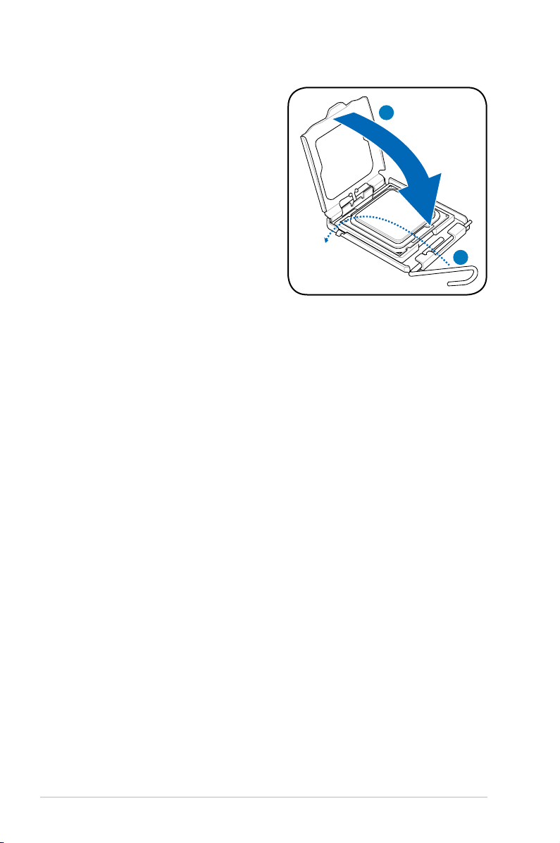
7. Close the load plate (A), then push
the load lever (B) until it snaps into
the retention tab.
A
B
2-8 Chapter 2: Hardware information
Page 29
2.3.2 Installing the CPU heatsink and fan
The Intel® LGA775 processor requires a specially designed heatsink and fan
assembly to ensure optimum thermal condition and performance.
• When you buy a boxed Intel® processor, the package includes the CPU fan
and heatsink assembly. If you buy a CPU separately, make sure that you
use only Intel®-certied multi-directional heatsink and fan.
• Your Intel® LGA775 heatsink and fan assembly comes in a push-pin design
and requires no tool to install.
Make sure that you have installed the motherboard to the chassis before you
install the CPU fan and heatsink assembly.
If you purchased a separate CPU heatsink and fan assembly, ensure that the
Thermal Interface Material is properly applied to the CPU heatsink or CPU
before you install the heatsink and fan assembly.
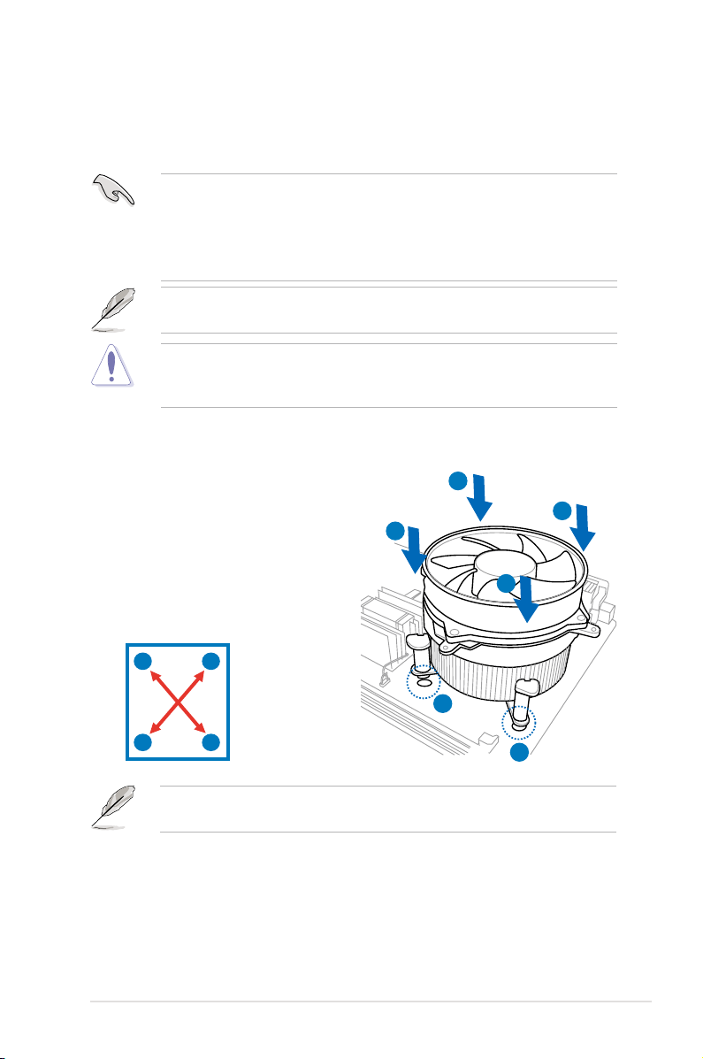
To install the CPU heatsink and fan
1. Place the heatsink on top of the
installed CPU, making sure that the
four fasteners match the holes on
the motherboard.
2. Push down two fasteners at a time
in a diagonal sequence to secure
the heatsink and fan assembly in
place.
A
B
B
A
Orient the heatsink and fan assembly such that the CPU fan cable is closest to
the CPU fan connector.
A
B
B
A
1
1
ASUS P5N-VM WS 2-9
Page 30
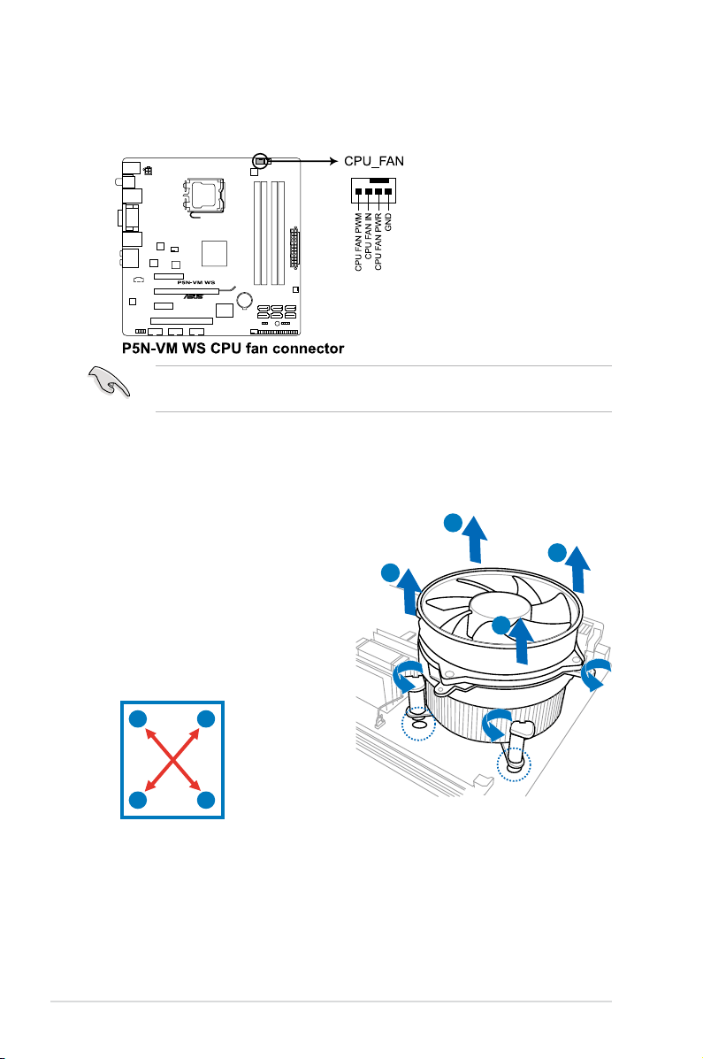
3. Connect the CPU fan cable to the connector on the motherboard labeled
CPU_FAN.
DO NOT forget to connect the CPU fan connector! Hardware monitoring errors
can occur if you fail to plug this connector.
2.3.3 Uninstalling the CPU heatsink and fan
To uninstall the CPU heatsink and fan
1. Disconnect the CPU fan cable from
the connector on the motherboard.
2. Rotate each fastener
counterclockwise.
B
A
B
3. Pull up two fasteners at a time in a
diagonal sequence to disengage the
A
heatsink and fan assembly from the
motherboard.
A
B
B
A
4. Carefully remove the heatsink and fan assembly from the motherboard.
2-10 Chapter 2: Hardware information
Page 31

2.4 System memory
2.4.1 Overview
The motherboard comes with four Double Data Rate II (DDR2) Dual Inline Memory
Modules (DIMM) sockets to support 240-pin DDR2 modules.
The gure illustrates the location of the DDR2 DIMM sockets:
Channel Sockets
Channel A DIMM_A1 and DIMM_A2
Channel B DIMM_B1 and DIMM_B2
Recommend memory conguration
Mode
Single-channel
Dual-channel (1)
Dual-channel (2)
Full
Sockets
DIMM_B1 DIMM_B2 DIMM_A1 DIMM_A2
- - populated populated - - populated - populated -
- populated - populated
populated populated populated populated
ASUS P5N-VM WS 2-11
Page 32

2.4.2 Memory congurations
You may install 512 MB, 1 GB, and 2 GB non-ECC, unbuffered DDR2 DIMMs into
the DIMM sockets.
• You may install varying memory sizes in Channel A and Channel B. The
system maps the total size of the lower-sized channel for the dual-channel
conguration. Any excess memory from the higher-sized channel is then
mapped for single-channel operation.
• Always install DIMMs with the same CAS latency. For optimum
compatibility, it is recommended that you obtain memory modules from the
same vendor.
• Due to the memory address limitation on 32-bit Windows OS, when you
install 4GB or more memory on the motherboard, the actual usable memory
for the OS can be about 3GB or less. For effective use of memory, we
recommend that you install a 64-bit Windows OS when having 4GB or more
memory installed on the motherboard.
• This motherboard does not support memory modules made up of 128 Mb
chips.
The memory modules may require a better cooling system to work stably under
full loading (4 DIMMs) setting.
2-12 Chapter 2: Hardware information
Page 33

P5N-VM WS Motherboard Qualied Vendors List (QVL)
DDR2-800MHz capability
APACER •
N/A
DIMM socket support
(Optional)
A* B* C*
• •
• •
Vendor Part No. Size
A-DATA M2OAD6H3J4171Q1E52 2GB DS AD20908A8A-25EG N/A A-DATA • • •
Apacer 78.01GA0.9K5 1GB SS AM4B5808CQJS8E N/A APACER • • •
Apacer 78.91G9I.9K5 512MB SS AM4B5708JQJS8E N/A APACER •
78.A1GA0.9K4 2GB
Apacer
Box P/N:TWIN2X4096-6400C5
CORSAIR
(CM2X2048-6400C5)
BoxP/N:TWIN2X4096-6400C4DHX
CORSAIR
(CM2X2048-6400C4DHX)
BoxP/N:TWIN2X4096-6400C5DHX
CORSAIR
(CM2X2048-6400C5DHX)
CORSAIR CM2X1024-6400C4 1GB DS Heat-Sink Package 4 N/A • •
Crucial BL12864AA804.16FD3 1GB DS Heat-Sink Package 4 N/A • •
BL12864AL804.16FD3
Crucial
G.SKILL F2-6400CL5D-1GBNQ
G.SKILL F2-6400CL4D-2GBHK 1GB DS Heat-Sink Package N/A N/A • • •
G.SKILL F2-6400CL4D-2GBPK 1GB DS Heat-Sink Package N/A N/A • • •
G.SKILL F2-6400CL4D-4GBPK
G.SKILL F2-6400CL5D-2GBNQ 1GB DS Heat-Sink Package N/A N/A • •
G.SKILL F2-6400CL5D-4GBPQ
G.SKILL F2-6400CL6D-4GBMQ
G.SKILL F2-6400CL6D-8GBNQ
G.SKILL F2-6400PHU2-2GBNR 1GB DS Heat-Sink Package N/A N/A • •
GEIL GB22GB6400C4DC
GEIL GB22GB6400C5DC
GEIL GB24GB6400C4DC
GEIL GB24GB6400C4QC
GEIL GB24GB6400C5DC
GEIL GB24GB6400C5QC
GEIL GB28GB6400C4QC
GEIL GB28GB6400C5QC
GEIL GE22GB800C4DC
GEIL GE22GB800C5DC
GEIL GE24GB800C4DC 2GB DS Heat-Sink Package 4-4-4-12 N/A • •
GEIL GE24GB800C4QC
GEIL GE24GB800C5DC 2GB DS Heat-Sink Package 5-5-5-15 N/A • • •
GEIL GE24GB800C5QC
GEIL GE28GB800C4QC 2GB DS Heat-Sink Package 4-4-4-12 N/A • •
GEIL GE28GB800C5QC 2GB DS Heat-Sink Package 5-5-5-15 N/A • • •
GEIL GX22GB6400C4USC 2GB DS Heat-Sink Package 4-4-4-12 N/A • • •
GEIL GX22GB6400DC
GEIL GX22GB6400LX 2GB DS Heat-Sink Package 5-5-5-15 N/A • • •
GEIL GX22GB6400UDC
GEIL GX24GB6400DC
Hynix HYMP564U64CP8-S5 512MB SS HY5PS12821CFP-S5 5-5-5 Hynix • •
Hynix HYMP 512U64CP8-S5 1GB DS HY5PS12821CFP-S5 5-5-5 Hynix • •
SS/
Chip No. CL Chip Brand
DS
DS AM4B5808CQJS8E
4GB
DS Heat-Sink Package N/A N/A • •
(Kit of 2)
4GB
DS Heat-Sink Package 4-4-4-12 N/A • • •
(Kit of 2)
4GB
DS Heat-Sink Package N/A N/A • •
(Kit of 2)
1GB DS
1GB
(Kit of 2)
4GB
(Kit of 2)
4GB
(Kit of 2)
4GB
(Kit of 2)
8GB
(Kit of 2)
2GB
(Kit of 2)
2GB
(Kit of 2)
4GB
(Kit of 2)
4GB
(Kit of 4)
4GB
(Kit of 2)
4GB
(Kit of 2)
8GB
(Kit of 4)
8GB
(Kit of 4)
2GB
(Kit of 2)
2GB
(Kit of 2)
4GB
(Kit of 4)
4GB
(Kit of 4)
2GB
(Kit of 2)
2GB
(Kit of 2)
4GB
(Kit of 2)
Heat-Sink Package 4
SS Heat-Sink Package 5-5-5-15 N/A • • •
DS Heat-Sink Package 4 N/A •
DS Heat-Sink Package 5 N/A • • •
DS Heat-Sink Package 6 N/A • •
DS Heat-Sink Package 6-6-6-18 N/A • •
DS GL2L64M088BA30EB N/A N/A • • •
DS GL2L64M088BA30EB 5-5-5-15 GEIL • • •
DS GL2L128M88BA25AB 4-4-4-12 GEIL • • •
DS GL2L64M088BA30EB N/A N/A • • •
DS GL2L128M88BA25AB 5-5-5-15 GEIL •
DS GL2L64M088BA30EB N/A N/A • • •
DS GL2L128M88BA25AB N/A N/A • • •
DS GL2L128M88BA25AB N/A N/A •
DS Heat-Sink Package 4-4-4-12 N/A • •
DS Heat-Sink Package 5-5-5-15 N/A • • •
DS Heat-Sink Package N/A N/A • •
DS Heat-Sink Package 5-5-5-15 N/A • • •
DS Heat-Sink Package 5-5-5-15 N/A • • •
DS Heat-Sink Package 4-4-4-12 N/A • • •
DS Heat-Sink Package 5-5-5-15 N/A •
5
•
ASUS P5N-VM WS 2-13
Page 34

P5N-VM WS Motherboard Qualied Vendors List (QVL)
DDR2-800MHz capability (continued)
N/A •
ELPIDA
DIMM socket support
(Optional)
A* B* C*
• •
•
Vendor Part No. Size
KINGMAX KLDC28F-A8KI5 512MB SS KKA8FEIBF-HJK-25A N/A KINGMAX • •
KINGMAX KLDD48F-ABKI5 1GB DS KKA8FEIBF-HJK-25A N/A KINGMAX •
KINGMAX KLDE88F-B8KB5 2GB DS KKB8FFBXF-CFA-25A N/A KINGMAX • •
KHX6400D2/ 512 512MB
KINGSTON
KINGSTON KVR800D2N5/ 512 512MB SS E5108AJBG-8E-E N/A ELPIDA • •
KINGSTON KVR800D2N6/ 512 512MB SS E5108AJBG-8E-E 1.8 ELPIDA • • •
KINGSTON KHX6400D2/2G 2GB DS Heat-Sink Package N/A N/A • • •
KINGSTON KVR800D2N5/1G 1GB DS V59C1 512804QBF25 N/A N/A • • •
KINGSTON KVR800D2N5/2G 2GB DS E1108ACBG-8E-E N/A ELPIDA • •
KVR800D2N6/1G
KINGSTON
KINGSTON KVR800D2N6/4G 4GB DS E2108ABSE-8G-E N/A ELPIDA • • •
NANYA NT 512T64U880BY-25C 512MB SS NT5TU64M8BE-25C 5 NANYA • •
NANYA NT1GT64U8HB0BY-25C 1GB DS NT5TU64M8BE-25C 5 NANYA • • •
NANYA NT1GT64U8HCOBY-25D 1GB DS NT5TU64M8CE-25D N/A NANYA • • •
NANYA NT2GT64U8HC0BY-AC 2GB DS NT5TU128M8CE-AC 5 NANYA • • •
OCZ OCZ2G8001G 1GB DS Heat-Sink Package 5 N/A • • •
OCZ OCZ2P8004GK
OCZ OCZ2P800R22GK
OCZ OCZ2T8002GK 1GB DS Heat-Sink Package N/A N/A • •
PSC AL8E8F73C-8E1 2GB DS A3R1GE3CFF734MAA0E 5 PSC • • •
Qimonda HYS64T 512020EU-2.5-A 4GB DS HYB18T2G800AF-2.5 6 QIMONDA •
Qimonda HYS64T 512020EU-25F-A 4GB DS HYB18T2G800AF-25F 5 QIMONDA • • •
Qimonda HYS64T256020EU-2.5-C2 2GB DS HYB18T1G800C2F-2.5 6 QIMONDA • •
Qimonda HYS64T256020EU-25F-C2 2GB DS HYB18T1G800C2F-25F 5 QIMONDA • • •
SAMSUNG M378T2863QZS-CF7 1GB SS K4T1G084QQ 6 SAMSUNG • • •
SAMSUNG M378T6553GZS-CF7 512MB SS K4T51083QG 6 SAMSUNG • •
SAMSUNG M391T2863QZ3-CF7 1GB SS K4T1G084QQ(ECC) 6 SAMSUNG • •
SAMSUNG M378T2953GZ3-CF7 1GB DS K4T51083QG 6 SAMSUNG • • •
SAMSUNG M378T5263AZ3-CF7 4GB DS K4T2G084QA-HCF7 6 SAMSUNG • • •
Transcend JM800QLJ-1G 1GB DS TQ123PJF8 5 Transcen •
Transcend JM800QLU-2G 2GB DS TQ243PCF8 5 Transcen • • •
Aeneon AET760UD00-25DC08X 1GB SS AET03R25DC 5 Aeneon • •
Aeneon AET760UD00-25DB97X 1GB DS AET93R25DB N/A Aeneon • •
Aeneon AET860UD00-25DC08X 2GB DS AET03R25DC 5 Aeneon • • •
Asint SLY2128M8-JGE 1GB SS DDRII1208-GE N/A Asint • •
Asint SLZ2128M8-JGE 2GB DS DDRII1208-GE N/A Asint • • •
CENTURY 28V2H8 512MB SS HY5PS12821BFP-S5 N/A Hynix • •
CENTURY 28VOH8 1GB DS HY5PS12821BFP-S5 N/A Hynix • •
Elixir M2Y1G64TU88D4B-AC 1GB SS N2TU1G80DE-AC 5 Elixir • • •
Elixir M2Y1G64TU8HB0B-25C 1GB DS N2TU 51280BE-25C 5 Elixir • •
Elixir M2Y2G64TU8HD4B-AC 2GB DS N2TU1G80DE-AC 5 Elixir • • •
Kingbox N/A 2GB DS D9HNL N/A N/A • • •
Kingbox N/A 2GB DS EPD2128082200E-3 N/A Kingbox • •
Oci 04701G16CZ5D2A 1GB DS 64M8PC6400 5 Innity • •
Patriot PSD2 51280081 512MB SS PM64M8D2BU-25EC N/A N/A • •
Patriot PSD22GB002 2GB DS PM128M8D2BU-25KC 5 Patriot • • •
Team TEDD1024M800HC5 1GB DS Heat-Sink Package 5-5-5-15 N/A • •
Team TEDD2048M800HC5 2GB DS Heat-Sink Package 5-5-5-15 N/A • •
UMAX U2S12D30TP-8E 1GB DS D48001GP3-63BJU N/A UMAX • • •
SS/
Chip No. CL Chip Brand
DS
SS Heat-Sink Package
1GB DS
4GB
(Kit of 2)
2GB
(Kit of 2)
E5108AJBG-8E-E 1.8
DS Heat-Sink Package 5-4-4 N/A • • •
DS Heat-Sink Package 4 N/A •
N/A
•
2-14 Chapter 2: Hardware information
Page 35

P5N-VM WS Motherboard Qualied Vendors List (QVL)
DDR2-667MHz capability
N/A •
N/A
DIMM socket support
(Optional)
A* B* C*
• •
• •
Vendor Part No. Size
Apacer 78.01G9O.9K5 1GB SS AM4B5808CQJS7E N/A APACER • • •
Apacer 78.91G92.9K5 512MB SS AM4B5708JQJS7E N/A APACER •
Apacer 78.A1G9O.9K4 2GB DS AM4B5808CQJS7E N/A APACER • • •
CORSAIR
CORSAIR VS1GB667D2 1GB DS 64M8CFEG N/A N/A • • •
crucial BL6464AA663.8FD 512MB SS Heat-Sink Package 3 N/A •
crucial BL12864AA663.16FD2 1GB DS Heat-Sink Package 3 N/A •
crucial BL12864AA663.16FD 1GB DS Heat-Sink Package 3 N/A •
ELPIDA EBE51UD8AEFA-6E-E 512MB SS E5108AE-6E-E 5 ELPIDA • •
G.SKILL
G.SKILL F2-5400PHU2-2GBNT 2GB (Kit of 2) DS D264M8GCF 5-5-5-15 G.SKILL • • •
GEIL GX21GB5300SX 1GB DS Heat-Sink Package 3-4-4-8 N/A • • •
GEIL GX22GB5300LX 2GB DS Heat-Sink Package 5-5-5-15 N/A • •
GEIL GX24GB5300LDC 4GB (Kit of 2) DS Heat-Sink Package 5-5-5-15 N/A •
Hynix HYMP112U64CP8-Y5 1GB SS HY5PS1G831CFP-Y5 5 Hynix • • •
Hynix HYMP 512U64CP8-Y5 1GB DS HY5PS12821CFP-Y5 5 Hynix • • •
KINGSTON KVR667D2N5/ 512 512MB SS D6408TEBGGL3U 5 KINGSTON • • •
KINGSTON KVR667D2E5/2G 2GB DS D9HNL(ECC) N/A MICRON •
KINGSTON KVR667D2N5/1G 1GB DS E5108AJBG-8E-E N/A ELPIDA • • •
KINGSTON KVR667D2N5/1G 1GB DS HY5PS12821CFP-Y5 N/A Hynix • •
KINGSTON KVR667D2N5/2G 2GB DS E1108AB-6E-E N/A ELPIDA • •
KINGSTON KVR667D2N5/2G 2GB DS HY5PS1G831CFP-Y5 N/A Hynix • •
NANYA NT 512T64U88B0BY-3C 512MB SS NT5TU64M8BE-3C 5 NANYA • •
NANYA NT2GT64U8HB0JY-3C 2GB DS NT5TU128M8BJ-3C 5 NANYA •
PSC AL7E8E63J-6E1 1GB DS A3R12E3JFF719A9T02 5 PSC • • •
SAMSUNG M378T6553EZS-CE6 512MB SS K4T51083QE 5 SAMSUNG • •
SAMSUNG M378T2953EZ3-CE6 1GB DS K4T51083QE 5 SAMSUNG • • •
SAMSUNG M378T5263AZ3-CE6 4GB DS K4T2G084QA-HCE6 5 SAMSUNG • •
Super Talent T6UA 512C5 512MB SS Heat-Sink Package 5 N/A • •
Super Talent T6UB1GC5 1GB DS Heat-Sink Package 5 N/A • • •
Transcend JM667QLU-2G 2GB DS TQ243ECF8 5 Transcend •
TwinMOS 8D-23JK5M2ETP 512MB SS TMM6208G8M30C 5 TwinMOS • •
VS 512MB667D2 512MB
F2-5300CL5D-4GBMQ
4GB (Kit of 2) DS
SS/
Chip No. CL Chip Brand
DS
SS 64M8CFEG
Heat-Sink Package 5-5-5-15
N/A
Side(s): SS - Single-sided DS - Double-sided
DIMM support:
• A*: Supports one module inserted into either slot as Single-channel
memory conguration.
• B*: Supports one pair of modules inserted into either the yellow slots or the
black slots as one pair of Dual-channel memory conguration.
• C*: Supports four modules inserted into both the yellow slots and the
black slots as two pairs of Dual-channel memory conguration.
•
Visit the ASUS website for the latest QVL.
ASUS P5N-VM WS 2-15
Page 36

2.4.3 Installing a DIMM
Make sure to unplug the power supply before adding or removing DIMMs or
other system components. Failure to do so may cause severe damage to both
the motherboard and the components.
1. Unlock a DDR2 DIMM socket
by pressing the retaining clips
outward.
2. Align a DIMM on the socket
such that the notch on the DIMM
matches the break on the socket.
Unlocked retaining clip
A DDR2 DIMM is keyed with a notch so that it ts in only one direction. DO NOT
force a DIMM into a socket to avoid damaging the DIMM.
2
DDR2 DIMM notch
1
1
3. Firmly insert the DIMM into the
3
socket until the retaining clips snap
back in place and the DIMM is
properly seated.
Locked Retaining Clip
2.4.4 Removing a DIMM
Follow these steps to remove a DIMM.
1. Simultaneously press the
retaining clips outward to unlock
the DIMM.
Support the DIMM lightly with your ngers when pressing the retaining clips.
The DIMM might get damaged when it ips out with extra force.
1
2. Remove the DIMM from the socket.
2-16 Chapter 2: Hardware information
2
DDR2 DIMM notch
1
Page 37

2.5 Expansion slots
In the future, you may need to install expansion cards. The following sub-sections
describe the slots and the expansion cards that they support.
Make sure to unplug the power cord before adding or removing expansion
cards. Failure to do so may cause you physical injury and damage motherboard
components.
2.5.1 Installing an expansion card
To install an expansion card:
1. Before installing the expansion card, read the documentation that came with
it and make the necessary hardware settings for the card.
2. Remove the system unit cover (if your motherboard is already installed in a
chassis).
3. Remove the bracket opposite the slot that you intend to use. Keep the screw
for later use.
4. Align the card connector with the slot and press rmly until the card is
completely seated on the slot.
5. Secure the card to the chassis with the screw you removed earlier.
6. Replace the system cover.
2.5.2 Conguring an expansion card
After installing the expansion card, congure it by adjusting the software settings.
1. Turn on the system and change the necessary BIOS settings, if any. See
Chapter 3 for information on BIOS setup.
2. Assign an IRQ to the card. Refer to the tables on the next page.
3. Install the software drivers for the expansion card.
• When using PCI cards on shared slots, ensure that the drivers support
“Share IRQ” or that the cards do not need IRQ assignments. Otherwise,
conicts will arise between the two PCI groups, making the system unstable
and the card inoperable. Refer to the table on the next page for details.
• By default, if you install a discrete graphics card on the PCIe x16 slot, the
onboard GPU will be automatically disabled. Connect the VGA cable to
the discrete graphics card rst when using a discrete graphics card. To
use quad-display, enable both the onboard GPU and the discrete Quadro
graphics card. See section
for details.
ASUS P5N-VM WS 2-17
3.4.2 Chipset > Southbridge Conguration
Page 38

2.5.3 Interrupt assignments
IRQ Priority Standard function
0 1 System timer
1 2 Keyboard controller
2
3 11 IRQ holder for PCI steering*
5 13 IRQ holder for PCI steering*
7
8 3 System CMOS/Real Time Clock
9 4 IRQ holder for PCI steering*
10 5 IRQ holder for PCI steering*
11 6 IRQ holder for PCI steering*
12 7 PS/2 compatible mouse port*
13 8 Numeric data processor
14 9 IRQ holder for PCI steering*
15 10 IRQ holder for PCI steering*
* These IRQs are usually available for PCI devices.
IRQ assignments for this motherboard
PCI slot Shared — — — — — — — — — — — —
PCIe x16
slot
RTL
8111C_1
RTL
8111C_2
PCIe x4 slot — — — — Shared — — — — — — — —
PCIe x1 slot — — — — — Shared — — — — — — —
USB 1.1
(OHCI)
USB 2.0
(EHCI)
USB1 1.1
(OHCI)
USB1 2.0
(EHCI)
HDA
(Azalia)
SB Internal
GPU
SATA
Controller
– Re-direct to IRQ#9
15 IRQ holder for PCI steering*
LNKC LN0A LN3A LN4A LN5A LN6A SGRU LUB0 LUB2 UB11 UB12 LSA0 LAZA
— Shared — — — — — — — — — — —
— — Shared — — — — — — — — — —
— — — Shared — — — — — — — — —
— — — — — — — Shared — — — — —
— — — — — — — — Shared — — — —
— — — — — — — — — Shared — — —
— — — — — — — — — — Shared — —
— — — — — — — — — — — — Shared
— — — — — — Shared — — — — — —
— — — — — — — — — — — Shared —
2-18 Chapter 2: Hardware information
Page 39

2.5.4 PCI Express 2.0 x16 slot
This motherboard has one PCI Express 2.0 x16 slot that supports PCI Express
2.0 x16 graphics cards complying with the PCI Express specications. Refer to the
gure below for the location of the slots.
2.5.5 PCI Express x4 slot
This motherboard supports PCI Express x4 network cards, SAS cards and other
cards that comply with the PCI Express specications. Refer to the gure below for
the location of the slot.
2.5.6 PCI Express x1 slot
This motherboard supports PCI Express x1 network cards and other cards that
comply with the PCI Express specications. Refer to the gure below for the
location of the slot.
Install a PCIe x1 device to a PCIe x1 slot prior to a PCIe x16 slot.
2.5.7 PCI slots
The PCI slots support cards such as a LAN card, SCSI card, USB card, and other
cards that comply with PCI specications. Refer to the gure below for the location
of the slots.
PCI_1 slot
PCIe x1_1 slot (at x1 link)
PCIe 2.0 x16_1 slot (at x16 link)
PCIe x4_1 slot (at x1 link)
ASUS P5N-VM WS 2-19
Page 40

2.6 Jumper
Clear RTC RAM (3-pin CLRTC)
This jumper allows you to clear the Real Time Clock (RTC) RAM in CMOS. You can
clear the CMOS memory of date, time, and system setup parameters by erasing
the CMOS RTC RAM data. The onboard button cell battery powers the RAM data
in CMOS, which include system setup information such as system passwords.
To erase the RTC RAM
1. Turn OFF the computer and unplug the power cord.
2. Move the jumper cap from pins 1–2 (default) to pins 2–3. Keep the cap
on pins 2–3 for about 5–10 seconds, then move the cap back to pins 1–2.
3. Plug the power cord and turn ON the computer.
4. Hold down the <Del> key during the boot process and enter BIOS setup
to re-enter data.
Except when clearing the RTC RAM, never remove the cap on CLRTC jumper
default position. Removing the cap will cause system boot failure!
If the steps above do not help, remove the onboard battery and move the
jumper again to clear the CMOS RTC RAM data. After the CMOS clearance,
reinstall the battery.
2-20 Chapter 2: Hardware information
Page 41

2.7 Connectors
2.7.1 Rear panel connectors
1. PS/2 keyboard / mouse combo port
. This port is for a PS/2 keyboard or
mouse.
2. Coaxial S/PDIF Out port
. This port connects an external audio output device
via a coaxial S/PDIF cable.
3. LAN2 (RJ-45) port
. Supported by Realtek® Gigabit LAN controller, this port
allows Gigabit connection to a Local Area Network (LAN) through a network
hub. Refer to the table on the next page for the LAN port LED indications.
4. DVI-I out ports
. These ports are for any DVI-I compatible device and are
HDCP compliant, allowing playback of HD DVDi, Blu-Ray and other protected
content.
• This motherboard comes with dual-DVI output that features different
displays on 2 monitors at the same time if you connect 2 monitors to
both the DVI-I ports. The upper DVI-I port supports Single Link with max.
resolution up to 1920x1200. The lower DVI-I port supports Dual Link with
max resolution up to 2560x1600.
Playback of HD DVD and Blu-Ray Discs
• For better playback quality, we recommend that you follow the system
requirements listed below.
File format
Non-protected clips 1920 x 1080p 1920 x 1080p
HD-DVD 1920 x 1080p 1280 x 1080p
• Supported DVD formats: VC-1, H.264, and MPEG-2.
• To play HD DVD or Blu-Ray Disc, ensure to use HDCP compliant devices
Blu-Ray 1280 x 1080p 1280 x 1080p
and softwares.
Windows XP Windows Vista
Best resolution
5. LAN1 (RJ-45) port
. Supported by Realtek® Gigabit LAN controller, this port
allows Gigabit connection to a Local Area Network (LAN) through a network
hub. Refer to the table on the next page for the LAN port LED indications.
ASUS P5N-VM WS 2-21
Page 42

LAN port LED indications
LED
LAN port
SPEED
LED
Activity/Link LED Speed LED
Status Description Status Description
OFF No link OFF 10 Mbps connection
YELLOW Linked ORANGE 100 Mbps connection
BLINKING Data activity GREEN 1 Gbps connection
6. Center/Subwoofer port (orange)
. This port connects the center/subwoofer
ACT/LINK
speakers.
7. Rear Speaker Out port (black)
. This port connects the rear speakers in a
4-channel, 6-channel, or 8-channel audio conguration.
8. Line In port (light blue)
. This port connects the tape, CD, DVD player, or
other audio sources.
9. Line Out port (lime)
. This port connects a headphone or a speaker. In
4-channel, 6-channel, and 8-channel conguration, the function of this port
becomes Front Speaker Out.
10. Microphone port (pink)
11. Side Speaker Out port (gray)
. This port connects a microphone.
. This port connects the side speakers in an
8-channel audio conguration.
Refer to the audio conguration table below for the function of the audio ports in
2, 4, 6, or 8-channel conguration.
Audio 2, 4, 6, or 8-channel conguration
Port
Light Blue Line In Line In Line In Line In
Lime Line Out Front Speaker Out Front Speaker Out Front Speaker Out
Pink Mic In Mic In Mic In Mic In
Orange – – Center/Subwoofer Center/Subwoofer
Black – Rear Speaker Out Rear Speaker Ou Rear Speaker Out
Gray – – – Side Speaker Out
Headset
2-channel
4-channel 6-channel 8-channel
12. USB 2.0 ports 1 and 2
. These two 4-pin Universal Serial Bus (USB) ports
are available for connecting USB 2.0 devices.
13. USB 2.0 ports 3 and 4
. These two 4-pin Universal Serial Bus (USB) ports
are available for connecting USB 2.0 devices.
14. Optical S/PDIF Out port
. This port connects an external audio output device
via an optical S/PDIF cable.
15. USB 2.0 ports 5 and 6
. These two 4-pin Universal Serial Bus (USB) ports
are available for connecting USB 2.0 devices.
2-22 Chapter 2: Hardware information
Page 43

2.7.2 Internal connectors
1. NVIDIA® Quadro FX470 Serial ATA connectors (7-pin SATA1-4 [red];
7-pin SATA5-6 [black])
These connectors are for the Serial ATA signal cables for Serial ATA hard disk
drives and optical disk drives.
• SATA1-4 connectors are set to [IDE] by default. If you intend to create a
SATA RAID set using these connectors, set the SATA Mode select item in
the BIOS to [RAID Mode].
• SATA 5-6 connectors support RAID mode and AHCI mode only. To use
these connectors, set the SATA Mode select item in the BIOS to [RAID
mode] or [AHCI Mode].
• SATA devices connected to SATA 5-6 connectors can be used only as data
storage devices. Do not connect a boot device to the SATA 5-6 connectors.
• Due to chipset limitation, when set any of SATA ports to RAID or AHCI
mode, all SATA ports run at RAID or AHCI mode together.
• If you intend to use SATA hard disk drives in RAID or AHCI mode, ensure to
create a RAID / AHCI driver disk using the motherboard support DVD, and
then load the RAID / AHCI driver during OS installation.
• You must install the Windows XP® Service Pack 1 before using SATA
hard disk drives. The SATA RAID feature is available only if you are using
Windows XP® or later version.
Connect the right-angle side
of SATA signal cable to SATA
device. Or you may connect the
right-angle side of SATA cable to
the onboard SATA port to avoid
mechanical conict with huge
graphics cards.
ASUS P5N-VM WS 2-23
Right angle side
Page 44
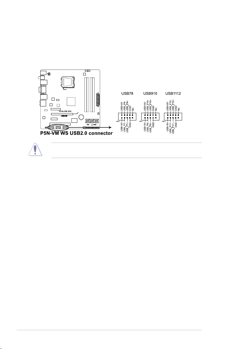
2. USB connectors (10-1 pin USB78, USB910, USB1112)
These connectors are for USB 2.0 ports. Connect the USB module cable
to any of these connectors, then install the module to a slot opening at the
back of the system chassis. These USB connectors comply with USB 2.0
specication that supports up to 480 Mbps connection speed.
Never connect a 1394 cable to the USB connectors. Doing so will damage the
motherboard!
2-24 Chapter 2: Hardware information
Page 45

3. Optical drive audio connector (4-pin CD)
These connectors allow you to receive stereo audio input from sound sources
such as a CD-ROM, TV tuner, or MPEG card.
4. TPM connector (20-1 pin TPM)
This connector supports a Trusted Platform Module (TPM) system, which can
securely store keys, digital certicates, passwords, and data. A TPM system
also helps enhance network security, protects digital identities, and ensures
platform integrity.
The TPM module is purchased separately.
ASUS P5N-VM WS 2-25
Page 46
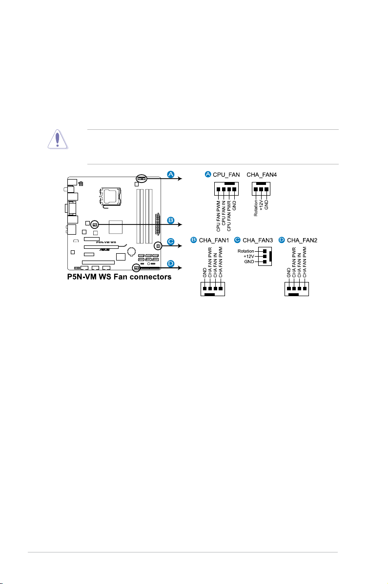
5. CPU and chassis fan connectors (4-pin CPU_FAN, 4-pin CHA_FAN1-2,
3-pin CHA_FAN3-4)
The fan connectors support cooling fans of 350 mA~2000 mA (24 W max.)
or a total of 1 A~7 A (84 W max.) at +12V. Connect the fan cables to the fan
connectors on the motherboard, making sure that the black wire of each
cable matches the ground pin of the connector.
Do not forget to connect the fan cables to the fan connectors. Insufcient air
ow inside the system may damage the motherboard components. These are
not jumpers! Do not place jumper caps on the fan connectors!
2-26 Chapter 2: Hardware information
Page 47

6. Front panel audio connector (10-1 pin AAFP)
This connector is for a chassis-mounted front panel audio I/O module that
supports either HD Audio or legacy AC`97 audio standard. Connect one end
of the front panel audio I/O module cable to this connector.
7. Chassis intrusion connector (4-1 pin CHASSIS)
This connector is for a chassis-mounted intrusion detection sensor or switch.
Connect one end of the chassis intrusion sensor or switch cable to this
connector. The chassis intrusion sensor or switch sends a high-level signal to
this connector when a chassis component is removed or replaced. The signal
is then generated as a chassis intrusion event.
By default, the pin labeled “Chassis Signal” and “Ground” are shorted with
a jumper cap. Remove the jumper caps only when you intend to use the
chassis intrusion detection feature.
ASUS P5N-VM WS 2-27
Page 48

8. ATX power connectors (24-pin EATXPWR, 4-pin EATX12V)
These connectors are for ATX power supply plugs. The power supply plugs
are designed to t these connectors in only one orientation. Find the proper
orientation and push down rmly until the connectors completely t.
• Do not forget to connect the 4-pin EATX12V power plug; otherwise, the
system will not boot.
• Use of a PSU with a higher power output is recommended when
conguring a system with more power-consuming devices. The system
may become unstable or may not boot up if the power is inadequate.
• If you are uncertain about the minimum power supply requirement for your
system, refer to the Recommended Power Supply Wattage Calculator
at http://support.asus.com/PowerSupplyCalculator/PSCalculator.
aspx?SLanguage=en-us for details.
PSU suggested list
PSU suggested list
ACBEL POLYTECH INC PC7057-Z6AG 390W W/PFC
ACBEL POLYTECH INC PC7009-000G 380W W/PFC
2-28 Chapter 2: Hardware information
Page 49

9. System panel connector (20-8 pin PANEL)
This connector supports several chassis-mounted functions.
•
System power LED (2-pin PLED)
This 2-pin connector is for the system power LED. Connect the chassis
power LED cable to this connector. The system power LED lights up when
you turn on the system power, and blinks when the system is in sleep mode.
•
Hard disk drive activity LED (2-pin IDE_LED)
This 2-pin connector is for the HDD Activity LED. Connect the HDD Activity
LED cable to this connector. The IDE LED lights up or ashes when data is
read from or written to the HDD.
•
System warning speaker (4-pin SPEAKER)
This 4-pin connector is for the chassis-mounted system warning speaker. The
speaker allows you to hear system beeps and warnings.
•
ATX power button/soft-off button (2-pin PWRSW)
This connector is for the system power button. Pressing the power button
turns the system on or puts the system in sleep or soft-off mode depending
on the BIOS settings. Pressing the power switch for more than four seconds
while the system is ON turns the system OFF.
•
Reset button (2-pin RESET)
This 2-pin connector is for the chassis-mounted reset button for system
reboot without turning off the system power.
ASUS P5N-VM WS 2-29
Page 50

2.8 Starting up for the rst time
1. After making all the connections, replace the system case cover.
2. Be sure that all switches are off.
3. Connect the power cord to the power connector at the back of the system
chassis.
4. Connect the power cord to a power outlet that is equipped with a surge
protector.
5. Turn on the devices in the following order:
a. Monitor
b. External SCSI devices (starting with the last device on the chain)
c. System power
6. After applying power, the system power LED on the system front panel case
lights up. For systems with ATX power supplies, the system LED lights up
when you press the ATX power button. If your monitor complies with “green”
standards or if it has a “power standby” feature, the monitor LED may light up
or switch between orange and green after the system LED turns on.
The system then runs the power-on self tests or POST. While the tests are
running, the BIOS beeps (see BIOS beep codes table below) or additional
messages appear on the screen. If you do not see anything within 30
seconds from the time you turned on the power, the system may have failed a
power-on test. Check the jumper settings and connections or call your retailer
for assistance.
AMI BIOS beep codes
BIOS Beep Description
One short beep VGA detected
One continuous beep followed by two
short beeps then a pause (repeated)
One continuous beep followed by three
short beeps
One continuous beep followed by four
short beeps
Quick boot set to disabled
No keyboard detected
No memory detected
No VGA detected
Hardware component failure
7. At power on, hold down the <Delete> key to enter the BIOS Setup. Follow the
instructions in Chapter 3.
2-30 Chapter 2: Hardware information
Page 51

2.9 Turning off the computer
2.9.1 Using the OS shut down function
If you are using Windows® XP or later version:
1. Click the Start button then select Turn Off Computer.
2. Click the Turn Off button to shut down the computer.
3. The power supply should turn off after Windows® shuts down.
If you are using Windows® Vista:
1. Click the Start button then select ShutDown.
2. The power supply should turn off after Windows® shuts down.
2.9.2 Using the dual function power switch
While the system is ON, pressing the power switch for less than four seconds puts
the system to sleep mode or to soft-off mode, depending on the BIOS setting.
Pressing the power switch for more than four seconds lets the system enter the
soft-off mode regardless of the BIOS setting. Refer to section
Chapter 3 for details.
3.5 Power Menu
in
ASUS P5N-VM WS 2-31
Page 52

2-32 Chapter 2: Hardware information
Page 53

This chapter tells how to change the
system settings through the BIOS Setup
menus. Detailed descriptions of the
BIOS parameters are also provided.
BIOS setup
3
Page 54

Chapter summary
3
3.1 Managing and updating your BIOS ............................................ 3-1
3.2 BIOS setup program .................................................................... 3-9
3.3 Main menu .................................................................................. 3-12
3.4 Advanced menu ......................................................................... 3-17
3.5 Power menu ................................................................................ 3-23
3.6 Boot menu .................................................................................. 3-26
3.7 Tools menu ................................................................................. 3-30
3.8 Exit menu .................................................................................... 3-32
ASUS P5N-VM WS
Page 55

3.1 Managing and updating your BIOS
The following utilities allow you to manage and update the motherboard Basic
Input/Output System (BIOS) setup.
1. ASUS Update (Updates the BIOS in Windows® environment.)
2. ASUS EZ Flash 2 (Updates the BIOS using a oppy disk or USB ash disk.)
3. ASUS AFUDOS (Updates the BIOS using a bootable oppy disk.)
4. ASUS CrashFree BIOS 3 (Updates the BIOS using a bootable oppy disk,
USB ash disk or the motherboard support DVD when the BIOS le fails or
gets corrupted.)
Refer to the corresponding sections for details on these utilities.
Save a copy of the original motherboard BIOS le to a bootable oppy disk or
USB ash disk in case you need to restore the BIOS in the future. Copy the
original motherboard BIOS using the ASUS Update or AFUDOS utilities.
3.1.1 ASUS Update utility
The ASUS Update is a utility that allows you to manage, save, and update the
motherboard BIOS in Windows® environment. The ASUS Update utility allows you
to:
• Save the current BIOS le
• Download the latest BIOS le from the Internet
• Update the BIOS from an updated BIOS le
• Update the BIOS directly from the Internet, and
• View the BIOS version information.
This utility is available in the support DVD that comes with the motherboard
package.
ASUS Update requires an Internet connection either through a network or an
Internet Service Provider (ISP).
Installing ASUS Update
To install ASUS Update:
1. Place the support DVD in the optical drive. The Drivers menu appears.
2. Click the Utilities tab, then click Install ASUS Update VX.XX.XX.
3. The ASUS Update utility is copied to your system.
ASUS P5N-VM WS 3-1
Page 56

Quit all Windows® applications before you update the BIOS using this utility.
Updating the BIOS through the Internet
To update the BIOS through the Internet:
1. Launch the ASUS Update utility from the Windows® desktop by clicking Start
> Programs > ASUS > ASUSUpdate > ASUSUpdate. The ASUS Update
main window appears.
2. Select Update BIOS from the
Internet option from the drop-down
menu, then click Next.
3-2 Chapter 3: BIOS setup
3. Select the ASUS FTP site nearest
you to avoid network trafc, or
click Auto Select. Click Next.
Page 57

4. From the FTP site, select the BIOS
version that you wish to download.
Click Next.
5. Follow the screen instructions to
complete the update process.
The ASUS Update utility is
capable of updating itself through
the Internet. Always update the
utility to avail all its features.
Updating the BIOS through a BIOS le
To update the BIOS through a BIOS le:
1. Launch the ASUS Update utility from the Windows® desktop by clicking Start
> Programs > ASUS > ASUSUpdate > ASUSUpdate. The ASUS Update
main window appears.
2. Select Update BIOS from a le
option from the drop-down menu,
then click Next.
3. Locate the BIOS le from the Open
window, then click Open.
4. Follow the screen instructions to
P5NVMWS.ROM
complete the update process.
P5NVMWS
ASUS P5N-VM WS 3-3
Page 58

3.1.2 ASUS EZ Flash 2 utility
The ASUS EZ Flash 2 feature allows you to update the BIOS without having to go
through the long process of booting from a oppy disk and using a DOS-based
utility. The EZ Flash 2 utility is built in the BIOS chip so it is accessible by pressing
<Alt> + <F2> during the Power-On Self Tests (POST).
To update the BIOS using EZ Flash 2:
1. Visit the ASUS website (www.asus.com) to download the latest BIOS le for
the motherboard.
2. Save the BIOS le to a oppy disk or a USB ash disk, then restart the
system.
3. You can launch the EZ Flash 2 by two methods.
(1) Insert the oppy disk / USB ash disk that contains the BIOS le to the
oppy disk drive or the USB port.
Press <Alt> + <F2> during POST to display the following.
ASUSTek EZ Flash 2 BIOS ROM Utility V3.24
FLASH TYPE: MXIC 25L8005
Current ROM
BOARD: P5N-VM WS
VER: 0403
DATE: 09/17/2008
PATH: A:\
A:
Update ROM
BOARD: Unknown
VER: Unknown
DATE: Unknown
Note
[Enter] Select or Load [Tab] Switch [V] Drive Info
[Up/Down/Home/End] Move [B] Backup [ESC] Exit
(2) Enter BIOS setup program. Go to the Tools menu to select EZ Flash 2
and press <Enter> to enable it.
You can switch between drives by pressing <Tab> before the correct le
is found. Then press <Enter>.
4. When the correct BIOS le is found, EZ Flash 2 performs the BIOS update
process and automatically reboots the system when done.
• This function can support devices such as a USB ash disk or a oppy disk
with FAT 32/16 format and single partition only.
• Do not shut down or reset the system while updating the BIOS to prevent
system boot failure!
3-4 Chapter 3: BIOS setup
Page 59

3.1.3 Creating a bootable oppy disk
The motherboard does not provide a oppy drive connector. You have to use a
USB oppy drive when creating a bootable oppy disk.
1. Do either one of the following to create a bootable oppy disk.
DOS environment
a. Insert a 1.44MB oppy disk into the drive.
b. At the DOS prompt, type
Windows® XP environment
a. Insert a 1.44 MB oppy disk to the oppy disk drive.
b. Click Start from the Windows® desktop, then select My Computer.
c. Select the 3 1/2 Floppy Drive icon.
d. Click File from the menu, then select Format. A Format 3 1/2 Floppy
Disk window appears.
e. Select Create an MS-DOS startup disk from the format options eld,
then click Start.
Windows® Vista environment
a. Insert a formatted, high density 1.44 MB oppy disk to the oppy disk
drive.
b. Click from the Windows® desktop, then select Computer.
c. Right-click Floppy Disk Drive then click Format to display the Format
3 1/2 Floppy dialog box .
d. Select the Create an MS-DOS startup disk check box.
e. Click Start.
2. Copy the original or the latest motherboard BIOS le to the bootable oppy
disk.
format
A:/S then press <Enter>.
ASUS P5N-VM WS 3-5
Page 60

3.1.4 AFUDOS utility
The AFUDOS utility allows you to update the BIOS le in DOS environment using
a bootable oppy disk with the updated BIOS le. This utility also allows you to
copy the current BIOS le that you can use as backup when the BIOS fails or gets
corrupted during the updating process.
The motherboard does not provide a oppy drive connector. You have to use a
USB oppy drive to use the AFUDOS utility.
Copying the current BIOS
To copy the current BIOS le using the AFUDOS utility:
• Make sure that the oppy disk is not write-protected and has at least
1024KB free space to save the le.
• The succeeding BIOS screens are for reference only. The actual BIOS
screen displays may not be same as shown.
1. Copy the AFUDOS utility (afudos.exe) from the motherboard support DVD to
the bootable oppy disk you created earlier.
2. Boot the system in DOS mode, then at the prompt type:
afudos /o[lename]
where the [lename] is any user-assigned lename not more than eight
alphanumeric characters for the main lename and three alphanumeric
characters for the extension name.
A:\>afudos /oOLDBIOS1.rom
Main lename Extension name
3. Press <Enter>. The utility copies the current BIOS le to the oppy disk.
A:\>afudos /oOLDBIOS1.rom
AMI Firmware Update Utility - Version 1.19(ASUS V2.07(03.11.24BB))
Copyright (C) 2002 American Megatrends, Inc. All rights reserved.
Reading ash ..... done
Write to le...... ok
A:\>
The utility returns to the DOS prompt after copying the current BIOS le.
Updating the BIOS le
To update the BIOS le using the AFUDOS utility:
1. Visit the ASUS website (www.asus.com) and download the latest BIOS le for
the motherboard. Save the BIOS le to a bootable oppy disk.
3-6 Chapter 3: BIOS setup
Page 61

Write the BIOS lename on a piece of paper. You need to type the exact BIOS
lename at the DOS prompt.
2. Copy the AFUDOS utility (afudos.exe) from the motherboard support DVD to
the bootable oppy disk you created earlier.
3. Boot the system in DOS mode, then at the prompt type:
afudos /i[lename]
where [lename] is the latest or the original BIOS le on the bootable oppy
disk.
A:\>afudos /iP5NVMWS.ROM
4. The utility veries the le and starts updating the BIOS.
A:\>afudos /iP5NVMWS.ROM
AMI Firmware Update Utility - Version 1.19(ASUS V2.07(03.11.24BB))
Copyright (C) 2002 American Megatrends, Inc. All rights reserved.
WARNING!! Do not turn off power during ash BIOS
Reading le ....... done
Reading ash ...... done
Advance Check ......
Erasing ash ...... done
Writing ash ...... 0x0008CC00 (9%)
Do not shut down or reset the system while updating the BIOS to prevent
system boot failure!
5. The utility returns to the DOS prompt after the BIOS update process is
completed. Reboot the system from the hard disk drive.
A:\>afudos /iP5NVMWS.ROM
AMI Firmware Update Utility - Version 1.19(ASUS V2.07(03.11.24BB))
Copyright (C) 2002 American Megatrends, Inc. All rights reserved.
WARNING!! Do not turn off power during ash BIOS
Reading le ....... done
Reading ash ...... done
Advance Check ......
Erasing ash ...... done
Writing ash ...... done
Verifying ash .... done
Please restart your computer
A:\>
ASUS P5N-VM WS 3-7
Page 62

3.1.5 ASUS CrashFree BIOS 3 utility
The ASUS CrashFree BIOS 3 is an auto recovery tool that allows you to restore
the BIOS le when it fails or gets corrupted during the updating process. You can
update a corrupted BIOS le using the motherboard support DVD or the USB ash
disk that contains the updated BIOS le.
Prepare the motherboard support DVD, the oppy disk or the USB ash disk
containing the updated motherboard BIOS before using this utility.
Recovering the BIOS from the support DVD
To recover the BIOS from the support DVD:
1. Turn on the system.
2. Insert the motherboard support DVD to the optical drive.
3. The utility displays the following message and automatically checks the DVD
for the BIOS le.
Bad BIOS checksum. Starting BIOS recovery...
Checking for oppy...
When found, the utility reads the BIOS le and starts ashing the corrupted
BIOS le.
Bad BIOS checksum. Starting BIOS recovery...
Checking for oppy...
Floppy found!
Reading le “P5NVMWS.ROM”. Completed.
Start ashing...
4. Restart the system after the utility completes the updating process.
Recovering the BIOS from the USB ash disk
To recover the BIOS from the USB ash disk:
1. Insert the USB ash disk that contains the BIOS le to the USB port.
2. Turn on the system.
3. The utility will automatically checks the devices for the BIOS le. When
found, the utility reads the BIOS le and starts ashing the corrupted BIOS
le.
4. Restart the system after the utility completes the updating process.
• Only the USB ash disk with FAT 32/16 format and single partition can
support ASUS CrashFree BIOS 3. The device size should be smaller than
8GB.
• DO NOT shut down or reset the system while updating the BIOS! Doing so
can cause system boot failure!
3-8 Chapter 3: BIOS setup
Page 63

3.2 BIOS setup program
This motherboard supports a programmable rmware chip that you can update
using the provided utility described in section 3.1 Managing and updating your
BIOS.
Use the BIOS Setup program when you are installing a motherboard, reconguring
your system, or prompted to “Run Setup.” This section explains how to congure
your system using this utility.
Even if you are not prompted to use the Setup program, you can change the
conguration of your computer in the future. For example, you can enable the
security password feature or change the power management settings. This
requires you to recongure your system using the BIOS Setup program so that the
computer can recognize these changes and record them in the CMOS RAM.
The rmware chip on the motherboard stores the Setup utility. When you start up
the computer, the system provides you with the opportunity to run this program.
Press <Del> during the Power-On Self-Test (POST) to enter the Setup utility;
otherwise, POST continues with its test routines.
If you wish to enter Setup after POST, restart the system by pressing
<Ctrl+Alt+Delete>, or by pressing the reset button on the system chassis. You can
also restart by turning the system off and then back on. Do this last option only if
the rst two failed.
The Setup program is designed to make it as easy to use as possible. Being a
menu-driven program, it lets you scroll through the various sub-menus and make
your selections from the available options using the navigation keys.
• The default BIOS settings for this motherboard apply for most conditions
to ensure optimum performance. If the system becomes unstable after
changing any BIOS settings, load the default settings to ensure system
compatibility and stability. Select the Load Default Settings item under the
Exit Menu. See section 3.8 Exit Menu.
• The BIOS setup screens shown in this section are for reference purposes
only, and may not exactly match what you see on your screen.
• Visit the ASUS website (www.asus.com) to download the latest BIOS le for
this motherboard.
ASUS P5N-VM WS 3-9
Page 64

3.2.1 BIOS menu screen
Menu bar
Main Advanced Power Boot Tools Exit
System Time [15:39:25]
System Date [Wed 09/17/2008]
Language [English]
SATA 1 [Hitachi HDS721010K]
SATA 2 [ASUS DRW-2014S1]
SATA 3 [Not Detected]
SATA 4 [Not Detected]
IDE Conguration
System Information
v02.61 (C)Copyright 1985-2008, American Megatrends, Inc.
Sub-menu items
Conguration eldsMenu items
BIOS SETUP UTILITY
General help
Use [ENTER], [TAB]
or [SHIFT-TAB] to
select a eld.
Use [+] or [-] to
congure system Time.
Select Screen
Select Item
+- Change Field
Tab Select Field
F1 General Help
F10 Save and Exit
ESC Exit
Navigation keys
3.2.2 Menu bar
The menu bar on top of the screen has the following main items:
Main For changing the basic system conguration
Advanced For changing the advanced system settings
Power For changing the advanced power management (APM)
conguration
Boot For changing the system boot conguration
Tools For conguring special system functions
Exit For selecting the exit options and loading default settings
To select an item on the menu bar, press the right or left arrow key on the keyboard
until the desired item is highlighted.
3.2.3 Navigation keys
At the bottom right corner of a menu screen are the navigation keys for that
particular menu. Use the navigation keys to select items in the menu and change
the settings.
Some of the navigation keys differ from one screen to another.
3-10 Chapter 3: BIOS setup
Page 65

3.2.4 Menu items
The highlighted item on the menu bar
displays the specic items for that
menu. For example, selecting Main
shows the Main menu items.
The other items (Advanced, Power,
Boot, and Exit) on the menu bar have
their respective menu items.
System Time [06:22:54]
System Date [Fri 03/09/2008]
Legacy Diskette A [1.44M, 3.5 in]
SATA 1 [Not Detected]
SATA 2 [Not Detected]
SATA 3 [Not Detected]SATA 3 [Not Detected] [Not Detected]
SATA 4 [Not Detected]SATA 4 [Not Detected] [Not Detected]
IDE Conguration
System Information
Main menu items
Use [ENTER], [TAB],
or [SHIFT-TAB] to
select a eld.
Use [+] or [-] to
congure system
Time.
3.2.5 Sub-menu items
A solid triangle before each item on any menu screen means that the iteam has a
sub-menu. To display the sub-menu, select the item and press <Enter>.
3.2.6 Conguration elds
These elds show the values for the menu items. If an item is user- congurable,
you can change the value of the eld opposite the item. You cannot select an item
that is not user-congurable.
A congurable eld is enclosed in brackets, and is highlighted when selected. To
change the value of a eld, select it then press <Enter> to display a list of options.
Refer to 3.2.7 Pop-up window.
3.2.7 Pop-up window
Select a menu item then press <Enter> to display a pop-up window with the
conguration options for that item.
3.2.8 Scroll bar
A scroll bar appears on the right side of a
menu screen when there are items that do
not t on the screen. Press the
Up/Down arrow keys or <Page Up> /<Page
Down> keys to display the other items on
the screen.
3.2.9 General help
At the top right corner of the menu screen is
a brief description of the selected item.
ASUS P5N-VM WS 3-11
Pop-up window
Scroll bar
Page 66

3.3 Main menu
When you enter the BIOS Setup program, the Main menu screen appears, giving
you an overview of the basic system information.
Refer to section 3.2.1 BIOS menu screen for information on the menu screen
items and how to navigate through them.
Main Advanced Power Boot Tools Exit
System Time [10:55:25]
System Date [Wed 09/17/2008]
Language [English]
SATA 1 [Hitachi HDS721010K]
SATA 2 [ASUS DRW-2014S1]
SATA 3 [Not Detected]
SATA 4 [Not Detected]
IDE Coniguration
System Information
v02.61 (C)Copyright 1985-2008, American Megatrends, Inc.
BIOS SETUP UTILITY
Use [ENTER], [TAB] or
[SHIFT-TAB] to select
a eld.
Use [+] or [-] to
congure system Time.
Select Screen
Select Item
+- Change Field
Tab Select Field
F1 General Help
F10 Save and Exit
ESC Exit
3.3.1 System Time [xx:xx:xx]
Allows you to set the system time.
3.3.2 System Date [Day xx/xx/xxxx]
Allows you to set the system date.
3.3.3 Language [English]
Allows you to choose the BIOS language version from the options.
Conguration options: [Chinese (GB)] [Japanese] [English]
3-12 Chapter 3: BIOS setup
Page 67

3.3.4 SATA 1–4
While entering Setup, the BIOS automatically detects the presence of IDE devices.
There is a separate sub-menu for each IDE device. Select a device item then
press <Enter> to display the IDE device information.
Main
SATA 1
Device : Hard Disk
Vendor : Hitachi HDS721010KLA330
Size : 1000.2GB
LBA Mode : Supported
Block Mode : 16 Sectors
PIO Mode : 4
Async DMA : MultiWord DMA-2
Ultra DMA : Ultra DMA-6
SMART Monitoring: Supported
LBA/Large Mode [Auto]
Block(Multi-sector Transfer) M [Auto]
PIO Mode [Auto]
DMA Mode [Auto]
SMART Monitoring [Auto]
32Bit Data Transfer [Enabled]
v02.61 (C)Copyright 1985-2008, American Megatrends, Inc.
The BIOS automatically detects the values opposite the dimmed items (Device,
Vendor, Size, LBA Mode, Block Mode, PIO Mode, Async DMA, Ultra DMA, and
SMART monitoring). These values are not user-congurable. These items show
Not Detected if no IDE device is installed in the system.
LBA/Large Mode [Auto]
Enables or disables the LBA mode. Setting to [Auto] enables the LBA mode if the
device supports this mode, and if the device was not previously formatted with LBA
mode disabled. Conguration options: [Disabled] [Auto]
BIOS SETUP UTILITY
Disabled: Disables LBA
Mode.
Auto: Enables LBA
Mode if the device
supports it and the
device is not already
formatted with LBA
Mode disabled.
Select Screen
Select Item
+- Change Option
F1 General Help
F10 Save and Exit
ESC Exit
Block (Multi-sector Transfer) M [Auto]
Enables or disables data multi-sectors transfers. When set to [Auto], the data
transfer from and to the device occurs multiple sectors at a time if the device
supports multi-sector transfer feature. When set to [Disabled], the data transfer
from and to the device occurs one sector at a time.
Conguration options: [Disabled] [Auto]
PIO Mode [Auto]
Selects the PIO mode.
Conguration options: [Auto] [0] [1] [2] [3] [4]
DMA Mode [Auto]
Selects the DMA mode.
Conguration options: [Auto] [SWDMA0] [SWDMA1] [SWDMA2] [MWDMA0]
[MWDMA1] [MWDMA2] [UDMA0] [UDMA1] [UDMA2] [UDMA3] [UDMA4] [UDMA5]
[UDMA6]
ASUS P5N-VM WS 3-13
Page 68

SMART Monitoring [Auto]
Sets the Smart Monitoring, Analysis, and Reporting Technology.
Conguration options: [Auto] [Disabled] [Enabled]
32Bit Data Transfer [Enabled]
Enables or disables 32-bit data transfer.
Conguration options: [Disabled] [Enabled]
3.3.5 IDE Conguration
The items in this menu allow you to set or change the congurations for the SATA
devices installed in the system. Select an item then press <Enter> if you want to
congure the item.
IDE Conguration
OnChip S-ATA Controller [Enabled]
SATA Mode select [IDE Mode]
Hard Disk Write Protect [Disabled]
SATA Detect Time Out (Sec) [35]
ATA(PI) 80Pin Cable Detection [Host]
Enabled
Disabled
Options
OnChip S-ATA Controller [Enabled]
Allows you to enable or disable the onboard Serial ATA controller.
Conguration options: [Enabled] [Disabled]
SATA Mode select [IDE Mode]
Sets the conguration for the Serial ATA connectors supported by the chipset.
Conguration options: [IDE Mode] [RAID Mode] [AHCI Mode]
• If you want to use the Serial ATA hard disk drives as Parallel ATA physical
storage devices, keep the default setting [IDE Mode].
• If you want to create a RAID 0, RAID 1, or RAID 10 set from the Serial ATA
hard disk drives, set this item to [RAID Mode].
• If you want the Serial ATA hard disk drives to use the Advanced Host
Controller Interface (AHCI), set this item to [AHCI Mode]. The AHCI allows
the onboard storage driver to enable advanced Serial ATA features that
increases storage performance on random workloads by allowing the drive
to internally optimize the order of commands.
3-14 Chapter 3: BIOS setup
Page 69

AHCI Conguration
This menu is the section for AHCI conguration. It appears only when you set the
SATA Mode select to [AHCI Mode].
AHCI Settings
AHCI CD/DVD Boot Time out [35]
AHCI Port1 [Not Detected]
AHCI Port2 [Not Detected]
AHCI Port3 [Not Detected]
AHCI Port4 [Not Detected]
AHCI Port5 [Not Detected]
AHCI Port6 [Not Detected]
Some SATA CD/DVD in
AHCI mode need to
wait ready longer.
AHCI CD/DVD Boot Time out [35]
Selects the boot time out value for AHCI CD/DVD devices.
Congifuration options: [0] [5] [10] [15] [20] [25] [30] [35]
AHCI Port1~6 [XXXX]
Displays the status of auto-detection of SATA devices.
AHCI Port1
Device :Not Detected
SATA Port1 [Auto]
SMART Monitoring [Enabled]
SATA Port1 [Auto]
Allows you to select the type of device connected to the system.
Conguration options: [Auto] [Not Installed]
SMART Monitoring [Enabled]
Allows you to set the Self-Monitoring, Analysis and Reporting Technology.
Congration options: [Disabled] [Enabled]
Select the type
of devices connected
to the system.
Hard Disk Write Protect [Disabled]
Disables or enables device write protection. This will be effective only if device is
accessed through BIOS.
Conguration option: [Disabled] [Enabled]
IDE Detect Time Out (Sec) [35]
Selects the time out value for detecting ATA/ATAPI devices.
Conguration options: [0] [5] [10] [15] [20] [25] [30] [35]
ASUS P5N-VM WS 3-15
Page 70

ATA(PI) 80Pin Cable Detection [Host]
Select the mechanism for detecting 80Pin ATA(PI) Cable.
Conguration options: [Host & Device] [Host] [Device]
3.3.6 System Information
This menu gives you an overview of the general system specications. The BIOS
automatically detects the items in this menu.
Main
AMIBIOS
Version : 0403
Build Date : 09/17/08
Processor
Type : Intel(R) Core(TM)2 Quad CPU Q6700 @
2.66GHz
Speed : 2666MHz
Count : 4
System Memory
Installed Size: 2048MB
Usable Size : 1792MB
v02.61 (C)Copyright 1985-2008, American Megatrends, Inc.
AMIBIOS
Displays the auto-detected BIOS information.
Processor
Displays the auto-detected CPU specication.
BIOS SETUP UTILITY
Select Screen
Select Item
F1 General Help
F10 Save and Exit
ESC Exit
System Memory
Displays the auto-detected system memory.
3-16 Chapter 3: BIOS setup
Page 71

3.4 Advanced menu
The Advanced menu items allow you to change the settings for the CPU and other
system devices.
Take caution when changing the settings of the Advanced menu items. Incorrect
eld values can cause the system to malfunction.
Main Advanced Power Boot Tools Exit
CPU Conguration
Chipset
Onboard Devices Conguration
USB Conguration
v02.61 (C)Copyright 1985-2008, American Megatrends, Inc.
3.4.1 CPU Conguration
The items in this menu show the CPU-related information that the BIOS
automatically detects.
Advanced
Congure advanced CPU settings
Manufacturer:Intel
Brand String:Intel(R) Core(TM)2 Quad CPU Q6700 @
2.66GHz
Frequency :2.66GHz
FSB Speed :1066MHz
Cache L1 :128 KB
Cache L2 :8192 KB
CPUID :6FB
Ratio Status:Unlocked (Max:10.0, Min:06.0)
Ratio Actual Value :10
CPU Ratio Control [Auto]
C1E Support [Enabled]
CPU TM Function [Enabled]
Vanderpool Technology [Enabled]
Execute Disable Bit [Enabled]
Max CPUID Value Limit [Disabled]
Intel(R) SpeedStep(TM) Tech. [Enabled]
v02.61 (C)Copyright 1985-2008, American Megatrends, Inc.
BIOS SETUP UTILITY
BIOS SETUP UTILITY
Congure CPU.
Select Screen
Select Item
+- Change Field
Tab Select Field
F1 General Help
F10 Save and Exit
ESC Exit
Sets the ratio between
CPU Core Clock and the
FSB Frequency.
NOTE: If an invalid
ratio is set in CMOS
then actual and
setpoint values may
differ.
NOTE:
Please Key in ratio
numbers directly!
Select Screen
Select Item
+- Change Option
F1 General Help
F10 Save and Exit
ESC Exit
ASUS P5N-VM WS 3-17
Page 72

CPU Ratio Control [Auto]
This item allows you to set the ratio between CPU Core Clock and FSB Frequency.
The value is adjusted by typing the desired values using the numeric keypad and
press the <Enter> key. You can also use the <+> and <-> keys to adjust the value.
To restore the default setting, type [auto] using the keyboard and press the <Enter>
key.
Conguration options: [Auto] [06.0]–[10.0]
C1E Support [Enabled]
Allows you to enable or disable Enhanced Halt State support.
Conguration options: [Disabled] [Enabled]
CPU TM Function [Enabled]
This function enables the overheated CPU to throttle the clock speed to cool down.
Conguration options: [Disabled] [Enabled]
Vanderpool Technology [Enabled]
The Vanderpool Technology allows a hardware platform to run multiple operating
systems separately and simultaneously, enabling one system to virtually function
as several systems.
Conguration options: [Disabled] [Enabled]
Execute Disable Bit [Enabled]
Allows you to enable or disable the No-Execution Page Protection Technology.
Setting this item to [Disabled] forces the XD feature ag to always return to zero
(0).
Conguration options: [Disabled] [Enabled]
Max CPUID Value Limit [Disabled]
Setting this item to [Enabled] allows legacy operating systems to boot even without
support for CPUs with extended CPUID functions.
Conguration options: [Disabled] [Enabled]
The following item appears only when you set the CPU Ratio Control to [Auto]
Intel(R) SpeedStep (TM) Tech. [Enabled]
When set to [Disabled], the CPU runs at its default speed. When set to [Enabled],
the CPU speed is controlled by the operating system.
Conguration options: [Enabled] [Disabled]
3-18 Chapter 3: BIOS setup
Page 73

3.4.2 Chipset
The Chipset menu allows you to change the advanced chipset settings. Select an
item then press <Enter> to display the sub-menu.
Advanced
Advanced Chipset Settings
WARMING: Setting wrong values in below sections
may cause system to malfunction.
NorthBridge Conguration
SouthBridge Conguration
NVMM ROM Version :4.083.45
BIOS SETUP UTILITY
Options for
NorthBridge
NorthBridge Conguration
Advanced
MEM Power Features [Disabled]
Advance Path: [Auto]
CPU Spread Spectrum [Enabled]
PCIE Spread Spectrum [Enabled]
SATA Spread Spectrum [Enabled]
PCI Spread Spectrum [Disabled]
iGPU Spread Spectrum [3.00% Tri-Down]
MEM Power Features [Disabled]
Conguration options: [Disabled] [Enabled]
Advance Path: [Auto]
Allows you to enable or disable Advance Path.
Conguration options: [Auto] [Enabled] [Disabled]
ADSTB: [2]
This item appears only when you set the Advance Path item to [Enabled] and
allows you to set Address-Strobe Value.
Conguration options: [0] [1] [2] [3]
Budget: [3.00ns]
This item appears only when you set the Advance Path item to [Enabled].
Conguration options: [1.50ns] [1.75ns] [2.00ns] [2.25ns] [2.50ns] [2.75ns] [3.00ns]
[3.25ns] [3.50ns] [3.75ns]
CPU/PCIE/SATA Spread Spectrum [Enabled]
Set these items to [Disabled] for better performance or [Enabled] for EMI
control.
Conguration options: [Enabled] [Disabled]
PCI Spread Spectrum [Disabled]
Set this item to [Disabled] for better performance or [Enabled] for EMI control.
Conguration options: [Enabled] [Disabled]
BIOS SETUP UTILITY
Disabled
Enabled
Options
ASUS P5N-VM WS 3-19
Page 74

iGPU Spread Spectrum [3.00% Tri-Down]
Set this item to [Disabled] for better performance.
Conguration options: [Disabled] [1.00% Tri-Down] [2.00% Tri-Down] [3.00%
Tri-Down] [5.00% Tri-Down]
SouthBridge Conguration
Advanced
SouthBridge Chipset Conguration
LPC P2P↓ P2P↑ [+ +/- +/-]
Primary Graphics Adapter [PCIE VGA Card Firs]
iGPU and Ext-VGA Selection [Disable iGPU if Ex]
iGPU Frame Buffer Detect [Disabled]
iGPU Frame Buffer Size [256MB]
Retrain PCIE devices to Gen2 [Yes]
LPC P2P↓ P2P↑ [+ +/- +/-]
Allows you to set the decoding mode for PLC and P2P.
Conguration options: [- + +] [+ - +/-] [+ - +] [+ +/- +/-]
Primary Graphics Adapter [PCIE VGA Card First]
Allows you to select which graphics controller to use as the primary boot
device.
Conguration options: [PCI VGA Card First] [Internal VGA First] [PCIE VGA
Card First]
iGPU and Ext-VGA Selection [Disable iGPU if External VGA Card Exist]
Allows you to enable or disable the onboard GPU.
Conguration options: [Disable iGPU if External VGA Card Exist] [Both Exist
and iGPU by Frame Buffer Detect]
iGPU Frame Buffer Detect [Disabled]
Allows you to set the onboard GPU frame buffer control mode.
Conguration options: [Disabled] [Enabled]
iGPU Frame Buffer Size [256MB]
This item becomes user-congurable when you set the iGPU Frame Buffer
Detect item to [Disabled] and allows you to set frame buffer size for onboard
GPU.
Conguration options: [32MB] [64MB] [128MB] [256MB] [512MB]
Retrain PCIE devices to Gen2 [Yes]
Set this item to [Yes] to allow the PCIe device installed on the PCIe x16 slot
to work at PCIe 2.0 standard if supported.
Conguration options: [Yes] [No]
BIOS SETUP UTILITY
Options
- + +
+ - +/+ - +
+ +/- +/-
3-20 Chapter 3: BIOS setup
Page 75

3.4.3 OnBoard Devices Conguration
Advanced
Onboard Devices Conguration
On board AUDIO CODEC [Enabled]
Front Panel Select [HD Audio]
OnBoard Lan 1 [Enabled]
OnBoard Lan 2 [Enabled]
OnBoard LAN Boot ROM [Disabled]
v02.61 (C)Copyright 1985-2008, American Megatrends, Inc.
On board AUDIO CODEC [Enabled]
Allows you to enable or disable the onboard audio CODEC.
Conguration options: [Enabled] [Disabled]
Front Panel Select [HD Audio]
This item appears only when you enable the previous item and allows you
to set the front panel audio connector (AAFP) mode to legacy AC’97 or highdenition audio depending on the audio standard that the front panel audio
module supports.
Conguration options: [AC97] [HD Audio]
OnBoard LAN 1/2 [Enabled]
Allows you to enable or disable the onboard LAN ports.
Conguration options: [Enabled] [Disabled]
OnBoard LAN Boot ROM [Disabled]
This item appears only when you enable one of the previous items.
Conguration options: [Disabled] [Enabled]
BIOS SETUP UTILITY
Internal codec is
included in chipset
it is for HDMI
Audio function
External codec is a
onboard codec
ex. ALC885 ...
Select Screen
Select Item
+- Change Option
F1 General Help
F10 Save and Exit
ESC Exit
ASUS P5N-VM WS 3-21
Page 76

3.4.4 USB Conguration
The items in this menu allows you to change the USB-related features. Select an
item then press <Enter> to display the conguration options.
Advanced
USB Conguration
Module Version - 2.24.3-13.4
USB Devices Enabled:
1 Mouse
USB 1.1 Controller [Enabled]
USB 2.0 Controller [Enabled]
Legacy USB Support [Enabled]
USB 2.0 Controller Mode [HiSpeed]
BIOS EHCI Hand-off [Enabled]
v02.61 (C)Copyright 1985-2008, American Megatrends, Inc.
The USB Devices Enabled item shows auto-detected values. If no USB device
is detected, the item shows None.
USB 1.1 Controller [Enabled]
Allows you to enable or disable the USB 1.1 controller. The following sub-items
appear when this item is set to [Enabled].
Conguration options: [Disabled] [Enabled]
USB 2.0 Controller [Enabled]
Allows you to enable or disable the USB 2.0 controller.
Conguration options: [Enabled] [Disabled]
BIOS SETUP UTILITY
Options
Enabled
Disabled
Select Screen
Select Item
+- Change Option
F1 General Help
F10 Save and Exit
ESC Exit
Legacy USB Support [Enabled]
Allows you to enable or disable support for legacy USB devices. Setting to [Auto]
allows the system to detect the presence of USB devices at startup. If detected,
the USB controller legacy mode is enabled. If no USB device is detected, the
legacy USB support is disabled.
Conguration options: [Disabled] [Enabled] [Auto]
USB 2.0 Controller Mode [HiSpeed]
Allows you to set the USB 2.0 controller mode to HiSpeed (480 Mbps) or
FullSpeed (12 Mbps). This item appears only when you enable the USB 2.0
Controller item.
Conguration options: [FullSpeed ] [HiSpeed ]
BIOS EHCI Hand-off [Enabled]
Allows you to enable support for operating systems without an EHCI hand-off
feature.
Conguration options: [Disabled] [Enabled]
3-22 Chapter 3: BIOS setup
Page 77

3.5 Power menu
The Power menu items allow you to change the settings for the Advanced
Power Management (APM). Select an item then press <Enter> to display the
conguration options.
Main Advanced Power Boot Tools Exit
Suspend Mode [Auto]
Repost Video on S3 Resume [No]
ACPI 2.0 Support [Disabled]
ACPI APIC Support [Enabled]
APM Conguration
Hardware Monitor
v02.61 (C)Copyright 1985-2008, American Megatrends, Inc.
3.5.1 Suspend Mode [Auto]
Allows you to select the Advanced Conguration and Power Interface (ACPI) state
to be used for system suspend.
Conguration options: [S1 (POS) only] [S3 only] [Auto]
3.5.2 Repost Video on S3 Resume [No]
Determines whether to invoke VGA BIOS POST on S3/STR resume.
Conguration options: [No] [Yes]
BIOS SETUP UTILITY
Select the ACPI state
used for System
Suspend.
Select Screen
Select Item
+- Change Option
F1 General Help
F10 Save and Exit
ESC Exit
3.5.3 ACPI 2.0 Support [Disabled]
Allows you to add more tables for Advanced Conguration and Power Interface
(ACPI) 2.0 specications.
Conguration options: [Disabled] [Enabled]] [Enabled]
3.5.4 ACPI APIC Support [Enabled]
Allows you to enable or disable the Advanced Conguration and Power Interface
(ACPI) support in the Advanced Programmable Interrupt Controller (APIC). When
set to Enabled, the ACPI APIC table pointer is included in the RSDT pointer list.
Conguration options: [Disabled] [Enabled]
ASUS P5N-VM WS 3-23
Page 78

3.5.5 APM Conguration
Power
APM Conguration
Power Button Mode [On/Off]
Restore on AC Power Loss [Power Off]
Resume nn by PCI devices [Disabled]
Resume on by PCIE devices [Disabled]
Resume On PS/2 Keyboard/Mouse [Disabled]
Resume By RTC Alarm [Disabled]
v02.61 (C)Copyright 1985-2008, American Megatrends, Inc.
BIOS SETUP UTILITY
<Enter> to select
whether or not to
restart the system
after AC power loss.
Select Screen
Select Item
+- Change Option
F1 General Help
F10 Save and Exit
ESC Exit
Power Button Mode [On/Off]
Decides whether the system turns On/Off or suspends when the power button is
pressed.
Conguration options: [On/Off] [Suspend]
Restore on AC Power Loss [Power Off]
When set to Power Off, the system goes into off state after an AC power loss.
When set to Power On, the system goes on after an AC power loss. When set to
Last State, the system goes into either off or on state, whatever the system state
was before the AC power loss.
Conguration options: [Power On] [Power Off] [Last State]
Resume on by PCI devices [Disabled]
Allows you to enable or disable the PME to wake up from S5 by PCI devices.
Conguration options: [Disabled] [Enabled]
Resume on by PCIE devices [Disabled]
Allows you to enable or disable the PCIE devices to generate a wake event.
Conguration options: [Disabled] [Enabled]
Resume On PS/2 Keyboard/Mouse [Disabled]
Allows you to enable or disable PS/2 keyboard/mouse to generate a wake event.
Conguration options: [Disabled] [Enabled]
Resume By RTC Alarm [Disabled]
Allows you to enable or disable RTC to generate a wake event. When this item is
set to Enabled, the items RTC Alarm Date and System Time will become user-
congurable with set values.
Conguration options: [Disabled] [Enabled]
3-24 Chapter 3: BIOS setup
Page 79

3.5.6 Hardware Monitor
Power
Hardware Monitor
CPU Temperature [42ºC/116.5ºF]
MB Temperature [39ºC/102ºF]
CPU Fan Speed [1216RPM]
Chassis Fan 1 Speed [N/A]
Chassis Fan 2 Speed [2445RPM]
Chassis Fan 3 Speed [N/A]
Chassis Fan 4 Speed [N/A]
CPU Voltage [ 1.248V]
3.3V Voltage [ 3.376V]
5V Voltage [ 5.091V]
12V Voltage [12.160V]
CPU Q-Fan Function [Enabled]
Smart Fan Mode [Silent]
Chassis Q-Fan Function [Enabled]
v02.61 (C)Copyright 1985-2006, American Megatrends, Inc.
v02.61 (C)Copyright 1985-2008, American Megatrends, Inc.
CPU/MB Temperature [xxxºC/xxxºF]
The onboard hardware monitor automatically detects and displays the motherboard
and CPU temperatures. Select [Ignored] if you do not wish to display the detected
temperatures.
CPU Fan Speed [xxxxRPM] or [Ignored] / [N/A]
Chassis Fan 1/2/3/4 Speed [xxxxRPM] or [Ignored] / [N/A]
The onboard hardware monitor automatically detects and displays the CPU and
chassis fan speed in rotations per minute (RPM). If the fan is not connected to the
motherboard, the eld shows [N/A].
CPU Voltage, 3.3V Voltage, 5V Voltage, 12V Voltage
The onboard hardware monitor automatically detects the voltage output through
the onboard voltage regulators. Select [Ignored] if you do not want to detect this
item.
BIOS SETUP UTILITY
CPU Temperature
Select Screen
Select Item
+- Change Field
F1 General Help
F10 Save and Exit
ESC Exit
CPU Q-Fan Function [Enabled]
Allows you to enable or disable the CPU Q-fan control feature.
Conguration options: [Disabled] [Enabled]
The following item appears only when you enable the CPU Q-Fan Control item.
Smart Fan Mode [Silent]
Allows you to set the appropriate performance level of the ASUS Q-Fan.
When set to [Optimal], the CPU fan automatically adjusts depending on the
CPU temperature. Set this item to [Silent] to minimize fan speed for quiet
CPU fan operation, or [Performance] to achieve maximum CPU fan speed.
Conguration options: [Performance] [Optimal] [Silent]
Chassis Q-Fan Control [Enabled]
Allows you to enable or disable the Chassis Q-fan control feature.
Conguration options: [Disabled] [Enabled]
ASUS P5N-VM WS 3-25
Page 80

3.6 Boot menu
The Boot menu items allow you to change the system boot options. Select an item
then press <Enter> to display the sub-menu.
Main Advanced Power Boot Tools Exit
Boot Settings
Boot Device Priority
Boot Settings Conguration
Security
v02.61 (C)Copyright 1985-2008, American Megatrends, Inc.
BIOS SETUP UTILITY
Species the Boot
Device Priority
sequence.
A virtual oppy disk
drive (Floppy Drive B:
) may appear when you
set the CD-ROM drive
as the rst boot
device.
Select Screen
Select Item
Enter Go to Sub Screen
F1 General Help
F10 Save and Exit
ESC Exit
3.6.1 Boot Device Priority
Boot
Boot Device Priority
1st Boot Device [Removable Dev.]
2nd Boot Device [Hard Drive]
3rd Boot Device [ATAPI CD-ROM]
BIOS SETUP UTILITY
Species the boot
sequence from the
availabe devices.
A device enclosed in
parenthesis has been
disabled in the
corresponding type
menu.
1st ~ xxth Boot Device [xxx Drive]
These items specify the boot device priority sequence from the available devices.
The number of device items that appears on the screen depends on the number of
devices installed in the system.
Conguration options: [Removable Dev.] [Hard Drive] [ATAPI CD-ROM] [Disabled]
3-26 Chapter 3: BIOS setup
Page 81

3.6.2 Boot Settings Conguration
Boot
Boot Settings Conguration
Quick Boot [Enabled]
Full Screen Logo [Enabled]
AddOn ROM Display Mode [Force BIOS]
Bootup Num-Lock [On]
Wait for ‘F1’ If Error [Enabled]
Hit ‘DEL’ Message Display [Enabled]
Interrupt 19 Capture [Disabled]
v02.61 (C)Copyright 1985-2008, American Megatrends, Inc.
Quick Boot [Enabled]
Enabling this item allows the BIOS to skip some power on self tests (POST) while
booting to decrease the time needed to boot the system. When set to [Disabled],
BIOS performs all the POST items.
Conguration options: [Disabled] [Enabled]
Full Screen Logo [Enabled]
This allows you to enable or disable the full screen logo display feature.
Conguration options: [Disabled] [Enabled]
Set this item to [Enabled] to use the ASUS MyLogo2™ feature.
BIOS SETUP UTILITY
Allows BIOS to skip
certain tests while
booting. This will
decrease the time
needed to boot the
system.
Select Screen
Select Item
+- Change Option
F1 General Help
F10 Save and Exit
ESC Exit
AddOn ROM Display Mode [Force BIOS]
Sets the display mode for option ROM.
Conguration options: [Force BIOS] [Keep Current]
Bootup Num-Lock [On]
Allows you to select the power-on state for the NumLock.
Conguration options: [Off] [On]
Wait for ‘F1’ If Error [Enabled]
When set to Enabled, the system waits for the F1 key to be pressed when error
occurs. Conguration options: [Disabled] [Enabled]
Hit ‘DEL’ Message Display [Enabled]
When set to Enabled, the system displays the message “Press DEL to run Setup”
during POST. Conguration options: [Disabled] [Enabled]
Interrupt 19 Capture [Disabled]
When set to [Enabled], this function allows the option ROMs to trap Interrupt 19.
Conguration options: [Disabled] [Enabled]
ASUS P5N-VM WS 3-27
Page 82

3.6.3 Security
The Security menu items allow you to change the system security settings. Select
an item then press <Enter> to display the conguration options.
Boot
Security Settings
Supervisor Password :Not Installed
User Password :Not Installed
Change Supervisor Password
Change User Password
v02.61 (C)Copyright 1985-2008, American Megatrends, Inc.
Change Supervisor Password
Select this item to set or change the supervisor password. The Supervisor
Password item on top of the screen shows the default Not Installed. After you set a
password, this item shows Installed.
To set a Supervisor Password:
1. Select the Change Supervisor Password item and press <Enter>.
2. From the password box, type a password composed of at least six letters
and/or numbers, then press <Enter>.
3. Conrm the password when prompted.
The message “Password Installed” appears after you successfully set your
password.
To change the supervisor password, follow the same steps as in setting a user
password.
To clear the supervisor password, select the Change Supervisor Password then
press <Enter>. The message “Password Uninstalled” appears.
BIOS SETUP UTILITY
<Enter> to change
password.
<Enter> again to
disabled password.
Select Screen
Select Item
Enter Change
F1 General Help
F10 Save and Exit
ESC Exit
If you forget your BIOS password, you can clear it by erasing the CMOS Real
Time Clock (RTC) RAM. See section 2.6 Jumper for information on how to
erase the RTC RAM.
After you have set a supervisor password, the other items appear to allow you to
change other security settings.
3-28 Chapter 3: BIOS setup
Page 83

Boot
Security Settings
Supervisor Password :Installed
User Password :Installed
Change Supervisor Password
User Access Level [Full Access]
Change User Password
Clear User Password
Password Check [Setup]
BIOS SETUP UTILITY
<Enter> to change
password.
<Enter> again to
disabled password.
User Access Level [Full Access]
This item allows you to select the access restriction to the Setup items.
Conguration options: [No Access] [View Only] [Limited] [Full Access]
No Access prevents user access to the Setup utility.
View Only allows access but does not allow change to any eld.
Limited allows changes only to selected elds, such as Date and Time.
Full Access allows viewing and changing all the elds in the Setup utility.
Change User Password
Select this item to set or change the user password. The User Password item on
top of the screen shows the default Not Installed. After you set a password, this
item shows Installed.
To set a User Password
1. Select the Change User Password item and press <Enter>.
2. On the password box that appears, type a password composed of at least six
letters and/or numbers, then press <Enter>.
3. Conrm the password when prompted.
The message “Password Installed” appears after you set your password
successfully.
To change the user password, follow the same steps as in setting a user password.
Clear User Password
Select this item to clear the user password.
Password Check [Setup]
When set to [Setup], BIOS checks for user password when accessing the Setup
utility. When set to [Always], BIOS checks for user password both when accessing
Setup and booting the system.
Conguration options: [Setup] [Always]
ASUS P5N-VM WS 3-29
Page 84

3.7 Tools menu
The Tools menu items allow you to congure options for special functions. Select
an item then press <Enter> to display the sub-menu.
Main Advanced Power Boot Tools Exit
ASUS EZ Flash 2
Ai Net 2
v02.61 (C)Copyright 1985-2008, American Megatrends, Inc.
3.7.1 ASUS EZ Flash 2
Allows you to run ASUS EZ Flash 2. When you press <Enter>, a conrmation
message appears. Use the left/right arrow key to select between [Ok] or [Cancel],
then press <Enter> to conrm your choice. Please see section 3.1.2 for details.
ASUSTek EZ Flash 2 BIOS ROM Utility V3.24
FLASH TYPE: MXIC 25L8005
Current ROM
BOARD: P5N-VM WS
VER: 0403
DATE: 09/17/2008
PATH: A:\
A:
BIOS SETUP UTILITY
Update ROM
BOARD: Unknown
VER: Unknown
DATE: Unknown
Press ENTER to run
the utility to select
and update BIOS.
This utility doesn't
support :
1.NTFS format
Select Screen
Select Item
Change Field
+-
Enter Go to Sub Screen
F1 General Help
F10 Save and Exit
ESC Exit
Note
[Enter] Select or Load [Tab] Switch [V] Drive Info
[Up/Down/Home/End] Move [B] Backup [ESC] Exit
3-30 Chapter 3: BIOS setup
Page 85

3.7.2 Ai Net 2
This menu displays the status of the Local Area Network (LAN) cables connected
to the LAN (RJ-45) ports.
Tools
AI NET 2
Pair Status Length
Check Realtek LAN cable [Disabled]
Check Realtek LAN cable [Disabled]
Allows you to enable or disable LAN cable check during POST. When enabled, the
menu reports the cable faults or shorts, and displays the point (length) where the
faults or shorts are detected.
Conguration options: [Disabled] [Enabled]
BIOS SETUP UTILITY
Realtek Check LAN
cable during POST.
ASUS P5N-VM WS 3-31
Page 86

3.8 Exit menu
The Exit menu items allow you to load the optimal or failsafe default values for the
BIOS items, and save or discard your changes to the BIOS items.
Main Ai Tweaker Advanced Power Boot Tools Exit
Exit Options
Exit & Save Changes
Exit & Discard Changes
Discard Changes
Load Setup Defaults
v02.61 (C)Copyright 1985-2008, American Megatrends, Inc.
Pressing <Esc> does not immediately exit this menu. Select one of the options
from this menu or <F10> from the legend bar to exit.
Exit & Save Changes
Once you are nished making your selections, choose this option from the Exit
menu to ensure the values you selected are saved to the CMOS RAM. An onboard
backup battery sustains the CMOS RAM so it stays on even when the PC is turned
off. When you select this option, a conrmation window appears. Select YES to
save changes and exit.
BIOS SETUP UTILITY
Exit system setup
after saving the
changes.
F10 key can be used
for this operation.
Select Screen
Select Item
Enter Go to Sub Screen
Tab Select Field
F1 General Help
F10 Save and Exit
ESC Exit
If you attempt to exit the Setup program without saving your changes, the
program prompts you with a message asking if you want to save your changes
before exiting. Press <Enter> to save the changes while exiting.
Exit & Discard Changes
Select this option only if you do not want to save the changes that you made to
the Setup program. If you made changes to elds other than System Date, System
Time, and Password, the BIOS asks for a conrmation before exiting.
Discard Changes
This option allows you to discard the selections you made and restore the
previously saved values. After selecting this option, a conrmation appears. Select
YES to discard any changes and load the previously saved values.
Load Setup Defaults
This option allows you to load the default values for each of the parameters on the
Setup menus. When you select this option or if you press <F5>, a conrmation
window appears. Select YES to load default values. Select Exit & Save Changes
or make other changes before saving the values to the non-volatile RAM.
3-32 Chapter 3: BIOS setup
Page 87

This chapter describes the contents of
the support DVD that comes with the
motherboard package.
Software
support
4
Page 88

Chapter summary
4
4.1 Installing an operating system ................................................... 4-1
4.2 Support DVD information ............................................................ 4-1
4.3 Software information ................................................................... 4-8
4.4 RAID congurations .................................................................. 4-23
4.5 RAID driver installation ............................................................. 4-31
ASUS P5N-VM WS
Page 89

4.1 Installing an operating system
This motherboard supports Windows® XP/64-bit XP/Vista/64-bit Vista operating
systems (OS). Always install the latest OS version and corresponding updates to
maximize the features of your hardware.
• Motherboard settings and hardware options vary. Use the setup
procedures presented in this chapter for reference only. Refer to your OS
documentation for detailed information.
• Make sure that you install Windows® XP Service Pack 2 or later versions
before installing the drivers for better compatibility and system stability.
4.2 Support DVD information
The support DVD that came with the motherboard package contains the drivers,
software applications, and utilities that you can install to avail all motherboard
features.
The contents of the support DVD are subject to change at any time without
notice. Visit the ASUS website(www.asus.com) for updates.
4.2.1 Running the support DVD
Place the support DVD to the optical drive. The DVD automatically displays the
Drivers menu if Autorun is enabled in your computer.
Click an icon to
display support
DVD/motherboard
information
Click an item to install
If Autorun is NOT enabled in your computer, browse the contents of the support
DVD to locate the le ASSETUP.EXE from the BIN folder. Double-click the
ASSETUP.EXE to run the DVD.
ASUS P5N-VM WS 4-1
Page 90

4.2.2 Drivers menu
The drivers menu shows the available device drivers if the system detects installed
devices. Install the necessary drivers to activate the devices.
ASUS InstAll - Installation Wizard for Anti-Virus and Drivers Utility
Installs all of the drivers and anti-virus utility through the installation wizard.
Norton Internet Security 2008
Installs Norton® Internet Security 2008 to protect your PC from the latest online
threats.
NVIDIA Chipset Driver Program
Installs the NVIDIA® chipset drivers for the NVIDIA® Quadro FX470 chipset.
SoundMAX ADI Audio Driver
Installs the SoundMAX® ADI audio driver.
Realtek RTL8111C LAN Driver
Installs the Realtek® RTL8111C LAN driver.
4-2 Chapter 4: Software support
Page 91

4.2.3 Utilities menu
The Utilities menu shows the applications and other software that the motherboard
supports.
ASUS InstAll - Installation Wizard for Utilities
Installs all of the utilities through the Installation Wizard.
ASUS Update
Allows you to download the latest version of the BIOS from the ASUS website.
Before using the ASUS Update, make sure that you have an Internet connection
so you can connect to the ASUS website.
ASUS PC Probe II
This smart utility monitors the fan speed, CPU temperature, and system voltages,
and alerts you of any detected problems. This utility helps you keep your computer
in healthy operating condition.
Adobe Acrobat Reader 8
Installs the Adobe® Acrobat® Reader that allows you to open, view, and print
documents in Portable Document Format (PDF).
Ulead Burn.Now
Installs the Ulead Burn.Now application for Audio DVD, CD and data disc creation.
Corel MediaOne Starter
Installs the Corel MediaOne Starter application to easily manage, edit share and
protect your multimedia data.
ASUS P5N-VM WS 4-3
Page 92

Ulead PhotoImpact 12 SE
Installs the PhotoImpact image editing software.
CyberLink PowerBackup
Installs CyberLink PowerBackup to back up and restore your data easily.
Winzip 11
Installs the Winzip utility for easy le-compression and protection.
4.2.4 Make Disk menu
The Make Disk menu contains items to create NVIDIA® Quadro FX470 RAID driver
disk.
NVIDIA 32/64bit XP / Vista AHCI / SATA RAID Driver
Allows you to create NVIDIA AHCI / SATA RAID driver disk for 32 / 64-bit
Windows® XP / Vista.
The motherboard does not provide a oppy drive connector. You have to use a
USB oppy drive when creating a driver disk.
4-4 Chapter 4: Software support
Page 93

4.2.5 Manual menu
The Manual menu contains a list of supplementary user manuals. Click an item to
open the folder of the user manual.
Most user manual les are in Portable Document Format (PDF). Install the
Adobe® Acrobat® Reader from the Utilities tab before opening a user manual
le.
4.2.6 ASUS Contact information
Click the Contact tab to display the ASUS contact information. You can also nd
this information on the inside front cover of this user guide.
ASUS P5N-VM WS 4-5
Page 94

4.2.7 Other information
The icons on the top right corner of the screen give additional information on the
motherboard and the contents of the support DVD. Click an icon to display the
specied information.
Motherboard Info
Displays the general specications of the motherboard.
Browse this DVD
Displays the support DVD contents in graphical format.
4-6 Chapter 4: Software support
Page 95

Technical support Form
Displays the ASUS Technical Support Request Form that you have to ll out when
requesting technical support.
File list
Displays the contents of the support DVD and a brief description of each in text
format.
ASUS P5N-VM WS 4-7
Page 96

4.3 Software information
Most of the applications in the Support DVD have wizards that will conveniently
guide you through the installation. View the online help or readme le that came
with the software application for more information.
4.3.1 ASUS MyLogo2™
The ASUS MyLogo2™ utility lets you customize the boot logo. The boot logo is the
image that appears on screen during the Power-On Self-Tests (POST). The ASUS
MyLogo2™ is automatically installed when you install the ASUS Update utility from
the Support DVD. See section 4.2.3 Utilities menu for details.
• Before using the ASUS MyLogo2™, use the AFUDOS utility to make a copy
of your original BIOS le, or obtain the latest BIOS version from the ASUS
website. See section 3.1.4 AFUDOS utility.
• Make sure that the BIOS item Full Screen Logo is set to [Enabled] if
you wish to use ASUS MyLogo2. See section 3.6.2 Boot Settings
Conguration.
• You can create your own boot logo image in GIF le format.
• The le size should be smaller than 150 K.
To launch the ASUS MyLogo2™:
1. Launch the ASUS Update utility. Refer to section 3.1.1 ASUS Update utility
for details.
2. Select Options from the drop down menu, then click Next.
3. Check the option Launch MyLogo to replace system boot logo before
ashing BIOS, then click Next.
4. Select Update BIOS from a le from the drop down menu, then click Next.
5. When prompted, locate the new
BIOS le, then click Next. The ASUS
MyLogo window appears.
6. From the left window pane, select the
folder that contains the image you
intend to use as your boot logo.
4-8 Chapter 4: Software support
Page 97

7. When the logo images appear on the
right window pane, select an image to
enlarge by clicking on it.
8. Adjust the boot image to your desired
size by selecting a value on the Ratio
box.
9. When the screen returns to the ASUS Update utility, ash the original BIOS to
load the new boot logo.
10. After ashing the BIOS, restart the computer to display the new boot logo
during POST.
ASUS P5N-VM WS 4-9
Page 98

4.3.2 ASUS PC Probe II
PC Probe II is a utility that monitors the computer’s vital components, and detects
and alerts you of any problem with these components. PC Probe II senses fan
rotations, CPU temperature, and system voltages, among others. Because PC
Probe II is software-based, you can start monitoring your computer the moment
you turn it on. With this utility, you are assured that your computer is always at a
healthy operating condition.
Installing PC Probe II
To install PC Probe II on your computer:
1. Place the Support DVD to the optical drive. The Drivers installation tab
appears if your computer has an enabled Autorun feature.
If Autorun is not enabled in your computer, browse the contents of the Support
DVD to locate the setup.exe le from the ASUS PC Probe II folder. Double-click
the setup.exe le to start installation.
2. Click the Utilities tab, then click ASUS PC Probe II.
3. Follow the screen instructions to complete installation.
Launching PC Probe II
You can launch the PC Probe II right after installation or anytime from the
Windows® desktop.
To launch the PC Probe II from the Windows® desktop, click Start > All Programs
> ASUS > PC Probe II > PC Probe II v1.xx.xx. The PC Probe II main window
appears.
After launching the application, the PC Probe II icon appears in the Windows®
taskbar. Click this icon to close or restore the application.
Using PC Probe II
Main window
The PC Probe II main window allows you to view the current status of your
system and change the utility
conguration. By default, the main
window displays the Preference
section. You can close or restore
the Preference section by clicking
on the triangle on the main
window right handle.
Click to close the
Preference panel
4-10 Chapter 4: Software support
Page 99

Button Function
Opens the Conguration window
Opens the Report window
Opens the Desktop Management Interface window
Opens the Peripheral Component Interconnect window
Opens the Windows Management Instrumentation window
Opens the hard disk drive, memory, CPU usage window
Shows/Hides the Preference section
Minimizes the application
Closes the application
Sensor alert
When a system sensor detects a problem, the main window right handle
turns red, as the illustrations below show.
When displayed, the monitor panel for that sensor also turns red. Refer to the
Monitor panels section for details.
Preference
You can customize the application
using the Preference section in the
main window. Click the box before each
preference to activate or deactivate.
ASUS P5N-VM WS 4-11
Page 100

Hardware monitor panels
The hardware monitor panels display the current value of a system sensor such as
fan rotation, CPU temperature, and voltages.
The hardware monitor panels come in two display modes: hexagonal (large) and
rectangular (small). When you check the Enable Monitoring Panel option from the
Preference section, the monitor panels appear on your computer’s desktop.
Small display
Large display
Changing the monitor panels position
To change the position of the monitor panels in the desktop,
click the arrow down button of the Scheme options, then select
another position from the list box. Click OK when nished.
Moving the monitor panels
All monitor panels move together using a magnetic effect. If
you want to detach a monitor panel from
the group, click the horseshoe magnet
icon. You can now move or reposition the
panel independently.
Adjusting the sensor threshold value
You can adjust the sensor threshold
value in the monitor panel by
clicking the or buttons. You can
also adjust the threshold values
Click to
increase
value
using the Cong window.
You cannot adjust the sensor
threshold values in a small
Click to
decrease
value
monitoring panel.
4-12 Chapter 4: Software support
 Loading...