How it Works
Log In / Sign Up
Buy Points
How it Works
FAQ
Contact Us
Questions and Suggestions
Users
Asus
Loading...
P
P5KPL/1600
9
P5KPL-AMBR
2
P5KPL-AM EPU
7
P5KPL-AM INGB
P5KPL-AM IN/ROEM/SI
3
P5KPL-AM/PS
10
P5KPL-AM SE
7
P5KPL-C
5
P5KPL-C/1600
5
P5KPL-CM
10
P5KPL-E
6
P5KPL-EPU
4
P5KPL-I
3
P5KPL-VM
8
P5KPL-VM-1394-SI
P5KPL-VM/SI
P5KPL-VM/TWPC
2
P5KR
5
P5L 1394
6
P5LD2
14
P5LD2-BVM (HDA)
P5LD2 C
P5LD2-C/IPAT
3
P5LD2 Deluxe
6
P5LD2-DH
P5LD2-FM
P5LD2 SE
5
P5LD2 SE C
P5LD2-TVM S
P5LD2-TVM SE
P5LD2-V
6
P5LD2-VM
6
P5LD2-VM/CR (rev. 4.xx)
P5LD2-VM DH
8
P5LD2-VM (rev. 3.xx)
P5LD2-VM SE
8
P5LD2-VP
P5LD2-X
4
P5LD2-X/1333
5
P5LD2-XGBL
7
P5LD-MR
P5L-MX
4
P5L-MXIPAT
3
P5LP-LE
P5L-VM 1394
7
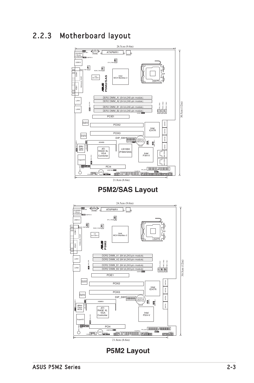
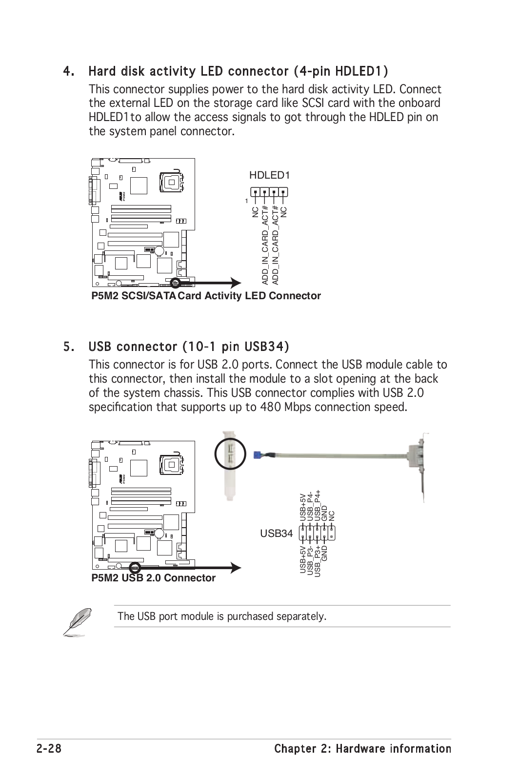
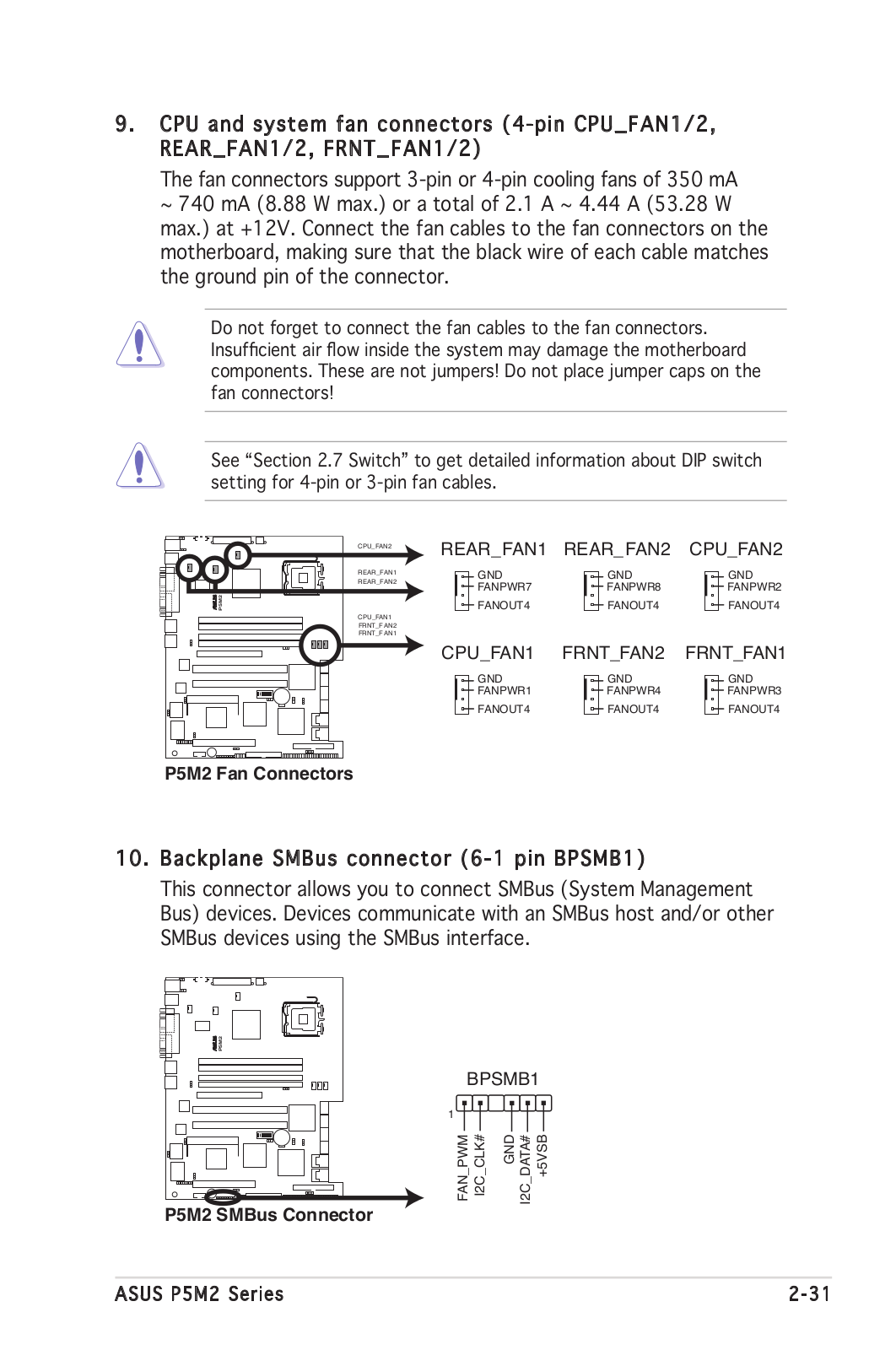
P5M2
3
P5M2-E
2
P5M2-E/4L
2
P5M2-M
2
P5M2-M/C
P5M2P-E4L
2
P5M2/SAS
2
P5MT
2
P5MT-C
P5MT-M
2
P5MT-MX-C
2
P5MT-S
2
P5N32-E SLI
5
P5N32-E SLI Plus
6
P5N32-SLI
5
P5N32-SLI Deluxe
4
P5N32-SLI DLX
P5N32-SLI PR
P5N32-SLI PREMIUM
5
P5N32-SLI SE
2
P5N32-SLI SE DELUXE
3
P5N32-SLI SE DLX
P5N64 WS
P5N64 WS Pro
P5N64 WS PROFESSIONAL
P5N72-T
2
P5N72-T PREMIUM
4
P5N73-AM
10
P5N73-CM
11
P5N7A-VM
5
P5N-D
6
P5ND2
2
P5ND2-SE
5
P5ND2-SLI
4
P5ND2-SLI DELUXE
2
P5N-EM
5
P5N-EM HDMI
2
P5N-E SLI
7
P5N-E SLI GREEN
P5N-MX
7
P5NSLI
6
P5N-T
2
P5N-T Deluxe
10
P5NT WS
6
P5NT WS Pro
P5N-VM WS
2
P5P41C
7
P5P41D
7
P5P41T
6
P5P41TD
5
P5P41T LE
8
P5P41T PLUS
2
P5P41T-USB3
3
p5p43t
P5P43TD
6
Loading...
Loading...
Nothing found
P5M2/SAS
User’s Manual
189 pgs
5.76 Mb
0
User’s Manual
181 pgs
8.21 Mb
0
Table of contents
Loading...
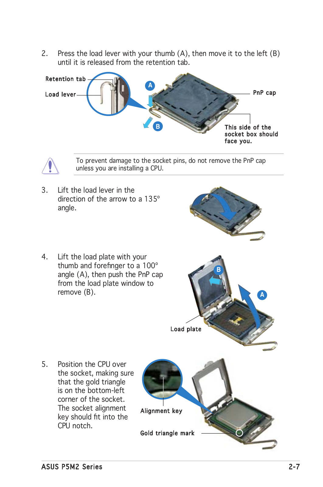
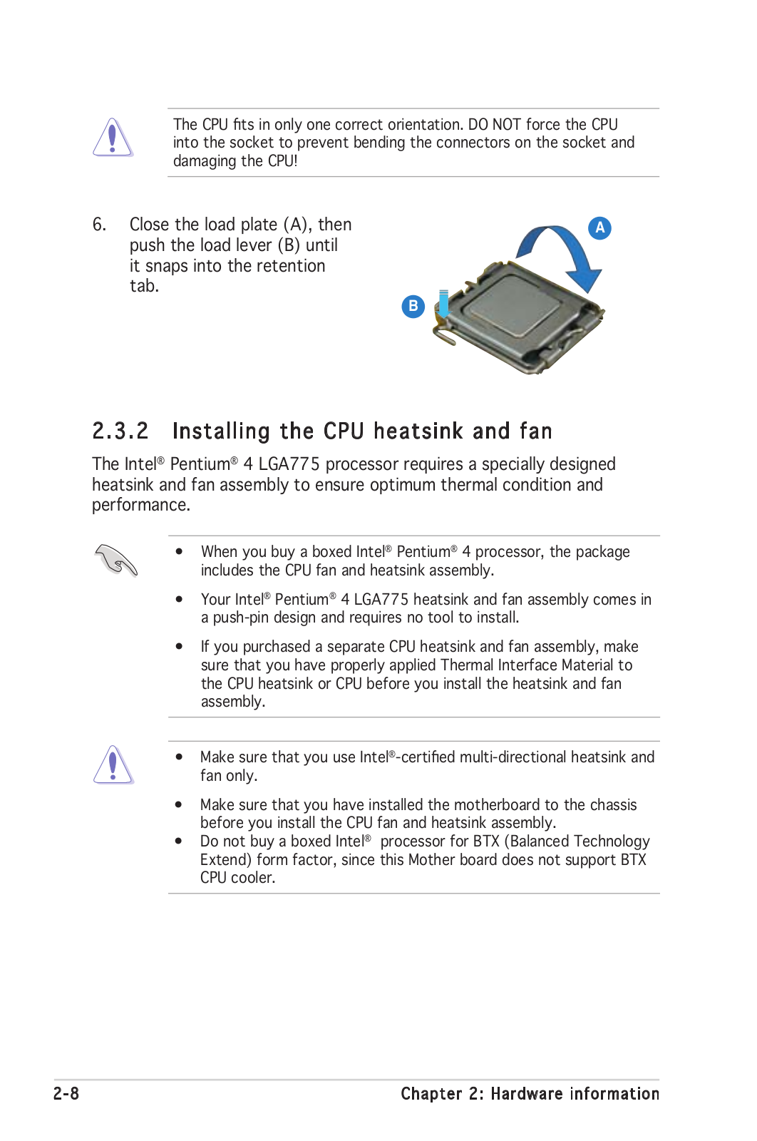
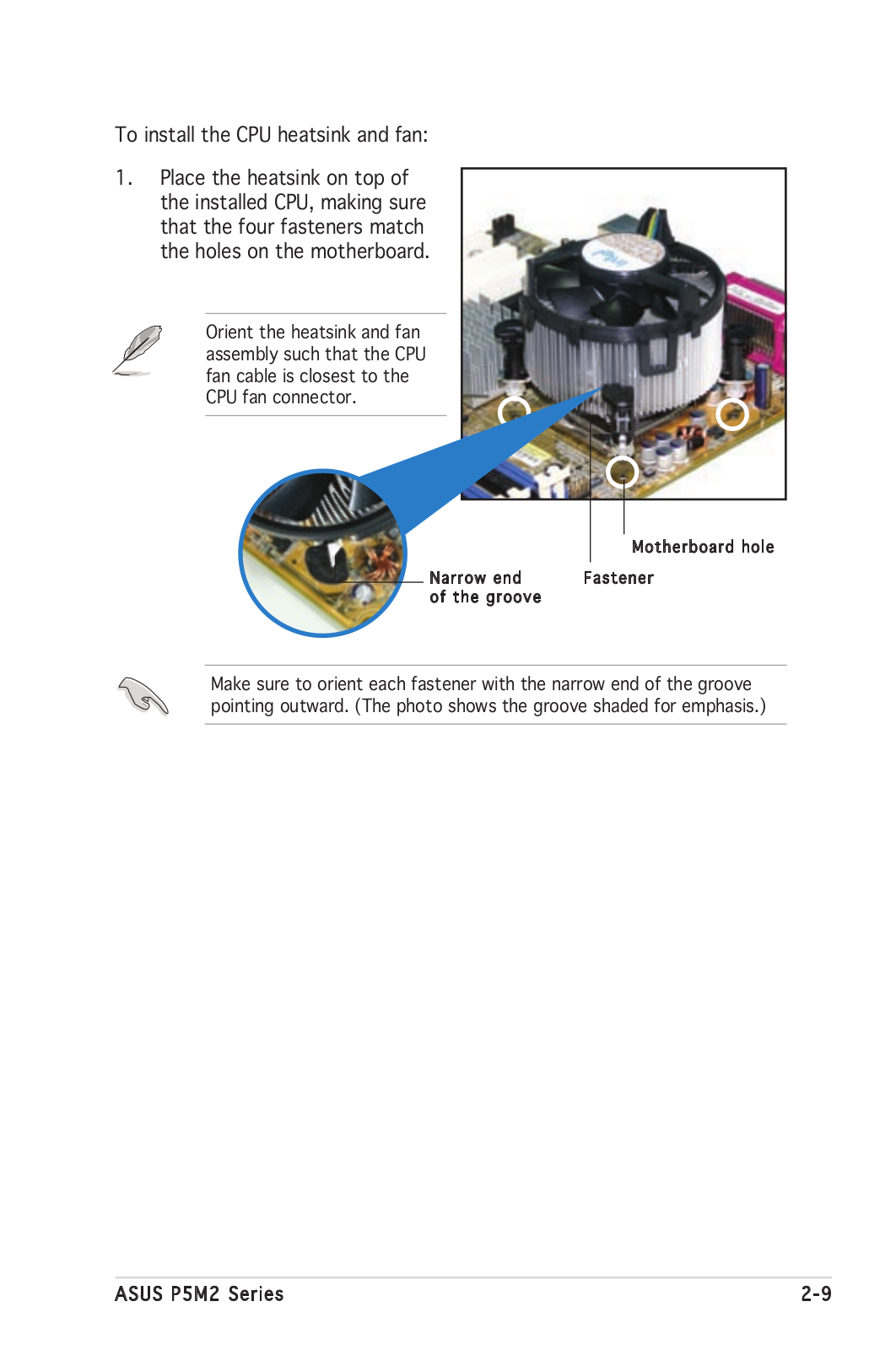
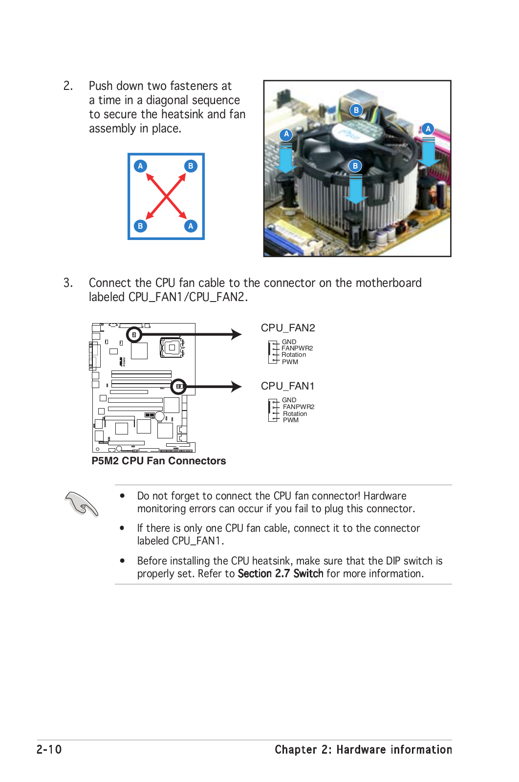
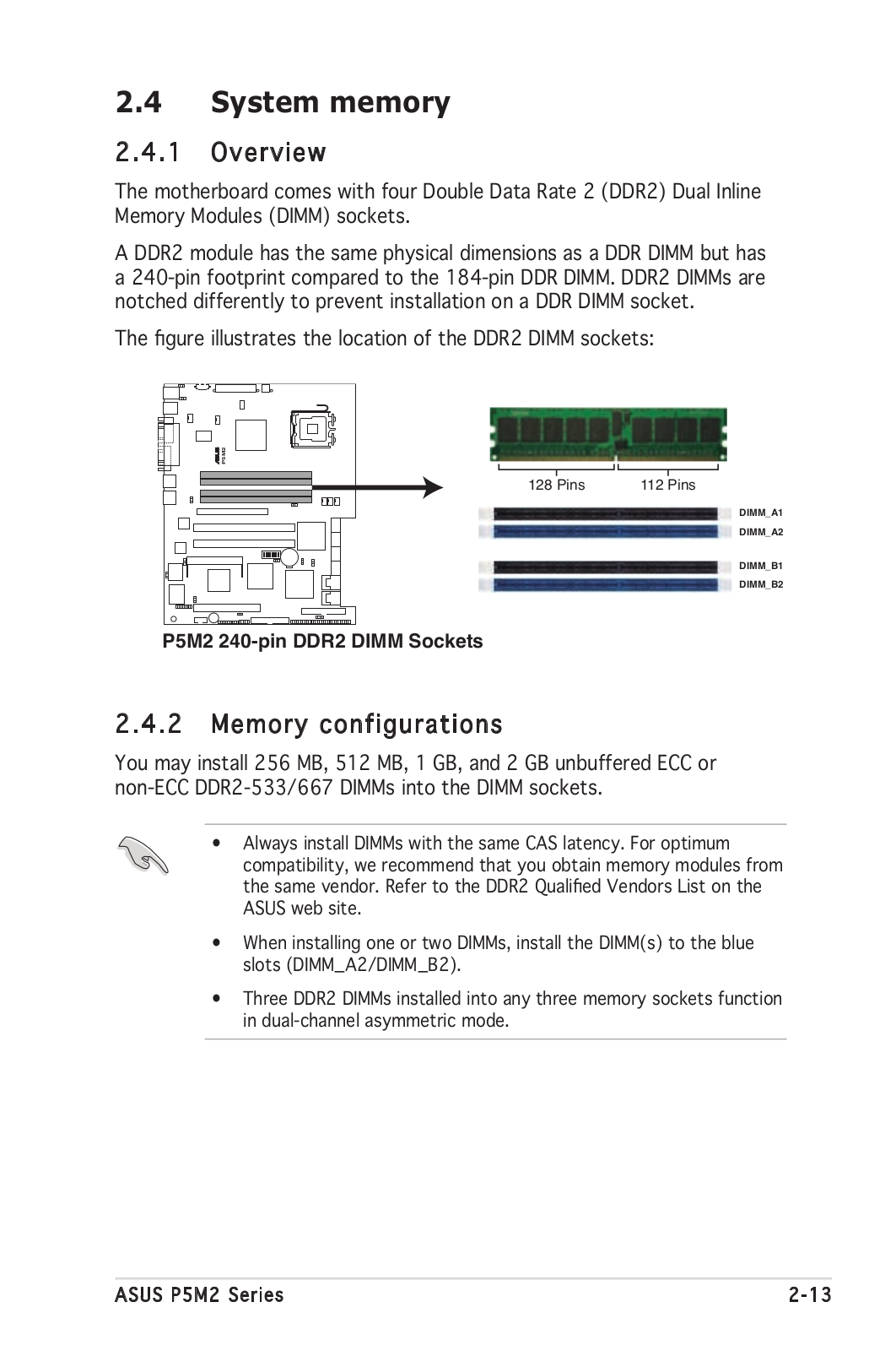
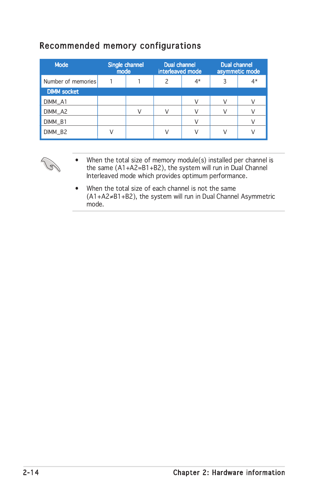
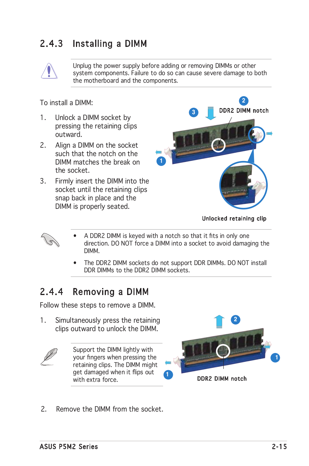
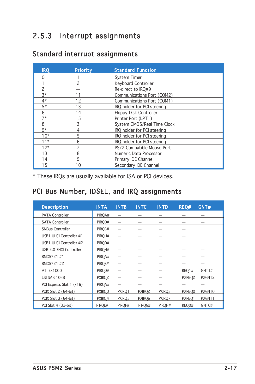
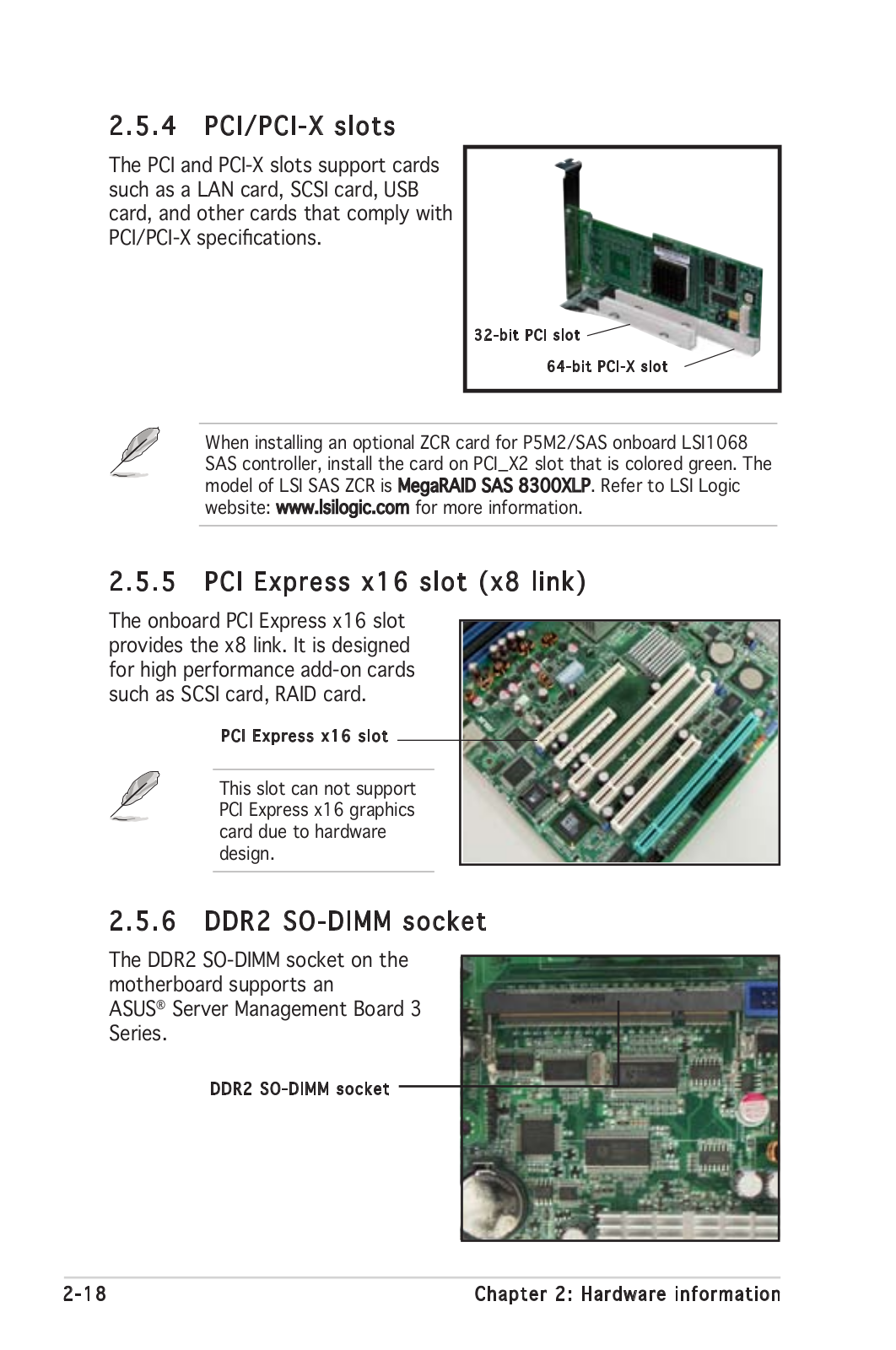
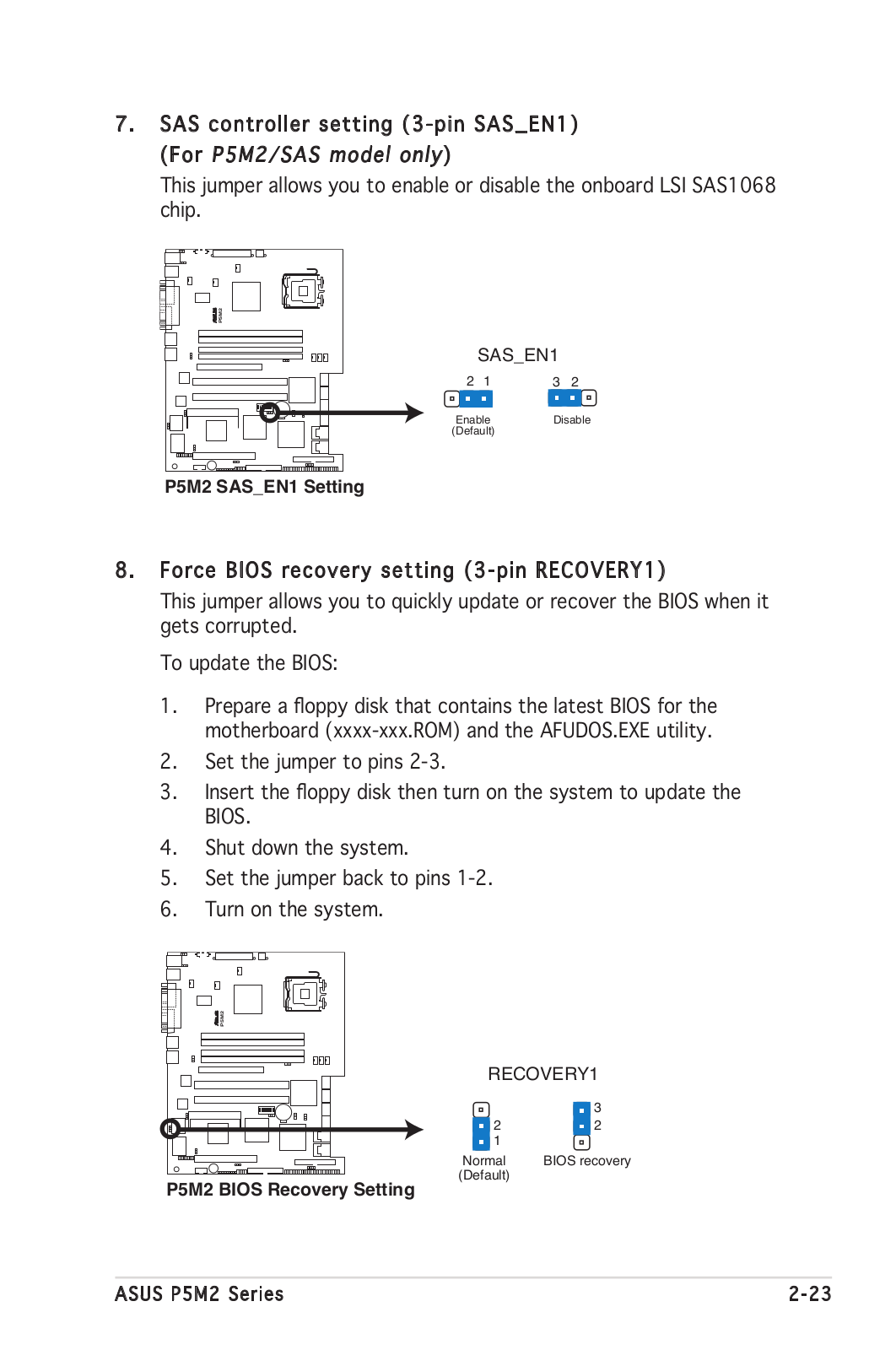
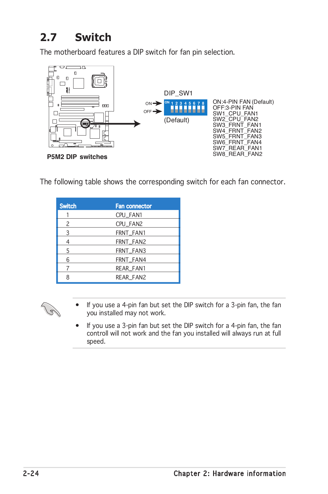
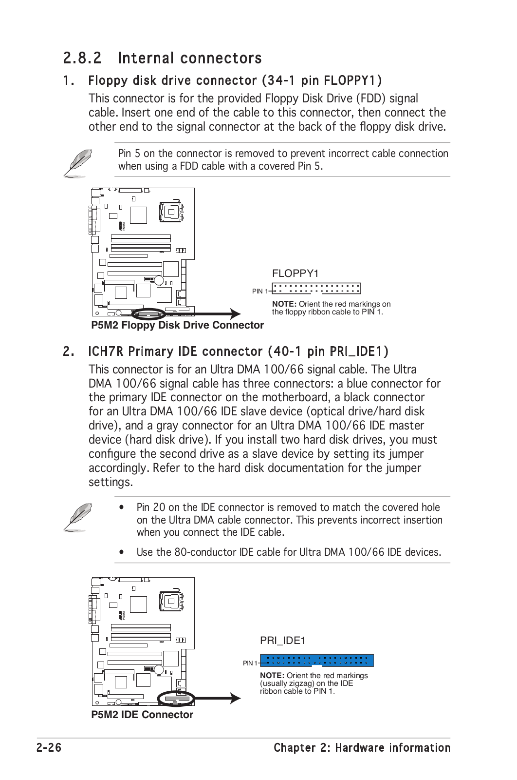
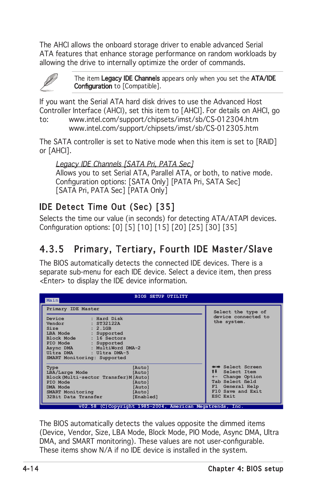
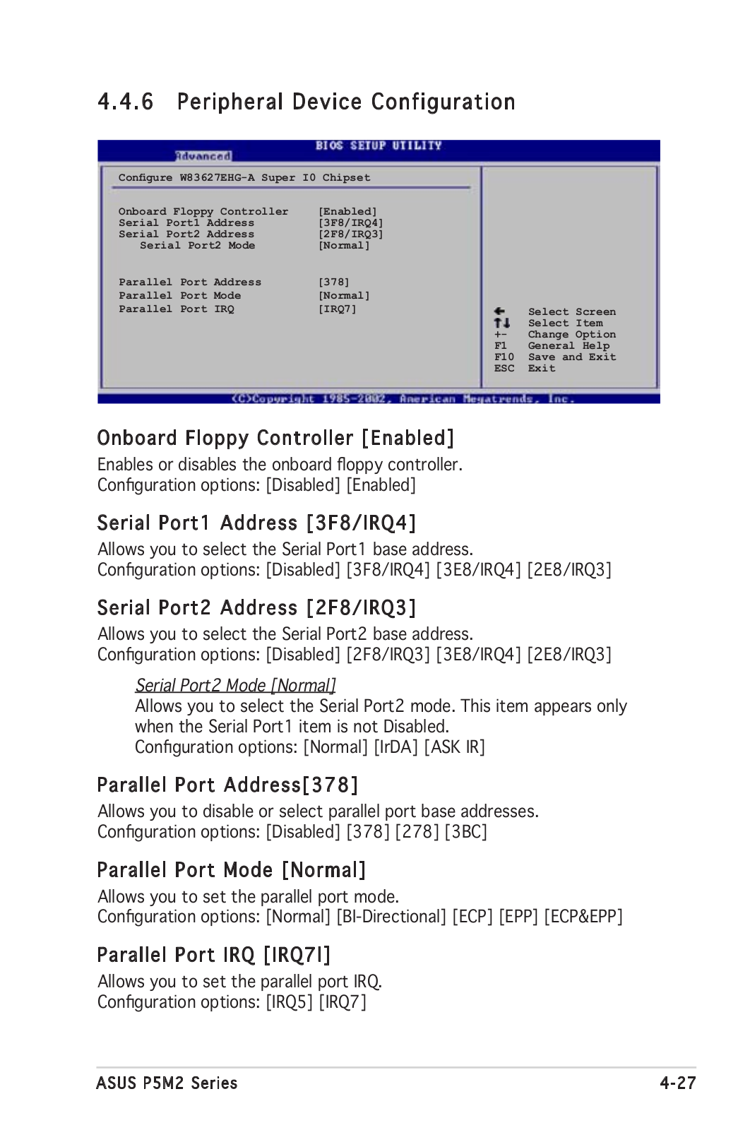
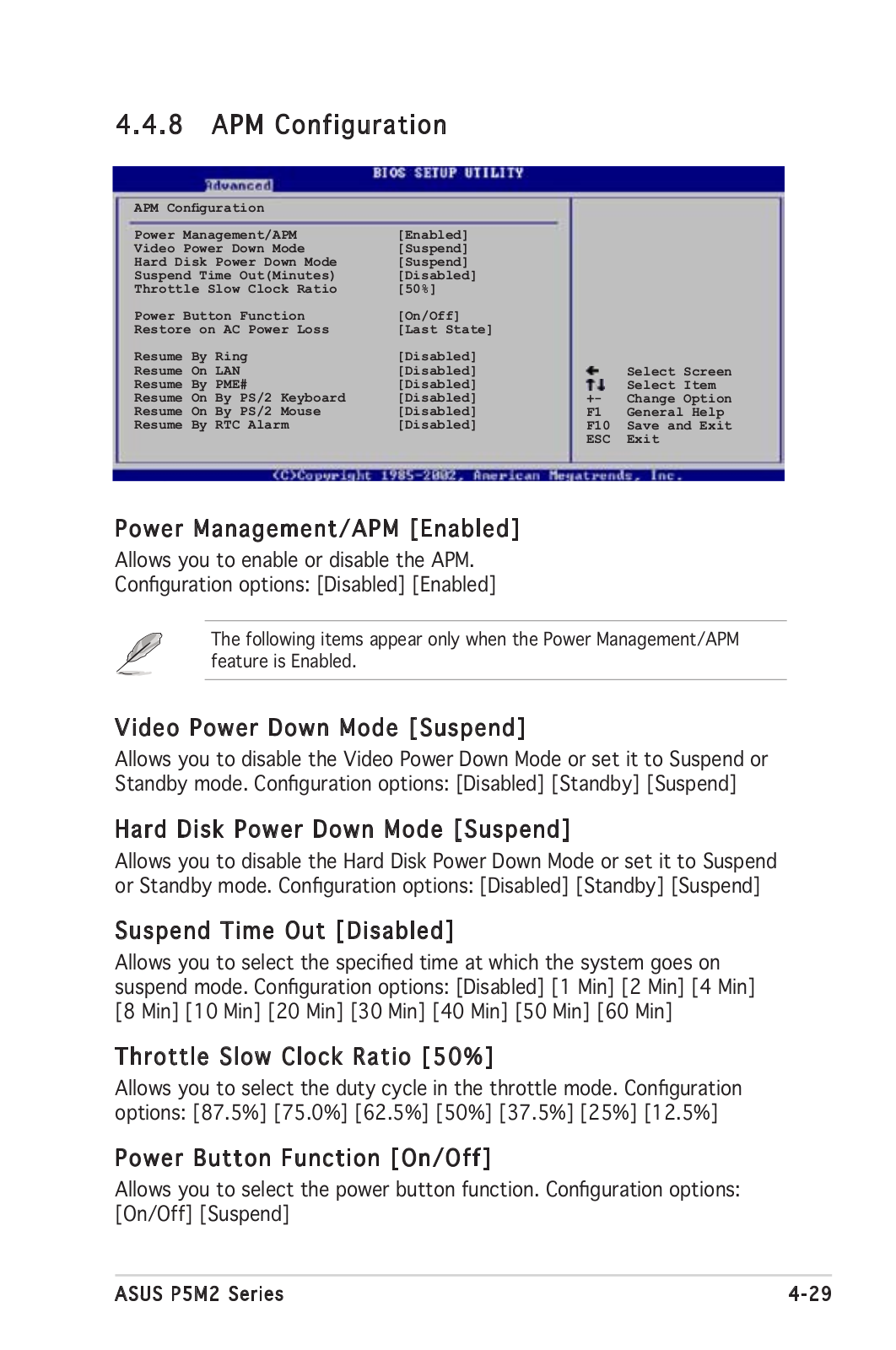
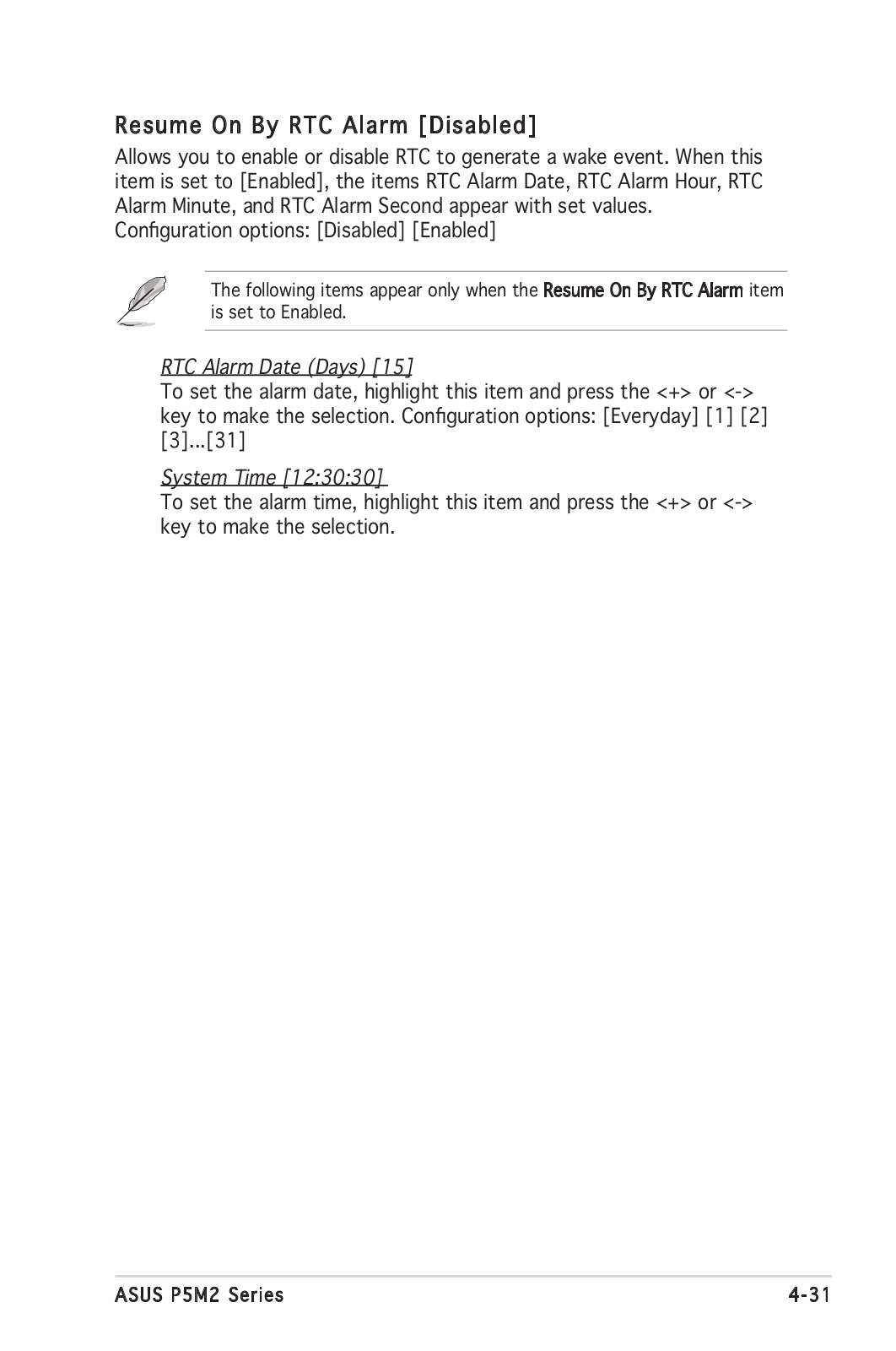
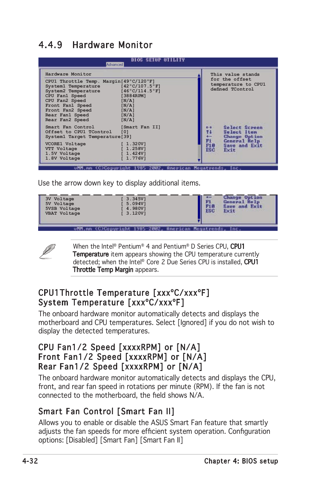
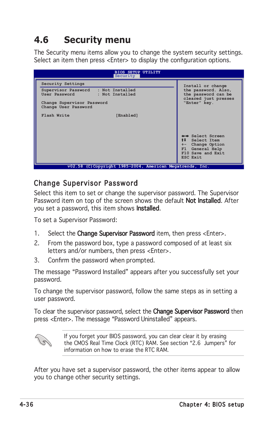
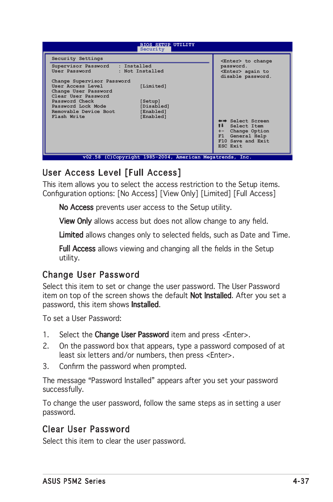
Asus P5M2/SAS, P5M2 User’s Manual
...
Asus User’s Manual
Download
Specifications and Main Features
Frequently Asked Questions
User Manual
Download
Loading...
+
hidden pages
Unhide
You need points to download manuals.
1 point = 1 manual.
You can buy points or you can get point for every manual you upload.
Buy points
Upload your manuals
 Loading...