


Asus P5G41-M EVO User Manual

P5G41-M EVO
Motherboard

E4899
First Edition V1
August 2009
Copyright © 2009 ASUSTeK Computer Inc. All Rights Reserved.
No part of this manual, including the products and software described in it, may be reproduced,
transmitted, transcribed, stored in a retrieval system, or translated into any language in any form or by any
means, except documentation kept by the purchaser for backup purposes, without the express written
permission of ASUSTeK Computer Inc. (“ASUS”).
Product warranty or service will not be extended if: (1) the product is repaired, modied or altered, unless
such repair, modication of alteration is authorized in writing by ASUS; or (2) the serial number of the
product is defaced or missing.
ASUS PROVIDES THIS MANUAL “AS IS” WITHOUT WARRANTY OF ANY KIND, EITHER EXPRESS
OR IMPLIED, INCLUDING BUT NOT LIMITED TO THE IMPLIED WARRANTIES OR CONDITIONS OF
MERCHANTABILITY OR FITNESS FOR A PARTICULAR PURPOSE. IN NO EVENT SHALL ASUS, ITS
DIRECTORS, OFFICERS, EMPLOYEES OR AGENTS BE LIABLE FOR ANY INDIRECT, SPECIAL,
INCIDENTAL, OR CONSEQUENTIAL DAMAGES (INCLUDING DAMAGES FOR LOSS OF PROFITS,
LOSS OF BUSINESS, LOSS OF USE OR DATA, INTERRUPTION OF BUSINESS AND THE LIKE),
EVEN IF ASUS HAS BEEN ADVISED OF THE POSSIBILITY OF SUCH DAMAGES ARISING FROM ANY
DEFECT OR ERROR IN THIS MANUAL OR PRODUCT.
SPECIFICATIONS AND INFORMATION CONTAINED IN THIS MANUAL ARE FURNISHED FOR
INFORMATIONAL USE ONLY, AND ARE SUBJECT TO CHANGE AT ANY TIME WITHOUT NOTICE,
AND SHOULD NOT BE CONSTRUED AS A COMMITMENT BY ASUS. ASUS ASSUMES NO
RESPONSIBILITY OR LIABILITY FOR ANY ERRORS OR INACCURACIES THAT MAY APPEAR IN THIS
MANUAL, INCLUDING THE PRODUCTS AND SOFTWARE DESCRIBED IN IT.
Products and corporate names appearing in this manual may or may not be registered trademarks or
copyrights of their respective companies, and are used only for identication or explanation and to the
owners’ benet, without intent to infringe.
ii

Contents
Notices .......................................................................................................... v
Safety information ...................................................................................... vi
Safety information ..................................................................................... vii
P5G41-M EVO specications summary .................................................. viii
Chapter 1: Product introduction
1.1 Before you proceed ..................................................................... 1-1
1.2 Motherboard overview ................................................................. 1-2
1.2.1 Motherboard layout ......................................................... 1-2
1.2.2 Layout contents ............................................................... 1-2
1.3 Central Processing Unit (CPU) ................................................... 1-3
1.4 System memory ........................................................................... 1-3
1.4.1 Overview ......................................................................... 1-3
1.4.2 Memory congurations .................................................... 1-4
1.5 Expansion slots ............................................................................ 1-7
1.5.1 Installing an expansion card ........................................... 1-7
1.5.2 Conguring an expansion card ....................................... 1-8
1.5.3 PCI slots .......................................................................... 1-8
1.5.4 PCI Express x16 slot ....................................................... 1-8
1.6 Jumpers ........................................................................................ 1-8
1.7 Connectors ................................................................................. 1-10
1.7.1 Rear panel ports ........................................................... 1-10
1.7.2 Internal connectors ........................................................1-11
1.8 Software support ........................................................................ 1-18
1.8.1 Installing an operating system ...................................... 1-18
1.8.2 Support DVD information .............................................. 1-18
Chapter 1: BIOS information
2.1 Managing and updating your BIOS ............................................ 2-1
2.1.1 ASUS Update utility ........................................................ 2-1
2.1.2 ASUS EZ Flash 2 utility ................................................... 2-2
2.1.3 ASUS CrashFree BIOS ................................................... 2-3
2.2 BIOS setup program .................................................................... 2-4
2.3 Main menu .................................................................................... 2-4
iii

Contents
2.3.1 System Time .................................................................. 2-5
2.3.2 System Date .................................................................. 2-5
2.3.3 Legacy Diskette A .......................................................... 2-5
2.3.4 Primary IDE Master/Slave and SATA 1-4................................2-5
2.3.6 System Information ......................................................... 2-6
2.3.5 Storage Conguration ..................................................... 2-6
2.4 Advanced menu ........................................................................... 2-7
2.4.1 CPU Conguration .......................................................... 2-7
2.4.2 Chipset ............................................................................ 2-8
2.4.3 Onboard Devices Conguration ...................................... 2-9
2.4.4 USB Conguration .......................................................... 2-9
2.4.5 PCI PnP ........................................................................ 2-10
2.5 Power menu ................................................................................ 2-11
2.5.1 Suspend Mode ..............................................................2-11
2.5.2 ACPI 2.0 Support ...........................................................2-11
2.5.3 ACPI APIC Support .......................................................2-11
2.5.4 APM Conguration .........................................................2-11
2.5.5 Hardware Monitor ......................................................... 2-12
2.6 Boot menu .................................................................................. 2-13
2.6.1 Boot Device Priority ...................................................... 2-13
2.6.2 Boot Settings Conguration .......................................... 2-13
2.6.3 Security ......................................................................... 2-14
2.7 Tools menu ................................................................................. 2-15
2.7.1 ASUS EZ Flash 2 .......................................................... 2-15
2.7.2 AI NET 2........................................................................ 2-15
2.8 Exit menu .................................................................................... 2-16
iv
Notices
Federal Communications Commission Statement
This device complies with Part 15 of the FCC Rules. Operation is subject to the following two
conditions:
•
This device may not cause harmful interference, and
•
This device must accept any interference received including interference that may cause
undesired operation.
This equipment has been tested and found to comply with the limits for a Class B digital
device, pursuant to Part 15 of the FCC Rules. These limits are designed to provide
reasonable protection against harmful interference in a residential installation. This
equipment generates, uses and can radiate radio frequency energy and, if not installed
and used in accordance with manufacturer’s instructions, may cause harmful interference
to radio communications. However, there is no guarantee that interference will not occur
in a particular installation. If this equipment does cause harmful interference to radio or
television reception, which can be determined by turning the equipment off and on, the user
is encouraged to try to correct the interference by one or more of the following measures:
•
Reorient or relocate the receiving antenna.
•
Increase the separation between the equipment and receiver.
•
Connect the equipment to an outlet on a circuit different from that to which the receiver is
connected.
•
Consult the dealer or an experienced radio/TV technician for help.
The use of shielded cables for connection of the monitor to the graphics card is required
to assure compliance with FCC regulations. Changes or modications to this unit not
expressly approved by the party responsible for compliance could void the user’s authority
to operate this equipment.
Canadian Department of Communications Statement
This digital apparatus does not exceed the Class B limits for radio noise emissions from
digital apparatus set out in the Radio Interference Regulations of the Canadian Department
of Communications.
This class B digital apparatus complies with Canadian ICES-003.
REACH
Complying with the REACH (Registration, Evaluation, Authorisation, and Restriction of
Chemicals) regulatory framework, we published the chemical substances in our products at
ASUS REACH website at http://green.asus.com/english/REACH.htm.
DO NOT throw the motherboard in municipal waste. This product has been designed to
enable proper reuse of parts and recycling. This symbol of the crossed out wheeled bin
indicates that the product (electrical and electronic equipment) should not be placed in
municipal waste. Check local regulations for disposal of electronic products.
DO NOT throw the mercury-containing button cell battery in municipal waste. This symbol
of the crossed out wheeled bin indicates that the battery should not be placed in municipal
waste.
v
Safety information
Electrical safety
• To prevent electric shock hazard, disconnect the power cable from the electric outlet
before relocating the system.
•
When adding or removing devices to or from the system, ensure that the power cables
for the devices are unplugged before the signal cables are connected. If possible,
disconnect all power cables from the existing system before you add a device.
•
Before connecting or removing signal cables from the motherboard, ensure that all
power cables are unplugged.
•
Seek professional assistance before using an adapter or extension cord. These devices
could interrupt the grounding circuit.
• Ensure that your power supply is set to the correct voltage in your area. If you are not
sure about the voltage of the electrical outlet you are using, contact your local power
company.
• If the power supply is broken, do not try to x it by yourself. Contact a qualied service
technician or your retailer.
• The optical S/PDIF is an optional component (may or may not be included in your
motherboard) and is dened as a CLASS 1 LASER PRODUCT.
INVISIBLE LASER RADIATION, AVOID EXPOSURE TO BEAM.
• Never dispose of the battery in re. It could explode and release harmful substances into
the environment.
• Never dispose of the battery with your regular household waste. Take it to a hazardous
material collection point.
• Never replace the battery with an incorrect battery type.
Operation safety
•
Before installing the motherboard and adding devices on it, carefully read all the manuals
that came with the package.
•
Before using the product, ensure that all cables are correctly connected and the power
cables are not damaged. If you detect any damage, contact your dealer immediately.
•
To avoid short circuits, keep paper clips, screws, and staples away from connectors,
slots, sockets and circuitry.
•
Avoid dust, humidity, and temperature extremes. Do not place the product in any area
where it may become wet.
•
Place the product on a stable surface.
•
If you encounter technical problems with the product, contact a qualied service
technician or your retailer.
vi
• RISK OF EXPLOSION IF BATTERY IS REPLACED BY AN INCORRECT TYPE.
• DISPOSE OF USED BATTERIES ACCORDING TO THE ABOVE BATTERY-RELATED
INSTRUCTIONS.
This motherboard should only be used in environments with ambient temperatures between
5℃ (14℉) and 40℃ (104℉).
Safety information
Electrical safety
•
To prevent electrical shock hazard, disconnect the power cable from the electrical outlet
before relocating the system.
•
When adding or removing devices to or from the system, ensure that the power cables
for the devices are unplugged before the signal cables are connected. If possible,
disconnect all power cables from the existing system before you add a device.
•
Before connecting or removing signal cables from the motherboard, ensure that all
power cables are unplugged.
•
Seek professional assistance before using an adpater or extension cord. These devices
could interrupt the grounding circuit.
• Make sure that your power supply is set to the correct voltage in your area. If you are
Where to nd more information
Refer to the following sources for additional information and for product and software
updates.
1. ASUS websites
The ASUS website provides updated information on ASUS hardware and software
products. Refer to the ASUS contact information.
2. Optional documentation
Your product package may include optional documentation, such as warranty yers,
that may have been added by your dealer. These documents are not part of the
standard package.
Conventions used in this guide
To make sure that you perform certain tasks properly, take note of the following symbols used
throughout this manual.
DANGER/WARNING: Information to prevent injury to yourself when trying to
complete a task.
CAUTION: Information to prevent damage to the components when trying to
complete a task.
IMPORTANT: Instructions that you MUST follow to complete a task.
NOTE: Tips and additional information to help you complete a task.
Typography
Bol d tex t Indicates a menu or an item to select.Indicates a menu or an item to select.
Italics
Used to emphasize a word or a phrase.
<Key> Keys enclosed in the less-than and greater-than sign means
that you must press the enclosed key.
Example: <Enter> means that you must press the Enter or
Return key.
<Key1>+<Key2>+<Key3> If you must press two or more keys simultaneously, the key
names are linked with a plus sign (+).
Example: <Ctrl>+<Alt>+<D>
vii

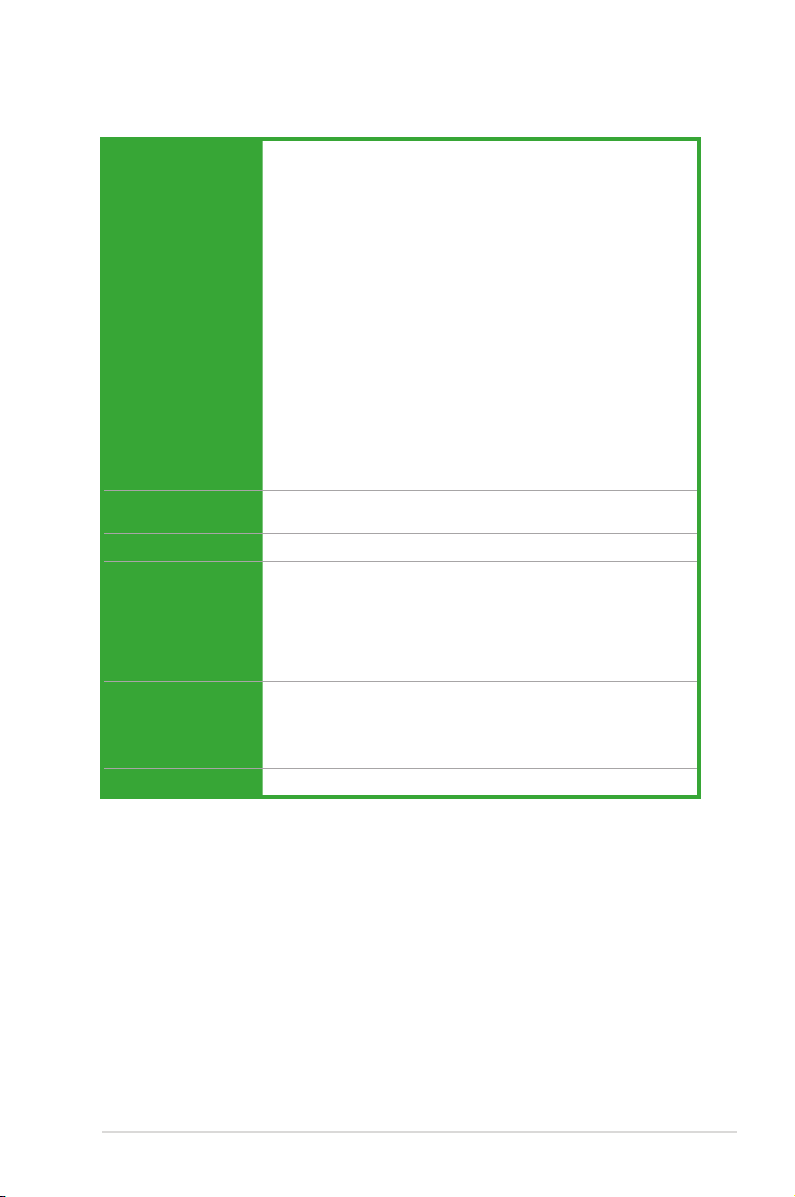
P5G41-M EVO specications summary
CPU LGA775 Socket for Intel® Core�2 Extreme /Core�2 Quad /Core�2 Extreme /Core�2 Quad /Core�2 Quad /
Chipset Northbridge: Intel® G41
System bus 1333/1066/800MHz
Memory Dual-channel memory architecture
Expansion slots 1 x PCI Express x16 slot
Storage Southbridge Intel® ICH7 supports:
LAN Realtek® 8112L PCIe Gb LAN controller
Audio VT1708S High Denition Audio 6-channel CODEC
USB 8 x USB 2.0/1.1 ports (4 ports at mid-board, 4 ports at back
ASUS Special
features
Rear panel ports 1 x PS/2 keyboard port
Core�2 Duo / Pentium® dual-core / Celeron® dual-core /
Celeron® processors
Supports Intel® 45nm multi-core CPU
Intel® Hyper-Threading Technology ready
Support Enhanced Intel SpeedStep Technology (EIST)
* Ensure that you use a supported CPU, otherwise the system
will show a warning message and automatically shutdown.
Southbridge: Intel® ICH7
- 4 x 240-pin DIMM sockets support unbuffered non-ECC
DDR2 800/667MHz memory modules
- Supports up to 8GB system memory
** When you install a total memory of 4GB capacity or more,
Windows® 32-bit operating system may only recognize less
than 3GB. We recommend a maximum of 3GB system
memory if you are using a Windows® 32-bit OS.
3 x PCI slots
Support PCIe 1.1 Architecture
4 x Serial ATA 3Gb/s connectors
1 x UltraDMA 100/66 connector
Supports Multi-Streaming
panel)
ASUS CrashFree BIOS 3
ASUS EZ Flash2
ASUS AI NET2
ASUS MyLogo 2
ASUS Q-Fan
1 x PS/2 mouse port
1 x LAN (RJ-45) port
4 x USB 2.0/1.1 ports
6-channel audio I/O port
1 x VGA port
1 x DVI port
1 x HDMI port
1 x COM port
(continued on the next page)
viii
P5G41-M EVO specications summary
Internal connectors 1 x High Denition front panel audio connector
1 x S/PDIF out connector
1 x System panel connector
2 x USB 2.0 connectors support additional 4 USB 2.0 ports
1 x CPU fan connector
1 x Chassis fan connector
1 x CD audio-in connector
1 x 24-pin EATX Power connector
1 x 4-pin ATX 12V Power connector
4 x SATA connectors
1 x COM connector
1 x IDE connector
1 x LPT connector
1 x Floppy connector
1 x Chassis intrusion connector
1 x IEEE1394a connector
BIOS features 8 Mb Flash ROM, AMI BIOS, PnP, DMI v2.0, WfM2.0, SMBIOS
Manageability WOL, PXE, WOR by Ring, PME Wake Up
Accessories 1 x UltraDMA 100/66 cable
Support DVD Drivers
Form factor MicroATX form factor: 9.6 in x 9.6 in (24.4 cm x 24.4cm)
v2.5, ACPI v2.0a
2 x Serial ATA cables
1 x 1394 cable
1 x Printer port cable
1 x I/O shield
User Manual
ASUS Update
ASUS PC Probe II
Anti-virus software (OEM version)
*Specications are subject to change without notice.
ix

x
Chapter 1
P5G41-M EVO
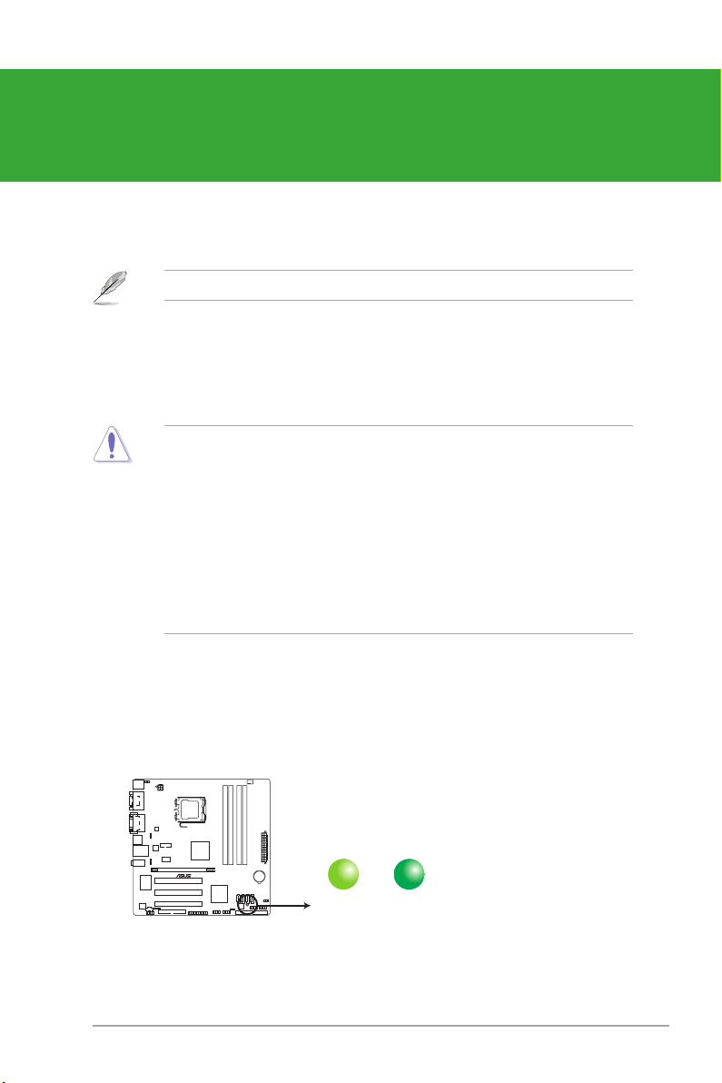
SB_PWR
ON
Standby Power Powered Off
OFF
P5G41-M EVO Onboard LED
Product introduction
Thank you for buying an ASUS® P5G41-M EVO motherboard!
Before you start installing the motherboard, and hardware devices on it, check the items in
your motherboard package. Refer to page ix for the list of accessories.
If any of the items is damaged or missing, contact your retailer.
1.1 Before you proceed
Take note of the following precautions before you install motherboard components or change
any motherboard settings.
• Unplug the power cord from the wall socket before touching any component.
• Before handling components, use a grounded wrist strap or touch a safely grounded
object or a metal object, such as the power supply case, to avoid damaging them due to
static electricity
• Hold components by the edges to avoid touching the ICs on them.
• Whenever you uninstall any component, place it on a grounded antistatic pad or in the
bag that came with the component.
• Before you install or remove any component, switch off the ATX power supply and
detach its power cord. Failure to do so may cause severe damage to the motherboard,
peripherals, or components.
Onboard LED
This motherboard comes with a standby power LED that lights up to indicate that the system
is ON, in sleep mode, or in soft-off mode. This is a reminder that you must shut down
the system and unplug the power cable before removing or plugging in any motherboard
component. The illustration below shows the location of the onboard LED.
ASUS P5G41-M EVO 1-1
1.2 Motherboard overview
P5G41-M EVO
PCIEX16
PCI2
PCI3
PCI1
PRI_IDE
LPT
USB56 USB78
SPDIF_OUT
AAFP
ICS
9LPRS441
ATX12V
EATXPWR
CPU_FAN
COM1
Intel
®
G41
Lithium Cell
CMOS Power
Super
I/O
AUDIO
VIA
VT1708S
RTL
8112L
KBMS
8Mb
BIOS
SB_PWR
F_PANEL
CLRTC
KBPWR
24.4cm(9.6in)
24.4cm(9.6in)
LGA775
Intel
®
ICH7
DDR2 DIMM_A1 (64bit, 240-pin module)
DDR2 DIMM_A2 (64bit, 240-pin module)
DDR2 DIMM_B1 (64bit, 240-pin module)
DDR2 DIMM_B2 (64bit, 240-pin module)
HDMI
COM1
LAN1_USB12
USB34
SATA1SATA2SATA3SATA4
IE1394_1
FLOPPY
DVI_VGA
CD
CHA_FAN
USBPW1-4
CHASSIS
USBPW5-8
321 7 44 5 6
8
2
10
9
11
3
14 12131617181920 15
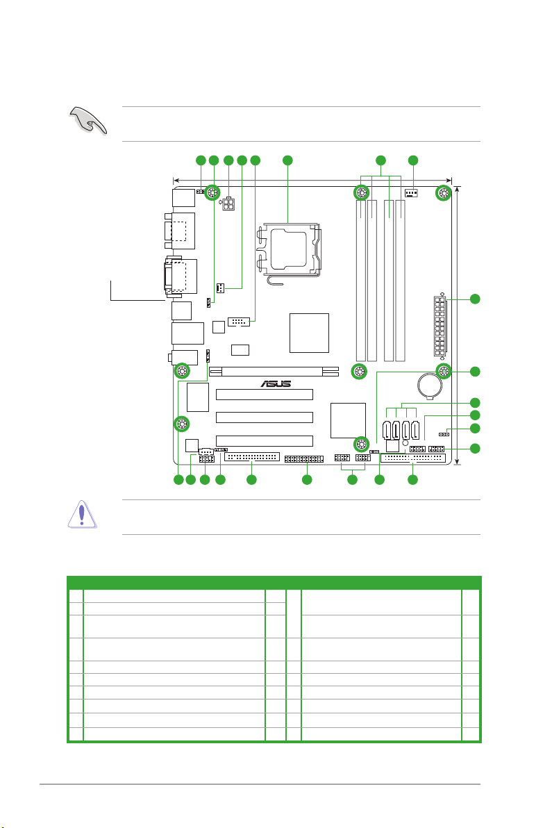
1.2.1 Motherboard layout
Ensure that you install the motherboard into the chassis in the correct orientation. The edge
with external ports goes to the rear part of the chassis.
Place this side towards
the rear of the chassis.
1.2.2 Layout contents
Place eight screws into the holes indicated by circles to secure the motherboard to the
chassis. DO NOT overtighten the screws! Doing so can damage the motherboard.
Connectors/Jumpers/Slots/LED Page Connectors/Jumpers/Slots/LED
1. Keyboard power (3-pin KBPWR) 1-9 11. IEEE 1394a connector (10-1 pin IE1394_1) 1-17
2. USB device wake-up (3-pin USBPW1-4, USBPW5-8) 1-9 12. IDE connector (40-1 pin PRI_IDE) 1-12
3. ATX power connectors (24-pin EATXPWR, 4-pin
4. CPU and Chassis fan connectors (4-pin CPU_FAN,
5. Serial port connectors (10-1 pin COM1) 1-13 15. LPT connector (26-1 pin LPT) 1-17
6. Intel CPU socket 1-3 16 Floppy disk drive connector (34-1 pin FLOPPY) 1-17
7. DDR2 DIMM sockets 1-3 17. Digital audio connector (4-1 pin SPDIF_OUT) 1-15
8. Serial ATA connectors (7-pin SATA1-4) 1-12 18. Front panel audio connector (10-1 pin AAFP) 1-16
9. System panel connector (10-1 pin F_PANEL) 1-15 19. Optical drive audio in connector (4-pin CD) 1-14
10. Clear RTC RAM (3-pin CLRTC) 1-8 20. Chassis intrusion connector (4-1 pin CHASSIS) 1-16
1-2 Chapter 1: Product introduction
ATX12V)
3-pin CHA_FAN)
1-14 13. Onboard LED 1-1
1-11 14. USB connectors (10-1 pin USB56, USB78) 1-13
1.3 Central Processing Unit (CPU)
P5G41-M EVO
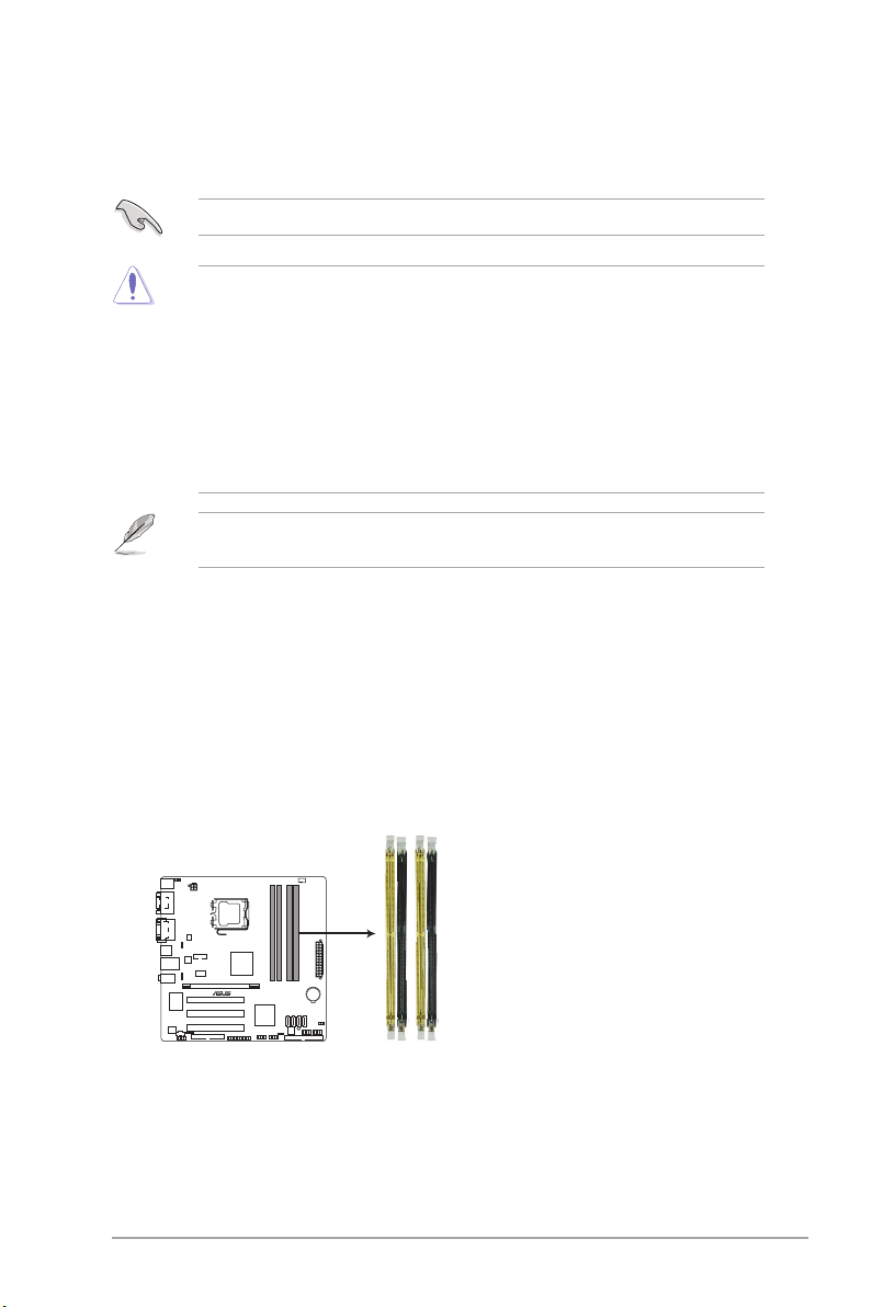
P5G41-M EVO 240-pin DDR2 DIMM sockets
DIMM_A1
DIMM_A2
DIMM_B1
DIMM_B2
This motherboard comes with a surface mount LGA775 socket designed for the Intel® Core�
2 Quad / Core�2 Exreme / Core�2 Duo / Pentium® dual-core / Celeron® dual-core /
Celeron® processors.
Ensure that all power cables are unplugged before installing the CPU.
• Upon purchase of the motherboard, ensure that the PnP cap is on the socket and the
socket contacts are not bent. Contact your retailer immediately if the PnP cap is missing,
or if you see any damage to the PnP cap/socket contacts/motherboard components.
ASUS will shoulder the cost of repair only if the damage is shipment/transit-related.
• Keep the cap after installing the motherboard. ASUS will process Return Merchandise
Authorization (RMA) requests only if the motherboard comes with the cap on the
LGA775 socket.
• The product warranty does not cover damage to the socket contacts resulting from
incorrect CPU installation/removal, or misplacement/loss/incorrect removal of the PnP
cap.
This motherboard supports Intel® Hyper-Threading Technology and Enhanced Intel
SpeedStep® Technology (EIST).
1.4 System memory
1.4.1 Overview
This motherboard comes with four Double Data Rate 2 (DDR2) Dual Inline Memory Module
(DIMM) sockets. A DDR2 DIMM has the same physical dimensions as a DDR DIMM but
has a 240-pin footprint compared to the 184-pin DDR DIMM. DDR2 DIMMs are notched
differently to prevent installation on a DDR DIMM socket. The gure illustrates the location of
the DDR2 DIMM sockets:
ASUS P5G41-M EVO 1-3
1.4.2 Memory congurations
You may install a 512MB, 1GB, and 2GB unbuffered non-ECC DDR2 DIMM into the DIMM
socket.
• You may install varying memory sizes in Channel A and Channel B. The system maps
the total size of the lower-sized channel for the dual-channel conguration. Any excess
memory from the higher-sized channel is then mapped for single-channel operation.
• For dual-channel conguration, you can:
- install two identical DIMMs in DIMM_A1 and DIMM_B1; or
- install four identical DIMMs in all four slots; or
- install one identical DIMM pair in DIMM_A1 and DIMM_B1 (yellow slots) and
another identical DIMM pair in DIMM_A2 and DIMM_B2 (black slots).
• Due to the memory address limitation on the 32-bit Windows® OS, when you install
4GB or more memory on the motherboard, the actual usable memory for the OS can be
about 3GB or less. For effective use of memory, we recommend that you do either of the
following:
- Install a maximum of 3GB system memory if you are using a 32-bit Windows
OS.
- Use a 64-bit Windows® OS if you want to install 4GB or more memory on the
motherboard.
• This motherboard does not support DIMMs made up of 256 megabits (Mb) chips or less.
• This motherboard supports up to 8GB on Windowsindows® XP Professional x64 and Windows®
Vista x64 editions. You may install a maximum of 2GB DIMMs on each slot.. You may install a maximum of 2GB DIMMs on each slot.
• The default memory operation frequency is dependent on its Serial Presence Detect
(SPD), which is the standard way of accessing information from a memory module.
Under the default state, some memory modules for overclocking may operate at a lower
frequency than the vendor-marked value.
• For system stability, use a more efcient cooling system to support a full memory load (4
DIMMs) or overclocking conditions.
®
P5G41-M EVO Motherboard Qualied Vendors List (QVL)
DDR2-800MHz capability
Voltage
DIMM
Support
A* B* C*
Vendor Part No. Size
A-Data AD2800E001G0U 2048MB(Kit of 2) SS N/A Heat-Sink Package 4-4-4-12 2.0~2.1V • • •
A-Data M2GVD6G314170Q1E58 1024MB DS VDATA VD29608A8A-25EG80813 • •
A-Data AD2800002GMU 2048MB DS Hynix Heat-Sink Package • •
A-Data AD2800E002GOU 4096MB(Kit of 2) DS N/A Heat-Sink Package 4-4-4-12 1.9~2.1V • •
Apacer 78.01GA0.9L5 1024MB SS Apacer AM4B5808FEWS8E0909C 5 • • •
Apacer 78.A1GA0.9L4 2048MB DS Apacer AM4B5808FEWS8E0909C 5 • •
Corsair CM2X1024-6400 1024MB DS Corsair Heat-Sink Package • •
Corsair XMS2-6400 1024MB DS Corsair Heat-Sink Package 4 • •
Corsair XMS2-6400 1024MB DS Corsair Heat-Sink Package 5 • •
Corsair CM2X2048-6400C5DHX 4096MB(Kit of 2) DS N/A Heat-Sink Package 5 • •
Corsair CM2X2048-6400C5 4096MB(Kit of 2) DS N/A Heat-Sink Package 5 • •
SS/DSChip
Brand
Chip No.
Timing
DIMM
(BIOS)
continued on the next page
1-4 Chapter 1: Product introduction
 Loading...