


Asus P4SD, P4SD-LA User Manual

P4SD-LA
( Oxford )
User Guide
Motherboard

Checklist
Contents
P4SD-LA specifications summary .................................................. iii
1. Motherboard layout ............................................................... 1
2. Central Processing Unit (CPU).............................................. 2
3. System memory .................................................................... 3
Memory configurations .......................................................... 3
Installing a DIMM................................................................... 4
4. Expansion slots ..................................................................... 5
Standard interrupt assignments ............................................ 5
IRQ assignments for this motherboard.................................. 5
PCI slots ................................................................................ 6
AGP slot ................................................................................ 6
5. Jumper .................................................................................. 7
6. Connectors ............................................................................ 8
ii
P4SD-LA specifications summary
®
CPU
Socket 478 for Intel
Pentium
On-die 512KB/256KB L2 cache with full speed
Intel® Hyper-Threading technology ready
New power design for up to 3.4+ GHz or faster speed
®
4 Northwood/Prescott
Chipset
Front Side Bus (FSB)
Memory
Expansion slots
VGA
Serial A TA
IDE
Audio
LAN
Special features
Rear panel I/O
®
Breeds Hill MCH(848P)
Intel
Intel® ICH5
800/533/400 MHz
2 x 184-pin DDR DIMM sockets for up to 2GB memory
Supports PC3200/PC2700/PC2100 unbuffered
non-ECC DDR DIMMs
1 x AGP 4X/8X
3 x PCI
No support for on-board VGA
Intel ICH5 supports two UltraDMA/150 SATA connectors
2 x UltraDMA 100/66/33 connectors
RealTek ALC650 6-channel audio CODEC
Realtek 8101L 10/100 Mbps Fast Ethernet controller
Power Loss Restart
ASUS EZ Flash
1 x Parallel port
1 x Serial port
1 x Video port
1 x PS/2 keyboard port
1 x PS/2 mouse port
4 x USB 2.0/USB 1.1 ports
1 x RJ-45 port
1 x IEEE 1394 port
Line In/Line Out/Microphone ports
Internal I/O
BIOS features
Industry standard
Manageability
Form factor
2 x USB 2.0/1.1 connector for 4 additional USB ports
CPU/Chassis fan connectors
20-pin/4-pin ATX 12V power connectors
S/PDIF connector
Speaker Out connector
CD/AUX audio connectors
Front HP-OUT connector
4Mb Flash ROM, AMI BIOS with enhanced ACPI, PnP,
DMI2.0, Green features
PCI 2.2, USB 2.0
WfM 2.0. DMI 2.0, WOL/WOR by PME
Micro-ATX form factor: 9.6 in x 9.6 in (24.5 cm x 24.5 cm)
iii

iv
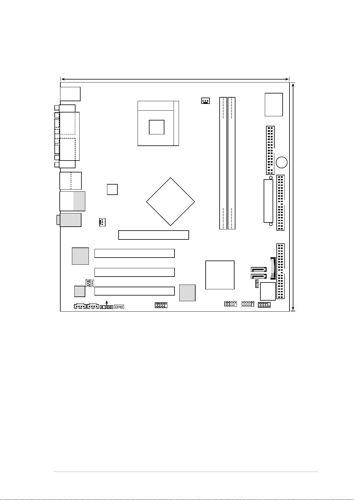
1. Motherboard layout
24.5cm (9.64in)
PS/2
T: Mouse
B: Keyboard
COM1
Socket 478
CPU_FAN1
I/O
Super
VGA
Bottom:
Top:
USB1
1394
USB2
Bottom:
Top:
USB1
RJ-45
USB2
Top:Line In
Center:Line Out
Below:Mic In
Realtek
RTL8101L
FRONT MICIN
Audio
Codec
CD_IN
PARALLEL PORT
CHA_FAN1
SPDI/F
SPEAKER OUT
AUX
ATX12V1
Accelerated Graphics Port (AGP8X1)
PCI 1
PCI 2
PCI 3
FRONT HP-OUT
Intel
Breeds Hill
MCH
Chipset
1394
TI43AB22A
1394
PHY
FLOPPY1
DDR DIMM1 (64/72 bit, 184-pin module)
DDR DIMM2 (64/72 bit, 184-pin module)
P4SD-LA
01
23
Intel
ICH5
Chipset
P31
P30
J19
ATX Power Connector
BATTERY1
4Mb
BIOS
USB2
USB1
HPANEL
BUZZER
24.5cm (9.64in)
SECONDARY IDE
PRIMARY IDE
ASUS P4SD-LA motherboard
1
2. Central Processing Unit (CPU)
The motherboard comes with a surface mount 478-pin Zero Insertion Force (ZIF)
®
socket. The socket is designed for the Intel
Pentium
processor in the 478-pin package with 512KB L2 cache. This processor supports
800/533/400MHz front side bus (FSB), and allows data transfer rates of 3.2GB/s,
2.1GB/s, and 1.6GB/s.
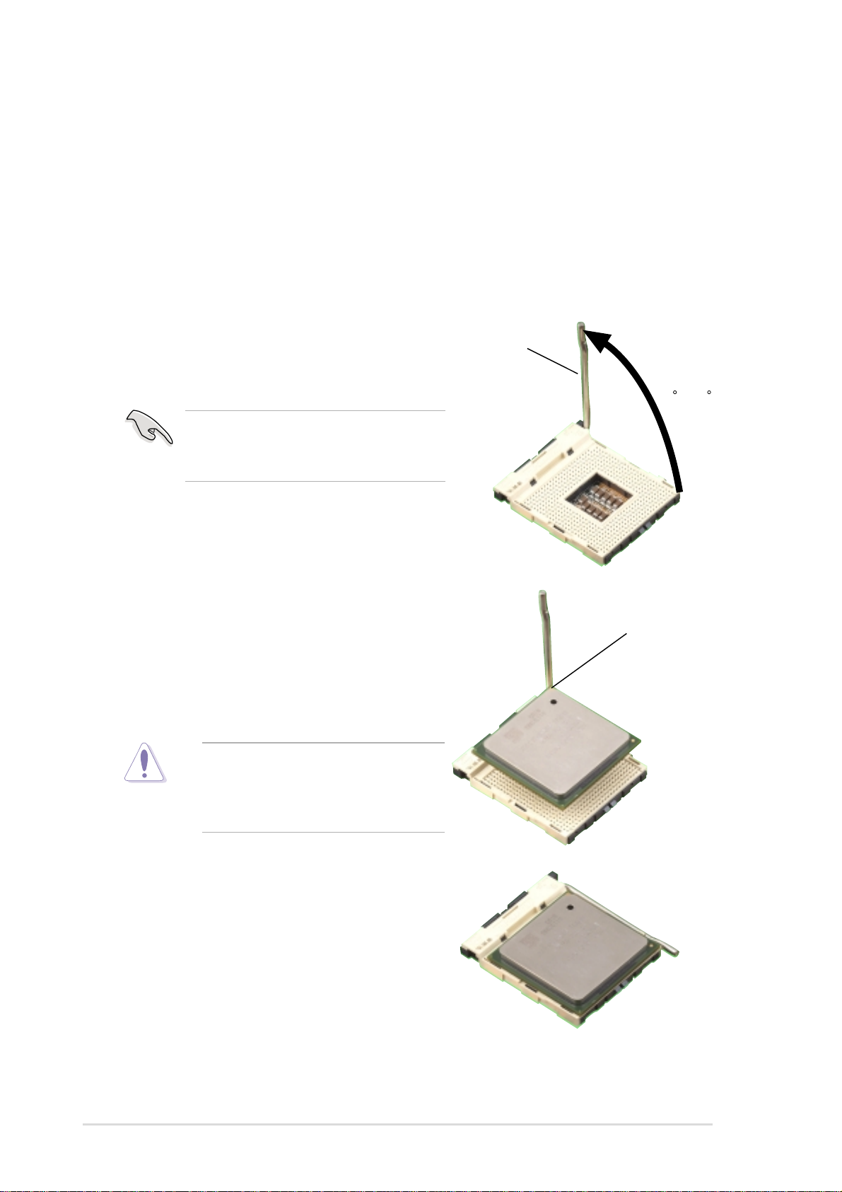
Follow these steps to install a CPU.
1. Locate the 478-pin ZIF socket on the motherboard.
®
4 Northwood/Prescott
2. Unlock the socket by pressing the
lever sideways, then lift it up to a 90°-
100° angle.
Make sure that the socket lever is lifted
up to 90°-100° angle, otherwise the
CPU does not fit in completely.
3. Position the CPU above the socket
such that its marked corner matches
the base of the socket lever.
4. Carefully insert the CPU into the
socket until it fits in place.
Socket Lever
90 -100
Gold Mark
The CPU fits only in one correct
orientation. DO NOT force the CPU
into the socket to prevent bending
the pins and damaging the CPU!
5. When the CPU is in place, push
down the socket lever to secure the
CPU. The lever clicks on the side tab
to indicate that it is locked.
6. Install a CPU heatsink and fan
following the instructions that came
with the heatsink package.
7. Connect the CPU fan cable to the
CPU_FAN1 connector on the
motherboard.
2
ASUS P4SD-LA motherboard
 Loading...