

Asus AW171 User Manual

SK8N
User Guide
Motherboard

Checklist
E131 1
First Edition
June 2003
Copyright © 2003 ASUSTeK COMPUTER INC. All Rights Reserved.
No part of this manual, including the products and software described in it, may be
reproduced, transmitted, transcribed, stored in a retrieval system, or translated into any
language in any form or by any means, except documentation kept by the purchaser for
backup purposes, without the express written permission of ASUSTeK COMPUTER INC.
(“ASUS”).
Product warranty or service will not be extended if: (1) the product is repaired, modified or
altered, unless such repair, modification of alteration is authorized in writing by ASUS; or (2)
the serial number of the product is defaced or missing.
ASUS PROVIDES THIS MANUAL “AS IS” WITHOUT WARRANTY OF ANY KIND, EITHER
EXPRESS OR IMPLIED, INCLUDING BUT NOT LIMITED TO THE IMPLIED WARRANTIES
OR CONDITIONS OF MERCHANTABILITY OR FITNESS FOR A PARTICULAR PURPOSE.
IN NO EVENT SHALL ASUS, ITS DIRECTORS, OFFICERS, EMPLOYEES OR AGENTS BE
LIABLE FOR ANY INDIRECT, SPECIAL, INCIDENTAL, OR CONSEQUENTIAL DAMAGES
(INCLUDING DAMAGES FOR LOSS OF PROFITS, LOSS OF BUSINESS, LOSS OF USE
OR DATA, INTERRUPTION OF BUSINESS AND THE LIKE), EVEN IF ASUS HAS BEEN
ADVISED OF THE POSSIBILITY OF SUCH DAMAGES ARISING FROM ANY DEFECT OR
ERROR IN THIS MANUAL OR PRODUCT.
SPECIFICATIONS AND INFORMATION CONTAINED IN THIS MANUAL ARE FURNISHED
FOR INFORMATIONAL USE ONLY, AND ARE SUBJECT TO CHANGE AT ANY TIME
WITHOUT NOTICE, AND SHOULD NOT BE CONSTRUED AS A COMMITMENT BY ASUS.
ASUS ASSUMES NO RESPONSIBILITY OR LIABILITY FOR ANY ERRORS OR
INACCURACIES THAT MAY APPEAR IN THIS MANUAL, INCLUDING THE PRODUCTS
AND SOFTWARE DESCRIBED IN IT.
Products and corporate names appearing in this manual may or may not be registered
trademarks or copyrights of their respective companies, and are used only for identification or
explanation and to the owners’ benefit, without intent to infringe.
ii

Contents
Notices ...........................................................................................vi
Safety information ......................................................................... vii
About this guide............................................................................ viii
How this guide is organized ................................................ viii
Conventions used in this guide ............................................. ix
Where to find more information ............................................. ix
ASUS contact information ...............................................................x
SK8N specifications summary........................................................xi
Chapter 1: Product introduction
1.1 Welcome! ........................................................................... 1-1
1.2 Package contents............................................................... 1-1
1.3 Special features.................................................................. 1-2
1.3.1 Product highlights .................................................. 1-2
1.3.2 Value-added solutions............................................ 1-5
1.4 Motherboard overview........................................................ 1-6
1.4.1 Major components ................................................. 1-6
1.4.2 Core specifications ................................................ 1-8
Features
Chapter 2: Hardware information
2.1 Motherboard installation ..................................................... 2-1
2.1.1 Placement direction ............................................... 2-1
2.1.2 Screw holes ........................................................... 2-1
2.2 Motherboard layout ............................................................ 2-2
2.3 Before you proceed ............................................................ 2-3
2.4 Central Processing Unit (CPU)........................................... 2-4
2.4.1 Overview ................................................................ 2-4
2.4.2 Installing the CPU .................................................. 2-5
2.4.3 Installing the heatsink and fan ............................... 2-7
2.4.4 Connecting the CPU Fan cable ............................. 2-9
2.4.5 CPU heatsink and fan qualified vendor list .......... 2-10
2.5 System memory ................................................................2-11
2.5.1 Overview ...............................................................2-11
2.5.2 Memory configurations ........................................ 2-12
2.5.3 Installing a DIMM ................................................. 2-14
2.5.4 Removing a DIMM ............................................... 2-14
iii

Safeguards
Contents
2.6 Expansion slots ................................................................ 2-15
2.6.1 Installing an expansion card ................................ 2-15
2.6.2 Configuring an expansion card ............................ 2-15
2.6.3 PCI slots .............................................................. 2-17
2.6.4 AGP slot............................................................... 2-18
2.7 Jumpers............................................................................ 2-19
2.8 Connectors ....................................................................... 2-21
Chapter 3: Powering up
3.1 Starting up for the first time ................................................ 3-1
3.2 Powering off the computer ................................................. 3-2
Chapter 4: BIOS setup
4.1 Managing and updating your BIOS .................................... 4-1
4.1.1 Creating a bootable floppy disk ............................. 4-1
4.1.2 Using AFUDOS to update the BIOS ...................... 4-1
4.1.3 Using AFUDOS to copy BIOS from PC ................. 4-3
4.1.4 Using ASUS EZ Flash to update the BIOS ............ 4-4
4.1.5 Recovering the BIOS with CrashFree BIOS 2 ....... 4-5
4.2 BIOS Setup program .......................................................... 4-7
4.2.1 BIOS menu screen ................................................ 4-8
4.2.2 Menu bar................................................................ 4-8
4.2.3 Navigation keys ..................................................... 4-8
4.2.4 Menu items ............................................................ 4-9
4.2.5 Sub-menu items..................................................... 4-9
4.2.6 Configuration fields ................................................ 4-9
4.2.7 Pop-up window ...................................................... 4-9
4.2.8 Scroll bar................................................................ 4-9
4.2.9 General help .......................................................... 4-9
4.3 Main menu........................................................................ 4-10
4.3.1 System Time [xx:xx:xxxx]..................................... 4-10
4.3.2 System Date [Day xx/xx/xxxx] ............................. 4-10
4.3.3 Legacy Diskette A [1.44M, 3.5 in.] ....................... 4-10
4.3.4 Primary and Secondary IDE Master/Slave ...........4-11
4.3.5 System Information .............................................. 4-12
4.4 Advanced menu ............................................................... 4-13
4.4.1 CPU Configuration ............................................... 4-13
4.4.2 Chipset................................................................. 4-14
4.4.3 Onboard Devices Configuration........................... 4-22
4.4.4 PCI PnP ............................................................... 4-23
iv

Contents
4.5 Power menu ..................................................................... 4-25
4.5.1 ACPI Suspend Mode [Auto] ................................. 4-25
4.5.2 Repost Video on S3 Resume [No] ....................... 4-25
4.5.3 ACPI 2.0 Support [No] ......................................... 4-25
4.5.4 ACPI APIC Support [Enabled] ............................. 4-25
4.5.5 BIOS -> AML ACPI Table [Enabled] ..................... 4-25
4.5.6 APM Configuration............................................... 4-26
4.5.7 Hardware Monitor ................................................ 4-27
4.6 Boot menu ........................................................................ 4-29
4.6.1 Boot Device Priority ............................................. 4-29
4.6.2 Boot Settings Configuration ................................. 4-30
4.6.3 Security ................................................................ 4-32
4.7 Exit menu ......................................................................... 4-34
Chapter 5: Software support
5.1 Install an operating system................................................. 5-1
5.2 Support CD information...................................................... 5-1
5.2.1 Running the support CD ........................................ 5-1
5.2.2 Drivers menu ......................................................... 5-2
5.2.3 Utilities menu ......................................................... 5-3
5.2.4 ASUS Contact Information..................................... 5-4
5.2.5 Other information ................................................... 5-5
5.3 Software information .......................................................... 5-7
5.3.1 ASUS Update ........................................................ 5-7
5.3.2 ASUS MyLogo2™.................................................. 5-8
5.3.3 ASUS PC Probe .................................................. 5-10
5.3.4 Multi-channel Audio Feature ................................ 5-15
5.4 RAID configurations ......................................................... 5-17
5.4.1 Install the hard disks ............................................ 5-18
5.4.2 Enter the MBFastBuild™ utility ............................ 5-19
5.4.3 Creating a RAID 0 array (Performance) .............. 5-20
5.4.4 Creating a RAID 1 array (Security) ...................... 5-21
5.4.5 Other FastBuild Utility Commands....................... 5-23
5.5 Using Makedisk.exe ......................................................... 5-25
v

Notices
Federal Communications Commission Statement
This device complies with FCC Rules Part 15. Operation is subject to the
following two conditions:
• This device may not cause harmful interference, and
• This device must accept any interference received including interference
that may cause undesired operation.
This equipment has been tested and found to comply with the limits for a
Class B digital device, pursuant to Part 15 of the FCC Rules. These limits
are designed to provide reasonable protection against harmful interference
in a residential installation. This equipment generates, uses and can radiate
radio frequency energy and, if not installed and used in accordance with
manufacturer’s instructions, may cause harmful interference to radio
communications. However, there is no guarantee that interference will not
occur in a particular installation. If this equipment does cause harmful
interference to radio or television reception, which can be determined by
turning the equipment off and on, the user is encouraged to try to correct the
interference by one or more of the following measures:
• Reorient or relocate the receiving antenna.
• Increase the separation between the equipment and receiver.
• Connect the equipment to an outlet on a circuit different from that to
which the receiver is connected.
• Consult the dealer or an experienced radio/TV technician for help.
The use of shielded cables for connection of the monitor to the
graphics card is required to assure compliance with FCC regulations.
Changes or modifications to this unit not expressly approved by the
party responsible for compliance could void the user’s authority to
operate this equipment.
Canadian Department of Communications Statement
This digital apparatus does not exceed the Class B limits for radio noise
emissions from digital apparatus set out in the Radio Interference
Regulations of the Canadian Department of Communications.
This class B digital apparatus complies with Canadian ICES-003.
vi

Safety information
Electrical safety
• To prevent electrical shock hazard, disconnect the power cable from
the electrical outlet before relocating the system.
• When adding or removing devices to or from the system, ensure that
the power cables for the devices are unplugged before the signal
cables are connected. If possible, disconnect all power cables from the
existing system before you add a device.
• Before connecting or removing signal cables from the motherboard,
ensure that all power cables are unplugged.
• Seek professional assistance before using an adpater or extension
cord. These devices could interrupt the grounding circuit.
• Make sure that your power supply is set to the correct voltage in your
area. If you are not sure about the voltage of the electrical outlet you
are using, contact your local power company.
• If the power supply is broken, do not try to fix it by yourself. Contact a
qualified service technician or your retailer.
Operation safety
• Before installing the motherboard and adding devices on it, carefully
read all the manuals that came with the package.
• Before using the product, make sure all cables are correctly connected
and the power cables are not damaged. If you detect any damage,
contact your dealer immediately.
• To avoid short circuits, keep paper clips, screws, and staples away from
connectors, slots, sockets and circuitry.
• Avoid dust, humidity, and temperature extremes. Do not place the
product in any area where it may become wet.
• Place the product on a stable surface.
• If you encounter technical problems with the product, contact a
qualified service technician or your retailer.
vii

About this guide
This user guide contains the information you need when installing the
ASUS SK8N motherboard.
How this guide is organized
This manual contains the following parts:
• Chapter 1: Product introduction
This chapter describes the features of the SK8N motherboard. It
includes brief descriptions of the special attributes of the motherboard
and the new technology it supports.
• Chapter 2: Hardware information
This chapter lists the hardware setup procedures that you have to
perform when installing system components. It includes description of
the switches, jumpers, and connectors on the motherboard.
• Chapter 3: Powering up
This chapter describes the power up sequence and ways of shutting
down the system.
• Chapter 4: BIOS setup
This chapter tells how to change system settings through the BIOS
Setup menus. Detailed descriptions of the BIOS parameters are also
provided.
• Chapter 5: Software support
This chapter describes the contents of the support CD that comes with
the motherboard package.
viii
Conventions used in this guide
To make sure that you perform certain tasks properly, take note of the
following symbols used throughout this manual.
DANGER/WARNING: Information to prevent injury to yourself
when trying to complete a task.
CAUTION: Information to prevent damage to the components
when trying to complete a task.
IMPORTANT: Information that you MUST follow to complete a
task.
NOTE: Tips and additional information to aid in completing a task.
Where to find more information
Refer to the following sources for additional information and for product
and software updates.
1. ASUS Websites
The ASUS websites worldwide provide updated information on ASUS
hardware and software products. The ASUS websites are listed in the
ASUS Contact Information on page x.
2. Optional Documentation
Your product package may include optional documentation, such as
warranty flyers, that may have been added by your dealer. These
documents are not part of the standard package.
ix

ASUS contact information
ASUSTeK COMPUTER INC. (Asia-Pacific)
Address: 150 Li-Te Road, Peitou, Taipei, Taiwan 112
General Tel: +886-2-2894-3447
General Fax: +886-2-2894-3449
General Email: info@asus.com.tw
Technical Support
MB/Others (Tel): +886-2-2890-7121 (English)
Notebook (Tel): +886-2-2890-7122 (English)
Desktop/Server (Tel): +886-2-2890-7123 (English)
Support Fax: +886-2-2890-7698
Web Site: www.asus.com.tw
ASUS COMPUTER INTERNATIONAL (America)
Address: 44370 Nobel Drive, Fremont, CA 94538, USA
General Fax: +1-502-933-8713
General Email: tmd1@asus.com
Technical Support
Support Fax: +1-502-933-8713
General Support: +1-502-995-0883
Notebook Support: +1-510-739-3777 x5110
Web Site: usa.asus.com
Support Email: tsd@asus.com
ASUS COMPUTER GmbH (Germany and Austria)
Address: Harkortstr. 25, 40880 Ratingen, BRD, Germany
General Email: sales@asuscom.de (for marketing requests only)
General Fax: +49-2102-9599-31
Technical Support
Support Hotlines: (Components) +49-2102-9599-0
(Notebook PC) +49-2102-9599-10
Support Fax: +49-2102-9599-11
Support Email: www.asuscom.de/kontakt (for online support)
Web Site: www.asuscom.de
x
SK8N specifications summary
CPU
Chipset
System Bus
Memory
Expansion slots
Storage
Audio
Socket 940 for AMD Opteron processor
NVIDIA nForce 3 Pro150
Scalable Hyper-Transport Bus
Dual-Channel memory architecture
Supports PC2700/PC2100/PC1600 ECC DDR SDRAM
Registered DIMMs
4 x 184-pin DDR DIMM sockets for up to 8GB memory
1 x AGP 8X
5 x PCI
2 x UltraDMA 133/100
Promise PDC20378 RAID controller:
1 x UltraDMA 133 support for two hard drives
2 x Serial ATA
RAID 0, RAID 1, RAID 0+1
ALC 650
S/PDIF out interface
LAN
USB 2.0
IEEE 1394
Special Features
Internal I/O
connectors
OverclockFeatures
CK8 MAC+ Realtek RTL8201BL PHY
Integrated 6 USB 2.0 ports
2 x port at 400 Mbps transfer rate
ASUS MyLogo2
ASUS EZ Flash
Supports S/PDIF out interface
ASUS CrashFree BIOS 2
ASUS Q-Fan
1 x USB 2.0 connector support additional 2 USB 2.0 ports
20-pin ATX power connector
4-pin ATX 12V power connector
CPU/chassis/power FAN connectors
COM2 connector
CD/AUX audio-in
IEEE 1394 connector
ASUS Jumperfree
Memory and AGP voltage adjustable
SFS (Stepless Frequency Selection) from 200MHz up to
300MHz at 1MHz increment
(continued on the next page)
xi

SK8N specifications summary
Back Panel I/O Ports
BIOS features
Industry standard
Manageability
Form Factor
Support CD contents
1 x Parallel
1 x Serial
1 x PS/2 Keyboard
1 x PS/2 Mouse
1 x Audio I/O
4 x USB 2.0
1 x RJ-45 Port
1 x IEEE 1394
4Mb Flash EEPROM
AMI BIOS with enhanced ACPI, DMI, PnP, Green
ASUS EZ Flash, ASUS MyLogo2, ASUS Q-Fan,
CrashFree BIOS 2, SM BIOS 2.3
PCI 2.3, USB 2.0
WOL by PME, WOR by PME
ATX form factor: 12 in x 9.6 in (30.5 cm x 24.5 cm)
Device drivers
ASUS PC Probe
Trend Microtm PC-cillin 2002 anti-virus software
* Specifications are subject to change without notice.
xii

Chapter 1
This chapter describes the features of the
SK8N motherboard. It includes brief
explanations of the special attributes of the
motherboard and the new technology it
supports.
Product introduction

Chapter summary
1.1 Welcome! ........................................................ 1-1
1.2 Package contents .......................................... 1-1
1.3 Special features ............................................. 1-2
1.4 Motherboard overview................................... 1-6
ASUS SK8N motherboard

1.1 Welcome!
Thank you for buying the ASUS
The ASUS
SK8N motherboard delivers a host of new features and latest
®
SK8N motherboard!
technologies making it another standout in the long line of ASUS quality
motherboards!
The SK8N incorporates the AMD
®
Opteron™ Processor in a Socket 940
package that is designed for high performance workstation and server
applications. It provides three high-performance HyperTransport™ links to
I/O devices, as well as a 128-bit high-performance DDR SDRAM memory
controller with the NVIDIA
®
nForce 3 Pro150 chipset that sets a new
benchmark for an effective desktop platform solution.
Supporting up to 8GB of system memory with PC2700/PC2100/PC1600
DDR SDRAM registered modules, high-resolution graphics via an AGP 8X
slot, Serial ATA support, RAID, IEEE 1394, USB 2.0, and 6-channel audio
features, the SK8N takes you ahead in the world of power computing!
Before you start installing the motherboard, and hardware devices on it,
check the items in your package with the list below.
1.2 Package contents
Check your SK8N package for the following items.
ASUS SK8N motherboard
ASUS support CD
2 x SATA cable
1 x USB cable
1 x COM2 cable
1 x Single port 1394 module
S/PDIF out module
80-conductor ribbon cable for UltraDMA/66/100/133 IDE drives
40-conductor IDE cable
Ribbon cable for a 3.5-inch floppy drive
I/O shield
Bag of extra jumper caps
User Guide
If any of the above items is damaged or missing, contact your retailer.
ASUS SK8N motherboard user guide
1-1

1.3 Special features
1.3.1 Product highlights
Latest processor technology
The AMD Opteron™ processor for servers and workstations is based on
AMD’s 64-bit architecture, which represents the landmark introduction of
the industry’s first x86-64 technology. This next-generation processor
provides a dramatic leap forward in compatibility, performance, investment
protection, and reduced total cost of ownership and development. See
page 2-4 for details.
HyperTransport™ Technology
HyperTransport™ Technology is a high-speed, low latency, point-to-point link
designed to increase the communication speed between integrated circuits
in computers, servers, embedded systems, and networking and
telecommunicatons equipment up to 48 times faster than some existing
technologies.
Serial ATA solution, RAID support
The motherboard supports two interfaces compliant to the Serial ATA
(SATA) specification, an evolutionary replacement of the Parallel ATA
storage interface. The Serial ATA specification allows for thinner, more
flexible cables with lower pin count, reduced voltage requirement, up to
150 MB/s data transfer rate. With the Promise
controller onboard, the motherboard supports RAID 0, RAID 1 and RAID
0+1 configuration using SATA drives. See pages 2-23, 5-17.
®
PDC 20378 RAID
AGP 8X support
AGP 8X (AGP 3.0) is the next generation VGA interface specification that
enables enhanced graphics performance with high bandwidth speeds up
to 2.12 GB/s. See page 2-18.
6-Channel Audio solution
The SK8N uses an onboard audio CODEC that lets you enjoy high-quality
6-channel audio without having to buy advanced sound cards. See page
5-15.
S/PDIF out
The SK8N’s S/PDIF out function turns your computer into a high-end
entertainment system with digital connectivity to powerful speaker
systems.
1-2
Chapter 1: Product introduction

IEEE 1394 support
The IEEE 1394 interface provides high-speed and flexible PC connectivity
to a wide range of peripherals and devices compliant to IEEE 1394a
standards. The IEEE 1394 interface allows up to 400Mbps transfer rates
through simple, low-cost, high-bandwidth asynchronous (real-time) data
interfacing between computers, peripherals, and consumer electronic
devices such as camcorders, VCRs, printers,TVs, and digital cameras.
See page 2-28.
USB 2.0 technology
The motherboard implements the new Universal Serial Bus (USB) 2.0
specification, extending the connection speed from 12 Mbps on USB 1.1
to a fast 480 Mbps on USB 2.0 - supporting up to 6 USB 2.0 ports. The
higher bandwidth of USB 2.0 allows connection of devices such as high
resolution video conferencing cameras, next generation scanners and
printers, and fast storage units. USB 2.0 is backward compatible with USB
1.1. See page 2-20.
ASUS MyLogo2™
This new feature present in the SK8N motherboard allows you to
personalize and add style to your system with customizable boot logos.
See pages 4-30, 5-8.
ASUS EZ Flash BIOS
With the ASUS EZ Flash, you can easily update the system BIOS even
before loading the operating system. No need to use a DOS-based utility
or boot from a floppy disk. See page 4-4.
ASUS Q-Fan technology
The ASUS Q-Fan technology smartly adjusts the fan speeds according to
the system loading to ensure quiet, cool, and efficient operation. See page
4-28.
ASUS SK8N motherboard user guide
1-3

CrashFree BIOS 2
This feature allows you to restore the original BIOS data from the ASUS
support CD in case when the BIOS codes and data are corrupted. This
protection eliminates the need to buy a replacement ROM chip. See page
4-5.
BONUS!
Free bundled TrendMIcro™ PC-cillin 2002 anti-virus software (OEM
version)
1-4
Chapter 1: Product introduction

1.3.2 Value-added solutions
Temperature, fan, and voltage monitoring
The CPU temperature is monitored by the IT8712F to prevent overheating
and damage. The system fan rotations per minute (RPM) is monitored for
timely failure detection. The system voltage levels are monitored to ensure
stable supply of current for critical components.
ASUS update
This utility allows you to update the motherboard BIOS through a userfriendly interface. Connect to the Internet then to the ASUS FTP site
nearest you to obtain the latest BIOS version for your motherboard.
ASUS SK8N motherboard user guide
1-5

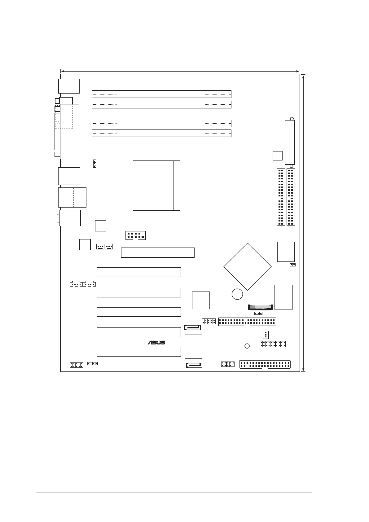
1.4 Motherboard overview
Before you install the SK8N motherboard, familiarize yourself with its
physical configuration and available features to facilitate the motherboard
installation and future upgrades. A sufficient knowledge of the motherboard
specifications will also help you avoid mistakes that may damage the
board and its components.
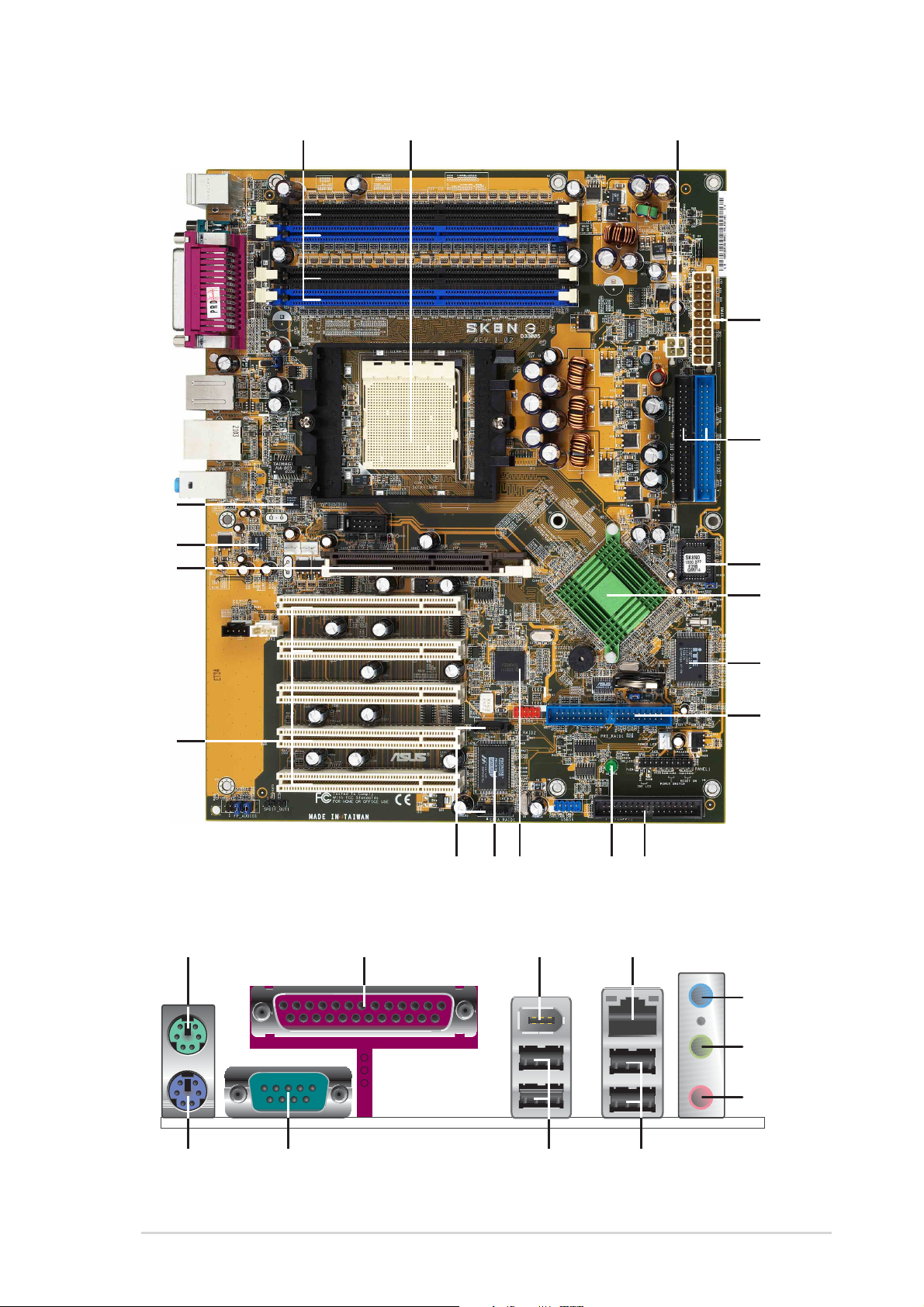
1.4.1 Major components
The following are the major components of the SK8N motherboard as
pointed out in the picture on page 1-7.
1. DDR DIMM sockets
2. CPU socket
3. 12V ATX power connector
4. ATX Power connector
5. IDE connectors
6. Flash ROM
7. System chipset
8. Super I/O controller
9. Floppy disk connector
10. RAID Ultra ATA/133 connector
11. Standby power LED
12. IEEE 1394 controller
13. Serial A TA controller
14. Serial A TA connectors
15. PCI slots
16. AGP slot
17. Audio CODEC
18. LAN PHY
19. PS/2 Mouse
20. Parallel port
21. IEEE 1394 port
22. RJ-45 port
23. Line In jack
24. Line Out jack
25. Microphone jack
26. USB 2.0 ports 1 and 2
27. USB 2.0 ports 3 and 4
28. Serial port
29. Keyboard port
1-6
See page 1-8 for the specifications of each component. Refer to
Chapter 2 for detailed information on the components.
Chapter 1: Product introduction
1 2
3
5
4
7
6
8
18
9
19
3
4
5
20 22
21
17
16
15
29
28
13
27
11
1014 12
2
2
2
26
ASUS SK8N motherboard user guide
1-7

1.4.2 Core specifications
1
DDR DIMM sockets. These four 184-pin DIMM sockets support up to
8GB system memory using registered ECC PC2700/2100/1600 DDR
DIMMs.
2
CPU socket. A 940-pin surface mount, Zero Insertion Force (ZIF)
socket designed for the AMD
®
Opteron™processor with an
integrated low-latency high-bandwidth memory controller and a
highly-scalable HyperTransport™ technology-based system bus.
3
ATX 12V connector. This power connector connects the 4-pin 12V
plug from the ATX 12V power supply .
4
ATX power connector . This 20-pin connector connects to an ATX
+12V power supply. The power supply must have at least 1.5A on the
+5V standby lead (+5VSB).
5
IDE connectors. These dual-channel bus master IDE connectors
support Ultra DMA133/100, PIO Modes 3 & 4 IDE devices. Both the
primary (blue) and secondary (black) connectors are slotted to prevent
incorrect insertion of the IDE ribbon cable.
6
7
8
9
10
Flash ROM. This 4Mb firmware contains the programmable BIOS
program.
System chipset. Th e Nvidia
®
nForce 3 Pro 150 is a low-latency
subsystem that provides an extremely fast dedicated
HyperTransport link that sets the communication with the CPU at
up to 3.6 GB/s, a speed that ensures ample bandwidth for
integrated support for AGP, PCI, Serial ATA and other devices.
Super I/O controller . The ITE IT8712F-A interface provides the
commonly used Super I/O functionality. The chipset supports a highperformance floppy disk controller for a 360K/720K/1.44M/2.88M
floppy disk drive, a multi-mode parallel port, 2 serial ports, the mouse
and keyboard interface and the LPC (Low Pin Count) interface.
Floppy disk connector . This connector accommodates the provided
ribbon cable for the floppy disk drive. One side of the connector is
slotted to prevent incorrect insertion of the floppy disk cable.
RAID A TA133 connector . This bus master IDE connector supports
Ultra DMA/133 IDE devices. This connector is slotted to prevent
incorrect insertion of the IDE ribbon cable.
1-8
Chapter 1: Product introduction

11
Standby power LED. This LED lights up if there is a standby
power on the motherboard. This LED acts as a reminder to turn off
the system power before plugging or unplugging devices.
12
13
14
15
IEEE 1394 controller. The Texas Instruments TSB43AB22A device
is an integrated 1394a-2000 OHCI PHY/link-layer controller (LLC)
device that is fully compliant with the PCI Local Bus Specification,
the PCI Bus Power Management Interface Specification, IEEE Std
1394-1995, IEEE Std 1394a-2000, and the 1394 Open Host
Controller Interface Specification. It is capable of transferring data
between the 33-MHz PCI bus and the 1394 bus at 100M bits/s,
200M bits/s, and 400M bits/s.
SATA RAID controller. The Promise
®
PDC20378 RAID controller
provides high-performance RAID 0/RAID 1/RAID 0+1. Together
with the UltraDMA133 devices, if present, the Serial ATA RAID
devices may be set up as a multi-RAID configuration.
SATA connectors. These two 7-pin connectors support Serial ATA
HDDs and allows for up to 150MB/s data transfer rate, faster than
the standard Parallel ATA with 133 MB/s.
PCI slots. These five 32-bit PCI 2.3 expansion slots support bus
master PCI cards like SCSI or LAN cards with 133MB/s maximum
throughput.
16
17
18
19
20
21
AGP slot. This Accelerated Graphics Port (AGP) slot supports 1.5V
AGP8X mode graphics cards for 3D graphical applications.
Audio CODEC. The Realtek
®
ALC 650 is an AC’97 CODEC that
allows 6-channel audio playback. The audio CODEC provides six
DAC channels for 5.1 surround sound, AUX and Line In stereo
inputs, and an integrated headphone amplifier.
LAN PHY. The Realtek
®
RTL8201BL Ethernet PHY with the CK8
MAC forms a solution for LAN on Motherboard (LOM) application.
They support 100/10 Mbps data transfer rates.
PS/2 mouse port. This green 6-pin connector is for a PS/2 mouse.
Parallel port. This 25-pin port connects a parallel printer, a scanner ,
or other devices.
IEEE1394 port. This 6-pin IEEE 1394 port provides high-speed
connectivity for audio/video devices, storage peripherals, other
PCs and/or portable devices.
ASUS SK8N motherboard user guide
1-9

22
RJ-45 port. This port allows connection to a Local Area Network
(LAN) through a network hub.
23
24
25
26
27
28
Line In jack. This Line In (light blue) jack connects a tape player or
other audio sources. In 6-channel mode, the function of this jack
becomes Rear Speaker Out.
Line Out jack. This Line Out (lime) jack connects a headphone or a
speaker . In 6-channel mode, the function of this jack becomes Front
Speaker Out.
Microphone jack. This Mic (pink) jack connects a microphone. In 6channel mode, the function of this jack becomes Bass/Center
Speaker Out.
USB 2.0 ports 1 and 2. These two 4-pin Universal Serial Bus
(USB) ports are available for connecting USB 2.0 devices.
USB 2.0 ports 3 and 4. These two 4-pin Universal Serial Bus (USB)
ports are available for connecting USB 2.0 devices.
Serial port. This 9-pin COM1 port is for pointing devices or other
serial devices.
29
PS/2 keyboard port. This purple connector is for a PS/2 keyboard.
1-10
Chapter 1: Product introduction

Chapter 2
This chapter describes the hardware setup
procedures that you have to perform when
installing system components. It includes
details on the switches, jumpers, and
connectors on the motherboard.
Hardware information

Chapter summary
2.1 Motherboard installation ............................... 2-1
2.2 Motherboard layout ....................................... 2-2
2.3 Before you proceed ....................................... 2-3
2.4 Central Processing Unit (CPU) ..................... 2-4
2.5 System memory ............................................2-11
2.6 Expansion slots ........................................... 2-15
2.7 Jumpers ........................................................ 2-19
2.8 Connectors ................................................... 2-21
ASUS SK8N motherboard
2.1 Motherboard installation
Before you install the motherboard, study the configuration of your chassis
to ensure that the motherboard fits into it. The SK8N uses the ATX form
factor that measures 12 inches x 9.6 inches.
Make sure to unplug the power cord before installing or removing the
motherboard. Failure to do so may cause you physical injury and
damage motherboard components.
2.1.1 Placement direction
When installing the motherboard, make sure that you place it into the
chassis in the correct orientation. The edge with external ports goes to the
rear part of the chassis as indicated in the image below.
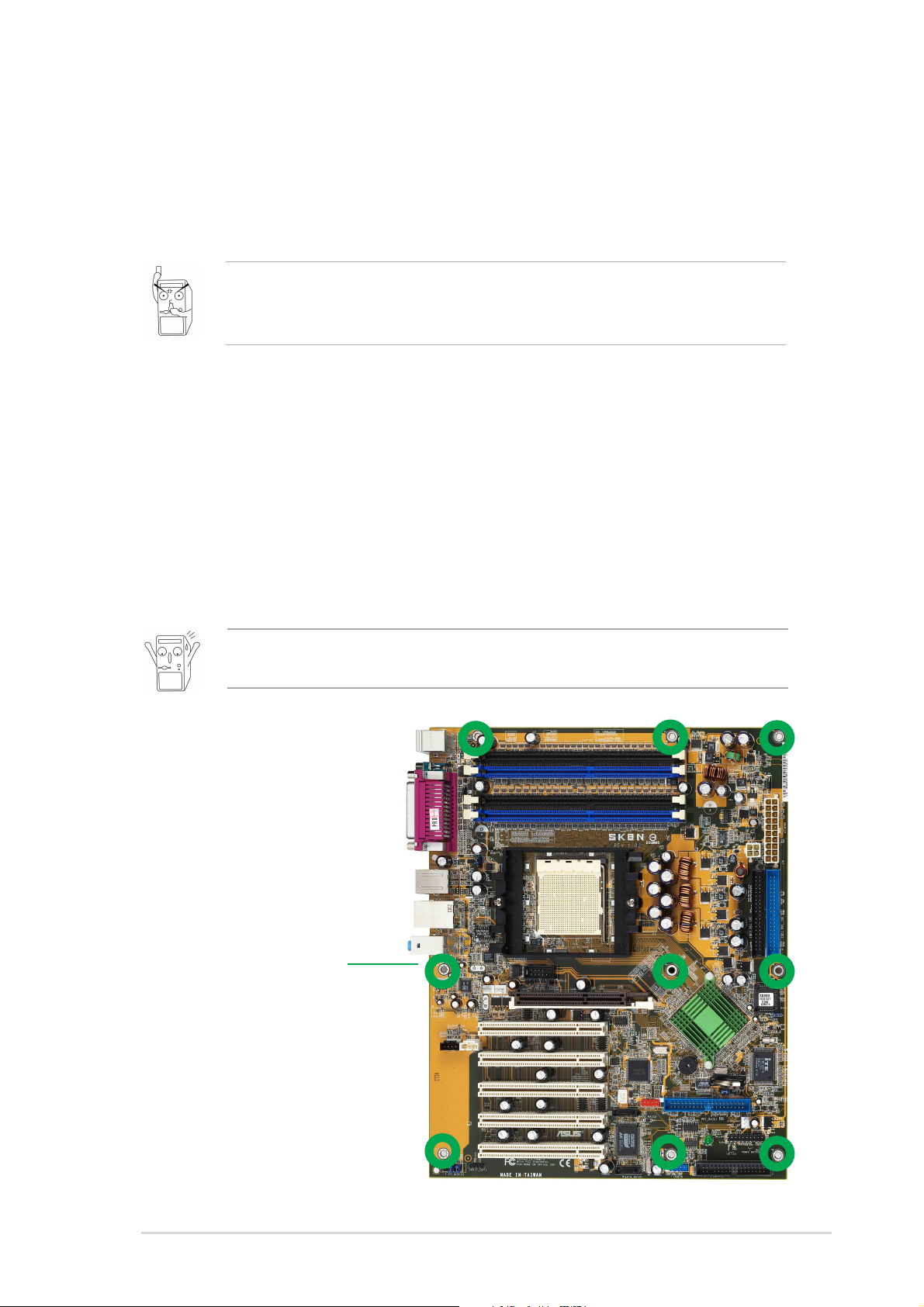
2.1.2 Screw holes
Place nine (9) screws into the holes indicated by circles to secure the
motherboard to the chassis.
Do not overtighten the screws! Doing so may damage the
motherboard.
Place this side towards
the rear of the chassis
ASUS SK8N motherboard user guide
2-1
2.2 Motherboard layout
®
24.5cm (9.6in)
PS/2KBMS
T: Mouse
B: Keyboard
COM1
DDR DIMM_B2 (64 bit,184-pin module)
DDR DIMM_B1 (64 bit,184-pin module)
DDR DIMM_A2 (64 bit,184-pin module)
DDR DIMM_A1 (64 bit,184-pin module)
Bottom:
Top:
T:USB4
1394
B:USB3
USB2.0
T: USB1
B: USB2
Top:Line In
Center:Line Out
Below:Mic In
CD1 AUX1
PARALLEL PORT
Top:
RJ-45
CODEC
AUDIO
PWR_FAN1
USBPW1234
RTL
8201BL
CPU_FAN1
SK8N
Socket 940
COM2
Accelerated Graphics Port (AGP1)
PCI1
PCI2
PCI3
SATA_RAID2
PCI4
1394PHY
TI
TSB43AB22A
IE1394_1
BUZZER1
PRI_RAID1
nVIDIA
nForce3
Pro150
CHA_FAN1
ATX12V
CLRTC1
SEC_IDE
PANEL1
ATX Power Connector
PRI_IDE
30.5cm (12.0in)
ROM
4Mbit
LPC BIOS
J1
I/O
Super
PCI5
FP_AUDIO1
SPDIF_OUT
SATA_RAID1
2-2
RAID
Controller
PROMISE
PDC20378
Chapter 2: Hardware information
SB_PWR1
FLOPPY1
USB56
2.3 Before you proceed
®
d
Take note of the following precautions before you install motherboard
components or change any motherboard settings.
1. Unplug the power cord from the wall socket before touching any
component.
2. Use a grounded wrist strap or touch a safely grounded object or to
a metal object, such as the power supply case, before handling
components to avoid damaging them due to static electricity.
3. Hold components by the edges to avoid touching the ICs on them.
4. Whenever you uninstall any component, place it on a grounded
antistatic pad or in the bag that came with the component.
5. Before you install or remove any component, ensure that the
ATX power supply is switched off or the power cord is
detached from the power supply. Failure to do so may cause
severe damage to the motherboard, peripherals, and/or
components.
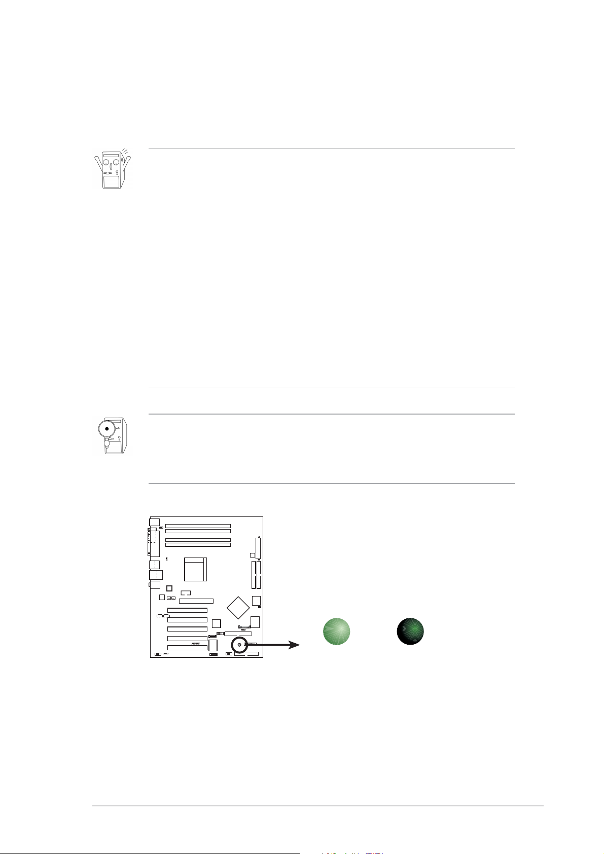
When lit, the green LED (SB_PWR1) indicates that the system is ON,
in sleep mode, or in soft-off mode, a reminder that you should shut
down the system and unplug the power cable before removing or
plugging in any motherboard component.
SK8N
SB_PWR1
SK8N Onboard LED
ON
Standby
Power
OFF
Powere
Off
ASUS SK8N motherboard user guide
2-3
2.4 Central Processing Unit (CPU)
2.4.1 Overview
The motherboard comes with a surface mount 940-pin Zero Insertion
Force (ZIF) socket. The socket is designed for the new AMD Opteron™
Processor in the 940-pin lidded ceramic micro PGA package. The AMD
Opteron™ processor is a 64-bit server and workstation processor based
on the industry-standard x86 instruction set architecture that can run x86based 32 and 64-bit applications. Integrated with the processor is a lowlatency high-bandwidth memory controller and a highly scalable
HyperTransport™ technology-based system bus. Also, the processor
includes Error Correcting Code (ECC) protection for L1 and L2 cache data
and DRAM ECC protection with chipkill.
Additionally, the 128-bit-wide data paths of the AMD Opteron™ processor
run applications faster than traditional processors with only 32 or 64-bit
wide data paths. Current 32-bit processors have a 4 gigabyte memory
addressing cap; the AMD Opteron™ has a 40-bit physical and 48-bit
virtual addressing cap that enable systems to address up to 1 terabyte of
physical memory space and 256 terabytes of virtual memory.
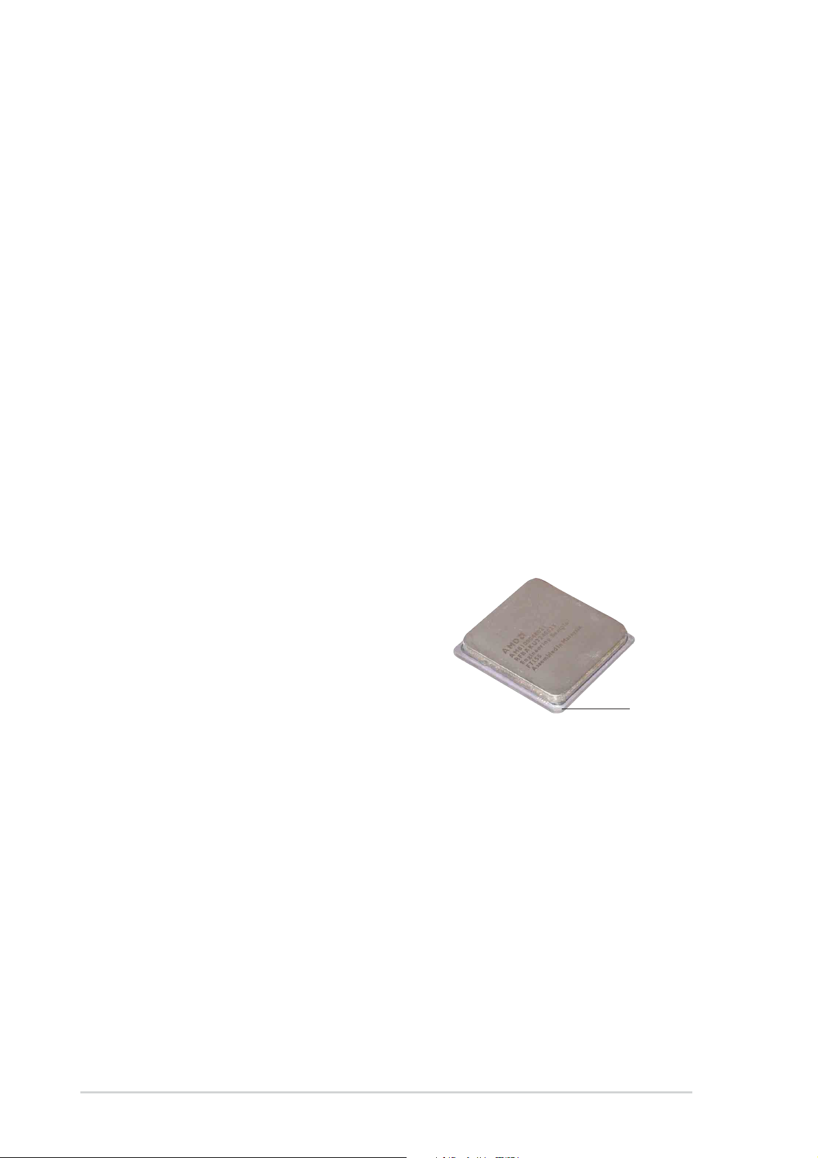
Note in the illustration that the CPU
has a chamfer in one corner. This
mark indicates the processor Pin A1
that should match a specific corner of
the CPU socket.
Chamfer
2-4
Chapter 2: Hardware information
 Loading...