


Z170 OC Formula

Version 1.0
Published July 2015
Copyright©2015 ASRock INC. All rights reserved.
Copyright Notice:
No part of this documentation may be reproduced, transcribed, transmitted, or
translated in any language, in any form or by any means, except duplication of
documentation by the purchaser for backup purpose, without written consent of
ASRock Inc.
Products and corporate names appearing in this documentation may or may not
be registered trademarks or copyrights of their respective companies, and are used
only for identication or explanation and to the owners’ benet, without intent to
infringe.
Disclaimer:
Specications and information contained in this documentation are furnished for
informational use only and subject to change without notice, and should not be
constructed as a commitment by ASRock. ASRock assumes no responsibility for
any errors or omissions that may appear in this documentation.
With respect to the contents of this documentation, ASRock does not provide
warranty of any kind, either expressed or implied, including but not limited to
the implied warranties or conditions of merchantability or tness for a particular
purpose.
In no event shall ASRock, its directors, ocers, employees, or agents be liable for
any indirect, special, incidental, or consequential damages (including damages for
loss of prots, loss of business, loss of data, interruption of business and the like),
even if ASRock has been advised of the possibility of such damages arising from any
defect or error in the documentation or product.
is device complies with Part 15 of the FCC Rules. Operation is subject to the following
two conditions:
(1) this device may not cause harmful interference, and
(2) this device must accept any interference received, including interference that
may cause undesired operation.
CALIFORNIA, USA ONLY
e Lithium battery adopted on this motherboard contains Perchlorate, a toxic substance
controlled in Perchlorate Best Management Practices (BMP) regulations passed by the
California Legislature. When you discard the Lithium battery in California, USA, please
follow the related regulations in advance.
“Perchlorate Material-special handling may apply, see www.dtsc.ca.gov/hazardouswaste/
perchlorate”
ASRock Website: http://www.asrock.com
e terms HDMI™ and HDMI High-Denition Multimedia Interface, and the HDMI
logo are trademarks or registered trademarks of HDMI Licensing LLC in the United
States and other countries.
Manufactured under license under U.S. Patent Nos: 5,956,674; 5,974,380; 6,487,535;
7,003,467 & other U.S. and worldwide patents issued & pending. DTS, the Symbol, &
DTS and the Symbol together is a registered trademark & DTS Connect, DTS Interactive,
DTS Neo:PC are trademarks of DTS, Inc. Product includes soware.
© DTS, Inc., All Rights Reserved.
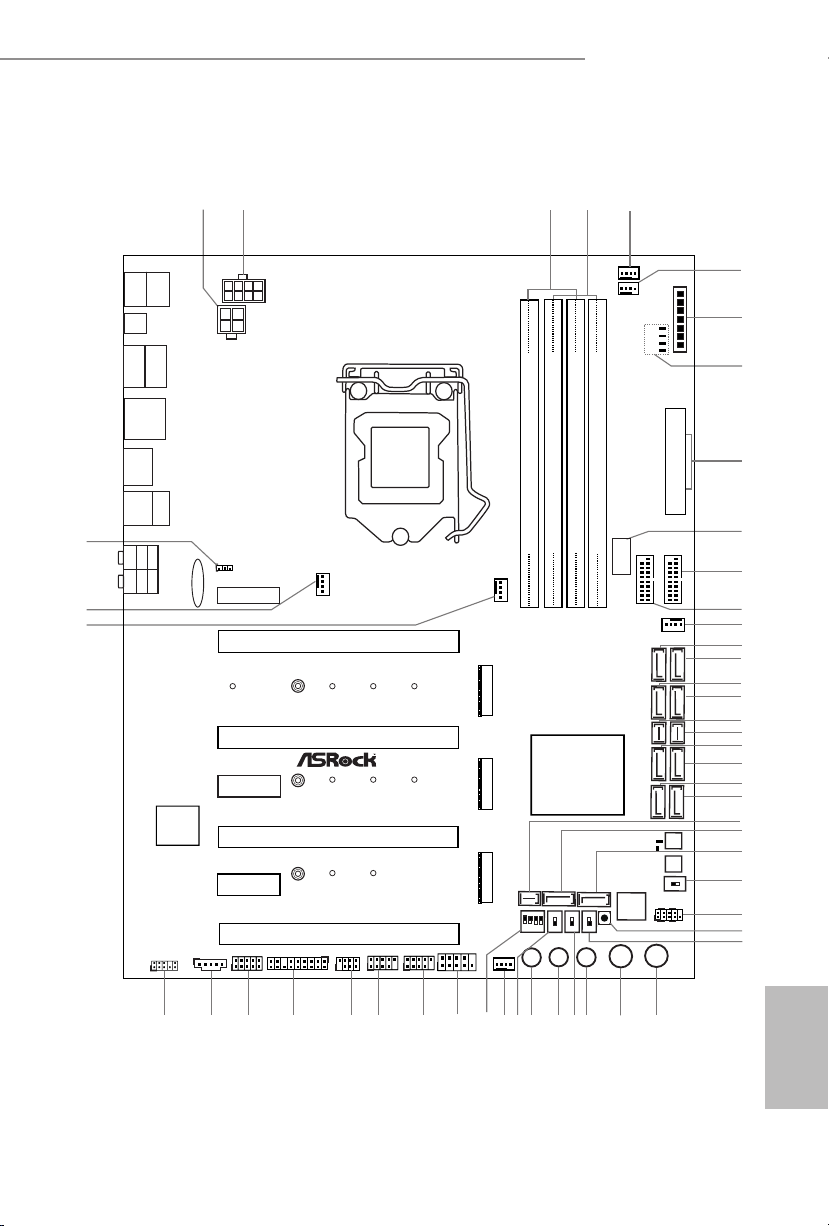
Motherboard Layout
Intel
Z170
ATX12V1
ATX12V2
1
SPK_PLED1
CPU_FAN1
CHA_FAN3
Purity
Sound 3
TM
Ultra M.2
PCIe Gen3x4
BIOS_A_LED
128Mb
BIOS
128Mb
BIOS
BIOS_B_LED
CLRMOS1
1
CT2CT3CT5
VOL_CO N1
CHA_FAN1
1
TPMS1
USB 3.1
T: USB31_TA_1
B: USB31_TC_1
CT1
DDR 4_A1 (6 4 bit, 28 8-pin m odule )
DDR 4_A2 (6 4 bit, 28 8-pin m odule )
DDR 4_B1 (6 4 bit, 28 8-pin m odule )
DDR 4_B2 (6 4 bit, 28 8-pin m odule )
ATXP WR1
Reset
Power
PANEL1
HDLED RESET
PLED PWRBTN
1
CHA_FAN2
Top:
Central/B ass
Top:
LINE IN
Clr
CMOS
USB 3.0
T: USB1
B: USB2
Top:
RJ-45
USB 3.0
T: USB3
B: USB4
Center:
REAR SPK
Center:
FRONT
Bottom:
Optical
SPDIF
Bottom:
MIC IN
+
CHA_FAN4
CPU_FAN2
3
4
-
20
22
19
USB 2.0
T: USB1
B: USB2
ON
1 2 3 4
ON
OFF
USB3_7_8
31
USB5_6
1
USB3_4
1
BIOS_SEL 1
AB
PS2
Keybo ard
/Mous e
MENU
ON
OFF
SATA_EXP1
SATA_EXP0
SATA3_A3
SATA3_A4
SATA3_0
SATA3_2
SATA3_1
SATA3_3
COM1
1
1
HD_AUDIO1
1
T B2
T B1
1
PCIE3
PCIE2
PCIE4
Z170 OC Formula
PCIE6
M2_1
PCIE1
PCIE5
ON
OFF
LN2MODE1
SWITCH1
2
5
1
9
7
8
6
13
11
10
12
21
23
27
24
25
26
14
15
16
18
17
32
33
343536
38
41
42
43
44
46
47
30
28
37
39
40
48
49
50
USB3_5_6
SATA3_A1
SATA3_A2
M2_2
M2_3
45
CT2CT3CT1
CT2CT3
MINI_PCIE1
DISP LAY1
HDM I1
CPU
DRAM
VGA
BOOT
USB3_9
Vertica l Type A
USB 3.0
29
DIRKEY1
Dr.
Debug
BIOS_A1
BIOS_B1
SLOWMODE1
CT4
CT4
CT4
CMOS
Battery
SATA3_4SATA3_5
SATA_EXP2
XMP_ON1
Z170 OC Formula
English
1

English
No. Description
1 ATX 12V Power Connector (ATX12V2)
2 ATX 12V Power Connector (ATX12V1)
3 2 x 288-pin DDR3 DIMM Slots (DDR3_A1, DDR3_B1)
4 2 x 288-pin DDR3 DIMM Slots (DDR3_A2, DDR3_B2)
5 Chassis Fan Connector (CHA_FAN4)
6 CPU Fan Connector (CPU_FAN2)
7 V-ProbeTM (VOL _CO N1)
8 Post Status Checker (PSC)
9 ATX Power Connector (ATXPWR1)
10 Vertical Type A USB 3.0 (USB3_9)
11 USB 3.0 Header (USB3_5_6)
12 USB 3.0 Header (USB3_7_8)
13 Chassis Fan Connector (CHA_FAN1)
14 SATA3 Connector (SATA3_0)
15 SATA3 Connector (SATA3_2)
16 SATA3 Connector (SATA3_1)
17 SATA3 Connector (SATA3_3)
18 SATA Express Connector (SATA_EXP0)
19 SATA Express Connector (SATA_EXP1)
20 SATA3 Connector (SATA3_A3)
21 SATA3 Connector (SATA3_ A4)
22 SATA3 Connector (SATA3_A1)
23 SATA3 Connector (SATA3_A2)
24 SATA Express Connector (SATA_EXP2)
25 SATA3 Connector (SATA3_5)
26 SATA3 Connector (SATA3_4)
27 BIOS Selection Switch (BIOS_SEL1)
28 System Panel Header (PANEL1)
29 Direct Key Button (DIRKEY1)
30 XMP Switch (XMP_ON1)
31 Power Switch (PWR)
32 Reset Switch (RST)
33 Rapid OC Button (+) (PLUS)
2

No. Description
34 Slow Mode Switch (SLOWMODE)
35 Rapid OC Button (–) (MINUS)
36 Menu Button (MENU)
37 LN2 Mode Switch (LN2MODE)
38 Chassis Fan Connector (CHA_FAN2)
39 PCIe ON/OFF Switch (SWITCH1)
40 COM Port Header (COM1)
41 USB 2.0 Header (USB5_6)
42 USB 2.0 Header (USB3_4)
43 Power LED and Speaker Header (SPK_PLED1)
44 TPM Header (TPMS1)
45 underbolt 3 AIC Connector (TB2)
46 underbolt 2 AIC Connector (TB1)
47 Front Panel Audio Header (HD_AUDIO1)
48 CPU Fan Connector (CPU_FAN1)
49 Chassis Fan Connector (CHA_FAN3)
50 Clear CMOS Jumper (CLRMOS1)
Z170 OC Formula
English
3
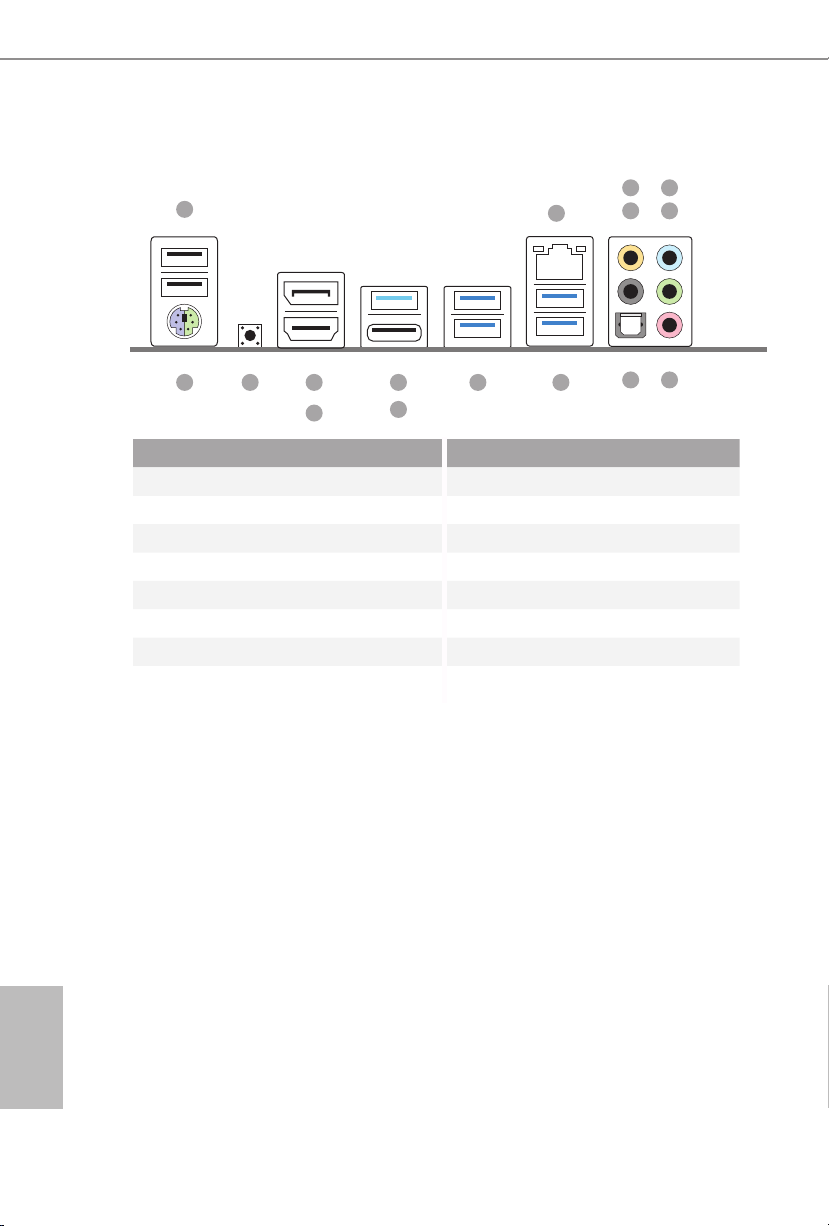
I/O Panel
1
5
2
436
16 913
No. Description No. Description
1 USB 2.0 Ports (USB12) 9 USB 3.0 Ports (USB3_34)
2 LAN RJ-45 Port* 10 USB 3.0 Ports (USB3_12)
3 Central / Bass (Orange) 11 USB 3.1 Type-A Port (USB31_TA_1)
4 Rear Speaker (Black) 12 USB 3.1 Type-C Port (USB31_TC_1)
5 Line In (Light Blue) 13 DisplayPort 1.2
6 Front Speaker (Lime)** 14 HDMI Port
7 Microphone (Pink) 15 Clear CMOS Switch
8 Optical SPDIF Out Port 16 PS/2 Mouse/Keyboard Port
15
14
11
12
10
78
English
4
Z170 OC Formula
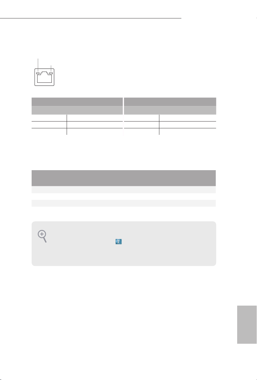
* ere are two LEDs on each LAN port. Plea se refer to the table below for the LAN port LED indications.
ACT/LINK LED
SPEED LED
LAN Por t
Activity / Link LED Speed LED
Status Description Status Description
O No Link O 10Mbps connection
Blinking Data Activity Orange 100Mbps connection
On Link Green 1Gbps connection
** If you use a 2- channel speaker, please connect the speaker’s plug into “Front Speaker Jack”. See the table below
for connection details in accordance with the type of speaker you use.
Audio Output
Channels
Front Speaker
(No. 6)
Rear Speaker
(No. 4)
Central / Bass
(No. 3)
2 V -- -- --
4 V V -- --
6 V V V --
8 V V V V
To enable Multi-Streaming, you need to connect a front panel audio cable to the front
panel audio header. Aer restarting your computer, you will nd the “Mixer” tool on your
system. Please select “Mixer ToolBox” , click “Enable playback multi-streaming”, and
click “ok”. Choose “2CH”, “4CH”, “6CH”, or “8CH” and then you are allowed to select
“Realtek HDA Primary output” to use the Rear Speaker, Central/Bass, and Front Speaker,
or select “Realtek HDA Audio 2nd output” to use the front panel audio.
Line In
(No. 5)
English
5

Chapter 1 Introduction
ank you for purchasing ASRock Z170 OC Formula motherboard, a reliable
motherboard produced under ASRock’s consistently stringent quality control.
It delivers excellent performance with robust design conforming to ASRock’s
commitment to quality and endurance.
Becau se the motherboard specications and the BIOS soware might be updated, the
content of this documentation will be subject to change without notice. In case any modications of this documentation occ ur, the updated version will be available on ASRock’s
website w ithout further notice. If you require technical suppor t related to this motherboard, please visit our website for specic information about the model you are using. You
may nd the l atest VGA cards and CPU support list on ASRock’s website as well . ASRock
website http://www.asrock.com.
1.1 Package Contents
ASRock Z170 OC Formula Motherboard (ATX Form Factor)
•
ASRock Z170 OC Formula Quick Installation Guide
•
ASRock Z170 OC Formula Support CD
•
4 x Serial ATA (SATA) Data Cables (Optional)
•
1 x I/O Panel Shield
•
1 x ASRock Flexible SLI Bridge Connector Cable
•
1 x WiFi Module Bracket
•
2 x Screws for WiFi Module
•
3 x Screws for M.2 Socket
•
English
6

1.2 Specications
Platform
CPU
Chipset
Memory
* Please refer to Memory Support List on ASRock's website for
more information. (http://www.asrock.com/)
Z170 OC Formula
ATX Form Factor
•
Supports 6th Generation Intel® CoreTM i7/i5/i3/Pentium®/
•
Celeron® Processors (Socket 1151)
Digi Power design
•
16 Power Phase design
•
Supports Intel® Turbo Boost 2.0 Technology
•
Supports Intel® K-Series unlocked CPUs
•
Supports ASRock BCLK Full-range Overclocking
•
Supports ASRock Hyper BCLK Engine
•
Intel® Z170
•
Dual Channel DDR4 Memory Technology
•
4 x DDR4 DIMM Slots
•
Supports DDR4 4400+(OC)*/4300(OC)/4266(OC) /4200
•
(OC)/4133(OC)/4000(OC)/3866(OC)/3800(OC)/3733 (OC)/
3666(OC)/3600(OC)/3466(OC)/3400(OC)/3333(OC)/
3300(OC)/3200(OC)/3000(OC)/2933(OC)/2800(OC)/2600
(OC)/2400(OC)/2133 non-ECC, un-buered memory
Max. capacity of system memory: 64GB
•
Supports Intel® Extreme Memory Prole (XMP) 2.0
•
15μ Gold Contact in DIMM Slots
•
Expansion
Slot
4 x PCI Express 3.0 x16 Slots (PCIE1/PCIE2/PCIE4/PCIE6:
•
single at x16 (PCIE1); dual at x8 (PCIE1) / x8 (PCIE4); triple
at x8 (PCIE1) / x4 (PCIE2) / x8 (PCIE4)); quad at x8 (PCIE1)
/ x4 (PCIE2) / x4 (PCIE4) / x4 (PCIE6))
1 x PCI Express 3.0 x1 Slot (PCIE3) (Flexible PCIe)
•
1 x PCI Express 2.0 x1 Slot (PCIE5)
•
1 x Vertical Half-size Mini-PCI Express Slot: For WiFi + BT
•
Module
Supports AMD Quad CrossFireXTM, 4-Way CrossFireXTM,
•
3-Way CrossFireXTM and CrossFireXTM
Supports NVIDIA® Quad SLITM and SLI
•
15μ Gold Contact in VGA PCIe Slot (PCIE1 and PCIE4)
•
TM
English
7

Graphics
Intel® HD Graphics Built-in Visuals and the VGA outputs
•
can be supported only with processors which are GPU
integrated.
Supports Intel® HD Graphics Built-in Visuals : Intel® Quick
•
Sync Video with AVC, MVC (S3D) and MPEG-2 Full
HW Encode1, Intel® InTruTM 3D, Intel® Clear Video HD
Technology, Intel® InsiderTM, Intel® HD Graphics 510/530
Pixel Shader 5.0, DirectX 12
•
Max. shared memory 1792MB
•
Dual graphics output: Support HDMI and DisplayPort 1.2
•
ports by independent display controllers
Supports HDMI with max. resolution up to 4K x 2K
•
(4096x2304) @ 24Hz
Supports DisplayPort 1.2 with max. resolution up to 4K x 2K
•
(4096x2304) @ 24Hz or 4K x 2K (3840x2160) @ 60Hz
Supports Auto Lip Sync, Deep Color (12bpc), xvYCC and
•
HBR (High Bit Rate Audio) with HDMI Port (Compliant
HDMI monitor is required)
Supports Accelerated Media Codecs: HEVC, VP8, VP9
•
Supports HDCP with DVI-D, HDMI and DisplayPort 1.2
•
Ports
Supports Full HD 1080p Blu-ray (BD) playback with HDMI
•
and DisplayPort 1.2 Ports
English
8
Audio
7.1 CH HD Audio with Content Protection (Realtek
•
ALC1150 Audio Codec)
Premium Blu-ray Audio support
•
Supports Surge Protection (ASRock Full Spike Protection)
•
Supports Purity SoundTM 3
•
- Nichicon Fine Gold Series Audio Caps
- 115dB SNR DAC with Dierential Amplier
- TI® NE5532 Premium Headset Amplier (Supports up to
600 Ohms headsets)
- Pure Power-In
- Direct Drive Technology
- PCB Isolate Shielding
Supports DTS Connect
•

LAN
Rear Panel
I/O
Z170 OC Formula
Gigabit LAN 10/100/10 00 Mb/s
•
Giga PHY Intel® I219V
•
Supports Wake-On-LAN
•
Supports Lightning/ESD Protection (ASRock Full Spike
•
Protection)
Supports Energy Ecient Ethernet 802.3az
•
Supports PXE
•
1 x PS/2 Mouse/Keyboard Port
•
1 x HDMI Port
•
1 x DisplayPort 1.2
•
1 x Optical SPDIF Out Port
•
2 x USB 2.0 Ports (Supports ESD Protection (ASRock Full
•
Spike Protection))
1 x USB 3.1 Type-A Port (10 Gb/s) (ASMedia ASM1142)
•
(Supports ESD Protection (ASRock Full Spike Protection))
1 x USB 3.1 Type-C Port (10 Gb/s) (ASMedia ASM1142)
•
(Supports ESD Protection (ASRock Full Spike Protection))
4 x USB 3.0 Ports (Intel® Z170) (Supports ESD Protection
•
(ASRock Full Spike Protection))
1 x RJ-45 LAN Port with LED (ACT/LINK LED and SPEED
•
LE D)
1 x Clear CMOS Switch
•
HD Audio Jacks: Rear Speaker / Central / Bass / Line in /
•
Front Speaker / Microphone
Storage
6 x SATA3 6.0 Gb/s Connectors by Intel® Z170, support
•
RAID (RAID 0, RAID 1, RAID 5, RAID 10, Intel Rapid Storage Technology 14 and Intel Smart Response Technology),
NCQ, AHCI and Hot Plug
4 x SATA3 6.0 Gb/s Connectors by ASMedia ASM1061, sup-
•
port NCQ, AHCI and Hot Plug
3 x SATA Express 10 Gb/s Connectors*
•
* Support to be announced
* M2_1, SATA3_0, SATA3_1 and SATA_EXP0 share lanes. If
either one of them is in use, the others will be disabled.
* M2_2, SATA3_2, SATA3_3 and SATA_EXP1 share lanes. If
either one of them is in use, the others will be disabled.
* M2_3, SATA3_4, SATA3_5 and SATA_EXP2 share lanes. If
either one of them is in use, the others will be disabled.
English
9

English
Connector
3 x Ultra M.2 Sockets, supports M.2 SATA3 6.0 Gb/s module
•
and M.2 PCI Express module up to Gen3 x4 (32 Gb/s)
* Supports 3 x ASRock U.2 Kits
1 x COM Port Header
•
1 x TPM Header
•
1 x Power LED and Speaker Header
•
2 x CPU Fan Connectors (4-pin) (Smart Fan Speed Control)
•
4 x Chassis Fan Connectors (4-pin) (Smart Fan Speed
•
Control)
1 x 24 pin ATX Power Connector
•
1 x 8 pin 12V Power Connector (Hi-Density Power
•
Connec tor)
1 x 4 pin 12V Power Connector (Hi-Density Power
•
Connec tor)
1 x Front Panel Audio Connector
•
1 x underbolt 2 AIC Connector (5-pin)
•
1 x underbolt 3 AIC Connector (10-pin)
•
* Only one underbolt AIC Card is supported.
2 x USB 2.0 Headers (Support 4 USB 2.0 ports) (Supports
•
ESD Protection (ASRock Full Spike Protection))
2 x USB 3.0 Headers (Supports 4 USB 3.0 ports) (Supports
•
ESD Protection (ASRock Full Spike Protection))
1 x Vertical Type A USB 3.0
•
1 x Dr. Debug with LED
•
1 x Power Switch with LED
•
1 x Reset Switch with LED
•
V-ProbeTM: 1 x 7-set of onboard voltage measurement points
•
laid
Rapid OC Buttons: +/- buttons to adjust OC frequency
•
1 x Menu Button
•
1 x PCIe ON/OFF Switch
•
1 x Post Status Checker (PSC)
•
1 x Slow Mode Switch
•
1 x LN2 Mode Switch
•
1 x BIOS Selection Switch
•
1 x XMP Switch
•
1 x Direct Key Button
•
10

BIOS
Feature
Hardware
Monitor
OS
Z170 OC Formula
2 x 128Mb AMI UEFI Legal BIOS with multilingual GUI
•
support (1 x Main BIOS and 1 x Backup BIOS)
Supports Secure Backup UEFI Technology
•
ACPI 1.1 Compliant wake up events
•
SMBIOS 2.3.1 Support
•
CPU, GT_CPU, DRAM, VPPM, PCH 1.0V, VCCIO,
•
VCCPLL, VCCSA Voltage Multi-adjustment
CPU/Chassis temperature sensing
•
CPU/Chassis Fan Tachometer
•
CPU/Chassis Quiet Fan (Auto adjust chassis fan speed by
•
CPU temperature)
CPU/Chassis Fan multi-speed control
•
Voltage monitoring: +12V, +5V, +3.3V, CPU Vcore, GT_CPU,
•
DRAM, VPPM, PCH 1.0V, VCCIO, VCCSA
Microso® Windows® 10 64-bit / 8.1 64-bit / 7 32-bit / 7 64-
•
bit
* To install Windows® 7 OS, a modied installation disk with
xHCI drivers packed into the ISO le is required. Please refer to
page 217 for more detailed instructions.
* For the updated Windows® 10 driver, please visit ASRock’s
website for details: http://www.asrock.com
FCC, CE, WHQL
Certications
* For detailed product information, please v isit our website: http://www.asrock.com
Please realize that there is a certain risk involved with overclocking, including adjusting
the setting in the BIOS , applying Untied Overclocking Technology, or using third-party
overclocking tools. Overclocking may aect your system’s stability, or even cau se damage to
the components and devices of your system. It should be done at your own r isk and expense.
We are not responsible for possible damage caused by overclocking.
•
ErP/EuP Ready (ErP/EuP ready power supply is required)
•
English
11

Chapter 2 Installation
is is an ATX form factor motherboard. Before you install the motherboard, study
the conguration of your chassis to ensure that the motherboard ts into it.
Pre-installation Precautions
Take note of the following precautions before you install motherboard components
or change any motherboard settings.
Make sure to unplug the power cord before installing or removing the motherboard
•
components. Failure to do so may cause physical injuries and damages to motherboard
components.
In order to avoid damage from static electricity to the motherboard’s components,
•
NEVER place your motherboard directly on a carpet. Also remember to use a grounded
wrist strap or touch a safety grounded object before you handle the components.
Hold components by the edges and do not touch the ICs.
•
Whenever you uninstall any components, place them on a grounded anti-static pad or
•
in the bag that comes with the components.
When placing screws to secure the motherboard to the chassis, please do not over-
•
tighten the screws! Doing so may damage the motherboard.
English
12
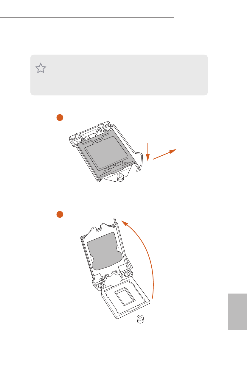
2.1 Installing the CPU
1. Before you insert the 1151-Pin CPU into the socket, please check if the PnP cap is on the
socket, if the CPU sur face is unclean, or if the re are any bent pins in the socket. Do not
force to in sert the CPU into the socket if above situation is found. Otherwise, the CPU
will be seriously damaged.
2. Unplug all power cables be fore installing the CPU.
1
Z170 OC Formula
A
B
2
English
13
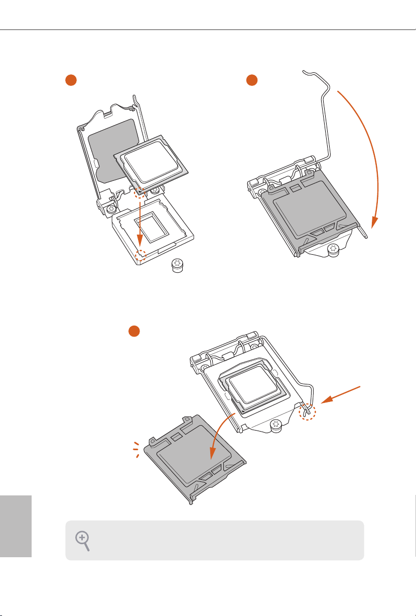
3
4
5
English
14
Please save and replace the cover if the processor is removed. e cove r must be placed if
you wish to return the motherboard for ae r service.
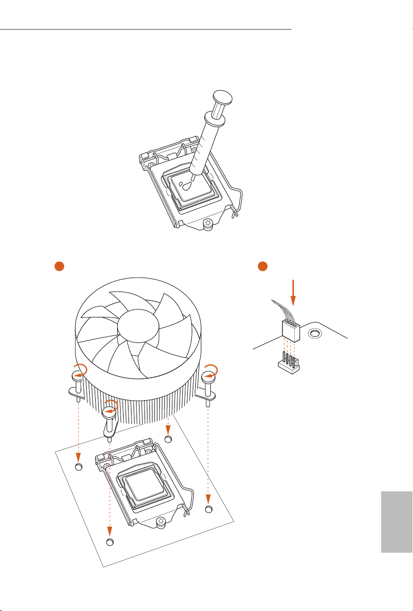
2.2 Installing the CPU Fan and Heatsink
1 2
Z170 OC Formula
FAN
CPU_
English
15
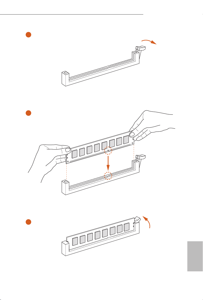
2.3 Installing Memory Modules (DIMM)
is motherboard provides four 288-pin DDR4 (Double Data Rate 4) DIMM slots,
and supports Dual Channel Memory Technology.
1. For dual channel conguration, you always need to install identical (the same brand,
speed , size and chip-type) DDR4 DIMM pairs.
2. It is unable to activate Dual Channel Memory Technology with only one or three memory
module installed.
3. It is not allowed to install a DDR, DDR2 or DDR3 memory module into a DDR4 slot;
otherwise, this motherboard and DI MM may be damaged.
Dual Channel Memory Conguration
If you install two memory modules, make sure to install DIMMs into DDR4_A2
and DDR4_B2 slots.
Priority DDR4_A1 DDR4_A2 DDR4_B1 DDR4_B2
1 Populated Populated
2 Populated Populated Populated Populated
e DIMM only ts in one correct orientation. It will cause permanent damage to the
motherboard and the DIMM if you force the DIMM into the slot at incorrect orientation .
English
16
Z170 OC Formula
1
2
3
English
17

2.4 Expansion Slots (PCI Express Slots)
ere are 6 PCI Express slots and 1 mini-PCI Express slot on the motherboard.
Before installing an expansion card, plea se make sure that the power supply is switched o
or the power cord is unplugged. Please read the documentation of the expansion card and
make necessary hardware settings for the card before you start the installation.
PCIe slots:
PCIE1 (PCIe 3.0 x16 slot) is used for PCI Express x16 lane width graphics cards.
PCIE2 (PCIe 3.0 x16 slot) is used for PCI Express x4 lane width graphics cards.
PCIE3 (PCIe 3.0 x1 slot) is used for PCI Express x1 lane width cards.
PCIE4 (PCIe 3.0 x16 slot) is used for PCI Express x8 lane width graphics cards.
PCIE5 (PCIe 2.0 x1 slot) is used for PCI Express x1 lane width cards.
PCIE6 (PCIe 3.0 x16 slot) is used for PCI Express x4 lane width graphics cards.
mini-PCIe slot:
MINI_PCIE1 (mini-PCIe slot) is used for WiFi module.
English
18

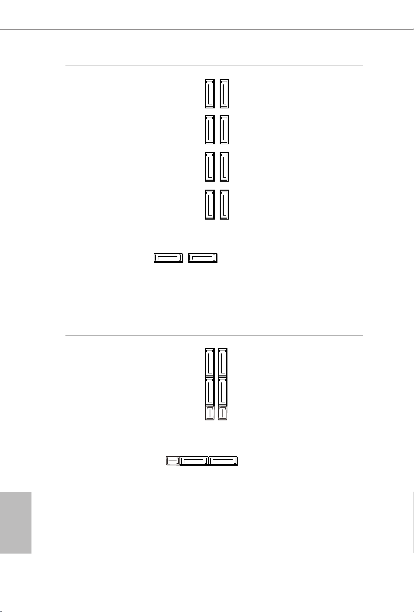
PCIe Slot Congurations
Z170 OC Formula
PCIE1 PCIE2 PCIE4 PCIE6
Single Graphics
Card
Two Graphics
Cards in
CrossFireXTM or
SLITM Mode
ree Graphics
Cards in 3-Way
CrossFireXTM
Mode
Four Graphics
Cards in 4-Way
CrossFireXTM
Mode
For a better thermal environment, please connect a chassis fan to the motherboard ’s chassis fan connector (CHA_FAN1, CHA_FAN2, CHA_FAN3 or CHA_ FAN4) when using
multiple graphics cards.
x16 N/A N/A N/A
x8 N/A x8 N/A
x8 x4 x8 N/A
x8 x4 x4 x4
19
English
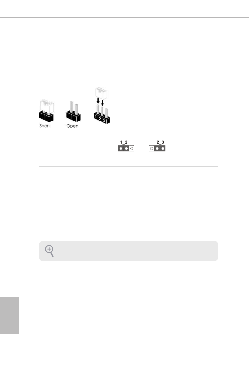
2.5 Jumpers Setup
e illustration shows how jumpers are setup. When the jumper cap is placed on
the pins, the jumper is “Short”. If no jumper cap is placed on the pins, the jumper
is “Open”. e illustration shows a 3-pin jumper whose pin1 and pin2 are “Short”
when a jumper cap is placed on these 2 pins.
Clear CMOS Jumper
(C LRC MO S1)
(see p.1, No. 50)
CLRCMOS1 allows you to clear the data in CMOS. To clear and reset the system
parameters to default setup, please turn o the computer and unplug the power
cord from the power supply. Aer waiting for 15 seconds, use a jumper cap to
short pin2 and pin3 on CLRCMOS1 for 5 seconds. However, please do not clear
the CMOS right aer you update the BIOS. If you need to clear the CMOS when
you just nish updating the BIOS, you must boot up the system rst, and then shut
it down before you do the clear-CMOS action. Please be noted that the password,
date, time, and user default prole will be cleared only if the CMOS battery is
removed.
Clear CMOSDefault
English
20
e Clear CMOS Switch has the same function as the Cl ear CMOS jumper.
2.6 Onboard Headers and Connectors
1
+5V
DUMMY
PLED+
PLED+
PLED-
DUMMY
SPEAKER
Onboard headers and connectors are NOT jumpers. Do NOT place jumper caps over these
heade rs and connectors. Placing jumper caps over the headers and connectors will cause
permanent damage to the motherboard.
Z170 OC Formula
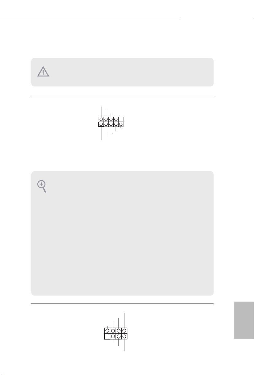
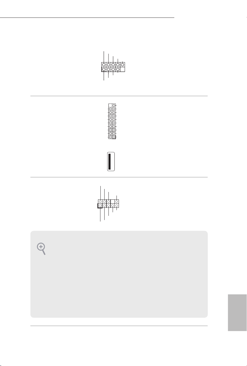
System Panel Header
(9-p in PA NEL1)
(see p.1, No. 28)
PWRBTN (Power Switch):
Connec t to the power switch on the cha ssis front panel. You may congure the way to turn
o your system using the power switch.
RESET (Reset Sw itch):
Connec t to the reset switch on the cha ssis front panel. Press the reset switch to restart the
computer if the computer freezes and fails to perform a normal restart.
PLED (Syste m Power LED):
Connec t to the power status indicator on the chassis front panel. e LED i s on when the
system is operating. e LED keeps blinking when the system is in S1/S3 sleep state. e
LED is o when the system is in S4 sleep state or powered o (S5).
HDLED (Ha rd Drive Activity LED):
Connec t to the hard drive activity LED on the cha ssis front panel. e LED is on when the
hard drive is reading or writing data.
e front panel design may dier by chassis. A f ront panel module mainly consists of power
switch, reset switch, power LED, hard drive activity LED, speaker and etc. When connecting your chassis front panel module to this header, make sure the wire assignme nts and the
pin assignment s are matched cor rectly.
1
PLED+
PLED-
HDLED-
HDLED+
PWRBTN#
GND
RESET#
GND
GND
Connect the power
switch, reset switch and
system status indicator on
the chassis to this header
according to the pin
assignments below. Note
the positive and negative
pins before connecting
the cables.
Power LED and Speaker
Header
(7-pin SPK_PLED1)
(see p.1, No. 43)
Please connect the
chassis power LED and
the chassis speaker to this
header.
English
21
Serial ATA3 Connectors
(SATA3_0
see p.1, No. 14)
(SATA3_1:
see p.1, No. 16)
(SATA3_2:
see p.1, No. 15)
(SATA3_3:
see p.1, No. 17)
(SATA3_4:
see p.1, No. 26)
(SATA3_5:
see p.1, No. 25)
(SATA3_A1
see p.1, No. 22)
(SATA3_A2
see p.1, No. 23)
(SATA3_A3:
see p.1, No. 20)
(SATA3_A4:
see p.1, No. 21)
SATA3_4SATA3_5
SATA3_0SATA3_1
SATA3_A3SATA3_A1
ese ten SATA3
connectors support SATA
SATA3_2SATA3_3
data cables for internal
storage devices with up
to 6.0 Gb/s data transfer
rate. e SATA3_0,
SATA3_1 are shared with
the SATA_EXP0. e
SATA3_2, SATA3_3 are
SATA3_A4SATA3_A2
shared with the SATA_
EXP1. e SATA3_4,
SATA3_5 are shared with
the SATA_EXP2.
To minimize the boot
time, use Intel® Z170
SATA ports (SATA3_0)
for your bootable devices.
English
22
Serial ATA Express
Connectors
(SATA_EX P_0:
see p.1, No. 18)
(SATA_EX P_1:
see p.1, No. 19)
(SATA_EX P_2:
see p.1, No. 24)
SATA3_0
SATA3_1
SATA_EXP0
Please connect either
SATA or PCIe storage
SATA3_2
devices to these
connectors.
SATA3_3
*SATA_EXP0 is shared
with the SATA3_0,
SATA3_1 and the M2_1;
SATA_EXP1
SATA_EXP1 is shared
SATA3_4SATA3_5SATA_EXP2
with the SATA3_2,
SATA3_3 and the M2_2;
SATA_EXP2 is shared
with the SATA3_4,
SATA3_5 and the M2_3.
Z170 OC Formula
J_SENSE
OUT2_L
1
MIC_RET
PRESENCE#
GND
OUT2_R
MIC2_R
MIC2_L
OUT_RET
DUMMY
GND
GND
P+
P-
USB_PWR
P+
P-
USB_PWR
1
USB 2.0 Headers
(9-pin USB3_4)
(see p.1, No. 42)
(9-pin USB5_6)
(see p.1, No. 41)
USB 3.0 Headers
(19-pin USB3_5_6)
(see p.1, No. 11)
(19-pin USB3_7_8)
(see p.1, No. 12)
(USB3_9)
(see p.1, No. 10)
Front Panel Audio Header
(9-pin HD_AU DIO1)
(see p.1, No. 47)
Vbus
IntA_PA_SSRX-
IntA_PA_SSRX+
GND
IntA_PA_SSTX-
IntA_PA_SSTX+
GND
IntA_PA_D-
IntA_PA_D+
VbusVbus
IntA_PB_SSRX-
IntA_PB_SSRX+
GND
IntA_PB_SSTX-
IntA_PB_SSTX+
GND
IntA_PB_D-
IntA_PB_D+
Dummy
1
Besides two USB 2.0 ports
on the I/O panel, there
are two headers on this
motherboard. Each USB
2.0 header can support
two ports.
Besides six USB 3.0 ports
on the I/O panel, there
are two headers and one
port on this motherboard.
Each USB 3.0 header can
support two ports.
is header is for
connecting audio devices
to the front audio panel.
1. High Denition Audio supports Jack Sensing, but the panel wire on the chassis must support HDA to function correctly. Please follow the instructions in our manual and chassis
manual to install your system.
2. If you use an AC’97 audio panel, please install it to the front panel audio header by the
steps below:
A. Connect Mic_ IN (MIC) to MIC2_L.
B. Conne ct Audio_R (RIN) to OUT2_R and Audio_L (LIN) to OUT2_L.
C. Connect Ground (GND) to Ground (GND).
D. MIC_ RET and OUT_RET are for the HD audio panel only. You don’t need to connect
them for the AC’97 audio panel.
E. To activate the front mic, go to the “FrontMic” Tab in the Realtek Control panel and
adjust “Recording Volume”.
English
23
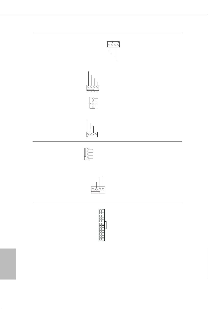
Chassis Fan Connectors
F
4 3 2 1
GND
OL
1
2
3
4
GND
GND
OL
FAN_SPEED_CONTROL
1 2 3 4
1
(4-pin CHA_FAN1)
(see p.1, No. 13)
AN_SPEED_CONTROL
CHA_FAN_SPEED
FAN_VOLTAGE
Please connect fan cables
to the fan connectors and
match the black wire to
the ground pin.
(4-pin CHA_FAN2)
(see p.1, No. 38)
(4-pin CHA_FAN3)
(see p.1, No. 49)
(4-pin CHA_FAN4)
(see p.1, No. 5)
CPU Fan Connectors
(4-pin CPU_FAN1)
(see p.1, No. 48)
(4-pin CPU_FAN2)
(see p.1, No. 6)
ATX Power Connector
(24-pin ATXPW R1)
(see p.1, No. 9)
FAN_VOLTAGE
FAN_SPEED
FAN_VOLTAGE
FAN_SPEED
GND
2
FAN_VOLTAGE
CPU_FAN_SPEED
3
FAN_SPEED_CONTROL
4
CPU_FAN_SPEED
FAN_VOLTAGE
GND
12
1
FAN_SPEED_CONTR
FAN_VOLTAGE
CHA_FAN_SPEED
FAN_SPEED_CONTR
FAN_SPEED_CONTROL
24
13
is motherboard
provides a 4-Pin CPU fan
(Quiet Fan) connector.
If you plan to connect a
3-Pin CPU fan, please
connect it to Pin 1-3.
is motherboard provides a 24-pin ATX power
connector. To use a 20-pin
ATX power supply, please
plug it along Pin 1 and Pin
13.
English
24
Z170 OC Formula
1
1
5
1
8
I2C_DATA
GND
SLP_S3#
FRC_PWR
DUMMY
PLUG_EVENT
SLP_S4#
IRQ
GND
I2C_CLOCK
1
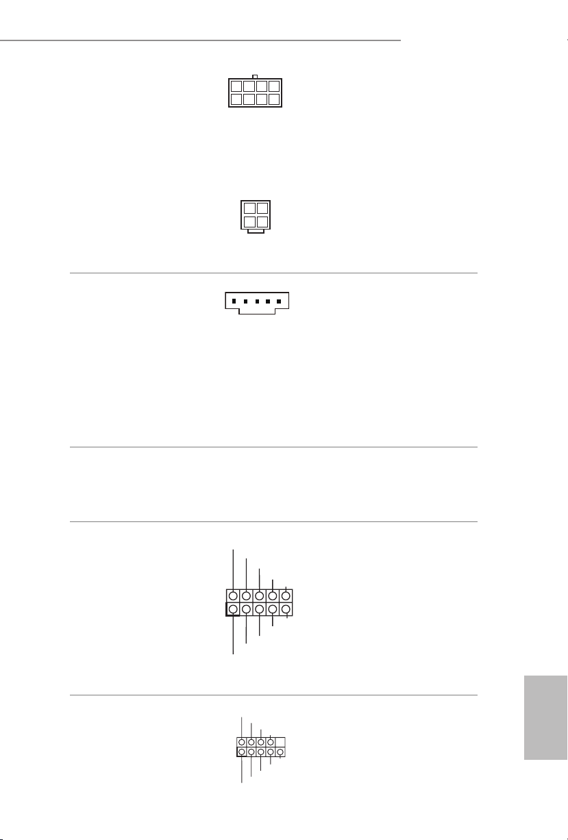
ATX 12V Power
Connectors
(8-pin ATX12V1)
(see p.1, No. 2)
is motherboard
provides an 8-pin ATX
12V power connector and
a 4-pin ATX 12V power
connector. To use a 4-pin
ATX power supply, please
plug it along Pin 1 and Pin
5.
(4-pin ATX12V2)
(see p.1, No. 1)
*e 4-pin ATX 12V
power connector is used
to supply additional power
to the motherboard.
underbolt AIC
Connector
(5-pin TBT1)
(see p.1, No. 46)
Please connect a underbolt™
add-in card (AIC) to this
connector via the GPIO cable.
*Please install the underbolt™
AIC card to PCIE2 (default
slot).
*Only one underbolt AIC
Card is supported on this
motherboard.
*e type of underbolt AIC connector depends on the underbolt AIC cable. If your
underbolt AIC cable supports 5-pin, please install it to 5-pin TBT1 connector. If your
underbolt AIC cable supports 10-pin, please install it to 10-pin TBT2 connector.
underbolt AIC
Connector
(10-pin TBT2)
(see p.1, No. 45)
Serial Port Header
(9-pin COM1)
(see p.1, No. 40)
RRXD1
DDTR#1
TTXD1
DDCD#1
DDSR#1
CCTS#1
RRTS#1
GND
RRI#1
Please connect a underbolt™
add-in card (AIC) to this
connector via the GPIO cable.
*Please install the underbolt™
AIC card to PCIE2 (default
slot).
*Only one underbolt AIC
Card is supported on this
motherboard.
is COM1 header
supports a serial port
module.
English
25
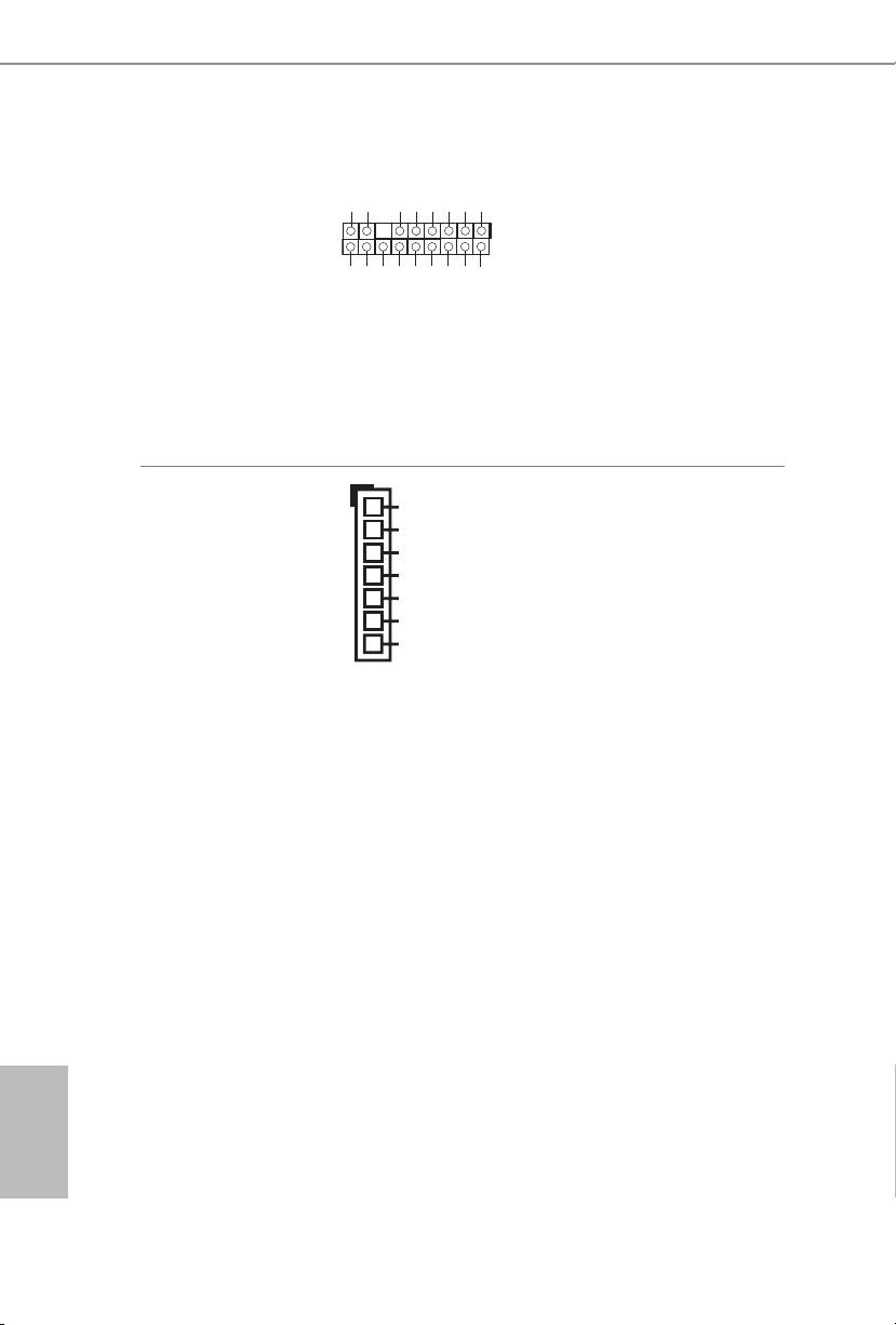
TPM Header
#
(17-pi n TPMS1)
(see p.1, No. 44)
is connector supports Trusted
GN D
LAD 0
LAD 3
+3 V
PC IRST
+3V S B
D
GN
GN D
SER IRQ #
S_P WRDW N #
FRA ME
GN D
LAD 1
LAD 2
SMB _CLK _MAI N
Platform Module (TPM) system,
PC ICL K
which can securely store keys,
1
digital certicates, passwords,
and data. A TPM system also
helps enhance network security,
protects digital identities, and
ensures platform integrity.
English
V-Probe
(7-pin VOL_
CO N1)
(see p.1, No. 7)
TM
1
1.0V PCH
VCCSA
VCCM
CPU GT
VCCIO
VCORE
GND
Users are able to measure
onboard components
voltage.
PIN1:
1.0V PCH:
PC H Vol tage
PIN2:
VCCSA:
CPU SYSTEM AGENT
VOLTAGE
PIN3:
VCCM:
DRAM VOLTAGE
PIN4
:
CPU GT:
CPU GRAPHIC
VOLTAG E
PIN5
:
VCCIO: CPU IO
VOLTAG E
PIN6
:
VCORE :
CPU CORE VOLTAGE
26
PIN7
GND
:
Z170 OC Formula
+
-
2.7 Smart Switches
e motherboard has twelve smart switches: Power Switch, Reset Switch, Clear
CMOS Switch, Rapid OC Buttons, Menu Button, PCIe ON/OFF Switch, Slow Mode
Switch, BIOS Selection Switch, LN2 Mode Switch, Direct Key Button and XMP
Switch.
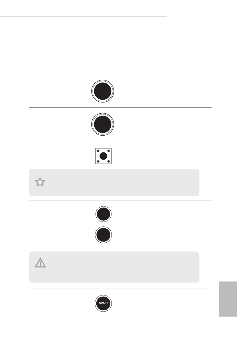
Power Switch
(PWR)
(see p.7, No. 31)
Reset Switch
(RST)
(see p.7 No. 32)
Clear CMOS Switch
(C LRC BT N1)
(see p.10, No. 15)
is function is workable only when you power o your computer and unplug the power
supp ly.
+ / - Rapid OC
Buttons
(PLUS: see p.7, No.
33)
(MINUS: see p.7, No.
35)
Power
Reset
Power Switch allows users to
quickly turn on/o the system.
Reset Switch allows users to
quickly reset the system.
Clear CMOS Switch allows
users to quickly clear the
CMOS values.
+ / - Rapid OC Buttons allow
users to quickly and easily
adjust OC frequency in Rapid
OC.
is overclocking behavior depends on the system cong uration, such a s memory capability, thermal solution, etc. Overclocking may aect your system stability, or even cause damage to the component s and devices. We are not responsible for possible damage caused by
overc locking.
Menu Button
(MENU: see p.7, No.
36)
MENU
Use MENU Button in Rapid
OC to quickly toggle among
various overclocking options,
such as BCLK, Ratio and
Cache Ratio.
English
27
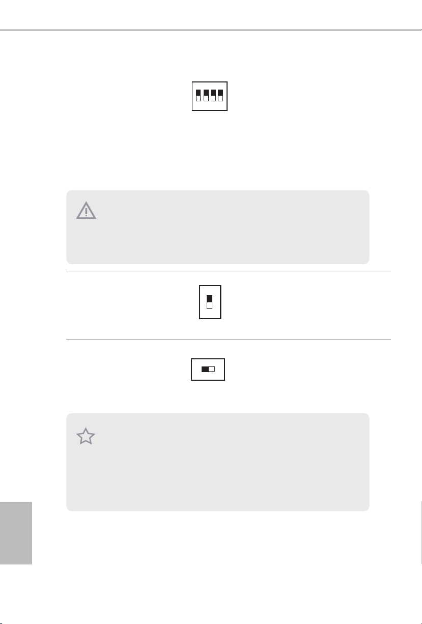
PCIe ON/OFF
AB
Switch
(SWITCH1)
(see p.1, No. 39)
ON
1 2 3 4
1: PCIE1
2: PCIE2
3: PCIE4
4: PCIE6
PCIe ON/OFF Switch allows
you to enable and disable the
corresponding PCIE x16 slots.
When one of the installed
PCIE x16 cards is out of order,
you can use PCIe ON/OFF
Switch to nd out the faulty
one just with a single click
without removing the cards.
1. Make sure that you power o the system be fore changing the switch.
2. When you turn o PCIe ON/OFF switch, your PCIE card could be burnt if it was poorly
designed. For more information about your card ’s spec ications please contact the card’s
ve ndor.
3. PCIe ON/OFF switch is for debug only. If you do not want to u se your PCIE card, please
remove it f rom the motherboard.
English
Slow Mode Switch
(SLOWMODE1)
(see p.1, No. 34)
BIOS Selection
Switch
(BIOS_SEL1)
(see p.1, No. 27)
is motherboard has two BIOS chips, a primary BIOS (BIOS_A) and a ba ckup BIOS (BIOS_
B), which enhances the safety and stability of your system. Normally, the system will work
on the primary BIOS . However, if the primary BIOS is corrupted or damaged, just ip the
BIOS Selection Switch to “B”, then the backup BIOS will take over on the next system boot.
Aer that, use “Secure Backup UEFI” in the UEFI Setup Utility to duplicate a working copy
of the BIOS les to the primary BIOS to ensure normal system operation. For safety issues,
users are not able to update the backup BIOS manually. Users may refer to the BIOS LEDs
(BIOS_ A_LED or BIOS_B_ LED) to identify which BIOS is currently activated.
ON
OFF
If Slow Mode is on, the
processor runs at lowest frequenc y.
BIOS Selection Switch allows
the system to boot from either
BIOS A or BIOS B.
28
 Loading...