

Page 1

®
Release 33 STANDARD
1.5
February 2015
Touchstone
TR3300-AC 802.11ac Wireless
Router
User Guide
Page 2

TR3300-AC 802.11ac Wireless Router User Guide
Release 33 STANDARD 1.5
ARRIS Copyrights and Trademarks
©ARRIS Enterprises, Inc. 2015 All rights reserved. No part of this publication may be
reproduced in any form or by any means or used to make any derivative work (such as
translation, transformation, or adaptation) without written permission from ARRIS
Enterprises, Inc. (“ARRIS”). ARRIS reserves the right to revise this publication and to
make changes in content from time to time without obligation on the part of ARRIS to
provide notification of such revision or change.
ARRIS and the ARRIS logo are all trademarks of ARRIS Enterprises, Inc. Other
trademarks and trade names may be used in this document to refer to either the entities
claiming the marks and the names of their products. ARRIS disclaims proprietary
interest in the marks and names of others.
ARRIS provides this guide without warranty of any kind, implied or expressed, including,
but not limited to, the implied warranties of merchantability and fitness for a particular
purpose. ARRIS may make improvements or changes in the product(s) described in this
manual at any time.
The capabilities, system requirements and/or compatibility with third-party products
described herein are subject to change without notice.
Patent Notice
Protected under one or more of the following U.S. patents: http://www.arris.com/legal
Other patents pending.
Page 3

Table of Contents
Chapter 1. Overview.............................................................................. 6
Introduction.................................................................................................6
Chapter 2. Safety Requirements ............................................................... 7
FCC Part 15 .................................................................................................7
RF Exposure ..........................................................................................8
Industry Canada Compliance .............................................................................8
For Mexico...................................................................................................9
Chapter 3. Product Overview .................................................................. 10
About The Wireless Router ............................................................................. 10
What's in the Box?........................................................................................ 10
Items You Need........................................................................................... 10
System Requirements ................................................................................... 11
Recommended Hardware ........................................................................ 11
Windows ............................................................................................ 11
MacOS ............................................................................................... 11
Linux/other Unix .................................................................................. 11
About this Manual ........................................................................................ 11
What About Security? ................................................................................... 12
Chapter 4. Installing the Wireless Router ................................................... 13
Front Panel................................................................................................ 13
Indicator Lights for the TR3300-AC ................................................................... 14
Rear Panel................................................................................................. 15
Selecting an Installation Location..................................................................... 15
Desktop Mounting Instructions.................................................................. 16
Factors Affecting Wireless Range .............................................................. 16
Ethernet or Wireless?.................................................................................... 17
Connecting the Wireless Router ....................................................................... 18
Configuring the Wireless Connection ................................................................. 18
Chapter 5. Basic Configuration ................................................................ 19
Accessing the Configuration Interface ............................................................... 19
Configuring the Wireless Network .................................................................... 20
Enabling or Disabling the Wireless Network.................................................. 20
Changing the Login Password ................................................................... 20
Changing the Default Wireless Network Name (SSID) ...................................... 21
Configuring Wi-Fi Protected Setup (WPS) .................................................... 21
Setting Up the WAN Connection................................................................ 22
Release 33 STANDARD 1.5 February 2015 TR3300-AC 802.11ac Wireless Router User Guide 3
Page 4

Chapter 6. Advanced Configuration Options................................................ 23
LAN Setup – Configuring DHCP ......................................................................... 23
LAN Setup – Adding and Deleting DHCP Clients.............................................. 24
LAN Setup – Selecting the NAT Mode ................................................................. 24
Wireless Setup – Setting the Wireless Mode ......................................................... 24
Firewall – General Firewall Configuration Settings ................................................ 25
Firewall – Configuring a Virtual Server (Port Forwarding) ........................................ 25
Firewall – Configuring DMZ for Gaming or Conferencing Applications .......................... 26
Utilities – Viewing Network System Information.................................................... 27
Utilities – Restarting the Wireless Router ........................................................... 27
Utilities – Reverting to Factory Default Settings ................................................... 28
Utilities – Viewing the System Logs ................................................................... 28
Utilities – DDNS ........................................................................................... 28
Chapter 7. Wireless Router Configuration Screen Descriptions.........................29
Basic Setup ................................................................................................ 29
Basic Wireless Settings ........................................................................... 29
WPS Settings ....................................................................................... 30
WAN Setup ................................................................................................ 31
Dynamic ............................................................................................ 31
Static ................................................................................................ 32
DNS32
Dynamic (IPV6) .................................................................................... 33
Static (IPV6)........................................................................................ 34
LAN Setup ................................................................................................. 35
LAN Settings ....................................................................................... 35
LAN Settings (IPV6) ............................................................................... 37
Client List .......................................................................................... 38
Wireless.................................................................................................... 39
Basic Setup ......................................................................................... 39
Guest Access ....................................................................................... 41
Advanced ........................................................................................... 42
StreamBoost .............................................................................................. 43
StreamBoost Settings............................................................................. 43
Priorities............................................................................................ 44
STAT: Downloads.................................................................................. 45
STAT: Up Time..................................................................................... 46
Firewall .................................................................................................... 46
Firewall Settings .................................................................................. 46
Virtual Servers..................................................................................... 47
DMZ.................................................................................................. 48
WAN Ping Blocking ................................................................................ 49
Release 33 STANDARD 1.5 February 2015 TR3300-AC 802.11ac Wireless Router User Guide 4
Page 5

Remote Management ............................................................................. 49
ALG50
Utilities .................................................................................................... 51
System Information ............................................................................... 51
Restart Router ..................................................................................... 52
Factory Default.................................................................................... 53
Firmware Upgrade ................................................................................ 53
System Settings.................................................................................... 54
System Log ......................................................................................... 55
DDNS................................................................................................. 55
Chapter 8. Troubleshooting .................................................................... 57
The Wireless Router is plugged in, but the Power light is Off ................................... 57
I'm not getting on the Internet (all connections) .................................................. 57
I'm not getting on the Internet (Ethernet) .......................................................... 57
I'm not getting on the Internet (Wireless) ........................................................... 57
My wireless Internet connection stops working sometimes ...................................... 58
I can get on the Internet, but everything is slow .................................................. 58
Chapter 9. ARRIS Contacts...................................................................... 59
Before You Call ARRIS Support......................................................................... 59
By Telephone ............................................................................................. 59
By Email ................................................................................................... 62
Ask ARRIS Customer Portal ............................................................................. 63
Global Knowledge Services and Training ............................................................ 63
Release 33 STANDARD 1.5 February 2015 TR3300-AC 802.11ac Wireless Router User Guide 5
Page 6

Overview
Introduction
Get ready to experience the Internet’s express lane! Whether you’re checking out streaming
media, downloading new software, or checking your email, the Touchstone TR3300-AC
802.11ac Wireless Router brings it all to you faster and more reliably.
The Touchstone TR3300-AC 802.11ac Wireless Router provides four Ethernet connections
for use as the hub of your home/office Local Area Network (LAN). The TR3300-AC also
provides 802.11a/b/g/n/ac wireless connectivity for enhanced mobility and versatility.
Chapter 1
Installation is simple and your service provider will provide assistance to you for any
special requirements.
Release 33 STANDARD 1.5 February 2015 TR3300-AC 802.11ac Wireless Router User Guide 6
Page 7

Safety Requirements
The ARRIS TR3300-AC Wireless Router complies with the applicable requirements for
performance, construction, labeling, and information when used as outlined below:
Do not use product near water (i.e. wet basement, bathtub, sink or near a swimming
pool, etc.), to avoid risk of electrocution.
The product shall be cleaned using only a damp, lint-free, cloth. No solvents or
cleaning agents shall be used.
Do not use spray cleaners or aerosols on the Wireless Router.
Avoid using and/or connecting the equipment during an electrical storm, to avoid risk
of electrocution.
Do not locate the equipment within 6 feet (1.9 m) of a flame or ignition source (i.e. heat
registers, space heaters, fireplaces, etc.).
Use only power supply and power cord included with the equipment.
Equipment should be installed near the power outlet and should be easily accessible.
Chapter 2
In areas of high surge events or poor grounding situations and areas prone to lightning
strikes, additional surge protection may be required (i.e. PF11VNT3 from American
Power Conversion) on the AC and Ethernet lines.
When the Wireless Router is connected to a local computer through Ethernet cables,
the computer must be properly grounded to the building/residence AC ground
network. All plug-in cards within the computer must be properly installed and
grounded to the computer frame per the manufacturer’s specifications.
Ensure proper ventilation. Position the Wireless Router so that air flows freely around
it and the ventilation holes on the unit are not blocked.
Do not mount the Wireless Router on surfaces that are sensitive to heat and/or which
may be damaged by the heat generated by the modem, its power supply, or other
accessories.
FCC Part 15
This equipment has been tested and found to comply with the requirements for a Class B
digital device under Part 15 of the Federal Communications Commission (FCC) rules.
These requirements are intended to provide reasonable protection against harmful
interference in a residential installation. This equipment generates, uses and can radiate
radio frequency energy and, if not installed and used in accordance with the instructions,
may cause harmful interference to radio communications. However, there is no guarantee
that interference will not occur in a particular installation. If this equipment does cause
harmful interference to radio or television reception, which can be determined by turning
the equipment off and on, the user is encouraged to try to correct the interference by one
or more of the following measures:
Release 33 STANDARD 1.5 February 2015 TR3300-AC 802.11ac Wireless Router User Guide 7
Page 8

Reorient or relocate the receiving antenna.
Increase the separation between the equipment and receiver.
Connect the equipment into an outlet on a circuit different from that to which the
Consult the dealer or an experienced radio/TV technician for help.
Changes or modifications to this equipment not expressly approved by the party responsible for
compliance could void the user’s authority to operate the equipment.
This device complies with Part 15 of the FCC Rules. Operation is subject to the following
two conditions: (1) this device may not cause harmful interference, and (2) this device
must accept any interference received, including interference that may cause undesired
operation.
RF Exposure
This equipment complies with FCC radiation exposure limits set forth for an uncontrolled
environment. This equipment should be installed and operated with minimum distance of
7.9 inches (20cm) between the radiator and your body. This transmitter must not be colocated or operating in conjunction with any other antenna or transmitter.
Chapter 2: Safety Requirements
receiver is connected.
WARNING
Industry Canada Compliance
This device complies with Industry Canada’s licence-exempt RSSs. Operation is subject to
the following two conditions:
(1) This device may not cause interference; and
(2) This device must accept any interference, including interference that may cause
undesired operation of the device.
Le présent appareil est conforme aux CNR d’Industrie Canada applicables aux appareils
radio exempts de licence. L’exploitation est autorisée aux deux conditions suivantes :
(1) l’appareil ne doit pas produire de brouillage;
(2) l’utilisateur de l’appareil doit accepter tout brouillage radioélectrique subi, même si le
brouillage est susceptible d’en compromettre le fonctionnement.
The device meets the exemption from the routine evaluation limits in section 2.5 of RSS
102 and compliance with RSS-102 RF exposure, users can obtain Canadian information on
RF exposure and compliance.
Le dispositif rencontre l'exemption des limites courantes d'évaluation dans la section 2.5
de RSS 102 et la conformité a l'exposition de RSS-102 rf, utilisateurs peut obtenir
l'information canadienne sur l'exposition et la conformité de rf.
This transmitter must not be co-located or operating in conjunction with any other
antenna or transmitter. This equipment should be installed and operated with a minimum
distance of 20 centimeters between the radiator and your body.
Cet émetteur ne doit pas être Co-placé ou ne fonctionnant en même temps qu'aucune autre
antenne ou émetteur. Cet équipement devrait être installé et actionné avec une distance
minimum de 20 centimètres entre le radiateur et votre corps.
Release 33 STANDARD 1.5 February 2015 TR3300-AC 802.11ac Wireless Router User Guide 8
Page 9

The device for operation in the band 5150-5250 MHz is only for indoor use to reduce the
potential for harmful interference to co-channel mobile satellite systems.
Les dispositifs fonctionnant dans la bande 5150-5250 MHz sont réservés uniquement pour
une utilisation à l’intérieur afin de réduire les risques de brouillage préjudiciable aux
systèmes de satellites mobiles utilisant les mêmes canaux.
For Mexico
The operation of this equipment is subject to the following two conditions: (1) This
equipment or device cannot cause harmful interference and (2) this equipment or device
must accept any interference, including interference that may cause some unwanted
operation of the equipment.
Chapter 2: Safety Requirements
Release 33 STANDARD 1.5 February 2015 TR3300-AC 802.11ac Wireless Router User Guide 9
Page 10

Product Overview
About The Wireless Router
The TR3300-AC Wireless Router is a 3x3 dual-band 802.11ac router for MSOs, allowing
users to connect to the Internet through a separate modem.
The TR3300-AC Wireless Router has the following features:
Remote management capability: allows you to make changes to the Wireless Router's
configuration from anywhere on the Internet
Chapter 3
Smart stream management: StreamBoost
applications and devices the bandwidth they need for the best online experience
Convenience: supports Ethernet and 802.11a/b/g/n/ac wireless connections; both
wired and wireless connections can be used simultaneously
Four Ethernet ports for connections to non-wireless devices
A USB 2.0 host port (future support for external USB devices)
What's in the Box?
Make sure you have the following items before proceeding. Call your service provider for
assistance if anything is missing.
Wireless Router
Power Adapter
Wireless Installation Guide
Ethernet Cable
End User License Agreement
TM
technology automatically gives
Items You Need
Make sure you have the following items on hand before continuing:
Wireless Router package: see What's in the Box? (page 10) for a list of items in the
package.
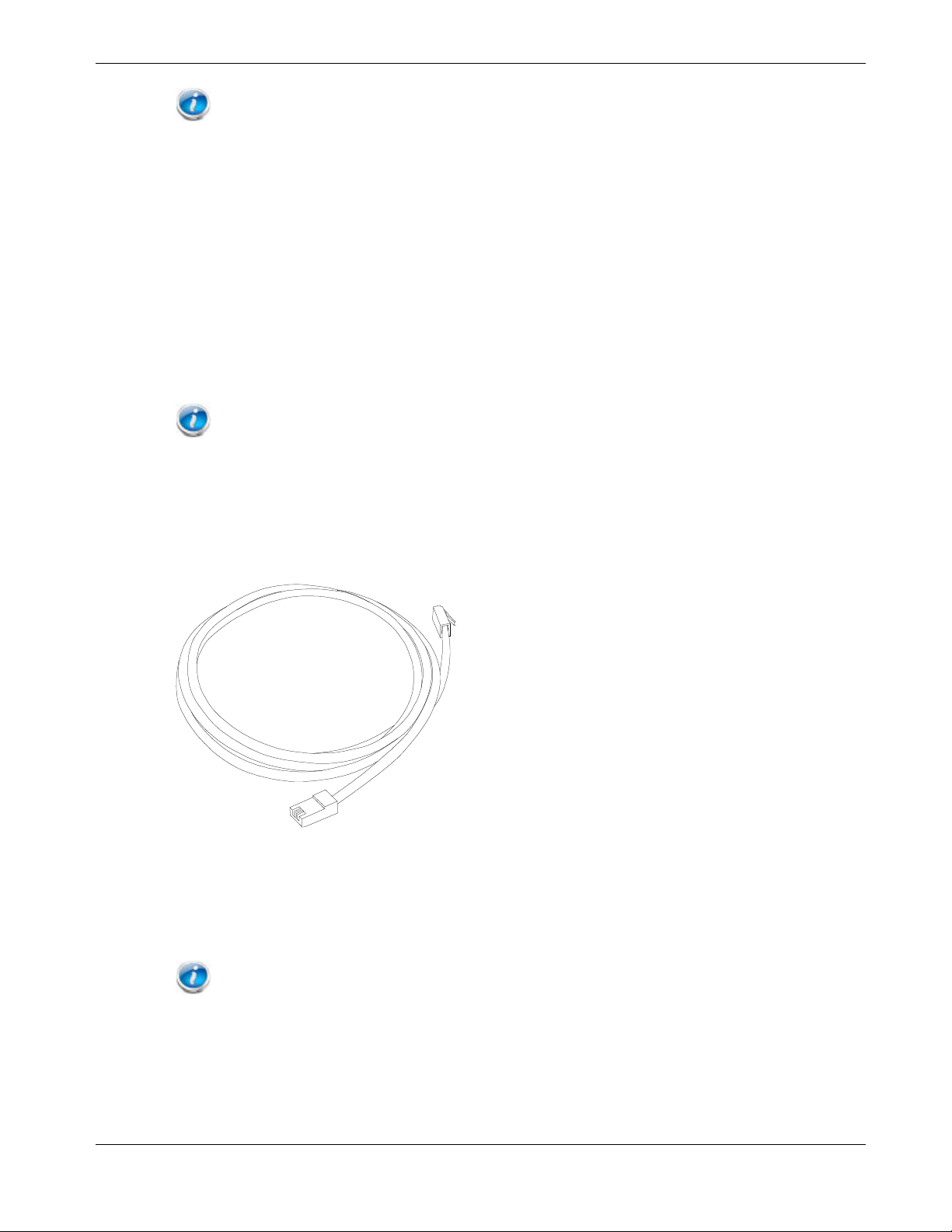
Ethernet Cable: In addition to the Ethernet cable provided, you may need an
additional Ethernet cable if you want to connect to wired clients. This is a standard
Ethernet cable with RJ45 type connectors on both ends. You can buy Ethernet cables
from any electronics retailer and many discount stores.
Information packet: your service provider should furnish you with a packet
containing information about your service and how to set it up. Read this information
carefully and contact your service provider if you have any questions.
Release 33 STANDARD 1.5 February 2015 TR3300-AC 802.11ac Wireless Router User Guide 10
Page 11

System Requirements
The Touchstone Wireless Router operates with most computers. The following describes
requirements for each operating system; see the documentation for your system for details
on enabling and configuring networking.
To use the Wireless Router, you need high-speed Internet service from your service
provider.
Recommended Hardware
The following hardware configuration is recommended. Computers not meeting this
configuration can still work with the TR3300-AC, but may not be able to make maximum
use of TR3300-AC throughput.
CPU: P4, 3GHz or faster
RAM: 1GB or greater
Ethernet: Gig-E (1000BaseT)
Wi-Fi: 802.11a, b, g, n, or ac compliant Wi-Fi equipment
Chapter 3: Product Overview
Windows
Windows XP , Windows Vista, Windows 7, or Windows 8. A supported Ethernet or
wireless LAN connection must be available.
MacOS
System 7.5 to MacOS 9.2 (Open Transport recommended) or MacOS X. A supported
Ethernet or wireless LAN connection must be available.
Linux/other Unix
Hardware drivers, TCP/IP, and DHCP must be enabled in the kernel. A supported
Ethernet or wireless LAN connection must be available.
About this Manual
This manual covers the Touchstone TR3300-AC Wireless Router. The model number is on
the label affixed to the bottom of the Wireless Router.
1. Model number
Release 33 STANDARD 1.5 February 2015 TR3300-AC 802.11ac Wireless Router User Guide 11
Page 12

2. WLAN-24 MAC address
3. PreShared Key
4. WPS PIN
What About Security?
Having a high-speed, always-on connection to the Internet requires a certain amount of
responsibility to other Internet users—including the need to maintain a reasonably secure
system. While no system is 100% secure, you can use the following tips to enhance the
system’s security:
Keep the operating system of the computer updated with the latest security patches.
Run the system update utility at least weekly.
Keep the email program updated with the latest security patches. In addition, avoid
opening email containing attachments, or opening files sent through chat rooms,
whenever possible.
Install a virus checker and keep it updated.
Chapter 3: Product Overview
Avoid providing web or file-sharing services over the Wireless Router. Besides certain
vulnerability problems, most service providers prohibit running servers on consumerlevel accounts and may suspend your account for violating the terms of service.
Use the service provider's mail servers for sending email.
Avoid using proxy software unless you are certain that it is not open for abuse by other
Internet users (some are shipped open by default). Criminals can take advantage of
open proxies to hide their identity when breaking into other computers or sending
spam. If you have an open proxy, your service provider may suspend your account to
protect the rest of the network.
The TR3300-AC ships with wireless LAN security set by default (for the same reasons
that you should run only secured proxies). See the security label on the product for the
factory security settings. If you need to modify the default wireless security settings, see
Configuring the Wireless Connection (page 18).
Release 33 STANDARD 1.5 February 2015 TR3300-AC 802.11ac Wireless Router User Guide 12
Page 13

Installing the Wireless Router
Before you start, make sure that:
You have all the Items You Need (page 10):
The modem and power outlets are available nearby.
Front Panel
The front of the Wireless Router has the following indicators:
Chapter 4
1. Power: indicates whether AC power is available to the unit.
2. WAN: indicates the status of Internet service connectivity.
3. 2.4G: indicates the status of the 2.4 GHz wireless LAN.
4. 5G: indicates the status of the 5 GHz wireless LAN.
5. LAN (1 - 4): indicates the status of LAN connectivity on each of the wired ports.
Release 33 STANDARD 1.5 February 2015 TR3300-AC 802.11ac Wireless Router User Guide 13
Page 14

6. USB: indicates whether a USB device is attached.
7. WPS: indicates Wireless Protected Setup (WPS) is active.
Indicator Lights for the TR3300-AC
The Wireless Router has several LED indicator lights to assist in troubleshooting.
LED Color/Behavior Description
Power Solid green System power is on.
WAN Solid green An IP address has been received and is ready to transmit
Flashing green The Ethernet cable connection has been detected.
Off No Ethernet cable is connected to the Wireless Router.
2.4G Wi-Fi Solid green The wireless port has linked with a wireless client.
Off Wireless is disabled.
Chapter 4: Installing the Wireless Router
data, or bridge mode is active.
5G Wi-Fi Solid green The wireless port has linked with a wireless client.
Off Wireless is disabled.
WPS Solid green WPS has been started.
Flashing green (slow
flash)
Flashing green (quick
flash)
LAN 1 – 4 Solid green 10/100/1000Mbps link detected.
Flashing green Receiving/transmitting data at 10/100/1000Mbps.
Off No Ethernet connection.
USB Solid green USB device successfully connected and active.
Flashing green USB device read/write activity.
Off No USB device connected, or the attached USB device can
WPS has been started, and Wireless Router is ready to
accept a client connection.
WPS error.
now be safely removed.
Release 33 STANDARD 1.5 February 2015 TR3300-AC 802.11ac Wireless Router User Guide 14
Page 15

Rear Panel
The rear of the Wireless Router has the following connectors and controls:
Chapter 4: Installing the Wireless Router
1. Reset button: resets the Wireless Router as if you power cycled the unit. Use a
pointed non-metallic object to press this button.
Note: If you hold the Reset button for more than five seconds, the Wireless Router will be
reset to the factory default settings and will reboot.
2. WPS Button: begins associating the Wireless Router with a wireless device.
3. USB: USB host connector - future support for external USB devices.
4. Ethernet (1 - 4): connectors for use with a computer LAN port.
5. WAN: connector for the modem.
6. Power: connector for the power cord.
Selecting an Installation Location
There are a number of factors to consider when choosing a location to install the Wireless
Router:
Release 33 STANDARD 1.5 February 2015 TR3300-AC 802.11ac Wireless Router User Guide 15
Page 16

Is an AC outlet available nearby? For best results, the outlet should not be switched and
should be close enough to the Wireless Router that extension cords are not required.
Is the modem nearby? Can you easily run cables between the Wireless Router’s location
and the modem?
If you are connecting devices to the Ethernet ports, can you easily run cables between
the Wireless Router’s location and those devices?
If you want to install the Wireless Router on a desktop, is there enough space on either
side to keep the vents clear? Blocking the vents may cause overheating.
How close are the wireless devices? In general, the Wireless Router should be located
close to the center of the user sphere. The Wireless Router wireless connection range is
typically 100–200 feet (30m–65m) for 2.4 GHz signals and less for 5 GHz signals. A
number of factors can affect connection range, as described below.
Desktop Mounting Instructions
Position the Wireless Router so that:
air flows freely around it
Chapter 4: Installing the Wireless Router
the back faces the nearest wall
it will not fall to the floor if bumped or moved
the sides of the unit are not blocked.
Note: Clean the Wireless Router using only a clean, slightly moistened, cloth. Do not use
aerosols in the vicinity of the Wireless Router.
Factors Affecting Wireless Range
A number of factors can affect the usable range for wireless connections.
Increases range
Decreases range
Locating the unit centrally
Creating as much "line-of-sight" as possible with client devices
Metal or concrete walls between the Wireless Router and other
devices
Large metal appliances, aquariums, or metal cabinets between the
Wireless Router and other devices
Interference and RF noise (2.4 GHz wireless phones, microwave
ovens, wireless speaker/receiver systems, or other wireless
networks)
Placing the device in a cabinet or other enclosed space
Note: Decreasing the range of the wireless network may be beneficial, as long as the
decreased range is sufficient for your needs. By limiting the network’s range, you reduce
interference with other networks and make it harder for unwanted users to find and connect to the
network.
Release 33 STANDARD 1.5 February 2015 TR3300-AC 802.11ac Wireless Router User Guide 16
Page 17
Note: Setting the transmit power level to High increases the range. Setting it to Medium or
Low decreases the range proportionately. Medium or Low may be more appropriate for highdensity residential locations.
Ethernet or Wireless?
There are two ways to connect the computer (or other equipment) to the Wireless Router.
The following will help you decide which is best for you:
Ethernet
Ethernet is a standard method of connecting two or more computers into a Local Area
Network (LAN). You can use the Ethernet connection if the computer has built-in Ethernet
hardware. The TR3300-AC provides support for up to four such connected devices.
Note: To connect more than four computers to the TR3300-AC through the Ethernet ports,
you need an Ethernet switch (available at computer retailers).
The Wireless Router package comes with one 4-foot (1.2m) Ethernet cable (the connectors
look like wide telephone connectors); you can purchase more cables if necessary at a
computer retailer. If you are connecting the Wireless Router directly to a computer, or to
an Ethernet switch with a cross-over switch, ask for Category 5e (CAT5e) straight-through
cable. CAT5e cable is required for gigabit Ethernet (Gig-E), not regular CAT5 cable.
Chapter 4: Installing the Wireless Router
Wireless
Wireless access lets you connect additional (wireless-capable) devices to the Wireless
Router. The 802.11 wireless LAN standard allows one or more computers to access the
TR3300-AC using a wireless (radio) signal. These connections are in addition to the
connections supported via Ethernet.
Note: You can use the wireless connection if the computer has a built-in or aftermarket
plug-in wireless adapter. To learn more about which wireless hardware works best with the
computer, see your computer dealer.
Both
If you have two or more computers, you can use Ethernet for up to four devices and
wireless for the others. To connect five or more computers to the Ethernet ports, you will
need an Ethernet switch (available at computer retailers.)
Release 33 STANDARD 1.5 February 2015 TR3300-AC 802.11ac Wireless Router User Guide 17
Page 18

Connecting the Wireless Router
1. Unplug the power to turn off the modem.
2. Connect one end of the Ethernet cable (included) to the modem, and the other end to
the WAN port on the Wireless Router.
3. Reconnect the plug on the modem to turn the modem back on. Wait approximately 2
minutes to allow the modem to fully power up.
4. Connect the power adapter (included) to the power connector on the back of the
Wireless Router, and then connect the power adapter to an available AC outlet. Wait
until the 2.4G and 5G LEDs on the front panel of the Wireless Router turn solid green.
5. To manage the setup of the Wireless Router, you can use a second Ethernet cable (not
provided) to connect a computer to an available LAN port on the TR3300-AC, or you
can connect wirelessly by using the preset wireless security settings printed on the
security label located on the bottom of the Wireless Router.
6. Open a browser on the computer to access the management interface of the Wireless
Router. If the webpage does not display correctly, try another browser. See Accessing
the Configuration Interface (page 19) for more information.
Chapter 4: Installing the Wireless Router
Note: In some cases, the service provider may redirect the browser to their welcome page so
that you can establish new service. This step may be required before you can manage the TR3300AC configuration settings.
Configuring the Wireless Connection
The TR3300-AC ships with a secure SSID that is unique for every device. Wi-Fi network
information is located on the label on the bottom of the Wireless Router. You should
configure the Wireless Router's wireless settings.
Note: At a minimum, you should set a login password and set up wireless
security. Refer to Configuring the Wireless Network (page 20) for complete instructions on
configuring the wireless connection.
Release 33 STANDARD 1.5 February 2015 TR3300-AC 802.11ac Wireless Router User Guide 18
Page 19

Basic Configuration
The Wireless Router ships with a basic factory default configuration that should allow you
to immediately access the Internet after installing the hardware according to the User’s
Guide.
If you need to modify the Wireless Router's default basic settings, or if you want to
configure advanced settings, refer to the appropriate instructions in this document.
As a minimum, it is recommended that you:
Change the default login password
Change the default wireless network name, also called the Service Set Identifier (SSID)
Wireless LAN Default Security Setting: The Wireless Router ships with
wireless LAN security set by default. See the security label on the product for
the factory security settings: network name (SSID), encryption method,
network key, and WPS PIN.
If you need to modify the Wireless Router’s default wireless security settings, or if you want
to configure any other settings, refer to the appropriate instructions in this document.
Chapter 5
Note: You must set up the computer and other client devices to work with the security
settings on the Wireless Router. Refer to the documentation for the client device for instructions on
setting security. If the computer or client device supports Wi-Fi Alliance WPS (Wireless Protected
Setup), activate WPS on the computer or client device and the Wireless Router simultaneously to
easily set up the system security.
Accessing the Configuration Interface
Perform the following steps to access the configuration interface.
1. If security has been properly set up on the computer to access the wireless LAN on the
Wireless Router, use the connection utility for the operating system to connect to the
wireless LAN using its network name (SSID), as shown on the security label.
Note: If you cannot access the wireless LAN, you must first establish a wired Ethernet
connection between the computer and the Wireless Router.
2. In the web browser, open the page http://192.168.1.1/ to access the Wireless Router
setup.
The Login screen displays.
3. Enter the user name and password and click Apply to log in.
Note: The default user name is "admin". The default password is "password", in lower case
letters.
Release 33 STANDARD 1.5 February 2015 TR3300-AC 802.11ac Wireless Router User Guide 19
Page 20

The Basic Wireless Settings screen displays.
4. Set basic setup configuration parameters as required for the system.
Note: Most configuration parameters that you may want to set can be accessed on the Basic
Wireless Settings screen or on the LAN Setup or Wireless tabs.
Configuring the Wireless Network
Perform the following procedures to make the basic configuration settings for the wireless
network.
Enabling or Disabling the Wireless Network.
Perform the following steps to enable the wireless network.
1. Access and log into the configuration interface.
2. Click the Basic Setup tab.
Chapter 5: Basic Configuration
3. Click the Enable Wireless checkbox in either the Wireless 2.4 GHz section or the
Wireless 5 GHz section to enable wireless networking for that frequency.
4. Click Apply.
Changing the Login Password
You should change the login password to something other than the default password.
Note: The default user name is "admin," the default password is "password" (both lower
case).
Perform the following steps to change the password.
1. Access and log into the configuration interface via a direct wired Ethernet or wireless
connection.
2. Click the Utilities tab.
3. Click System Settings in the side menu.
4. Enter the old password in the Current Password field.
5. Enter the new password in both the New Password and Confirm New Password
fields.
Note: Passwords are case-sensitive. Valid characters are the numbers 0 to 9, the letters a
through z and A through Z, and printable special characters (such as $, !, ?, &, #, @, and others.)
6. Click Apply.
7. Record the new passwords here:
2.4 GHz Password: ___________________________________
Release 33 STANDARD 1.5 February 2015 TR3300-AC 802.11ac Wireless Router User Guide 20
Page 21

5 GHz Password: _____________________________________
Changing the Default Wireless Network Name (SSID)
Perform the following steps to change the wireless 2.4 GHz and/or wireless 5 GHz network
name.
1. Access and log into the configuration interface.
2. Click the Basic Setup tab.
3. Enter a unique user friendly name to identify the wireless network in the Wireless
Network Name (SSID) field under either Wireless 2.4 GHz or Wireless 5 GHz.
Note: This name is also referred to as the Service Set Identifier (SSID). The name can be up
to 32 characters long. Do not duplicate any other SSID names that may be operating in the area.
4. Click Apply at the bottom of the screen.
5. Record the new network names here:
2.4 GHz Network name (SSID): ______________________________
Chapter 5: Basic Configuration
5 GHz Network name (SSID): ________________________________
Configuring Wi-Fi Protected Setup (WPS)
WPS is a standard method for easily configuring a secure connection between the Wireless
Router and computers or other wireless devices (known as enrollees) that support WPS.
When WPS is enabled you can attach other wireless devices by pressing the WPS buttons
on the device (if equipped) and on the Wireless Router, or by entering the enrollee’s PIN
and then clicking the Start WPS Association icon.
Perform the following steps to enable the wireless network.
1. Access and log into the configuration interface.
2. Click the Basic Setup tab.
3. Click WPS Settings in the side menu.
4. Click the Wi-Fi Protected Setup (WPS) Enable checkbox and click Apply to
enable WPS on the system.
5. a) If the client device has a WPS button, press the WPS buttons on the client device
and on the Wireless Router simultaneously to start the WPS association.
b) If the client device has a PIN number, enter the enrollee’s PIN in the Enrollee PIN
Code field, and then click the Start WPS Association icon. Enter the Wireless
Router’s PIN code in the Device PIN Code field if requested during connection.
6. If the connection is successful, the WPS indicator light on the Wireless Router stops
flashing and remains lit. If unsuccessful, the WPS light continues to flash for up to two
minutes (indicating that it’s ready to accept a client connection) and then turns off. If
the WPS light turns off, start the association process over.
Release 33 STANDARD 1.5 February 2015 TR3300-AC 802.11ac Wireless Router User Guide 21
Page 22

Setting Up the WAN Connection
A Dynamic or DHCP (Dynamic Host Configuration Protocol) connection is the most
commonly used WAN connection type.
Note: Do not change this setting unless your Internet Service Provider tells you to use
another connection type.
Perform the following steps to change the connection type.
1. Access and log into the configuration interface.
2. Click the WAN Setup tab.
3. Click Dynamic, Static, Dynamic (IPV6),or Static (IPV6) in the side menu to
display the appropriate screen for configuring that type of WAN connection.
4. Set the required configuration parameters for the connection type you selected as
provided by your service provider.
Note: Refer to WAN Setup in Wireless Router Configuration Screen Descriptions (page 29)
for specific instructions on setting the various connection type configuration parameters.
Chapter 5: Basic Configuration
5. Click Apply at the bottom of the screen.
Release 33 STANDARD 1.5 February 2015 TR3300-AC 802.11ac Wireless Router User Guide 22
Page 23

Advanced Configuration Options
This section explains how to use the most common advanced configuration options for the
Wireless Router in the following areas:
LAN Setup
Wireless Setup
Firewall
Utilities
Note: Refer to Wireless Router Configuration Screen Descriptions (page 29) for additional
advanced configuration options.
LAN Setup – Configuring DHCP
Chapter 6
DHCP (Dynamic Host Protocol Configuration) is enabled by default on the Wireless
Router which allows the Wireless Router to act as a DHCP server and automatically assign
an IP address to each device on the network.
DHCP is a set of rules used by devices such as a computer, Wireless Router, or network
adapter to allow the device to request and obtain an IP address from a server which
maintains a list of addresses available for use. The DHCP server ensures that all IP
addresses are unique, e.g., no IP address is assigned to a second device while the first
device's assignment is valid (its lease has not expired).
Without DHCP, the IP addresses must be entered manually at each computer or device and
a new IP address must be entered each time it moves to a new location on the network.
Perform the following steps to configure DHCP.
1. Access and log into the configuration interface.
2. Click the LAN Setup tab.
3. Click LAN Settings or LAN Settings (IPV6) in the side menu to display the LAN
Settings screen.
4. Click the Enable DHCP Server or Enable DHCP Server (IPV6) checkbox under
DHCP Server Settings.
5. Enter the Start IP Address and End IP Address for the range of IP addresses that the
DHCP Server will be allowed to assign to a network device.
6. Enter the Lease Time in seconds before the assigned IP address will expire. (After the
lease time is up, the user is automatically assigned a new dynamic IP address.)
Note: Refer to LAN Setup (page 35) for specific instructions on setting the various DHCP
configuration parameters.
Release 33 STANDARD 1.5 February 2015 TR3300-AC 802.11ac Wireless Router User Guide 23
Page 24

7. Click Apply at the bottom of the screen.
LAN Setup – Adding and Deleting DHCP Clients
The Client List screen shows the host name, IP address, and MAC address of each
computer that is connected to the network. If a computer does not have a specified host
name, then the host name field will be blank.
Perform the following steps to configure the DHCP Clients.
1. Access and log into the configuration interface.
2. Click the LAN Setup tab.
3. Click Client List in the side menu to display the Client List screen.
4. Click Add to add a reserved IP client. Select an existing DHCP client and then click
Delete to delete the client. Click Refresh to update the Clients List.
LAN Setup – Selecting the NAT Mode
NAT (Network Address Translation) allows the Wireless Router to manipulate IP
addresses so that just one single IP address can represent an entire group of computers on
the network and let them all communicate with the Internet. This conserves IP addresses
and is necessary since there are a limited number of available IP addresses for use.
Chapter 6: Advanced Configuration Options
Perform the following steps to select the NAT Mode.
1. Access and log into the configuration interface.
2. Click the LAN Setup tab.
3. Click LAN Settings in the side menu to display the LAN Settings screen.
4. Select the NAT Mode from the NAT Mode field drop-down list. The optional modes
are:
Bridged - Data will pass through the device directly without any routing.
Routed with NAT - Data will be routed by the device and all the outgoing packets will
be NATed.
Routed without NAT - Data will be routed by the device but all the outgoing packets
will not be NATed.
5. Click Apply at the bottom of the screen.
Note: A dialog box prompts you to restart the Wireless Router. Click OK to restart.
Wireless Setup – Setting the Wireless Mode
You can set the wireless mode to optimize performance based on the type of network
adapters being used by the network devices, e.g., 802.11b, 820.11g, and 802.11n. Select the
proper mode to support all of the wireless devices that will connect to the Wireless Router.
Release 33 STANDARD 1.5 February 2015 TR3300-AC 802.11ac Wireless Router User Guide 24
Page 25

Chapter 6: Advanced Configuration Options
Perform the following steps to set the wireless mode.
1. Access and log into the configuration interface.
2. Click the Wireless tab.
3. Click Basic Setup in the side menu to display the Advanced Settings screen.
4. Under Wireless 2.4 GHz or Wireless 5 GHz, select the proper mode from the Wireless
Mode drop-down list.
2.4 GHz Options: B only, G only, B/G mixed, and G/N mixed.
5 GHz Options: A only, A/N mixed, and A/N/AC mixed.
5. Click Apply at the bottom of the screen.
Note: Refer to Advanced (page 42) for instructions on setting additional advanced wireless
configuration parameters.
Note: If you have both A and B running in your network, then throughput on the entire
wireless network will be reduced.
Firewall – General Firewall Configuration Settings
The Wireless Router is equipped with a firewall that will protect the network from a wide
array of common Denial of Service (DoS) attacks, including Ping of Death (PoD) attacks.
You can disable the firewall function if needed. Turning off the firewall protection will not
leave the network completely vulnerable to hacker attacks, but it is recommended that you
enable the firewall whenever possible.
Perform the following steps to enable the firewall and make general firewall settings.
1. Access and log into the configuration interface.
2. Click the Firewall tab.
3. Click Firewall Settings in the side menu to display the Firewall Settings screen.
4. Check the Enable Firewall checkbox to enable the firewall on the network.
5. Click Apply at the bottom of the screen.
6. Click WAN Ping Blocking in the side menu to display the WAN Ping Blocking
screen.
7. Check the Block ICMP Ping Enable checkbox to protect against PoD attacks.
8. Click Apply at the bottom of the screen.
Firewall – Configuring a Virtual Server (Port Forwarding)
The port forwarding function forwards inbound traffic from the Internet to a specified
single device on the network. Examples include allowing access to a web server on the
Release 33 STANDARD 1.5 February 2015 TR3300-AC 802.11ac Wireless Router User Guide 25
Page 26

Chapter 6: Advanced Configuration Options
network, peer-to-peer file sharing, applications that allow remote access to the computer,
some gaming and videoconferencing applications, and others.
If you have a server in the network that you want to make available to the general Internet,
you can configure a virtual server. The firewall passes requests from the Internet to the
designated computer on the network. This function works by allowing you to route
external (Internet) calls for services such as a web server (port 80), FTP server (Port 21), or
other applications through the Wireless Router to the internal network.
Perform the following steps to configure a virtual server.
1. Access and log into the configuration interface.
2. Click the Firewall tab.
3. Click Virtual Servers in the side menu to display the Virtual Server Configuration
screen.
4. Select the type of server that you want to add from the Service List drop-down box.
5. Click Add to add that virtual server.
6. If necessary, adjust the following parameters for the server that you are adding.
Enable – Enable this virtual server
Description – Enter a name for the virtual server.
Inbound Port – Enter the inbound port range for the virtual server. It should be the
same range as the local port.
Type – Sets the format for the port. Options are TCP, UDP, or BOTH.
Private IP Address – Enter the IP address of the machine on the LAN that you want
the connections to go to.
Private Port – Enter the private port range for the virtual server. It should be the
same range as the inbound port.
7. Click Apply to save your settings.
Note: To delete a virtual server, first select a virtual server in the list and then click Delete.
Firewall – Configuring DMZ for Gaming or Conferencing Applications
The DMZ feature allows you to specify one computer on the network to be placed outside
of the NAT firewall. This may be necessary if the NAT feature is causing problems with an
application such as a game or video conferencing application.
Use this feature only on a temporary basis. The computer in the DMZ is not protected from
hacker attacks.
Perform the following steps to put a computer in the DMZ.
1. Access and log into the configuration interface.
2. Click the Firewall tab.
Release 33 STANDARD 1.5 February 2015 TR3300-AC 802.11ac Wireless Router User Guide 26
Page 27

3. Click DMZ in the side menu to display the DMZ Settings screen.
4. Enter the following parameters.
Enable – Click this checkbox to enable DMZ on the network.
Static IP – Displays the static IP address.
Private IP – Enter the IP address of the computer to be placed in the DMZ. Be sure
that the address is not in the range of addresses delivered by the DHCP server if
enabled. After placing the computer in the DMZ, all ports on the computer are open to
the Internet and not protected.
5. Click Apply at the bottom of the screen.
Note: To remove the computer from the DMZ, delete the entries and uncheck the Enable
DMZ checkbox.
Utilities – Viewing Network System Information
You can view status and system information for the network on the System Information
screen.
Chapter 6: Advanced Configuration Options
Perform the following steps to view system status information.
1. Access and log into the configuration interface.
2. Click the Utilities tab.
3. Click System Information in the side menu to display the System Information
screen.
Note: Refer to System Information (page 51) for an explanation of the various status
information parameters.
Utilities – Restarting the Wireless Router
It may be necessary to restart (reboot) the Wireless Router if it begins working improperly.
Restarting the Wireless Router will not delete any of the configuration settings.
Perform the following steps to restart the Wireless Router.
1. Access and log into the configuration interface.
2. Click the Utilities tab.
3. Click Restart Router in the side menu to display the Restart Router screen.
4. Click the Restart Router button to restart the Wireless Router.
Release 33 STANDARD 1.5 February 2015 TR3300-AC 802.11ac Wireless Router User Guide 27
Page 28

Utilities – Reverting to Factory Default Settings
This function restores all of the Wireless Router’s configuration settings to the factory
default setting. Perform the following steps to revert to factory default settings.
1. Access and log into the configuration interface.
2. Click the Utilities tab.
3. Click Factory Default in the side menu to display the Factory Defaults screen.
4. Click the Factory Defaults button to reset the Wireless Router to factory default
settings.
Utilities – Viewing the System Logs
The System Logs screen displays the system logs.
Perform the following steps to configure the system logs.
1. Access and log into the configuration interface.
2. Click the Utilities tab.
Chapter 6: Advanced Configuration Options
3. Click System Log in the side menu to display the System Logs.
When viewing the logs, click Refresh to update the list.
Utilities – DDNS
DDNS (Dynamic DNS) allows you to provide Internet users with a fixed domain name
(instead of an IP address which may periodically change). This allows various locations on
the Internet to access the gateway and the applications that are set up in the gateway's
virtual servers without knowing your current IP address.
Requirements
In order to use DDNS you must first create an account with a DDNS provider. The DDNS
provider maps your chosen domain name to your IP address.
Once the account is established, perform the following steps to enable DDNS.
1. Access and log into the configuration interface.
2. Click the Utilities tab.
3. Click DDNS in the side menu to display the DDNS configuration screen.
4. Click the DDNS Enable checkbox.
Note: Refer to DDNS (page 55) for specific instructions on setting the various DDNS
configuration parameters.
5. After setting the necessary configuration parameters, click Apply at the bottom of the
screen.
Release 33 STANDARD 1.5 February 2015 TR3300-AC 802.11ac Wireless Router User Guide 28
Page 29

Wireless Router Configuration Screen Descriptions
This section provides an overview of the ARRIS graphical user interface (GUI) Wireless
Router setup screens.
Each of the following tabs in the GUI and their individual sub-menus and configuration
parameters are explained in detail:
Basic Setup
WAN Setup
LAN Setup
Wireless
StreamBoost
Firewall
Utilities
Chapter 7
Basic Setup
Basic Wireless Settings
While the system has many configuration options, the options on this Basic Setup page are
those required by most users. Click the tabs to access the other configuration pages to set
advanced options. Hover the mouse pointer over the question mark icon next to an option
to view a description of that option. For changes to take effect, you must click Apply.
Release 33 STANDARD 1.5 February 2015 TR3300-AC 802.11ac Wireless Router User Guide 29
Page 30

Wireless 2.4 GHz/Wireless 5 GHz:
Enable Wireless – Click this checkbox to enable the wireless network on the system.
Wireless Network Name (SSID)– Enter a user friendly name to identify the wireless
network. This name is also referred to as the Service Set Identifier (SSID). The name can
be up to 32 characters long.
Password – Sets the Wi-Fi password. Use a password that will not be easy to guess.
Passwords are case-sensitive. Valid characters are the numbers 0 to 9, the letters a through
z and A through Z, and printable special characters (such as $, !, ?, &, #, @, and others).
You must click Apply to save the new password.
connection to change the password.
WPS Settings
Chapter 7: Wireless Router Configuration Screen Descriptions
Note: You must be logged into the configuration interface via a direct wired Ethernet
Wi-Fi Protected Setup (WPS) is the industry standard method to simplify the security
setup and management of Wi-Fi networks. You can now easily set up and connect to a
WPA-enabled 802.11 network with WPS-certified devices using either a Personal
Information Number (PIN) or the Push Button Configuration (PBC) method. Legacy
devices without WPS can be added to the network using the traditional manual
configuration method.
WPS Enable/Disable:
Wireless 2.4 GHz/Wireless 5 GHz – Click the frequency for which you want to enable WPS.
Release 33 STANDARD 1.5 February 2015 TR3300-AC 802.11ac Wireless Router User Guide 30
Page 31

WPS Enable – Click this checkbox to enable WPS on the system. WPS is a standard
method for easily configuring a secure connection between the Wireless Router and
computers or other wireless devices (known as enrollees) that support WPS. When WPS is
enabled, you can attach other wireless devices by pressing the WPS buttons on the device
(if equipped) and on the Wireless Router, or by entering the enrollee’s PIN and then
clicking the Start WPS Association icon.
PIN Method:
Enrollee PIN Code – If the client device has a WPS PIN number, enter it here, then click
Enroll.
Device PIN Code – Enter this code on the computer if requested during connection.
PBC Method:
Start PBC – Click to start the PBC connection process.
WAN Setup
Dynamic
Chapter 7: Wireless Router Configuration Screen Descriptions
A dynamic connection type is the most common type of connection. The Wireless Router
gets its IP address from a DHCP server at the service provider. If you are not sure of the
connection type, use this type. For changes to take effect, you must click Apply.
DHCP:
Enable DHCP – Click this checkbox to enable a DHCP connection for the system.
Host name – This field displays the host name of the Wireless Router.
Release 33 STANDARD 1.5 February 2015 TR3300-AC 802.11ac Wireless Router User Guide 31
Page 32

Static
Chapter 7: Wireless Router Configuration Screen Descriptions
A static IP address connection type is less common than others and uses a permanent IP
address to connect to the Internet. If your service provider gives you an IP address that
never changes, then use this option. For changes to take effect, you must click Apply.
DNS
Static IP Settings:
Enable Static IP – Click this checkbox to enable a static IP address connection for the
system.
IP Address – Enter the IP address assigned by your service provider or static IP operation.
Subnet Mask – Enter the subnet mask assigned for the device by your service provider or
static IP operation.
Gateway Address – Enter the gateway address assigned for the device by your service
provider or static IP operation.
Click here to enter your DNS Settings – If your service provider gave you specific DNS
settings, click here to go to the DNS Settings screen to enter those settings.
If your service provider gave you specific DNS settings, use this screen to enter them.
Release 33 STANDARD 1.5 February 2015 TR3300-AC 802.11ac Wireless Router User Guide 32
Page 33

DNS Settings
Automatic from ISP – Click this checkbox if the Wireless Router should automatically get
its DNS settings from your service provider.
Primary DNS Server IP – Enter the IP address of the primary DNS server.
Secondary DNS Server IP – Enter the IP address of the secondary DNS server.
Dynamic (IPV6)
Chapter 7: Wireless Router Configuration Screen Descriptions
This screen enables a DHCPv6 configured IPV6 stack. A dynamic connection type is the
most common type of connection.
The Wireless Router gets its IP address from a DHCP server at your service provider. If you
are not sure of the connection type, use this type. For changes to take effect, you must click
Apply.
Dynamic Configuration (IPV6):
Enable DHCP (IPV6) – Click this checkbox to enable a DHCP (IPV6) connection for the
system.
IP Address V6 – This field displays the IPV6 address automatically assigned by the service
provider. An IPV6 address has eight groups of four hexadecimal digits (0-9, a-f). The
groups are separated by colons (:) e.g. 2001:0db8:85a3:0000:0000:8a2e:0370:7334. A
double colon (::) is shorthand for an address of all zeros.
Delegated Prefix – This field displays the assigned IPV6 prefix to be used by addresses
allocated in the local network.
Delegated Prefix Length – This field displays the assigned IPV6 prefix length.
IPV6 Gateway Address – This field displays the gateway address.
Release 33 STANDARD 1.5 February 2015 TR3300-AC 802.11ac Wireless Router User Guide 33
Page 34

Static (IPV6)
Chapter 7: Wireless Router Configuration Screen Descriptions
This screen enables a statically configured IPV6 stack. A static IP address connection type
is less common than others and uses a permanent IP address to connect to the Internet. If
your service provider gives you an IP address that never changes, then use this option. For
changes to take effect, you must click Apply.
Static IP Settings (IPV6):
Enable Static IPV6 - Click this checkbox to enable a static IPV6 address connection for the
system.
IP Address V6– Enter the IPV6 address assigned by your service provider or static IP
operation. An IPV6 address has eight groups of four hexadecimal digits (0-9, a-f). The
groups are separated by colons (:) e.g. 2001:0db8:85a3:0000:0000:8a2e:0370:7334. A
double colon (::) is shorthand for an address of all zeros.
Prefix Length (IPV6) – The length of the network portion of this address.
IPV6 Gateway Address – Enter the gateway address assigned for the device by your service
provider or static IP operation.
Primary DNS Server (IPV6) – Enter the IPV6 address of the primary DNS server. Your
service provider will provide this information.
Secondary DNS Server (IPV6) – Enter the IPV6 address of the secondary DNS server. Your
service provider will provide this information.
Domain Name – The entry here will be displayed as the domain name on the client
devices. It can be specified by your service provider or by you.
Delegated Prefix – The network portion of the IPV6 addresses to be allocated to local
clients.
Delegated Prefix Length – The length of the network portion of the IPV6 addresses to be
allocated to local clients.
Release 33 STANDARD 1.5 February 2015 TR3300-AC 802.11ac Wireless Router User Guide 34
Page 35

LAN Setup
LAN Settings
Chapter 7: Wireless Router Configuration Screen Descriptions
You can make changes to the Local Area Network (LAN) configuration here. For changes to
take effect, you must click Apply.
Note: You can optionally set up the system so that there is more than one LAN in the
network. This is most useful for commercial applications, not home use. All of the "LAN Setup" and
"Wireless Setup" configuration parameters can be set independently for each individual LAN.
LAN IP Settings:
IP Address – This field displays the IP address of the LAN.
Subnet Mask – This field displays the subnet mask of the LAN.
DHCP Server Settings:
Enable DHCP Server – Click this checkbox to enable the use of a Dynamic Host
Configuration Protocol (DHCP) Server on the network.
Release 33 STANDARD 1.5 February 2015 TR3300-AC 802.11ac Wireless Router User Guide 35
Page 36

Chapter 7: Wireless Router Configuration Screen Descriptions
DHCP is a set of rules used by devices such as a computer, router, or network adapter to
allow the device to request and obtain an IP address from a server which maintains a list of
addresses available for use.
The DHCP server ensures that all IP addresses are unique, e.g., no IP address is assigned to
a second device while the first device's assignment is valid (its lease has not expired).
Without DHCP, the IP addresses must be entered manually at each computer in an
organization, and a new IP address must be entered each time a computer moves to a new
location on the network.
Start IP Address/End IP Address – Enter the range of IP addresses that the DHCP Server
will be allowed to assign to a network device.
Lease Time – Enter the lease time in seconds before the assigned IP address will expire.
(After the lease time is up, the user is automatically assigned a new dynamic IP address.)
A "lease" is the amount of time that a given IP address will be valid for a computer or other
network device. The lease time can vary depending on how long a user is likely to require
the Internet connection at a particular location. Using very short leases, DHCP can
dynamically reconfigure networks where there are more computers than available IP
addresses, such as educational environments.
Domain Name – This field displays the domain name.
NAT:
NAT Mode – Select the NAT Mode.
Routed with NAT - Data will be routed by the device and all the outgoing packets will
be NATed.
Routed without NAT - Data will be routed by the device but all the outgoing packets
will not be NATed.
Bridged - Data will pass through the device directly without any routing.
UPnP:
Enable UPnP – Click this checkbox to enable UPnP (Universal Plug and Play) on the
system.
Advertisement Time To Live – Enter the maximum number of hops that each UPnP packet
can be sent before it is disregarded. The default value is 4, which should be acceptable for
most home networks.
IGMP Proxy:
Enable IGMP Proxy – Click this checkbox to enable the IGMP (Internet Group
Management Protocol) proxy on the system.
Release 33 STANDARD 1.5 February 2015 TR3300-AC 802.11ac Wireless Router User Guide 36
Page 37

LAN Settings (IPV6)
Chapter 7: Wireless Router Configuration Screen Descriptions
This screen configures LAN side support for IPV6. You can make changes to the Local
Area Network (LAN) configuration here. For changes to take effect, you must click Apply.
Note: You can optionally set up the system so that there is more than one LAN in the
network. This is most useful for commercial applications not home use. All of the "LAN Setup" and
"Wireless Setup" configuration parameters can be set independently for each individual LAN.
LAN Settings (IPV6):
IP Address (IPV6) – This field displays the IPV6 address of the LAN. An IPV6 address has
eight groups of four hexadecimal digits (0-9, a-f). The groups are separated by colons (:)
e.g. 2001:0db8:85a3:0000:0000:8a2e:0370:7334. A double colon (::) is shorthand for an
address of all zeros.
Prefix Length V6 – Length of the network portion of the IPV6 address.
Link Local Address (IPV6) – IPV6 address that can be used only on this network.
DHCP Server Settings (IPV6):
Enable DHCP Server (IPV6) – Click this checkbox to enable the use of a V6 Dynamic Host
Configuration Protocol (DHCP) Server on the network.
DHCP is a set of rules used by devices such as a computer, router, or network adapter to
allow the device to request and obtain an IP address from a server which maintains a list of
addresses available for use.
The DHCP server ensures that all IP addresses are unique, e.g., no IP address is assigned to
a second device while the first device's assignment is valid (its lease has not expired).
Release 33 STANDARD 1.5 February 2015 TR3300-AC 802.11ac Wireless Router User Guide 37
Page 38

Client List
Chapter 7: Wireless Router Configuration Screen Descriptions
Without DHCP, the IP addresses must be entered manually at each computer in an
organization, and a new IP address must be entered each time a computer moves to a new
location on the network.
Start IP Address (IPV6)/End IP Address (IPV6) – Enter the range of IPV6 addresses that
the DHCP Server will be allowed to assign to a network device.
Lease Time V6 – Enter the lease time in seconds before the assigned IPV6 address will
expire. (After the lease time is up, the user is automatically assigned a new dynamic IP
address.)
A "lease" is the amount of time that a given IP address will be valid for a computer or other
network device. The lease time can vary depending on how long a user is likely to require
the Internet connection at a particular location. Using very short leases, DHCP can
dynamically reconfigure networks where there are more computers than available IP
addresses, such as educational environments.
DHCP Relay Settings (IPV6):
Enable DHCP Relay (IPV6) – Click this checkbox to enable DHCP Relay functionality on
the system.
This page shows the host name, IP address, and MAC address of each computer that is
connected to the network. If a computer does not have a specified host name, then the
host name field will be blank.
Note: You can optionally set up the system so that there is more than one LAN in the
network. This is most useful for commercial applications not home use. All of the "LAN Setup" and
"Wireless Setup" configuration parameters can be set independently for each individual LAN.
Static Client List:
Click Add to create a new fixed client lease.
Release 33 STANDARD 1.5 February 2015 TR3300-AC 802.11ac Wireless Router User Guide 38
Page 39

IP Address – Enter the client’s IP address.
Name – Enter a name for the client.
MAC Address – Enter the client’s MAC address.
Select a client and then click Delete to delete the client lease.
Attached Client List:
Click Refresh to update the client list.
Wireless
Basic Setup
Chapter 7: Wireless Router Configuration Screen Descriptions
While the system has many configuration options, the options on this Basic Setup page are
those required by most users. Click the tabs to access the other configuration pages to set
Release 33 STANDARD 1.5 February 2015 TR3300-AC 802.11ac Wireless Router User Guide 39
Page 40

Chapter 7: Wireless Router Configuration Screen Descriptions
advanced options. Hover the mouse pointer over the question mark icon next to an option
to view a description of that option. For changes to take effect, you must click Apply.
Note: You can optionally set up the system so that there is more than one LAN in the
network. This is most useful for commercial applications not home use. All of the "LAN Setup" and
"Wireless Setup" configuration parameters can be set independently for each individual LAN.
Wireless 2.4 GHz/Wireless 5 GHz:
Enable Wireless – Click this checkbox to enable the wireless network on the system.
Channel – Sets a communications channel for the Wireless Router. The default setting is
"Auto", in which the Wireless Router selects a channel with the least amount of
interference to use. For 2.4 GHz, if you manually select a channel, it’s best to choose
channel 1, 6, or 11, since these channels do not overlap. If another unit is operating in the
area, choose a channel that is farthest away from the channel that unit uses. For example,
if one is using channel 11, set yours to channel 1. For 5 GHz choose a channel that is
farthest away from the channel used by any other unit operating in the area. If you
experience interference or poor performance on a particular channel, try a different
channel.
Wireless Network Name (SSID) – Enter a user friendly name to identify the wireless
network. This name is also referred to as the Service Set Identifier (SSID). The name can
be up to 32 characters long.
Wireless Mode – Sets the wireless mode. 2.4 GHz Options are: B/G mixed, B only, G only,
and G/N mixed. 5 GHz Options are: A only, A/N mixed, and A/N/AC mixed. Select the
proper mode to support all of the wireless devices that will connect to the Wireless Router.
(802.11b supports bandwidth up to 11 Mb/s. 802.11g supports bandwidth up to 54 Mb/s.
802.11n supports bandwidth up to 300 Mb/s. 802.11ac support bandwitdh up to 1.3Gb/s.)
Channel Bandwidth – Sets the 802.11n Channel Bandwidth. Options are 20 MHz, 40MHz,
20/40 MHz, or 80MHz (5 GHz only). The default setting is 20/40 MHz.
Broadcast Network Name (SSID) – Click this checkbox to allow the SSID to be broadcast
by the Wireless Router. If enabled, the SSID could be obtained allowing unauthorized
access to the network. If you would like others not to see the access point, uncheck the
checkbox to hide the SSID.
AP Isolation – Click this checkbox to enable AP isolation. When enabled each of the
wireless clients will be in its own virtual network and will not be able to communicate with
one another. This may be useful if you have many guests using the network.
Enable WMM – Click this checkbox to enable Wi-Fi Multimedia (WMM) functionality.
Enabling WMM can help control latency and jitter when transmitting multimedia content
over a wireless connection. Disabling WMM will reduce wireless performance in 802.11n
mode.
This quality of service mechanism uses four access categories, which in order of priority
are: voice, video, best effort, and background. This ensures that applications with low
tolerance for latency and jitter are treated with higher priority than less-sensitive data
applications. WMM sets different wait times for the four categories in order to provide
priority network access for applications that are less tolerant of packet delays.
Security Mode – Sets the security mode for the Wireless Router. Can be set to
WPA/WPA2-PSK (Wi-Fi Protected Access/ Wi-Fi Protected Access 2 – Pre-Shared Key)
(most compatible); WPA2-PSK (Wi-Fi Protected Access 2 – Pre-Shared Key)
Release 33 STANDARD 1.5 February 2015 TR3300-AC 802.11ac Wireless Router User Guide 40
Page 41

(recommended); WPA2-Enterprise; or WPA/WPA2-Enterprise. 802.11n performance is
only available in WPA2.
Pre-Shared Key - Sets the WPA Pre-Shared Key. This text string is used to generate a
unique set of encryption keys for the network. Enter a text string in this field. The key can
be either ASCII (text) or Hex (hexadecimal). An ASCII text key can be from 8 to 63
characters long. Valid characters are numbers "0" through "9" and letters "a" through "z",
and printable special characters (such as $, !, ?, &, #, @, and others). A hexadecimal key
must be 64 characters long. Valid characters are numbers "0" through "9" and letters "a"
through "f".
Guest Access
Chapter 7: Wireless Router Configuration Screen Descriptions
Guest access allows access to the Internet through the WAN port, but it limits guests from
accessing the internal network, LAN, and WLAN. The feature is supported both on 2.4
GHz and 5 GHz.
Wireless 2.4 GHz/Wireless 5 GHz:
Guest SSID – Enter the SSID that you would like to assign to the guest access network. You
can configure up to three guest networks.
Guest Access Enable – Click this checkbox to enable guest access for the system.
Wireless Network Name (SSID) – Enter a user friendly name to identify the guest wireless
network. This name is also referred to as the Service Set Identifier (SSID). The name can
be up to 32 characters long.
Security mode – Sets the security mode for the Wireless Router. Available options are
WPA/WPA2-PSK or Open.
Release 33 STANDARD 1.5 February 2015 TR3300-AC 802.11ac Wireless Router User Guide 41
Page 42

Advanced
Chapter 7: Wireless Router Configuration Screen Descriptions
Pre-Shared Key – Sets the WPA Pre-Shared Key. This text string is used to generate a
unique set of encryption keys for the network. Enter a text string in this field. The key can
be either ASCII (text) or Hex (Hexadecimal). An ASCII text key can be from 8 to 63
characters long. Valid characters are numbers ‘0’ through ‘9’ and letters ‘a’ through ‘z’ as
well as most other characters. A hexadecimal key must be 64 characters long. Valid
characters are numbers ‘0’ through ‘9’ and letters ‘a’ through ‘f’.
The Advanced Settings page is used to set up the Wireless Router’s advanced wireless
functions. These settings should only be adjusted by an expert administrator since
incorrect settings can reduce wireless performance. For changes to take effect, you must
click Apply.
Wireless 2.4 GHz/Wireless 5 GHz:
Beacon Interval – Sets the time interval between beacon transmissions in milliseconds.
The Wireless Router uses these transmissions to synchronize the wireless network and its
client devices. For compliance with most client devices, the Beacon Interval should remain
set at the default of 100ms. The allowable setting range is from 20 to 1024ms.
DTIM Interval – Sets the DTIM (Delivery Traffic Indication Message) Interval. The DTIM
Interval informs the wireless client devices of the next available window for listening to
broadcast and multicast messages. When the Wireless Router sends a DTIM beacon, the
client devices hear the beacon and then listen for the messages. For compliance with most
client devices, the DTIM Interval should be left at 1 ms. The allowable setting range is
from 1 to 255 ms.
RTS Threshold – Sets the packet size limit. When the threshold is passed, the ready to
send/clear to send (RTS/CTS) function is invoked. The default setting is 2347 bytes. The
allowable setting range is from 1 to 2347 bytes.
Release 33 STANDARD 1.5 February 2015 TR3300-AC 802.11ac Wireless Router User Guide 42
Page 43

Fragment Threshold – Sets the fragmentation threshold. This threshold should be set to
equal the maximum Ethernet frame size allowable on the link including overhead. Setting
a lower threshold can damage data throughput since large frames could be fragmented
and/or collisions could occur. The default setting is 2346. The allowable setting range is
from 256 to 2346 bytes.
Guard Interval – The spacing between transmission of symbols in nanoseconds. Can be
set to short or long. Select short to provide higher throughput in networks where the
coverage distance is small (indoors). Select long to provide higher throughput in networks
where the coverage distance is large (outdoors).
StreamBoost
StreamBoost Settings
Chapter 7: Wireless Router Configuration Screen Descriptions
The StreamBoost Settings screen lets users configure the StreamBoost Quality of Service
(QoS) settings. StreamBoost is used to improve the online experience for connected clients
based on the devices they use and the applications they are running. From this screen, the
administrator can control and test the throughput limits in the downstream and upstream
directions.
StreamBoost Settings:
StreamBoost Enable – Click this checkbox to enable StreamBoost technology.
Auto Bandwidth Detection – Click this checkbox to enable Auto Bandwidth Detection.
Up Limit (Mbps) – Enter the amount of bandwidth (in megabits per second) that you want
to reserve for upstream (outgoing) traffic.
Down limit (Mbps) – Enter the amount of bandwidth (in megabits per second) that you
want to reserve for downstream (incomng) traffic.
Bandwidth Test – Click this button to run the bandwidth test.
Release 33 STANDARD 1.5 February 2015 TR3300-AC 802.11ac Wireless Router User Guide 43
Page 44

Priorities
Chapter 7: Wireless Router Configuration Screen Descriptions
Keep StreamBoost Up to Date:
Enable Automatic Update – Click this checkbox to enable automatic StreamBoost updates
during the initial 2-year manufacturer service term. The service term will begin on the date
of manufacture and run for three years or until April 1st, 2017, whichever comes first.
(After the 2-year period, the manufacturer may make further updates available via
firmware updates.) StreamBoost updates may improve the Wireless Router's Internet
traffic management capabilities through better traffic identification and bandwidth
management techniques. In exchange, the Wireless Router will provide anonymous,
performance-related information to the StreamBoost server for improved future
StreamBoost service.
The Priorities screen lets you set bandwidth priority at the connected device level to ensure
that the most important client devices have access to the bandwidth they need to perform
well. Use the Up and Down buttons to change the priority of a device in the list. Click
Apply to save your settings.
Release 33 STANDARD 1.5 February 2015 TR3300-AC 802.11ac Wireless Router User Guide 44
Page 45

STAT: Downloads
Chapter 7: Wireless Router Configuration Screen Descriptions
The Top By Downloads screen shows how bandwidth is being used in the local network on
a per-device and per-application level.
Release 33 STANDARD 1.5 February 2015 TR3300-AC 802.11ac Wireless Router User Guide 45
Page 46

STAT: Up Time
Chapter 7: Wireless Router Configuration Screen Descriptions
The Top 5 Flows by Time screen shows how bandwidth is being used in the local network
on a per-device and per-application level.
Firewall
Firewall Settings
The Wireless Router is equipped with a firewall that will protect the network from a wide
array of common hacker attacks, including Ping of Death (PoD) and Denial of Service
(DoS) attacks. You can disable the firewall function if needed. Turning off the firewall
protection will not leave the network completely vulnerable to hacker attacks, but it is
Release 33 STANDARD 1.5 February 2015 TR3300-AC 802.11ac Wireless Router User Guide 46
Page 47

recommended that you enable the firewall whenever possible. For changes to take effect,
you must click Apply.
Firewall Enable/Disable:
Enable Firewall – Click this checkbox to enable the firewall on the system.
Virtual Servers
Chapter 7: Wireless Router Configuration Screen Descriptions
The port forwarding function forwards inbound traffic from the Internet to a specified
single device on the network. Examples include allowing access to a web server on the
network, peer-to-peer file sharing, some gaming and videoconferencing applications, and
others. This function allows you to route external (Internet) calls for services such as a web
server (port 80), FTP server (Port 21), or other applications through the Wireless Router to
the internal network.
Release 33 STANDARD 1.5 February 2015 TR3300-AC 802.11ac Wireless Router User Guide 47
Page 48

Chapter 7: Wireless Router Configuration Screen Descriptions
Click Add to add a virtual server. Select a virtual server from the list and click Delete to
delete a virtual server.
Virtual Servers:
Service List – Select the kind of service you would like to set up, and click Add.
Clear Entry – To clear an entry from the Virtual Servers Table, select the entry that you
want to clear and click Clear.
Virtual Servers Table:
Description – Enter a name for the virtual server.
Inbound Port – Enter the inbound port range for the virtual server. It should be the same
range as the local port.
Type – Sets the format for the port. Options are TCP, UDP, or BOTH.
Private IP Address – Enter the IP address of the machine on the LAN that you want
the connections to go to.
Private Port – Enter the private port range for the virtual server. It should be the same
range as the inbound port.
DMZ
The DMZ feature allows you to specify one computer on the network to be placed outside
of the NAT firewall. This may be necessary if the NAT feature is causing problems with an
application such as a game or video conferencing application.
Use this feature only on a temporary basis. The computer in the DMZ is not protected
from hacker attacks.
To put a computer in the DMZ, click the Enable DMZ checkbox, enter its IP address, and
click Apply.
IP Address Of Virtual DMZ Host:
Enable DMZ – Click this checkbox to enable DMZ on the network.
Static IP – Displays the Static IP address.
Private IP – Enter the IP address of the computer to be placed in the DMZ. Be sure that
the address is not in the range of addresses delivered by the DHCP server if enabled. After
Release 33 STANDARD 1.5 February 2015 TR3300-AC 802.11ac Wireless Router User Guide 48
Page 49

placing the computer in the DMZ, all ports on the computer are open to the Internet and
not protected.
WAN Ping Blocking
You can configure the Wireless Router not to respond to an ICMP Ping (ping to the WAN
port). This offers a heightened level of security.
Block ICMP Ping:
Chapter 7: Wireless Router Configuration Screen Descriptions
Block ICMP Ping Enable – Click this checkbox to enable WAN Ping Blocking.
Remote Management
Remote management lets you make changes to the Wireless Router's settings from
anywhere on the Internet. Before you enable this function, make sure you have set the
administrator password.
Remote Management Settings:
Remote Management Enable – Click this checkbox to enable the Remote Management
feature.
Remote IP Settings – Select Any to allow management connections from any IP address, or
select IP Range to specify a range of IP addresses that can connect.
Release 33 STANDARD 1.5 February 2015 TR3300-AC 802.11ac Wireless Router User Guide 49
Page 50

ALG
Chapter 7: Wireless Router Configuration Screen Descriptions
Remote IP Address From/To – Use these fields to enter the IP addresses that can connect
to make changes to the settings. You must set Remote IP Settings to IP Range to
activate these fields.
Remote Access Port – Enter the port that you would like to use for remote access.
Application layer gateway settings allow the Wireless Router to recognize and treat certain
network protocols specially.
Application Layer Gateway:
Click the checkbox for each network protocol for which you want special handling.
Release 33 STANDARD 1.5 February 2015 TR3300-AC 802.11ac Wireless Router User Guide 50
Page 51

Utilities
System Information
Chapter 7: Wireless Router Configuration Screen Descriptions
This page shows a summary of the system’s status.
Hardware Software Version:
Serial Number – This field displays the product serial number.
Bootcode Version – This field displays the bootcode version.
Hardware Version – This field displays the hardware version.
Firmware Version – This field displays the firmware version.
Release 33 STANDARD 1.5 February 2015 TR3300-AC 802.11ac Wireless Router User Guide 51
Page 52

Chapter 7: Wireless Router Configuration Screen Descriptions
WAN Status Summary:
WAN MAC Address – This field displays the WAN MAC address.
Connection Setup – This field displays the connection type: Dynamic or Static
IP Address – This field displays the WAN IP address.
Subnet Mask – This field displays the WAN subnet mask.
Primary DNS – This field displays the Primary DNS IP address.
Secondary DNS – This field displays the Secondary DNS IP address.
Gateway – This field displays the gateway IP address.
LAN Status Summary:
MAC Address – This field displays the LAN MAC Address.
IP Address – This field displays the IP Address of the LAN.
Subnet Mask – This field displays the subnet mask of the LAN.
DHCP Server – This field displays the status of the DHCP Server: Enabled or Disabled.
Other Features Summary:
Firewall Settings - This field displays the status of the firewall settings: Enabled or
Disabled.
SSID – This field displays the status of the SSID Broadcast function: Enabled or Disabled.
Security – This field displays the status of the Security feature: Enabled or Disabled.
UPNP – This field displays the status of the UPnP feature: Enabled or Disabled.
Remote Management – This field displays the status of the Remote Management feature:
Enabled or Disabled.
WPS – This field displays the status of the WPS function: Enabled or Disabled.
Guest Access – This field displays the status of the Guest Access function: Enabled or
Disabled.
Guest SSID – This field displays the name of the guest network that you set up.
Guest Password (PSK) – This field displays the password for the guest network.
Restart Router
It may be necessary to restart (reboot) the Wireless Router if it begins working improperly.
Restarting the Wireless Router will not delete any of the configuration settings.
Release 33 STANDARD 1.5 February 2015 TR3300-AC 802.11ac Wireless Router User Guide 52
Page 53

To restart the Wireless Router, click Restart.
Click OK to restart now or click Cancel to restart later.
Factory Default
This screen lets you restore all of the Wireless Router’s configuration settings to the factory
default setting.
Chapter 7: Wireless Router Configuration Screen Descriptions
Note: A dialog box prompts you to confirm that you want to restart the Wireless Router.
Click Factory Defaults to restore the factory default configuration settings.
Note: A dialog box prompts you to confirm that you want to restore the factory default
settings. Click OK to restore now or click Cancel to restore later.
Firmware Upgrade
From time to time, ARRIS may release new versions of firmware for the Wireless Router to
provide improvements and fixes to problems that may have existed. Use the Browse
button to locate the new firmware file on a local device, and click Update to start the
update procedure.
Release 33 STANDARD 1.5 February 2015 TR3300-AC 802.11ac Wireless Router User Guide 53
Page 54

System Settings
Chapter 7: Wireless Router Configuration Screen Descriptions
This page allows you to make certain system settings. For changes to take effect, you must
click Apply.
Administrator Login:
Current Password – Enter the old password to change the administrator password.
New Password/Confirm New Password – Enter the new password in both fields to change
the administrator password.
Login Timeout – Enter the number of seconds that these web pages can remain idle before
the user is logged out.
Time And Time Zone:
Current Time – Displays the current time.
Current Language – Select the language you want to use.
Time Zone – Select the time zone.
Daylight Savings – Click this checkbox to automatically update the system clock for
Daylight Saving Time.
Primary NTP Server – The host name or IP address of the primary NTP server.
Secondary NTP Server – The host name or IP address of the secondary NTP server.
Release 33 STANDARD 1.5 February 2015 TR3300-AC 802.11ac Wireless Router User Guide 54
Page 55

System Log
Chapter 7: Wireless Router Configuration Screen Descriptions
DDNS
This page displays the system logs. Click Refresh to update the list. Click Clear Log to
clear the list.
DDNS (Dynamic DNS) allows you to provide Internet users with a fixed domain name
(instead of an IP address which may periodically change). This allows various locations on
the Internet to access the Wireless Router and the applications that are set up in the
gateway's virtual servers without knowing your current IP address. For changes to take
effect, you must click Apply.
Release 33 STANDARD 1.5 February 2015 TR3300-AC 802.11ac Wireless Router User Guide 55
Page 56

Chapter 7: Wireless Router Configuration Screen Descriptions
Note: You must first create an account with a DDNS provider in order to use DDNS. The
DDNS provider maps the chosen domain name to your IP address.
DDNS Setting:
DDNS Enable – Click this checkbox to enable DDNS on the system.
DDNS Service – Sets the DDNS provider that the account uses. The options are DynDNS
and TZO.
User Name – Enter the user name for the DDNS account.
Password – Enter the password for the DDNS account. (Provided by your DDNS
provider.)
Domain Name – Enter the domain name you selected to use with the DDNS account.
Release 33 STANDARD 1.5 February 2015 TR3300-AC 802.11ac Wireless Router User Guide 56
Page 57

Troubleshooting
The Wireless Router is plugged in, but the Power light is Off
Check all power connections. Is the power cord plugged in firmly at both ends?
If you plugged the power cord into a power strip, make sure the strip is switched on.
Avoid using an outlet controlled by a wall switch, if possible.
Finally, check the fuse or circuit breaker panel.
I'm not getting on the Internet (all connections)
It may take several minutes to establish a connection the first time you power up the
Wireless Router, especially when many people are online. Always leave the Wireless
Router plugged into AC power and connected to the modem.
Check the front panel lights:
Chapter 8
The Power and WAN lights should be on.
If the Power light blinks for more than 30 minutes, call your service provider for
assistance.
Check the cable connections. Connectors should be tight. Cables should not be pinched,
kinked, or bent sharply—any of these can cause a break or short in the cable (you may have
to replace the cable).
Proceed to the Ethernet or wireless solutions if necessary.
I'm not getting on the Internet (Ethernet)
If you are using a switch, is the switch turned on?
Are you using the right type of Ethernet cable? Use an RJ45 Cat5e cable for direct
connection to a computer; use a cross-over cable for connection to a switch.
Press the Reset button on the back of the Wireless Router.
A misconfiguration could lock out all access to the Wireless Router. If you think this has
happened, see Resetting the Wireless Router to Factory Defaults.
I'm not getting on the Internet (Wireless)
Check the indicator lights, see Using the Wireless Router — the Wi-Fi light should be on.
Does the connection utility discover your wireless LAN? If you turned off “Broadcast SSID”
you need to manually enter the name of the wireless LAN in the connection utility.
Release 33 STANDARD 1.5 February 2015 TR3300-AC 802.11ac Wireless Router User Guide 57
Page 58

Change the security mode to “disabled”. Enable one of the other security modes as soon as
you find the problem.
A misconfiguration could lock out all access to the Wireless Router. If you think this has
happened, see Resetting the Wireless Router to Factory Defaults.
My wireless Internet connection stops working sometimes
This is usually caused by interference. Two common sources are 2.4GHz “remote”
telephones and microwave ovens. If you cannot remove the interfering product, try using a
different channel.
I can get on the Internet, but everything is slow
If the Web site you are visiting is very popular, that site may be having trouble servicing all
the requests. If other sites download quickly, wait for a few minutes and try again. Usage
during peak hours may also affect the connection speed.
Other communications on the LAN, or interference with wireless connections, may slow
down the connection.
Chapter 8: Troubleshooting
Release 33 STANDARD 1.5 February 2015 TR3300-AC 802.11ac Wireless Router User Guide 58
Page 59

ARRIS Contacts
ARRIS offers broadband service providers a complete, integrated, application-oriented IP
suite of back-office automation tools for network content, subscriber, and workforce
management as well as advanced advertising and on demand services.
Before You Call ARRIS Support
When working with Technical Support, you can help us to expedite your call by following
these guidelines:
Please be prepared to give your Technical Support Contract ID number whenever you
contact ARRIS Technical Support. If you do not know your Technical Support Contract
ID number or have questions about a support contract, please contact ARRIS Technical
Services at services.orders@arrisi.com or (678) 473-8302.
Be prepared to provide your name, company name, site location, serial number of the
system you are calling about (if applicable), system and software version numbers, and
as much detail about the problem as possible.
Chapter 9
Review available documentation, including release notes, product and installation
manuals, and online help for information about your problem.
Do not reboot or restart equipment or software processes prior to consulting with
ARRIS Technical Support—vital data that could assist in resolving the problem can be
lost when these actions are performed.
All personnel who call Technical Support should have a high level of familiarity with
the ARRIS system, including knowing the system passwords. We strongly recommend
that you have personnel trained through ARRIS Educational Services programs.
ARRIS Technical Support supports ARRIS-supplied products only. Issues related to other
hardware, software, or non-ARRIS networks must be addressed by your organization or
the appropriate third-party vendor.
By Telephone
North America Region
Legacy ARRIS +1 888 221 9797 (North America)
Legacy Motorola Home + 1 888 944 4357 (North America)
+1 678 473 5656 (Worldwide)
+1 215 323 2345 (Worldwide)
Release 33 STANDARD 1.5 February 2015 TR3300-AC 802.11ac Wireless Router User Guide 59
Page 60

Latin America Region:
Argentina: Legacy Motorola Home 0 800 666 3601
Aruba: Legacy Motorola Home 215 323 2346
Bolivia: Legacy Motorola Home 800 100 694
Brazil: Legacy Motorola Home 0 800 891 5314
Legacy ARRIS +55 11 2737 7629
Chile: Legacy Motorola Home 1230 020 5564
Legacy ARRIS +56 2 678 4500
Colombia: Legacy Motorola Home 1 8005 1 80947
Legacy ARRIS +57 1 381 9103
Costa Rica: Legacy Motorola Home 215 323 2346
Ecuador: Legacy Motorola Home 215 323 2346
El Salvador: Legacy Motorola Home 800 6625
Chapter 9: ARRIS Contacts
Honduras: Legacy Motorola Home 800 0123, then 866 842 0264
Mexico: Legacy Motorola Home 001 866 391 2349
Legacy ARRIS 01 800 522 7747 or +52 55 22828531
Panama: Legacy Motorola Home 001 800 203 4345
Peru: Legacy Motorola Home 0 800 5 3651
Puerto Rico: Legacy Motorola Home 866 862 2627
Rep. Dominicana: Legacy Motorola Home 1 888 751 8898
Venezuela: Legacy Motorola Home 0 800 100 9161
Europe Region:
Europe: Legacy ARRIS +31 20 311 2525
Belgium: Legacy Motorola Home 0 800 72 163
Denmark: Legacy Motorola Home 80 88 6748
Finland: Legacy Motorola Home 0 800 114 263
France: Legacy Motorola Home 0 800 90 7038
Germany: Legacy Motorola Home 0 800 18 73019
Hungary: Legacy Motorola Home 06 800 18164
Ireland: Legacy Motorola Home 1 800 55 9871
Israel Golden Lines: Legacy Motorola Home 1 809 25 2071
Israel Bezeq: Legacy Motorola Home 1 809 42 9181
Israel Barak: Legacy Motorola Home 1 809 31 5435
Italy: Legacy Motorola Home 800 788 304
Release 33 STANDARD 1.5 February 2015 TR3300-AC 802.11ac Wireless Router User Guide 60
Page 61

Luxembourg: Legacy Motorola Home 0 800 2 5310
Chapter 9: ARRIS Contacts
Netherlands Holland:
Norway: Legacy Motorola Home 800 15 670
Poland: Legacy Motorola Home 00 800 111 3671
Portugal: Legacy Motorola Home 800 81 3461
Spain: Legacy Motorola Home 900 99 1771
Sweden: Legacy Motorola Home 020 79 0241
Switzerland: Legacy Motorola Home 0 800 561 872
United Kingdom: Legacy Motorola Home 0 800 404 8439
Legacy Motorola Home 0 800 022 0176
Asia Region:
Asia Legacy ARRIS +86 755 8634 9110
Legacy Motorola Home +1 847 725 4011 (Worldwide)
Japan Region:
Japan: Legacy ARRIS +81 3 5461 7320
Legacy Motorola Home +1 847 725 4011 (Worldwide)
Korea Region:
Korea: Legacy ARRIS +82 31 740 4203
Legacy Motorola Home +1 847 725 4011 (Worldwide)
China Region:
China: Legacy ARRIS +86 755 8634 9110 or 4008810685 (in
China only)
Legacy Motorola Home +1 847 725 4011 (Worldwide)
Australia / New Zealand Region:
Australia /
New Zealand
Legacy ARRIS +86 755 8634 9110
Legacy Motorola Home 61 3 81997220 or 1800 242664
(Australia only)
Release 33 STANDARD 1.5 February 2015 TR3300-AC 802.11ac Wireless Router User Guide 61
Page 62

By Email
Chapter 9: ARRIS Contacts
North America:
Headend and Network Equipment:
RF Optics: Ruckus, Optics, Amps, Nodes,
Transmitters, CHP, Passives,
OptiMax, CoreWave, CoreView
CMTS Products: C3, C4, ICO, ASA, CxM, CMTS1000,
CMTS1500, E6000
CMTS Product: BSR, SRM4, HSIM4, TX32, RX48,
SRM10G
Moxi and WHS
Products:
D5 and DVS
Products:
DVS Products: CAS, DACs, CASMR, APEX3000,
EMP Products: AdEdge, APS, BEQ6XXX, BME50,
Moxi, MCR, Portal, WHS, WHS5225,
MediaPlayer, Whole Home Solution,
Gateway
D5, Application Manager, VIPr,
Hemi, Encore, Quartet, Prelude, EGT
or DVS
NC2000, DreamGallery, Secure
Media, VideoFlow, AVP100, STBs,
AS-RAC, QT Plus, CherryPicker,
Encoder, Astria
BMR1200, CVEx, MSP2XXX, RMS,
SBSS, SVA, VMS
RFOptics-support@arrisi.com
techsupport.na@arrisi.com
tac.helpdesk@arrisi.com
techsupport.na@arrisi.com
techsupport.na@arrisi.com
tac.helpdesk@arrisi.com
emp-support@arrisi.com
Digital Ad Insertion: Ad Insertion, Skyvision, Spots, ACM,
n5, XMS
Video on Demand: Video OnDemand, VOD, nABLE,
CMM, n5, XMS, Transit
VOD Products: B1 Video Server, M3 Video Server,
cDVR Video Solution
WorkAssure: WorkAssure, I&R, SageQuest,
Wireless Matrix, Tech Director, Tech
Calendar, SSM Alarms
Assurance Products: ServAssure, OpsLogic, Powersense,
SALIVE, EventAssure, HouseCheck,
Data Warehouse, Starnodes
GPON Product: GPON, POL, Carrier Ethernet tac.helpdesk@arrisi.com
Satellite and
Modular Systems:
Korea: Legacy ARRIS Products techsupport.korea@arrisi.com
Korea: Legacy Motorola Home tac.helpdesk@arrisi.com
Australia / New
Zealand:
DSR, Uplink, IPTV, Encoder tac.helpdesk@arrisi.com
Legacy ARRIS Products techsupport.asia@arrisi.com
ai-support@arrisi.com
vod-support@arrisi.com
tac.helpdesk@arrisi.com
workassure-support@arrisi.com
assurance-support@arrisi.com
Release 33 STANDARD 1.5 February 2015 TR3300-AC 802.11ac Wireless Router User Guide 62
Page 63

Chapter 9: ARRIS Contacts
Australia / New
Zealand:
Legacy Motorola Home support.anz@arrisi.com
Customer Premise Equipment:
Touchstone Products: TGxxx, TMxxx, Touchstone, TTM,
Packet Ace, Cornerstone, HDT,
Incognito, CableModem, eMTA,
Telephone Gateway
CableModem: Cable Modem, MTA tac.helpdesk@arrisi.com
techsupport.na@arrisi.com
International (All Products):
Latin America: Legacy ARRIS Products techsupport.cala@arrisi.com
Latin America: Legacy Motorola Home tac.helpdesk@arrisi.com
Europe: Legacy ARRIS Products techsupport.europe@arrisi.com
Europe: Legacy Motorola Home tac.helpdesk@arrisi.com
Asia: Legacy ARRIS Products techsupport.asia@arrisi.com
Asia: Legacy Motorola Home tac.helpdesk@arrisi.com
Japan: Legacy ARRIS Products techsupport.japan@arrisi.com
Japan: Legacy Motorola Home tac.helpdesk@arrisi.com
Ask ARRIS Customer Portal
The Ask ARRIS Customer Portal enables you to:
Use innovative search technology to deliver fast, relevant, reliable information exactly
when you need it, 24x7
Manage technical support cases for your products, support level, and site location
Access technical documentation and webcasts
To use the portal, you will need to register for the site using your support contract ID and
email address. To access the customer portal:
http://www.arris.com/support
Global Knowledge Services and Training
For more information about Global Knowledge Services and the programs we offer, e-mail
us at:
training@arris.com
Release 33 STANDARD 1.5 February 2015 TR3300-AC 802.11ac Wireless Router User Guide 63
Page 64

TR3300-AC 802.11ac Wireless Router User Guide
Corporate Headquarters
ARRIS · Suwanee · Georgia · 30024 · USA
T: 1-678-473-2000 F: 1-678-473-8470
www.arris.com
 Loading...