

Page 1
Page 2

© 1999 aprilia s.p.a. - Noale (VE)
★
3!&%497!2.).'3
4%#(.)#!,
First edition: may 1999
Reprint: november 1999, march 2001
Produced and printed by:
editing division
Soave (VERONA) - Italy
Tel. +39 - 045 76 11 911
Fax +39 - 045 76 12 241
E-mail: customer@stp.it
www.stp.it
On behalf of:
aprilia s.p.a.
via G. Galilei, 1 - 30033 Noale (VE) - Italy
Tel. +39 - 041 58 29 111
Fax +39 - 041 44 10 54
www.aprilia.com
The following precautionary warnings are
used throughout this manual in order to
convey the following messages:
Safety warning. When you find this
a
symbol on the vehicle or in the
manual, be careful to the potential risk
of personal injury. Non-compliance with
the indications given in the messages
preceded by this symbol may result in
grave risks for your and other people’s
safety and for the vehicle!
aWARNING
Indicates a potential hazard which may
result in serious injury or even death.
aCAUTION
Indicates a potential hazard which may
result in minor personal injury or damage to the vehicle.
NOTE The word “NOTE” in this manual
precedes important information or instructions.
The operations preceded by this
symbol must be repeated also on
the opposite side of the vehicle.
If not expressly indicated otherwise, for the
reassembly of the units repeat the disassembly operations in reverse order.
The terms “right” and “left” are referred to
the rider seated on the vehicle in the normal riding position.
Any mention to the use of the vehicle
.
with passenger is to be intended as referred only to the countries where this is allowed.
In the text and figures the symbols
preceded by the symbol of the model
2
(
. +
indicated.
7!2.).'302%#!54)/.3
'%.%2!,!$6)#%
Before starting the engine, carefully read
this manual and in particular the section
“SAFE DRIVE”.
Your and other people’s safety depends
not only on your quickness of reflexes and
on your agility, but also on what you know
about the vehicle, on its efficiency and on
your knowledge of the basic information for
“SAFE DRIVE”. Therefore, get a thorough
knowledge of the vehicle, in such a way as
to be able to drive in the traffic safely.
) refer exclusively to the model
3 1
use and maintenance SR 50 - SR 125 - SR 150
2
Page 3
NOTE This manual must be considered
as an integral part of the vehicle and must
always accompany it, even in case of resale.
aprilia has carried out this manual with the
maximum attention, in order to supply the
user with correct and updated information.
However, since aprilia constantly improves the design of its products, there
may be slight discrepancies between the
characteristics of your vehicle and those
described in this manual.
For any clarification concerning the information contained in this manual, do not
hesitate to contact your aprilia Official
Dealer.
The user of the vehicle in these countries
must:
– contact an aprilia Official Dealer to have
the non-homologated components replaced with others homologated for use
in the country in question;
– carry out the required periodical inspec-
tions.
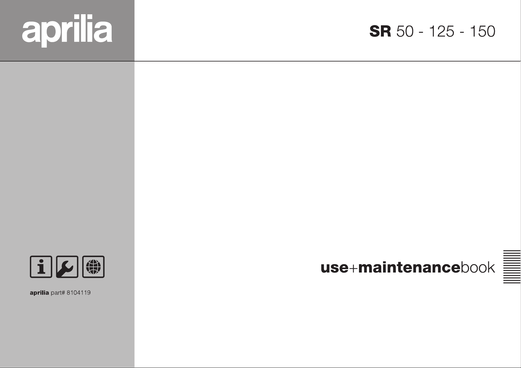
NOTE Soon after purchasing the vehi-
cle, write down the identification data indicated on the SPARE PARTS IDENTIFICATION LABEL in the table here below. The
label is stuck on the right beam of the
frame; to be able to read it, remove the
right inspection cover, see p. 55 (REMOVING THE RIGHT AND LEFT INSPECTION
COVERS).
In this manual the various versions are indicated by the following symbols:
50 cm# model
x
125 cm# model
z
150 cm# model
{
automatic light switching version
e
(Automatic Switch-on Device)
optional
m
liquid-cooled version
q
drum brake version
t
catalytic version
o
VERSION:
I
Italy
S
Singapore
For control and repair operations not expressly described in this publication, for the
purchase of aprilia genuine spare parts,
accessories and other products, as well as
for specific advice, contact exclusively
aprilia Official Dealers and Service Centers, which guarantee prompt and accurate
assistance.
Thank you for choosing aprilia. We wish
you a nice ride.
All rights as to electronic storage, reproduction and total or partial adaptation, with
any means, are reserved for all Countries.
NOTE In some countries the antipollu-
tion and noise regulations in force require
periodical inspections.
These data indicate:
– YEAR = year of manufacture (Y, 1, 2, ...);
– I.M. = modification code (A, B, C, ...);
– COUNTRY CODES = homologation
country (I, UK, A, ...).
and are to be supplied to the aprilia Offi-
cial Dealer as reference data for the purchase of spare parts or specific accessories of the model you have acquired.
United Kingdom
U
Austria
a
Portugal
p
Finland
F
Belgium
B
Germany
d
France
f
Spain
E
Greece
G
Holland
O
Switzerland
Y
Denmark
D
Japan
J
Slovenia
s
Israel
i
South Korea
¬
Malaysia
M
Chile
c
Croatia
H
Australia
A
United States
u
of America
Brazil
Ä
South Africa
R
New Zealand
n
Canada
C
use and maintenance SR 50 - SR 125 - SR 150
3
Page 4

4!",%/&#/.4%.43
SAFE DRIVE ...............................................................5
BASIC BASIC SAFETY RULES ...............................6
CLOTHING ...............................................................9
ACCESSORIES ......................................................10
LOAD ...................................................................... 10
ARRANGEMENT
OF TmHE MAIN ELEMENTS
ARRANGEMENT
OF THE MAIN ELEMENTS
ARRANGEMENT OF THE CONTROLS /
INSTRUMENTS AND INDICATORS.........................16
INSTRUMENT AND INDICATOR TABLE...............17
MAIN INDEPENDENT CONTROLS
CONTROLS ON THE LEFT SIDE
OF THE HANDLEBAR............................................18
CONTROLS ON THE RIGHT SIDE
OF THE HANDLEBAR............................................19
MAIN INDEPENDENT CONTROLS
CONTROLS ON THE LEFT SIDE
OF THE HANDLEBAR............................................20
CONTROLS ON THE RIGHT SIDE
OF THE HANDLEBAR............................................21
IGNITION SWITCH .................................................22
STEERING LOCK...................................................22
AUXILIARY EQUIPMENT .........................................23
UNLOCKING / LOCKING THE SADDLE................23
CRASH HELMET / GLOVE COMPARTMENT .......23
ANTI-THEFT HOOK ...............................................23
BATTERY / TOOL KIT COMPARTMENT...............24
BAG HOOK.............................................................24
REAR MUDGUARD EXTENSION ..........................24
..............................12
+.........................14
....................18
+............20
+ DIRECTION
INDICATOR EXTENSIONS ....................................24
MAIN COMPONENTS ...............................................25
FUEL.......................................................................25
LUBRICANTS ......................................................... 26
BRAKE FLUID - recommendations.........................27
DISC BRAKES........................................................28
REAR DRUM BRAKE .............................................29
. COOLANT 1 ................................................30
TYRES ....................................................................32
. AUTOMATIC
LIGHT SWITCHING VERSION
_ .......................33
+ AUTOMATIC
LIGHT SWITCHING VERSION
_ .......................33
CATALYTIC SILENCER
EXHAUST SILENCER ............................................34
INSTRUCTIONS FOR USE .......................................35
PRELIMINARY CHECKING OPERATIONS ...........35
STARTING ..............................................................36
DEPARTURE AND DRIVE .....................................38
2 ..................................34
. RUNNING-IN ...................................................40
+ RUNNING-IN ............................................40
STOPPING .............................................................41
PARKING ................................................................41
POSITIONING THE VEHICLE
ON THE STAND .....................................................42
SUGGESTIONS TO PREVENT THEFT .................42
MAINTENANCE ........................................................43
REGULAR SERVICE
INTERVALS CHART
REGULAR SERVICE
INTERVALS CHART
IDENTIFICATION DATA.........................................48
................................... 44-45
+............................ 46-47
. AIR CLEANER .................................................49
+ AIR CLEANER ..........................................50
CHECKING THE BRAKE PAD WEAR....................51
CHECKING THE SHOE WEAR ..............................51
CHECKING THE STEERING..................................52
CHECKING THE ENGINE FULCRUM AXIS ..........52
REMOVING
THE COVER SUPPORT ELEMENT.......................53
REMOVING THE FRONT COVER .........................53
REMOVING
THE LOWER HANDLEBAR COVER ......................54
PARTIAL REMOVAL
OF THE UPPER HANDLEBAR COVER.................54
REMOVING THE RIGHT
AND LEFT INSPECTION COVERS........................55
. INSTALLING
THE REAR MUDGUARD EXTENSION ..................56
+ REMOVING
THE NUMBER PLATE SUPPORT..........................56
+ INSTALLING
THE REAR MUDGUARD EXTENSION ..................57
+ REMOVING
THE WHOLE DIRECTION INDICATOR .................58
+ INSTALLING
THE DIRECTION INDICATOR EXTENSIONS .......58
. REMOVING THE LOWER SHIELD COVER ...59
REMOVING THE FRONT INNER SHIELD ............ 60
REMOVING THE REAR-VIEW MIRRORS ............ 61
CHECKING THE STAND ....................................... 61
CHECKING THE SWITCHES ................................ 61
. IDLING ADJUSTMENT ................................... 62
+ IDLING ADJUSTMENT ............................ 63
ADJUSTING THE ACCELERATOR CONTROL .... 63
SPARK PLUG ........................................................ 64
BATTERY............................................................... 65
LONG INACTIVITY OF THE BATTERY ................ 65
CHECKING AND CLEANING THE TERMINALS .. 66
REMOVING THE BATTERY.................................. 66
INSTALLING THE BATTERY ................................ 67
. CHECKING THE ELECTROLYTE LEVEL...... 67
. RECHARGING THE BATTERY ...................... 68
+ RECHARGING THE BATTERY ............... 68
CHANGING THE FUSES....................................... 69
ADJUSTING
THE VERTICAL HEADLIGHT BEAM..................... 70
BULBS ................................................................... 70
. CHANGING THE HEADLIGHT BULBS .......... 71
. CHANGING THE HEADLIGHT BULBS
C % K - _............................................. 71
+ CHANGING THE HEADLIGHT BULBS ... 72
CHANGING THE FRONT
DIRECTION INDICATOR BULBS .......................... 73
CHANGING THE REAR
DIRECTION INDICATOR BULBS .......................... 73
CHANGING THE DASHBOARD BULBS ............... 74
CHANGING THE REAR LIGHT BULB................... 75
CHANGING THE NUMBER PLATE BULB ............ 75
TRANSPORT............................................................ 76
DRAINING THE FUEL TANK ................................. 76
CLEANING ............................................................... 77
LONG PERIODS OF INACTIVITY ......................... 78
TECHNICAL DATA .................................................. 79
LUBRICANT CHART ...................................... 84
.
+
Importers ........................................................... 86-87
WIRING DIAGRAM - SR 50 ................................... 88
WIRING DIAGRAM - SR 50
WIRING DIAGRAM - SR 50
WIRING DIAGRAM - SR 125 - SR 150.................. 94
WIRING DIAGRAM - SR 125 - SR 150
LUBRICANT CHART ............................... 85
........... 96
J
....... 90
C % K _
............................ 92
-
use and maintenance SR 50 - SR 125 - SR 150
4
Page 5

safe drive
Page 6
"!3)#"!3)#3!&%4925,%3
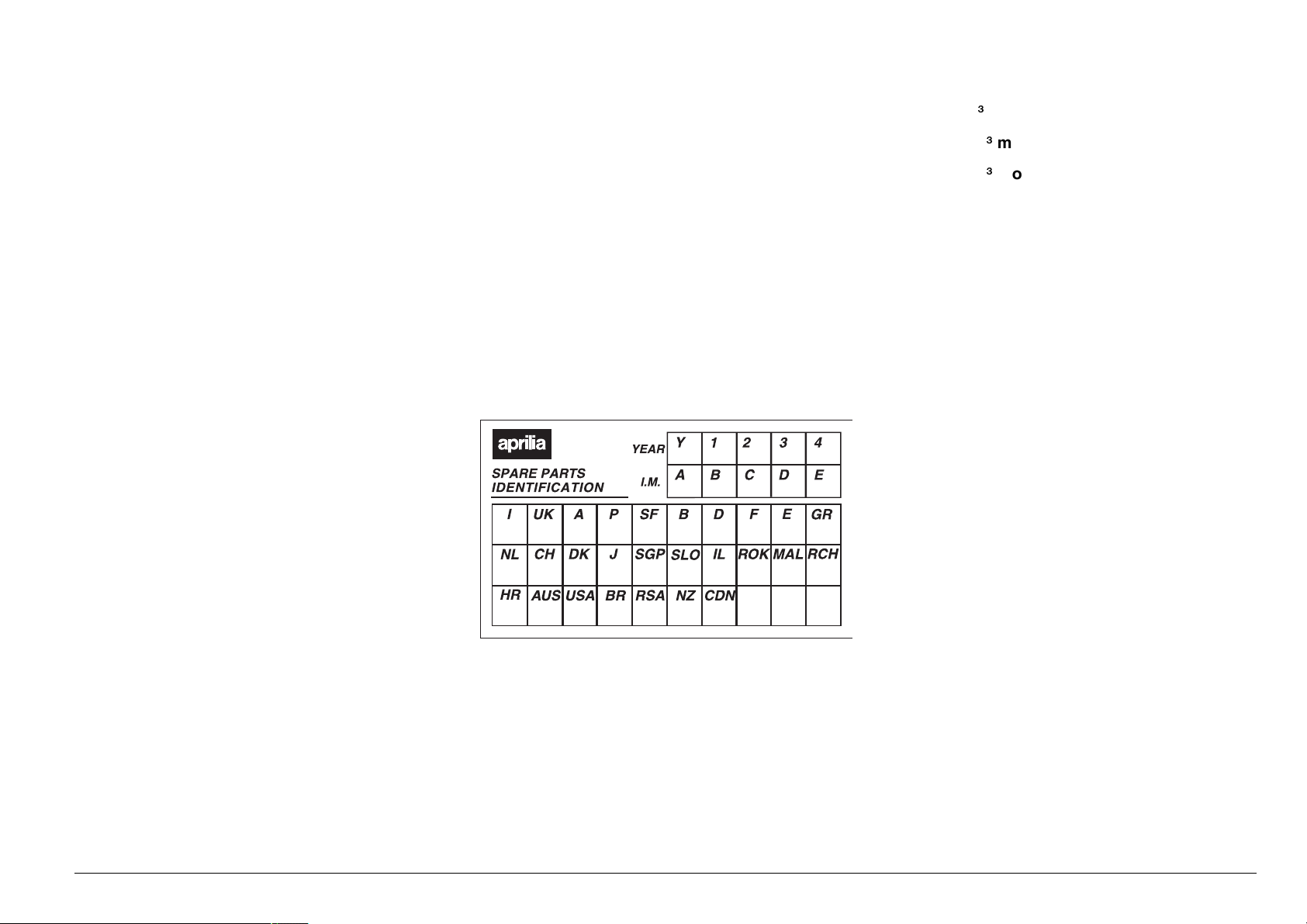
To drive the vehicle it is necessary to be in
possession of all the requirements prescribed by law (driving licence, minimum
age, psychophysical ability, insurance,
state taxes, vehicle registration, number
plate, etc.).
Gradually get to know the vehicle by driving it first in areas with low traffic and/or private areas.
The use of medicins, alcohol and drugs or
psychotropic substances notably increases
the risk of accidents.
Be sure that you are in good psychophysical conditions and fit for driving and pay
particular attention to physical weariness
and drowsiness.
Most road accidents are caused by the
driver’s lack of experience.
NEVER lend the vehicle to beginners and,
in any case, make sure that the driver has
all the requirements for driving.
use and maintenance SR 50 - SR 125 - SR 150
6
Page 7
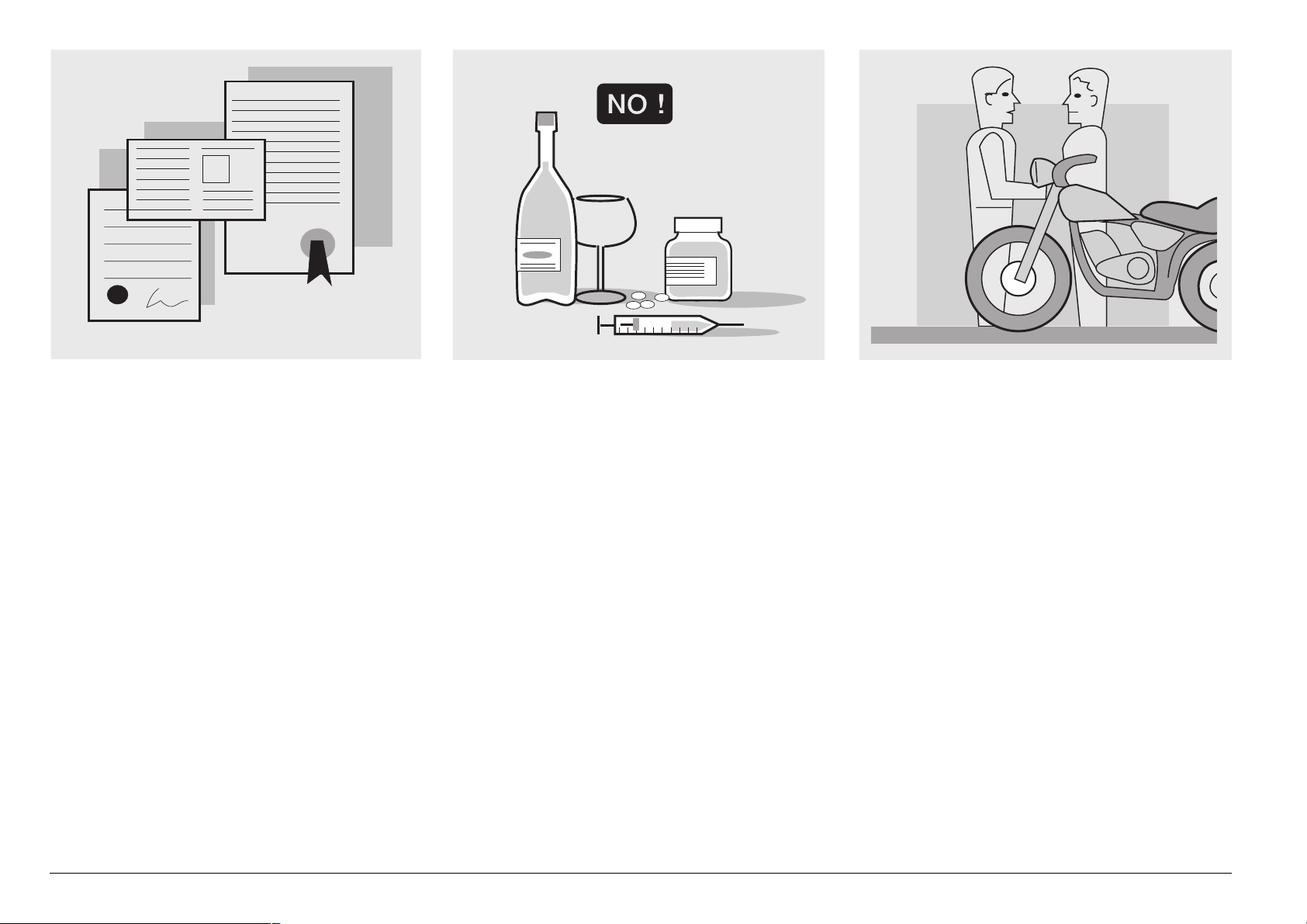
Rigorously observe all road signs and national and local road regulations.
Avoid abrupt movements that can be dangerous for yourself and other people (for
example: rearing up on the back wheel,
speeding, etc.), and give due consideration
to the road surface, visibility and other driving conditions.
Avoid obstacles that could damage the vehicle or make you lose control.
Avoid riding in the slipstream created by
preceding vehicles in order to increase
your speed.
Always keep both hands on the handlebars
and both feet on the footboard (or on the
footrests), in the correct driving posture.
Avoid standing up or stretching your limbs
while driving.
use and maintenance SR 50 - SR 125 - SR 150
7
Page 8
OIL
COOLER
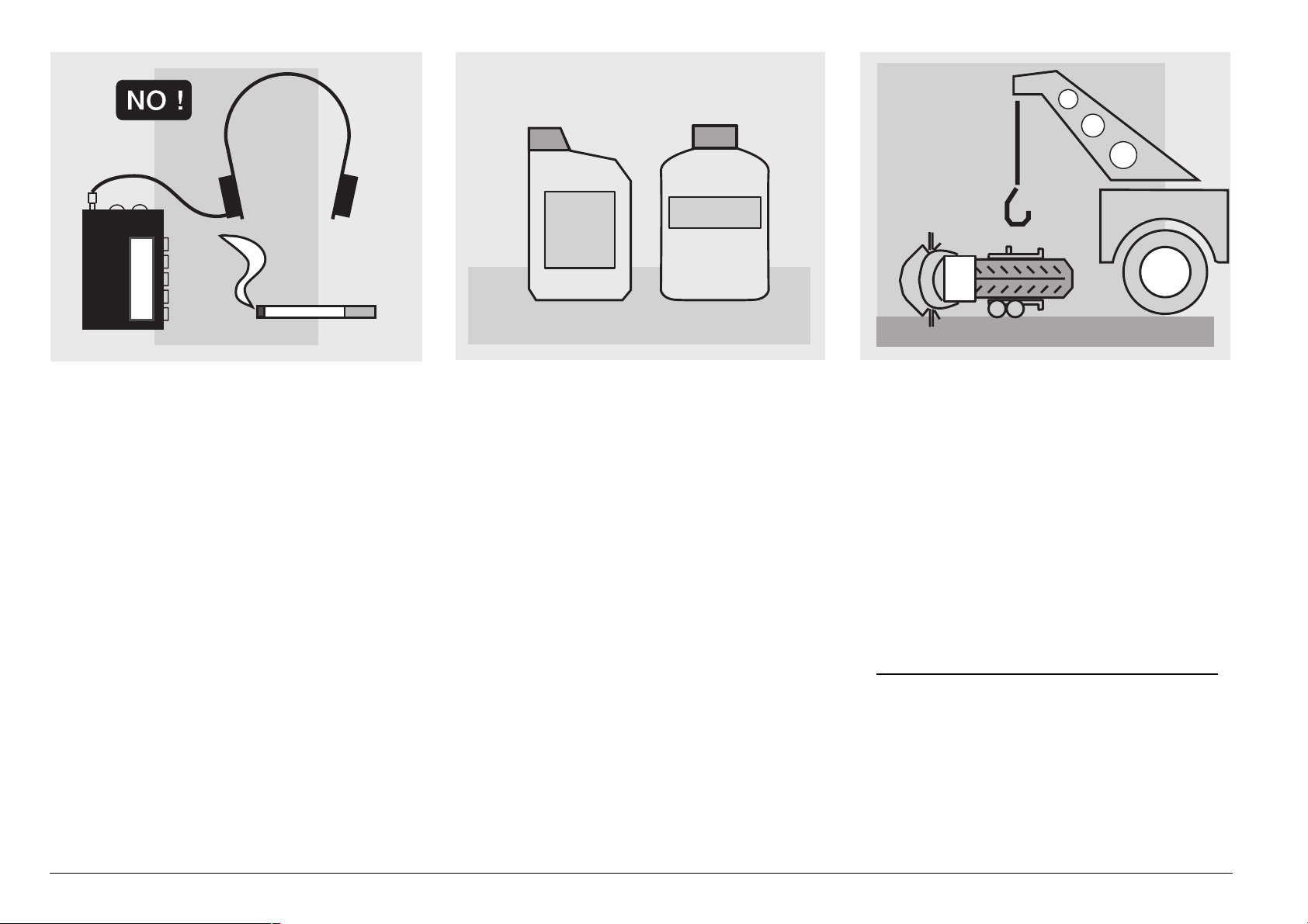
The driver should pay attention and avoid
distractions caused by people, things and
movements (never smoke, eat, drink, read,
etc.) while driving.
Use only the vehicle’s specific fuels and lubricants indicated in the "LUBRICANT
CHART"; check all oil, fuel and coolant levels regularly.
If the vehicle has been involved in an accident, make sure that no damage has occurred to the control levers, pipes, wires,
braking system and vital parts.
If necessary, have the vehicle inspected by
an aprilia Official Dealer, who should care-
fully check the frame, handlebars, suspensions, safety parts and all the devices that
you cannot check by yourself.
Always remember to report any malfunction to the technicians to help them in their
work.
Never use the vehicle when the amount of
damage it has suffered endangers your
safety.
Never change the position, inclination or
colour of: number plate, direction indicators, lights and horns.
Any modification of the vehicle will result in
the invalidity of the guarantee.
For only vehicles up to 50 cm3 included
Any modification of the engine or of other
members which is aimed at increasing the
speed or the power of the vehicle is prohibited by the law; in fact, any modification resulting in an increase of the maximum
speed or of the engine displacement would
change the scooter into a motorcycle,
use and maintenance SR 50 - SR 125 - SR 150
8
Page 9

A
ONLY ORIGINALS
2
1
5
4
3
which implies the following obligations for
the owner:
– new homologation;
– new registration;
– appropriate driving license.
Further, said modifications cause the loss
of the insurance cover, since insurance
policies expressly prohibit to make technical changes aimed at increasing the vehicle performance levels.
For the reasons stated above, the failure to
comply with the tampering prohibition is
punished by law with appropriate sanctions
(including the confiscation of the vehicle),
which, according to the case, can be combined with the sanctions provided for not
using the crash helmet and/or the number
plate, for the violation of fiscal obligations
(ownership tax) and with penal sanctions
provided for using the vehicle without driving license.
For only vehicles over 50 cm
Any modification of the vehicle and/or the
removal of original components can compromise vehicle performance levels and
safety or even make it illegal.
We recommend respecting all regulations
and national and local provisions regarding
the equipment of the vehicle.
In particular, avoid all modifications that increase the vehicle’s performance levels or
alter its original characteristics.
Never race with other vehicles.
Avoid off-road driving.
3
#,/4().'
Before starting, always wear a correctly
fastened crash helmet. Make sure that it is
homologated, in good shape, of the right
size and that the visor is clean.
Wear protective clothing, preferably in light
and/or reflecting colours.
In this way you will make yourself more visible to the other drivers, thus notably reducing the risk of being knocked down, and
you will be more protected in case of fall.
This clothing should be very tight-fitting
and fastened at the wrists and ankles.
Strings, belts and ties should not be hanging loose; prevent these and other objects
from interfering with driving by getting entangled with moving parts or driving mechanisms.
use and maintenance SR 50 - SR 125 - SR 150
9
Page 10
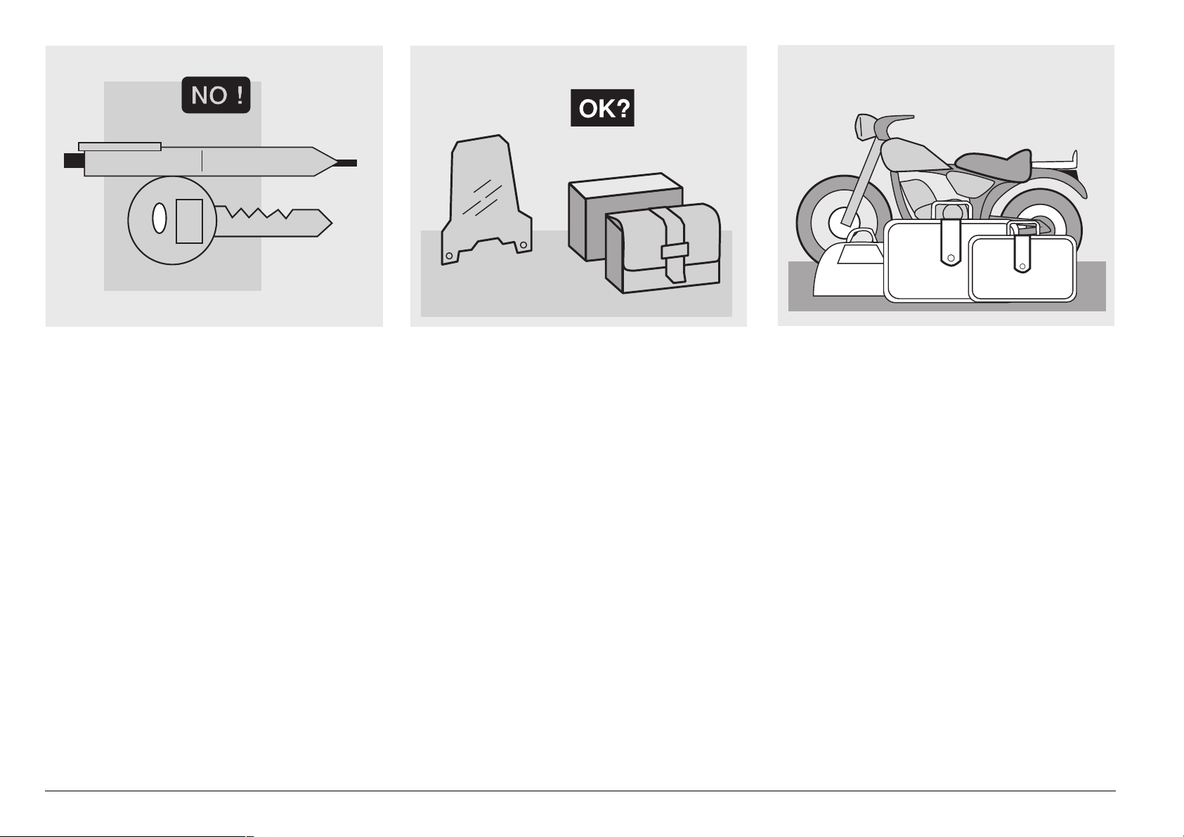
Do not keep objects that can be dangerous
in case of fall, for example pointed objects
like keys, pens, glass vials etc. in your
pockets (the same recommendations also
apply to passengers).
!##%33/2)%3
The owner of the vehicle is responsible for
the choice, installation and use of any accessory.
Avoid installing accessories that cover
horns or lights or that could impair their
functions, limit the suspension stroke and
the steering angle, hamper the operation of
the controls and reduce the distance from
the ground and the angle of inclination in
turns.
Avoid using accessories that hamper access to the controls, since this can prolong
reaction times during an emergency.
Big fairings and windshields installed on
the vehicle may produce aerodynamic forces that affect the stability of the vehicle, especially when riding at high speed.
Make sure that the equipment is well fastened to the vehicle and not dangerous
during driving. Do not install electrical devices and do not modify those already existing to avoid electrical overloads, because the vehicle could suddenly stop or
there could be a dangerous current shortage in the horn and in the lights.
aprilia recommends the use of “aprilia
genuine accessories”.
,/!$
Be careful and moderate when loading
your luggage. Keep any luggage loaded as
close as possible to the center of gravity of
the vehicle and distribute the load uniformly on both sides, in order to reduce imbalance to the minimum. Furthermore, make
sure that the load is firmly secured to the
vehicle, especially during long trips.
use and maintenance SR 50 - SR 125 - SR 150
10
Page 11
KG!
Avoid hanging bulky, heavy and/or dangerous objects on the handlebars, mudguards
and forks: the vehicle might respond more
slowly in turns and its manoeuvrability
could be unavoidably impaired.
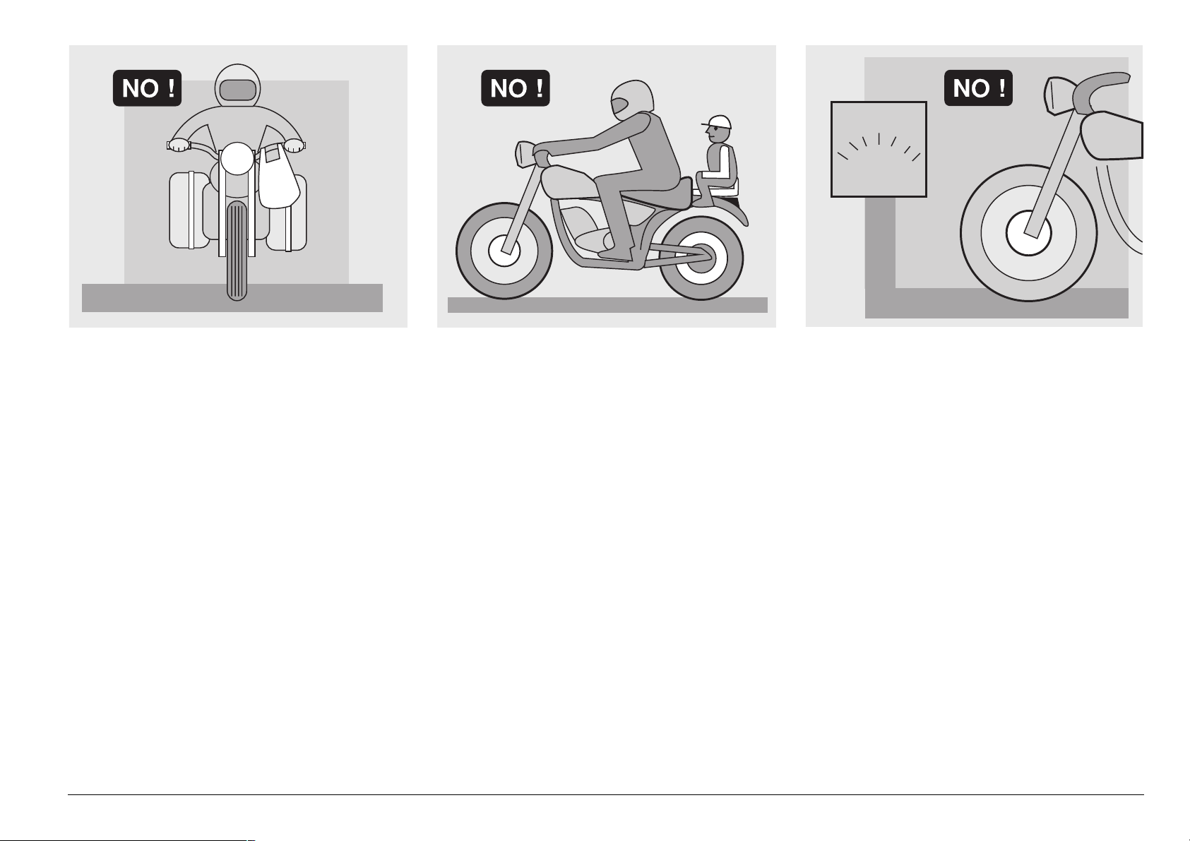
Do not place bags that are too bulky on the
vehicle sides, because they could hit people or obstacles, making you lose control of
the vehicle.
Do not carry any bag if it is not tightly secured to the vehicle.
Do not carry bags which protrude too much
from the luggage-rack or which cover the
lights, horn or indicators.
Do not carry animals or children on the
glove compartment or on the luggagerack.
Do not exceed the maximum load allowed
for each side-bag.
When the vehicle is overloaded, its stability
and its manoeuvrability can be compromised.
use and maintenance SR 50 - SR 125 - SR 150
11
Page 12
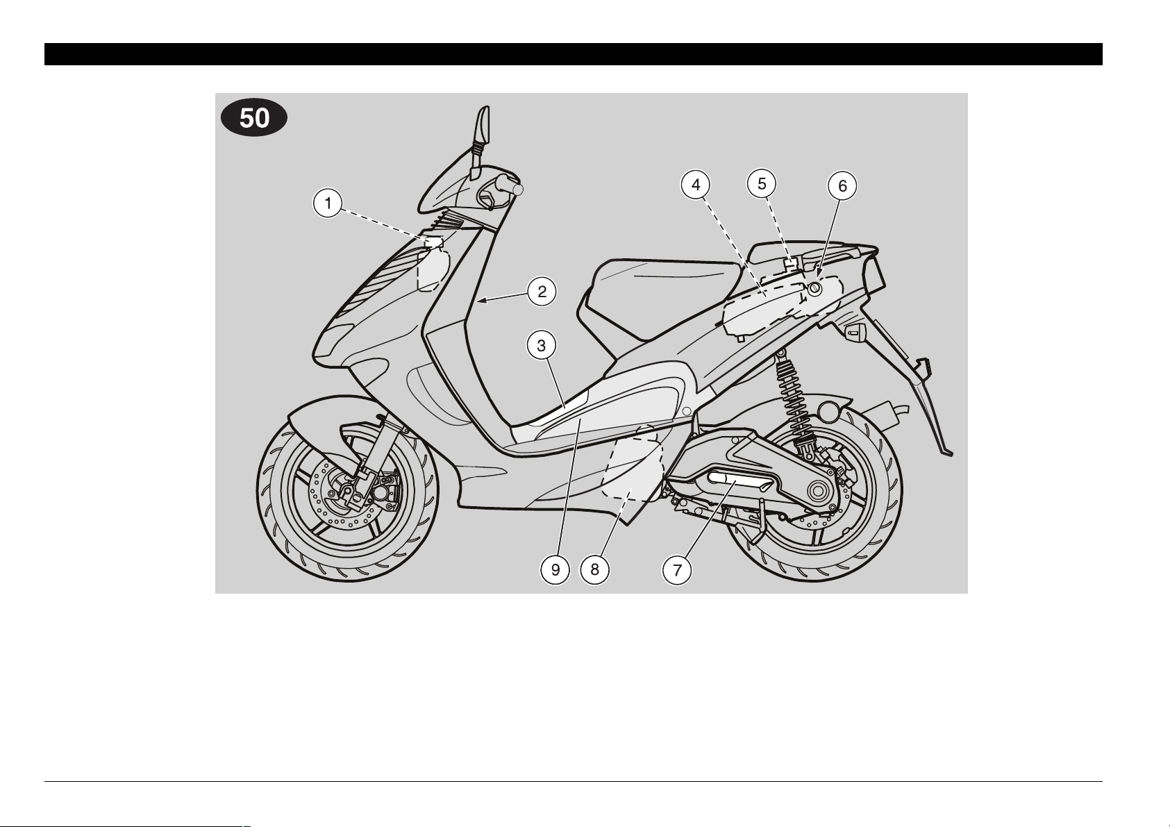
!22!.'%-%.4/&4(%-!).%,%-%.43
.
+%9
1) Coolant expansion tank plug
2) Bag hook
3) Battery/tool kit compartment cover
4) Fuel tank
5) Fuel tank plug
use and maintenance SR 50 - SR 125 - SR 150
12
1
6) Saddle lock
7) Kick starter
8) Air cleaner
9) Left inspection cover
Page 13
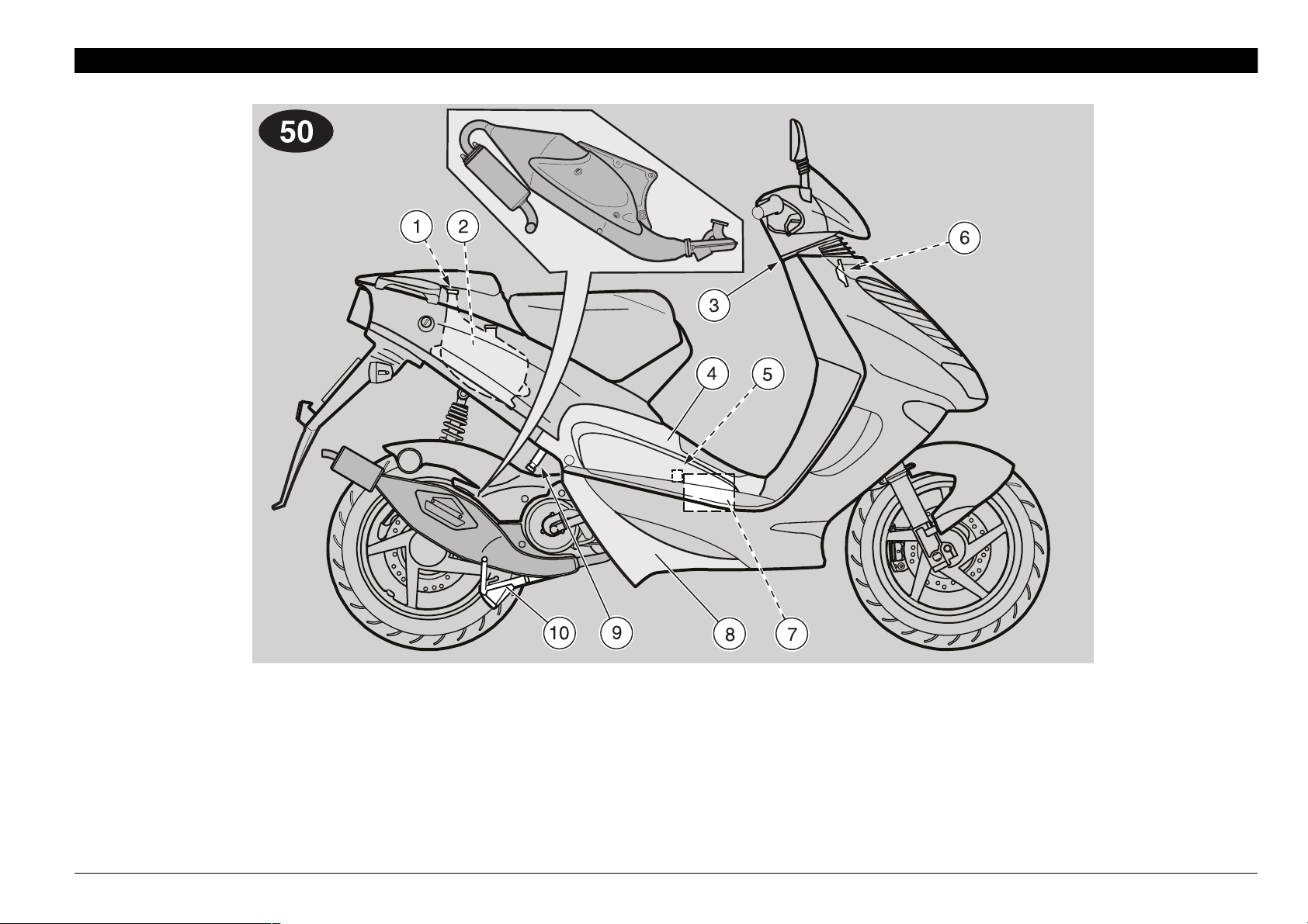
+%9
1) 2 stroke oil tank plug
2) 2 stroke oil tank
3) Ignition switch/steering lock
4) Right inspection cover
5) Fuse carrier
6) Horn
7) Battery
8) Lower shield cover
9) Anti-theft hook (for the aprilia “Body-
Guard” armored cable
10) Centre stand
&).
use and maintenance SR 50 - SR 125 - SR 150
13
Page 14
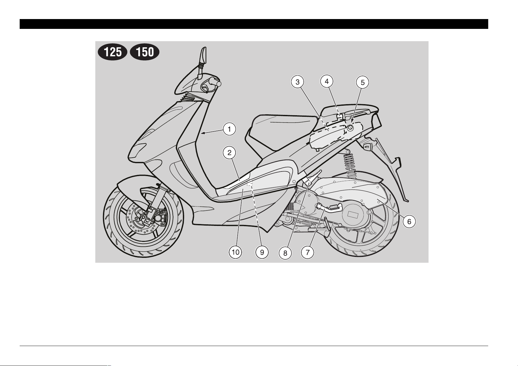
!22!.'%-%.4/&4(%-!).%,%-%.43
+
+%9
1) Bag hook
2) Battery/tool kit compartment cover
3) Fuel tank
4) Fuel tank plug
5) Saddle lock
use and maintenance SR 50 - SR 125 - SR 150
14
6) Air cleaner
7) Kick starter
8) Passenger left footrest
9) Fuse carrier
10) Left inspection cover
Page 15
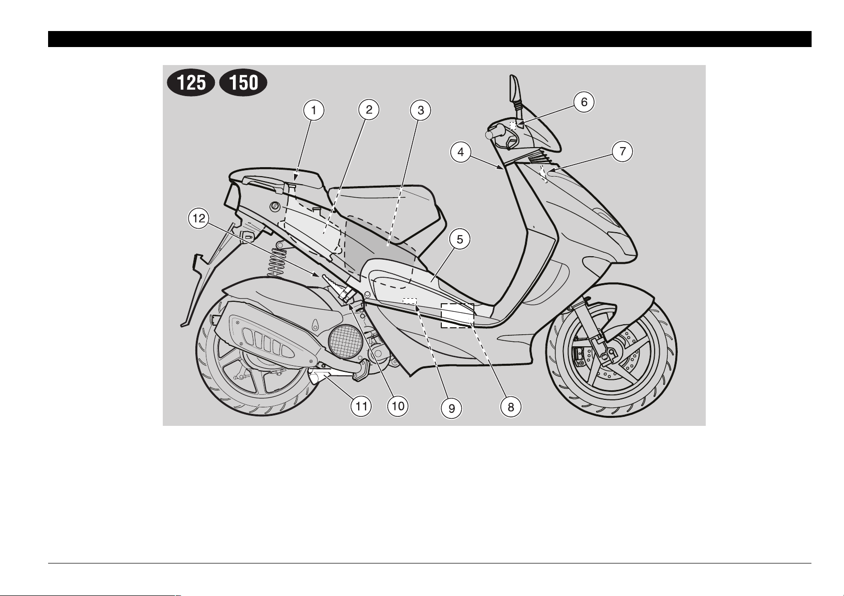
+%9
1) 2 stroke oil tank plug
2) 2 stroke oil tank
3) Crash helmet / glove compartment
4) Ignition switch/steering lock
5) Right inspection cover
6) Brake fluid reservoir (front brake)
7) Horn
8) Battery
9) Spark plug
10) Anti-theft hook (for the aprilia “Body-
Guard” armored cable
11) Centre stand
12) Passenger right footrest
&).
use and maintenance SR 50 - SR 125 - SR 150
15
Page 16
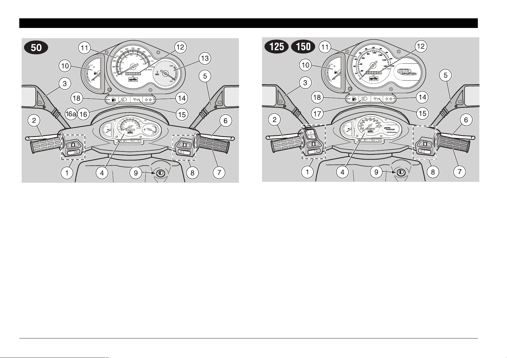
!22!.'%-%.4/&4(%#/.42/,3 ). 34 25- %.4 3 !.$ ). $) #!4 /2 3
+%9
1) Electrical controls on the left side of the handlebar
2) Rear brake lever
3) Left rear-view mirror
4) Instruments and indicators
5) Right rear-view mirror
6) Throttle grip
7) Front brake lever
8) Electrical controls on the right side of the handlebar
9) Ignition switch/steering lock (
use and maintenance SR 50 - SR 125 - SR 150
16
n - m - s)
10) Fuel level indicator (
11) Speedometer
12) Total kilometres odometer
13)
14) Green direction indicator warning light (c)
15) Red 2 stroke oil reserve warning light (
16)
16a)
17)
18) Amber low fuel warning light (
Coolant temperature indicator (h)
.
Green low beam warning light (b)
.
Blue high beam warning light (a) C % K - _
.
+
Blue high beam warning light (a)
g)
1
j)
g)
Page 17
).3425-%.4!.$).$)#!4/24!",%
Description Function
Direction indicator warning light (
2 stroke oil reserve warning light (
Total kilometres odometer It indicates the total number of kilometres covered.
Speedometer It indicates the driving speed.
Low beam warning light (
.
High beam warning light
.
C % K - _
+
Low fuel warning light (
High beam warning light (a) It comes on when the headlight in high beam position.
c) It blinks when the direction indicators are on.
It comes on when the ignition switch is in position “
“
r“ is pressed, thus checking the proper functioning of the bulb.
If the light does not come on during the starting, provide for replacing the bulb.
j)
aCAUTION
or if it comes on during normal functioning, this means that the 2 stroke
oil reserve is being used; in this case, top up the 2 stroke oil tank, see
p. 26 (2 STROKE OIL).
If the warning light comes on and does not go out
after the start push button “
b) It comes on when the headlight is in low beam position.
(a)
It comes on when the headlight in high beam position.
g) It comes on when the quantity of fuel left in the tank is about 2 L.
n” and the start push button
r” has been released,
Fuel level indicator (
Coolant temperature indicator
.
1
g) It indicates the approximate fuel level in the tank.
It indicates the approximate temperature of the coolant in the engine.
When the pointer starts moving beyond the “min” level, the temperature is sufficient for driving the vehicle.
The normal running temperature range is indicated by the central area of the
(h)
scale.
If the pointer reaches the red area, stop the engine and check the coolant level,
see p. 30 (
aCAUTION
COOLANT 1).
.
If the maximum allowed temperature is exceeded
(red area “max” of the scale), the engine may be
seriously damaged.
use and maintenance SR 50 - SR 125 - SR 150
17
Page 18
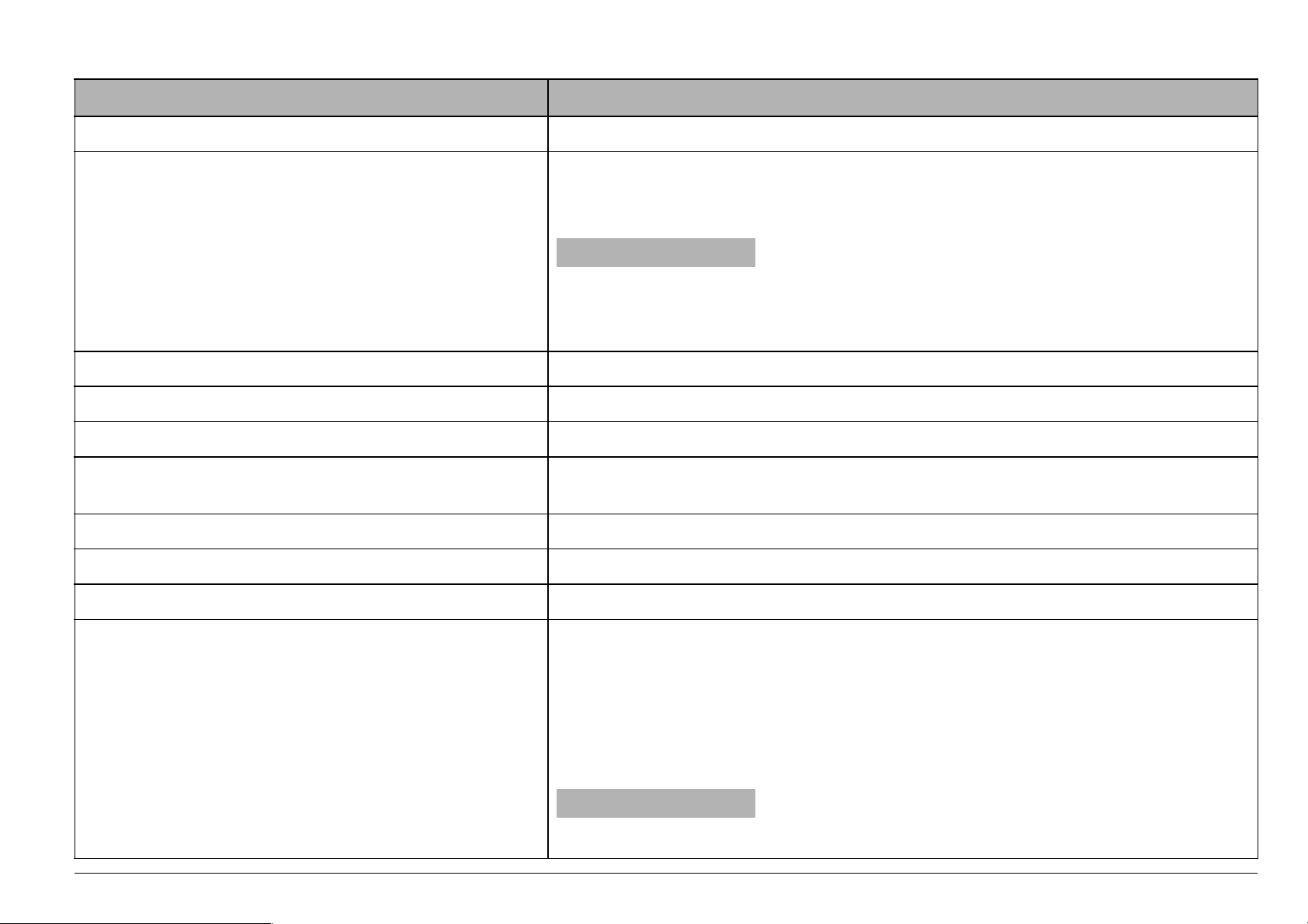
-!).).$%0%.$%.4#/.42/,3
.
#/.42/,3/.4(%,%&43)$%/&4(%(!.$,%"!2
NOTE The electrical parts work only when the ignition switch
is in position “
n”.
NOTE The lighting system works only when the engine is run-
ning.
1) HORN PUSH BUTTON (
The horn is activated when the push button is pressed.
2) COLD START LEVER (
The starter for the cold start of the engine is operated by rotating the lever downwards.
To disconnect the cold start, bring the lever to its initial position.
3) DIRECTION INDICATOR SWITCH (
To indicate the turn to the left, move the switch to the left; to
indicate the turn to the right, move the switch to the right.
To turn off the direction indicator, press the switch.
4) DIMMER SWITCH (
(in the countries where the engine stop switch is required
m - n”)
“
When it is in position “
light and the low beam are always on.
When it is in position “
f)
e)
c)
a - b )
b” the parking lights, the dashboard
a”, the high beam comes on.
use and maintenance SR 50 - SR 125 - SR 150
18
NOTE The lights can be switched off only by stopping the
engine.
Page 19
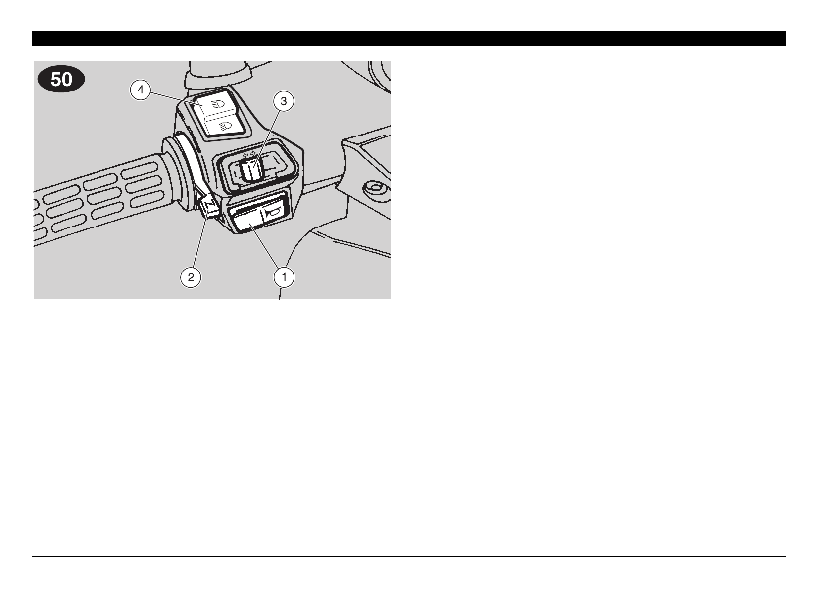
#/.42/,3/.4(%2)'(43)$%
/&4(%(!.$,%"!2
NOTE The electrical parts work only when the ignition switch
is in position “
n”.
NOTE The lighting system works only when the engine is run-
ning.
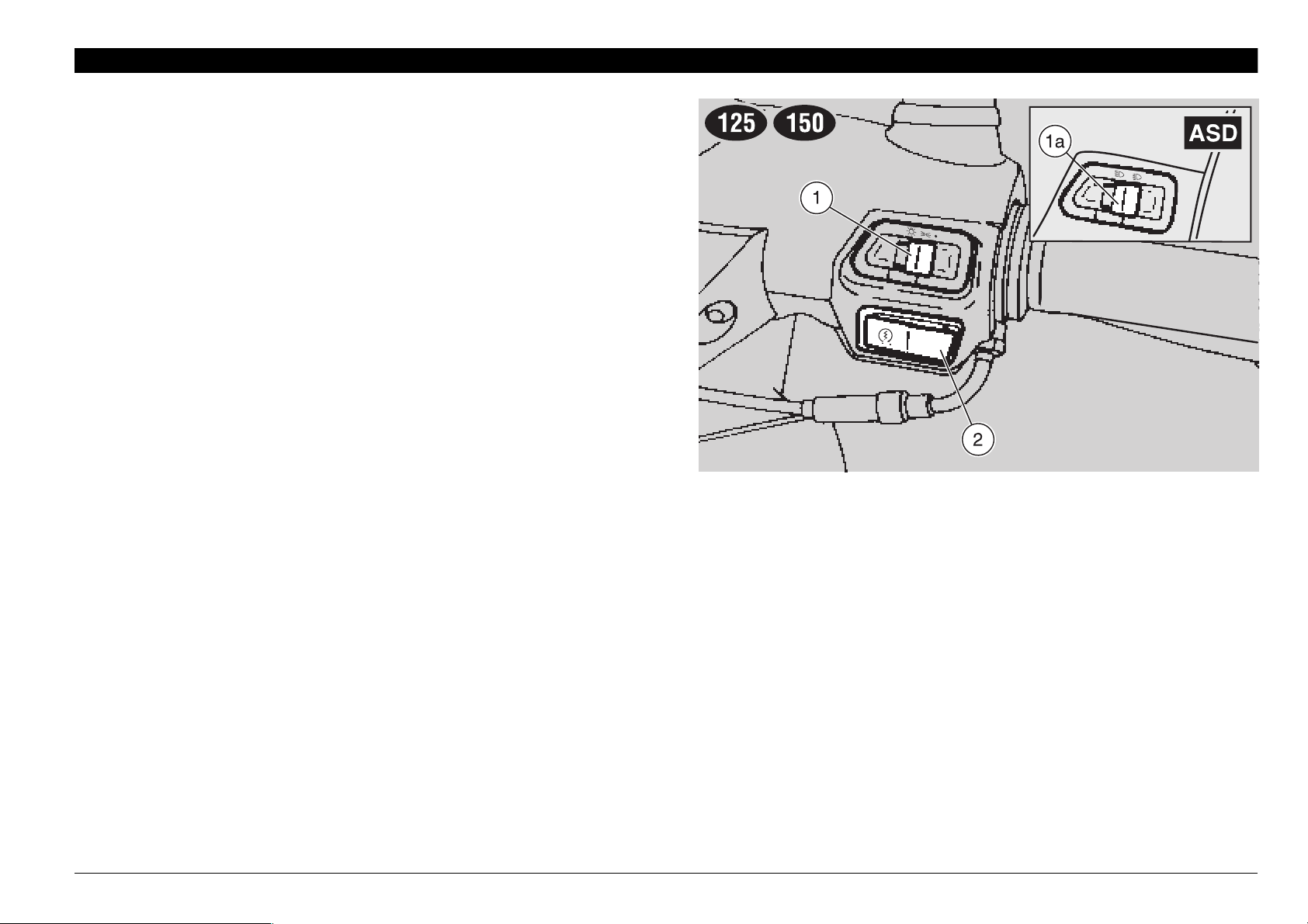
1) LIGHT SWITCH (
When the light switch is in position “
the switch is in position “
beam are on.
1a) LIGHT SWITCH (
When the light switch is in position “•”, the lights are off;
when the switch is in position “
parking lights are on; when it is in position “
beam and the parking lights are on.
1b) DIMMER SWITCH (
(not provided for those countries where the engine
stop switch “
When the dimmer switch is in position “
and the parking lights are on; when it is in position “
high beam and the parking lights are on.
b -
m - n” is required)
) (
•
not provided)
_
•
”, the lights are off; when
b”, the rear parking light and the low
a - b -
) C % K
•
b” the low beam and the
a” the high
a - b )
_
b”, the low beam
a”, the
NOTE The lights can be switched off only by stopping the
engine.
1c) ENGINE STOP SWITCH (
(in the countries where required)
n - m)
aCAUTION
Do not operate the engine stop switch “n - m” in running
conditions.
This is a safety or emergency switch. With the switch in position “
be stopped by moving the switch to position “
n”, it is possible to start the engine; the engine can
m”.
aCAUTION
With stopped engine and ignition switch in position “n”,
the battery may run down.
When the vehicle has come to a halt, stop the engine, and
move the ignition switch to position “
2) START PUSH BUTTON (
When the start push button is pressed and one of the brake
levers (front or rear) is activated at the same time, the starter
makes the engine run.
For the starting procedure, see p. 36 (STARTING).
r)
m”.
use and maintenance SR 50 - SR 125 - SR 150
19
Page 20
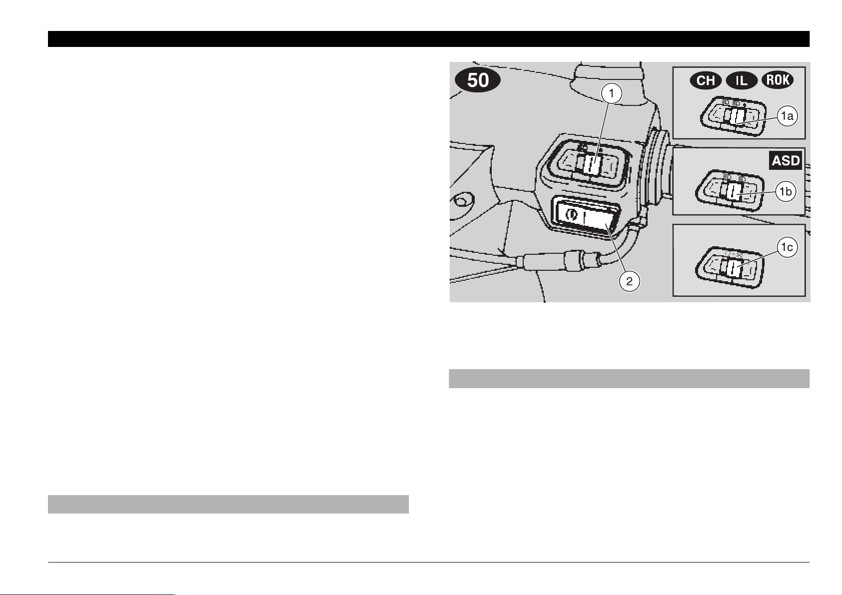
-!).).$%0%.$%.4#/.42/,3
+
#/.42/,3/.4(%,%&43)$%/&4(%(!.$,%"!2
NOTE The electrical parts work only when the ignition switch
is in position “
n”.
1) HORN PUSH BUTTON (
The horn is activated when the push button is pressed.
2) DIMMER SWITCH (
When the light switch is in position “
is in position “
sition “
3) DIRECTION INDICATOR SWITCH (
To indicate the turn to the left, move the switch to the left; to
indicate the turn to the right, move the switch to the right.
To turn off the direction indicator, press the switch.
b”, the low beam comes on.
a”, the high beam comes on, while if it is in po-
f)
a - b ) (
not provided)
_
o”: if the dimmer switch
c)
use and maintenance SR 50 - SR 125 - SR 150
20
Page 21
#/.42/,3/.4(%2)'(43)$%
/&4(%(!.$,%"!2
NOTE The electrical parts work only when the ignition switch
is in position “
n”.
1) LIGHT SWITCH (
o - p -
) (J not provided)
•
NOTE Before operating the light switch, make sure that the
dimmer switch (
When the light switch is in position “
the switch is in position “
board light are on; when the switch is in position “
parking lights, the dashboard light and the low beam are on.
The high beam can be operated by means of the dimmer
switch (
1a) DIMMER SWITCH (
When it is in position “b ” the parking lights, the dashboard
light and the low beam are always on.
When it is in position “
2) START PUSH BUTTON (
When the start push button is pressed and one of the brake
levers (front or rear) is activated at the same time, the starter
makes the engine run.
For the starting procedure, see p. 36 (STARTING).
a - b).
a - b ) is in position “ b”.
”, the lights are off; when
•
p”, the parking lights and the dash-
a - b )
_
a”, the high beam comes on.
r)
o”, the
use and maintenance SR 50 - SR 125 - SR 150
21
Page 22
Position Function
Key
removal
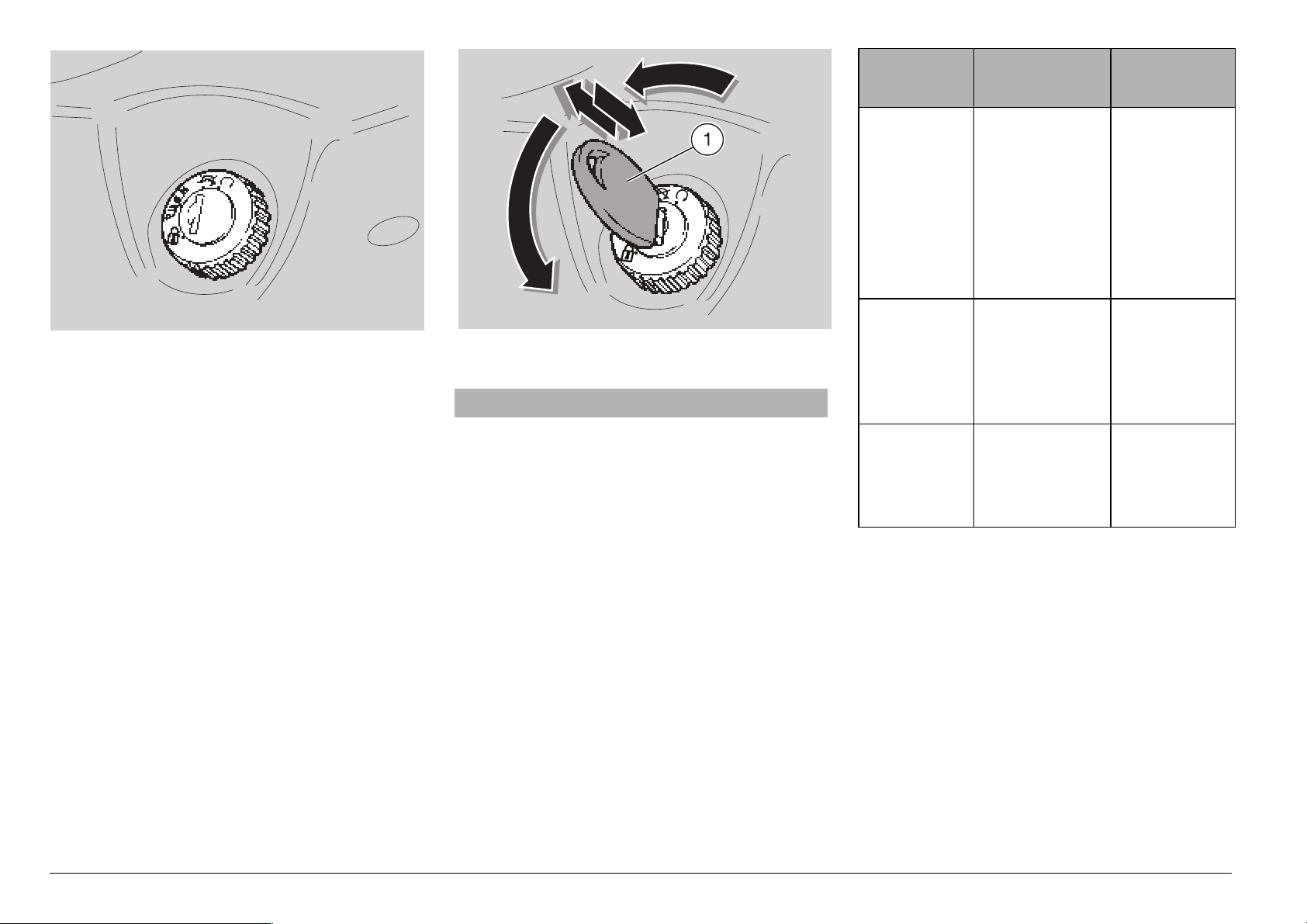
)'.)4)/.37)4#(
The ignition switch is positioned on the
right side, near the steering column.
NOTE The key (1) operates the igni-
tion/steering lock switch, the battery/tool kit
compartment lock and the saddle lock.
Two keys are supplied together with the
vehicle (one spare key).
NOTE Do not keep the spare key on the
vehicle.
34%%2).',/#+
aWARNING
Never turn the key to position “s” in
running conditions, in order to avoid
losing control of the vehicle.
OPERATION
To lock the steering:
◆
Turn the handlebar completely leftwards.
◆
Turn the key (1) to position “m” and
press it.
◆
Release the key.
s
Steering
lock
m
n
The steering
is locked.
It is neither
possible to
start the engine, nor to
switch on the
lights.
Neither the
engine, nor
the lights can
be switched
on.
The engine
and the lights
can be
switched on.
It is possible
to remove
the key.
It is possible
to remove
the key.
It is not possible to remove the
key.
use and maintenance SR 50 - SR 125 - SR 150
22
NOTE Turn the key and steer the han-
dlebar at the same time.
◆
Rotate the key (1) anticlockwise (leftwards), steer the handlebar slowly until
the key (1) reaches position “
◆
Extract the key.
s”.
Page 23
!58),)!29%15)0-%.4
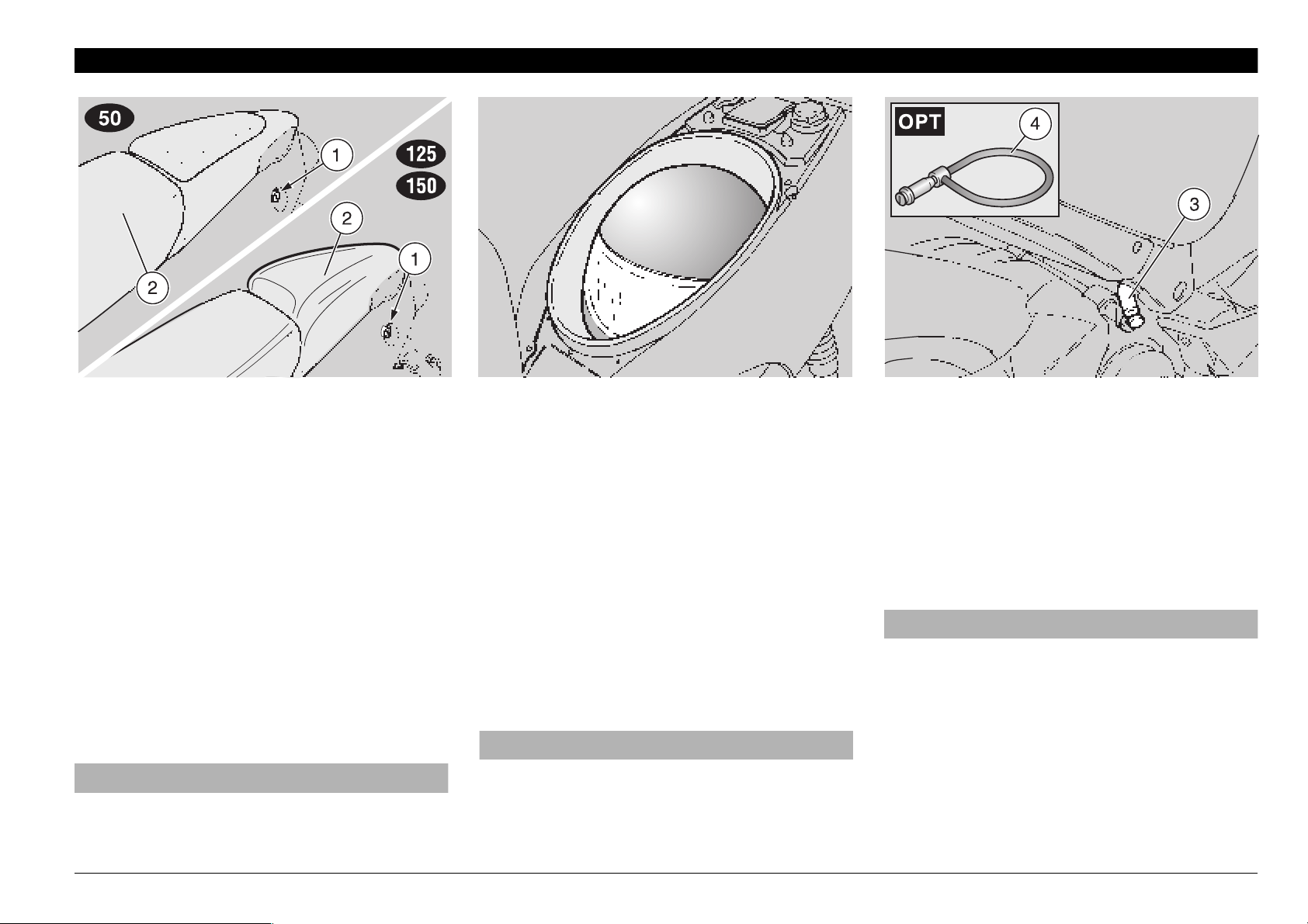
5.,/#+).',/#+).'
4(%3!$$,%
To unlock and lift the saddle:
◆
Position the vehicle on the stand.
◆
Insert the key in the saddle lock (1).
◆
Turn the key clockwise and raise the
saddle (2).
NOTE Before lowering and locking the
saddle, make sure that you have not left
the key in the crash helmet / glove compartment.
◆
To lock the saddle, lower and press it
(without exerting too much pressure),
thus making the lock snap shut.
aWARNING
Before leaving, make sure that the saddle is properly locked.
#2!3((%,-%4',/6%
#/-0!24-%.4
Thanks to the crash helmet/glove compartment, you no longer have to carry the
crash helmet or other objects with you every time you park the vehicle. The compartment is positioned under the saddle.
To reach it:
◆
Raise the saddle (2), see beside (UNLOCKING / LOCKING THE SADDLE).
NOTE Position the helmet with the
opening facing downwards, as indicated in
the figure.
aWARNING
Do not load the crash helmet / glove
compartment too much.
Maximum allowed weight: 2.5 kg.
!.4)4(%&4(//+
The anti-theft hook (3) is positioned on the
right side of the vehicle, near the rider’s
footboard.
To prevent the vehicle from being stolen, it
is advisable to secure it with the aprilia
“Body-Guard” armored cable
able at any aprilia Official Dealer.
(4), avail-
&
aWARNING
Do not use the hook to lift the vehicle or
for any purpose other than securing the
vehicle once it has been parked.
use and maintenance SR 50 - SR 125 - SR 150
23
Page 24

"!44%294//,+)4
#/-0!24-%.4
This compartment is positioned in the lower part of the vehicle, between the footrests.
To reach it, proceed as follows:
◆
Insert the key (1) in the lock.
◆
Rotate the key (1) clockwise, pull it and
remove the cover (2).
The tool kit (3) includes:
– n. 1 tool case
– n. 1 21 mm spark plug socket spanner
– n. 1 socket spanner rod
– n. 1 double-ended, cross-/cut headed-
screwdriver type PH size 2
– n. 1 screwdriver handle
– n. 1
– n. 1
. 4 mm hexagon spanner
. 8/10 mm socket spanner
"!'(//+
aWARNING
Do not hang excessively bulky bags or
parcels to the hook, as this may seriously compromise the manoeuvrability of
the vehicle or the movement of your feet.
The bag hook (4) is positioned on the front
part of the inner shield.
Max. allowed weight: 1.5 kg.
2%!2-5$'5!2$%84%.3)/.
The rear mudguard extension (5) is provided as standard equipment and can be installed if the vehicle is used on wet roads,
since it reduces the reach of the water
spray caused by the rear wheel.
NOTE The rear mudguard extension (5),
complete with screws and relevant nuts, is
supplied as standard equipment and is
housed in the crash helmet/glove compartment.
For the installation, see p. 56 (
ING THE REAR MUDGUARD EXTENSION), see p. 57 (
THE REAR MUDGUARD EXTENSION).
+
%84%.3)/.3
In the countries where the number plate
size is 280x280 mm, it is necessary to install appropriate extensions (6) for the direction indicators.
$)2%#4)/.).$)#!4/2
+
INSTALL-
.
INSTALLING
NOTE The direction indicator extensions
(6), complete with nuts and screws, are
supplied as standard equipment and are
housed in the crash helmet/glove compartment.
For the installation, see p. 58 (
STALLING THE DIRECTION INDICATOR
EXTENSIONS).
+
IN-
use and maintenance SR 50 - SR 125 - SR 150
24
Page 25
-!).#/-0/.%.43
&5%,
aWARNING
The fuel used for internal combustion
engines is extremely inflammable and
in particular conditions it can become
explosive. It is important to carry out
the refuelling and the maintenance operations in a well-ventilated area, with
the engine off. Do not smoke while refuelling or near fuel vapours, in any case
avoid any contact with naked flames,
sparks and any other heat source to
prevent the fuel from catching fire or
from exploding.
Further, prevent fuel from flowing out of
the fuel filler, as it could catch fire when
getting in contact with the red-hot surfaces of the engine.
In case some fuel has accidentally been
spilt, make sure that the area is completely dry before starting the vehicle.
Since petrol expands under the heat of
the sun and due to the effects of sun radiation, never fill the tank to the brim.
Screw the cap carefully after refuelling.
Avoid any contact of the fuel with the
skin and the inhalation of vapours; do
not swallow fuel or pour it from a receptacle into another by means of a tube.
DO NOT DISPOSE OF FUEL IN THE ENVIRONMENT.
KEEP AWAY FROM CHILDREN.
.
Use only premium grade petrol (4 Stars
), in conformity with the DIN 51600
U
standard, min. O.N. 98 (N.O.R.M.) and 88
(N.O.M.M.).
2 Use only unleaded petrol, in conformity
with the DIN 51607 standard, min. O.N. 95
(N.O.R.M.) and 85 (N.O.M.M.).
+
Use only unleaded petrol, in conformity
with the DIN 51607 standard, min. O.N. 95
(N.O.R.M.) and 85 (N.O.M.M.).
FUEL TANK CAPACITY
(reserve included): 8
TANK RESERVE: 2 L
To refuel, proceed as follows:
◆
Position the vehicle on the centre stand.
◆
Lift the saddle, see p. 23 (UNLOCKING /
LOCKING THE SADDLE).
◆
Unscrew and remove the fuel tank plug
(1).
◆
Refuel.
L
aWARNING
After refuelling, put back the cap (1) in
the correct position.
◆
Put back the cap (1).
use and maintenance SR 50 - SR 125 - SR 150
25
Page 26
,5"2)#!.43
aWARNING
Oil can cause serious damage to the
skin if handled every day and for long
periods.
Wash your hands carefully after using
oil.
In case any maintenance operation has
to be carried out, it is advisable to use
latex gloves.
KEEP AWAY FROM CHILDREN.
DO NOT DISPOSE OF OIL IN THE ENVIRONMENT.
aCAUTION
Proceed with care.
Do not spill the oil!
Take care not to smear any component,
the area in which you are working and
the surrounding area.
Carefully remove any trace of oil.
aCAUTION
In case of leakages or malfunctions,
contact an APRILIA Official Dealer.
2 STROKE OIL
Top up the 2 stroke oil tank every 500 km
(312 mi).
The vehicle is provided with a separate
mixer that makes it possible to mix petrol
with oil for the lubrication of the engine, see
p. 84 (x LUBRICANT CHART) or p. 85
(z { LUBRICANT CHART).
The reserve is indicated by the coming on of
the 2 stroke oil reserve warning light “
positioned on the dashboard, see p. 16 and
17 (ARRANGEMENT OF THE CONTROLS
/ INSTRUMENTS AND INDICATORS).
j”
aCAUTION
The use of the vehicle without 2 stroke
oil causes serious damages to the engine.
If you run out of oil in the 2 stroke oil
tank or if the 2 stroke oil pipe has been
removed, it is necessary to contact an
APRILIA Official Dealer, who will provide
for bleeding the system.
This operation is indispensable, since
the operation of the engine with air in
the 2 stroke oil system may cause serious damages to the engine itself.
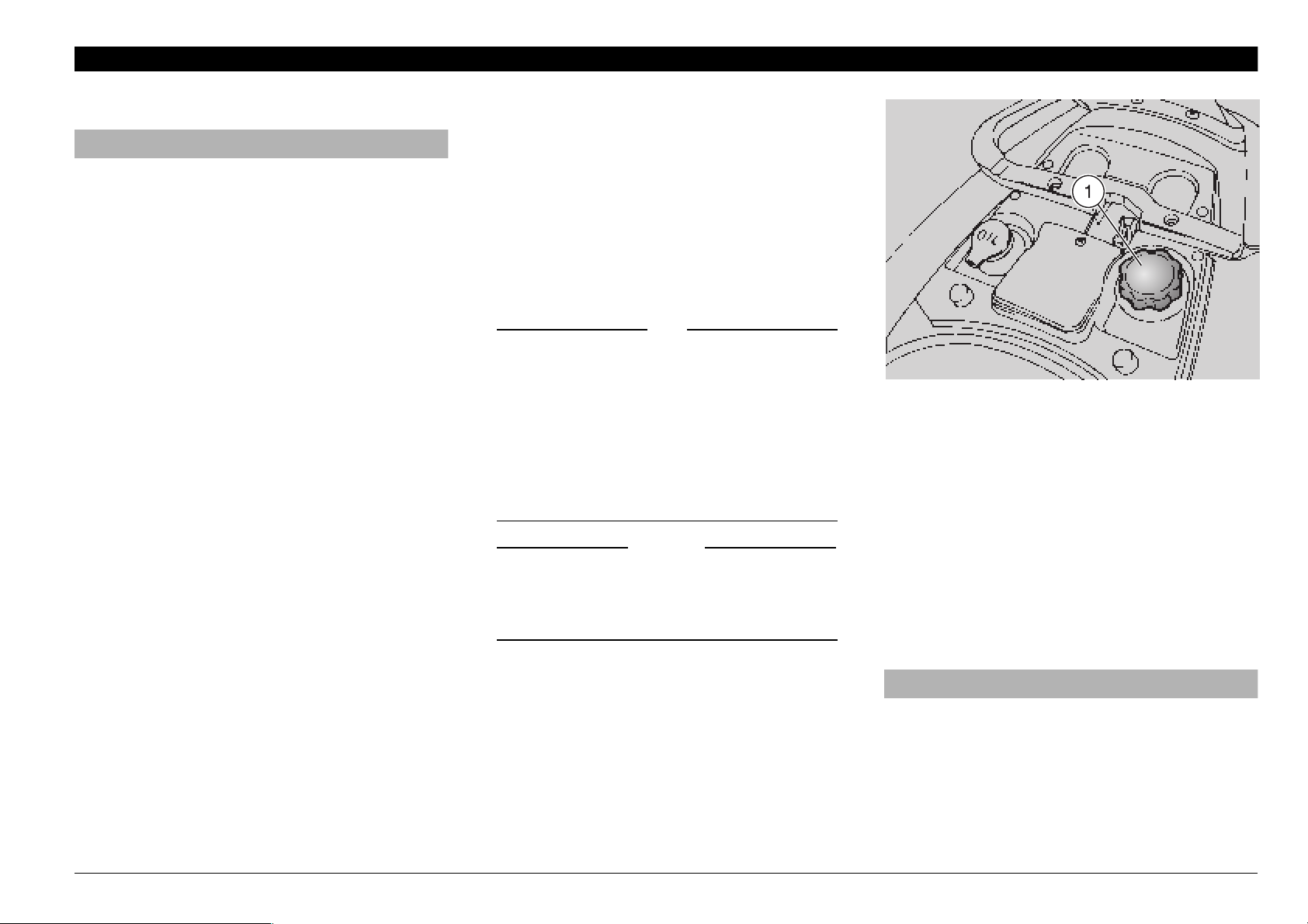
To top up the 2 stroke oil tank, proceed as
follows:
◆
Position the vehicle on the centre stand.
◆
Lift the saddle, see p. 23 (UNLOCKING /
LOCKING THE SADDLE).
◆
Remove the plug (1).
2 STROKE OIL TANK CAPACITY: 1.6
TANK RESERVE: 0.5 L
◆
Top up the 2 stroke oil tank.
L
aWARNING
After refuelling, put back the cap (1) in
the correct position.
◆
Put back the cap (1).
use and maintenance SR 50 - SR 125 - SR 150
26
Page 27
TRANSMISSION OIL
.
Have the transmission oil level checked
every 4000 km (2500 mi), or every 12
months.
It is necessary to have the transmission oil
changed after the first 500 km (312 mi) and
successively every 12000 km (7500 mi), or
every 2 years.
To check the oil level and to change the oil,
contact an aprilia Official Dealer.
+
Have the transmission oil level checked
every 4000 km (2500 mi), or every 12
months.
It is necessary to have the transmission oil
changed after the first 1000km (625 mi)
and successively every 12000 km (7500
mi), or every 24 months.
To check the oil level and to change the oil,
contact an aprilia Official Dealer.
TRANSMISSION OIL
"2!+%&,5)$RECOMMENDATIONS
aWARNING
Sudden resistance or clearance problems on the brake lever may be due to
troubles in the hydraulic system.
For any doubt regarding the perfect
functioning of the braking system and
in case you are not able to carry out the
usual checking operations, contact
your APRILIA Official Dealer.
aWARNING
Pay special attention to the brake disc
and friction material, making sure that
they are neither dirty nor oily, especially
after maintenance operations or inspections.
Make sure that the brake pipe is neither
twisted nor worn out.
KEEP AWAY FROM CHILDREN.
DO NOT DISPOSE OF THE FLUID IN
THE ENVIRONMENT.
use and maintenance SR 50 - SR 125 - SR 150
27
Page 28
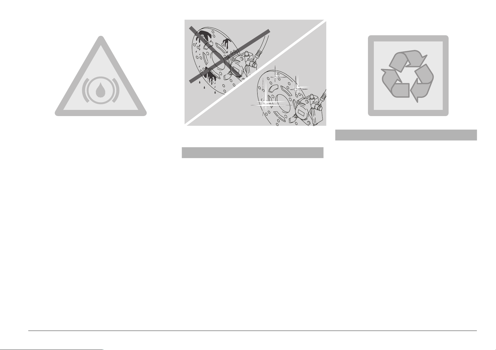
$)3#"2!+%3
aWARNING
The brakes are the parts that most ensure your safety and for this reason
they must always be perfectly working;
check them before every trip.
A dirty disc soils the pads, with consequent reduction of the braking efficiency. Dirty pads must be replaced, while
dirty discs must be cleaned with a highquality degreaser.
The brake fluid must be changed every
two years by an APRILIA Official Dealer.
For any doubt regarding the perfect
functioning of the braking system and
in case you are not able to carry out the
usual checking operations, contact
your APRILIA Official Dealer.
This vehicle is provided with hydraulic disc
brakes.
NOTE For the version with rear drum
brake
to the front disc brake only.
When the disc pads wear out, the level of
the fluid decreases to automatically compensate for their wear.
, the following information refers
3
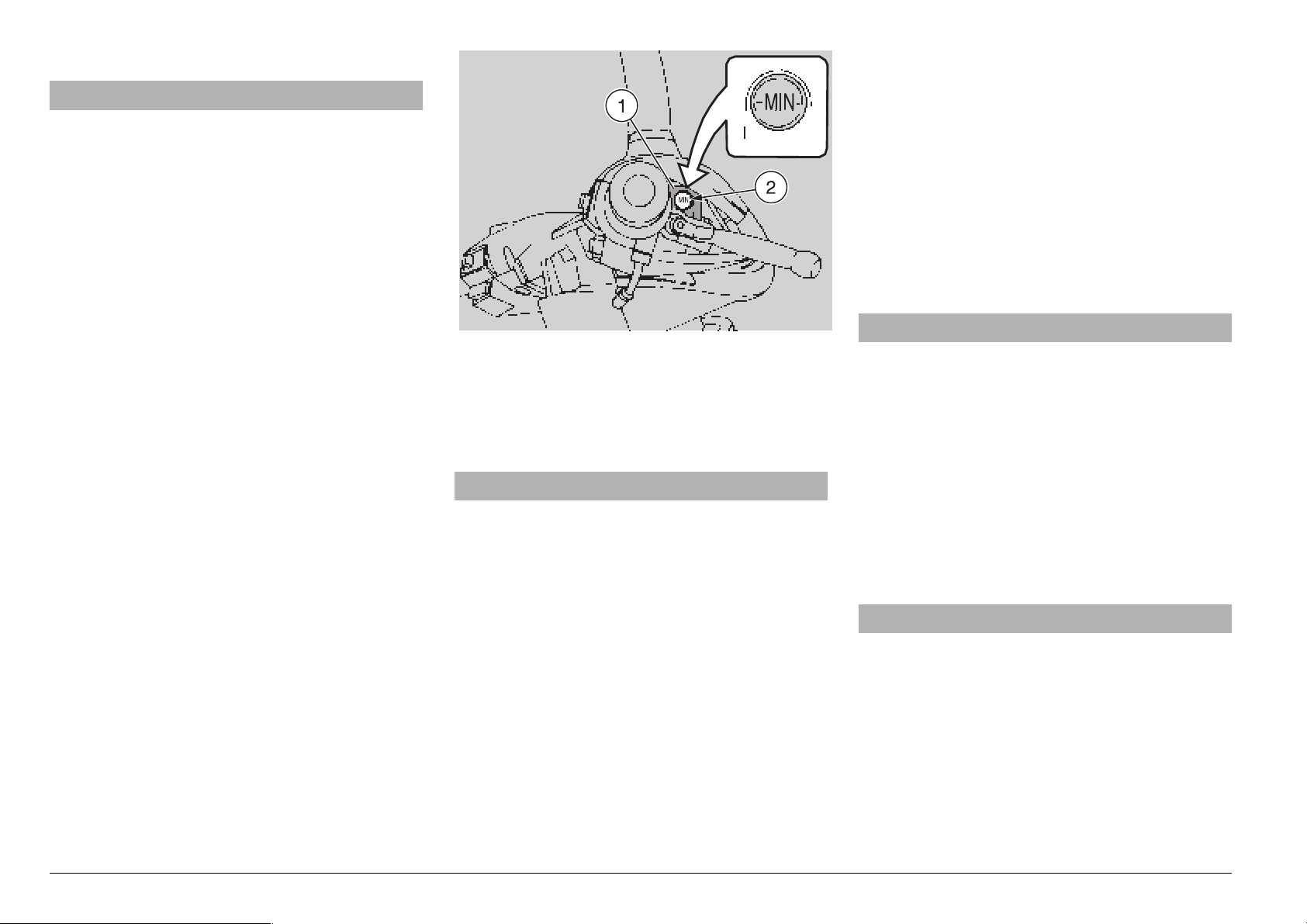
The brake fluid reservoir (1) is positioned
near the front brake lever coupling. Periodically check the brake fluid level in the reservoir (1) and the pad wear, see p. 51
(CHECKING THE BRAKE PAD WEAR).
aWARNING
Do not use the vehicle if the braking
system leaks fluid.
CHECKING
To check the brake fluid level, proceed as
follows:
NOTE Position the vehicle on firm and
flat ground.
MIN = minimum level.
◆
Position the vehicle on the centre stand.
◆
Rotate the handlebar, so that the fluid
contained in the brake reservoir is parallel to the “MIN” mark stamped on the
glass gauge (2).
◆
Make sure that the fluid contained in the
reservoir exceeds the “MIN” mark
stamped on the glass gauge (2).
If the fluid does not reach at least the “MIN”
mark:
aCAUTION
When the disc pads wear out, the level
of the fluid decreases progressively to
compensate for their wear.
◆
Check the brake pad wear, see p. 51
(CHECKING THE BRAKE PAD WEAR)
and the disc wear.
If the pads and / or the disc do not need replacing:
◆
Contact an aprilia Official Dealer, who
will provide for topping up.
aCAUTION
Check the braking efficiency.
In case of excessive stroke of the brake
lever or reduced efficiency of the braking system, contact an APRILIA Official
Dealer, since it may be necessary to
bleed the system.
use and maintenance SR 50 - SR 125 - SR 150
28
Page 29
2%!2$25-"2!+%
aWARNING
The brakes are the parts that most ensure your safety and for this reason
they must always be perfectly working.
For any doubt regarding the perfect
functioning of the braking system and
in case you are not able to carry out the
usual checking opAerations, contact
your APRILIA Official Dealer.
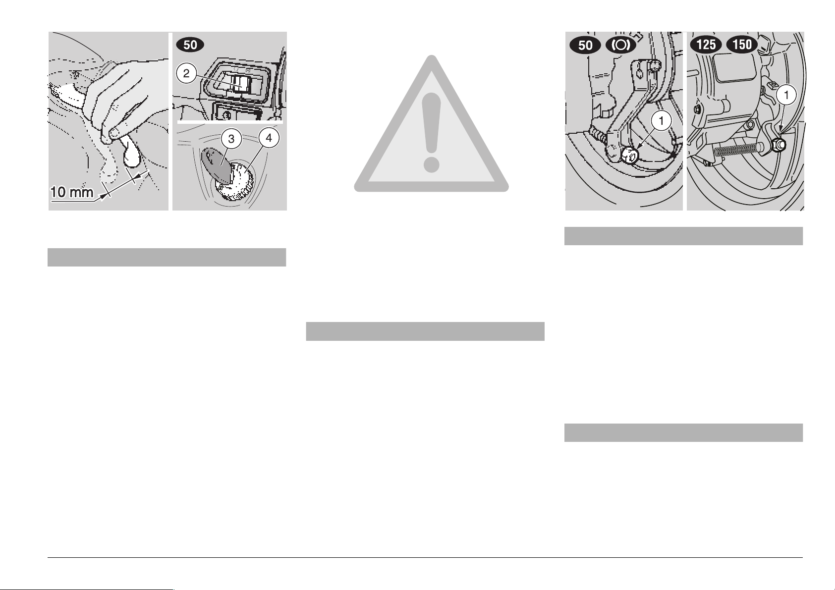
ADJUSTING THE BRAKE
◆
Measure the distance covered by the lever before the brake starts it braking action. The idle stroke at the end of the
brake lever must be about 10 mm.
To adjust the clearance, proceed as follows:
◆
Act on the adjuster (1).
◆
Put on the brake repeatedly and make
sure that the wheel turns freely after the
brake has been released.
◆
Check the braking efficiency.
aWARNING
If the adjuster (1) can be screwed up
completely, this means that the brake
shoes are worn out.
In this case, see p. 51 (CHECKING THE
SHOE WEAR).
NOTE The heating of the brake shoes
caused by the braking action may modify
the clearance between the friction material
and the drum. For this reason, it is advisable to check the clearance even with the
shoes at operating temperature.
◆
Carry out a trial run operating the rear
brake two or three times.
aWARNING
Carry out this check with the engine at
rest.
◆
Stop the vehicle, see p. 41 (STOPPING).
◆
. Move the engine stop switch (2) to
position “
quired).
◆
Rotate the key (3) and move the ignition
switch (4) to position “
◆
Position the vehicle on the centrestand.
◆
Make sure that the wheel turns freely.
If necessary:
m” (for the countries where re-
m”.
aWARNING
When the engine is hot, be careful not
to burn yourself while carrying out the
following operations.
◆
Loosen the adjuster (1), making sure that
the wheel turns freely.
use and maintenance SR 50 - SR 125 - SR 150
29
Page 30
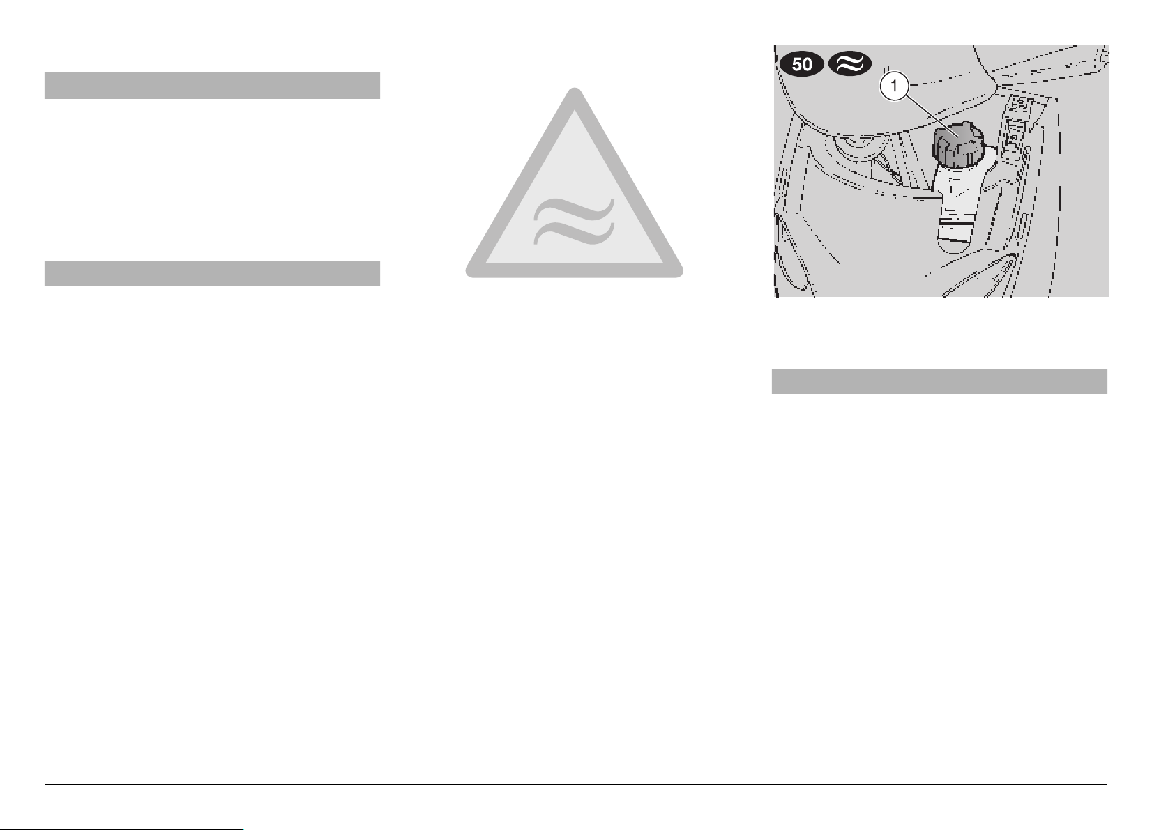
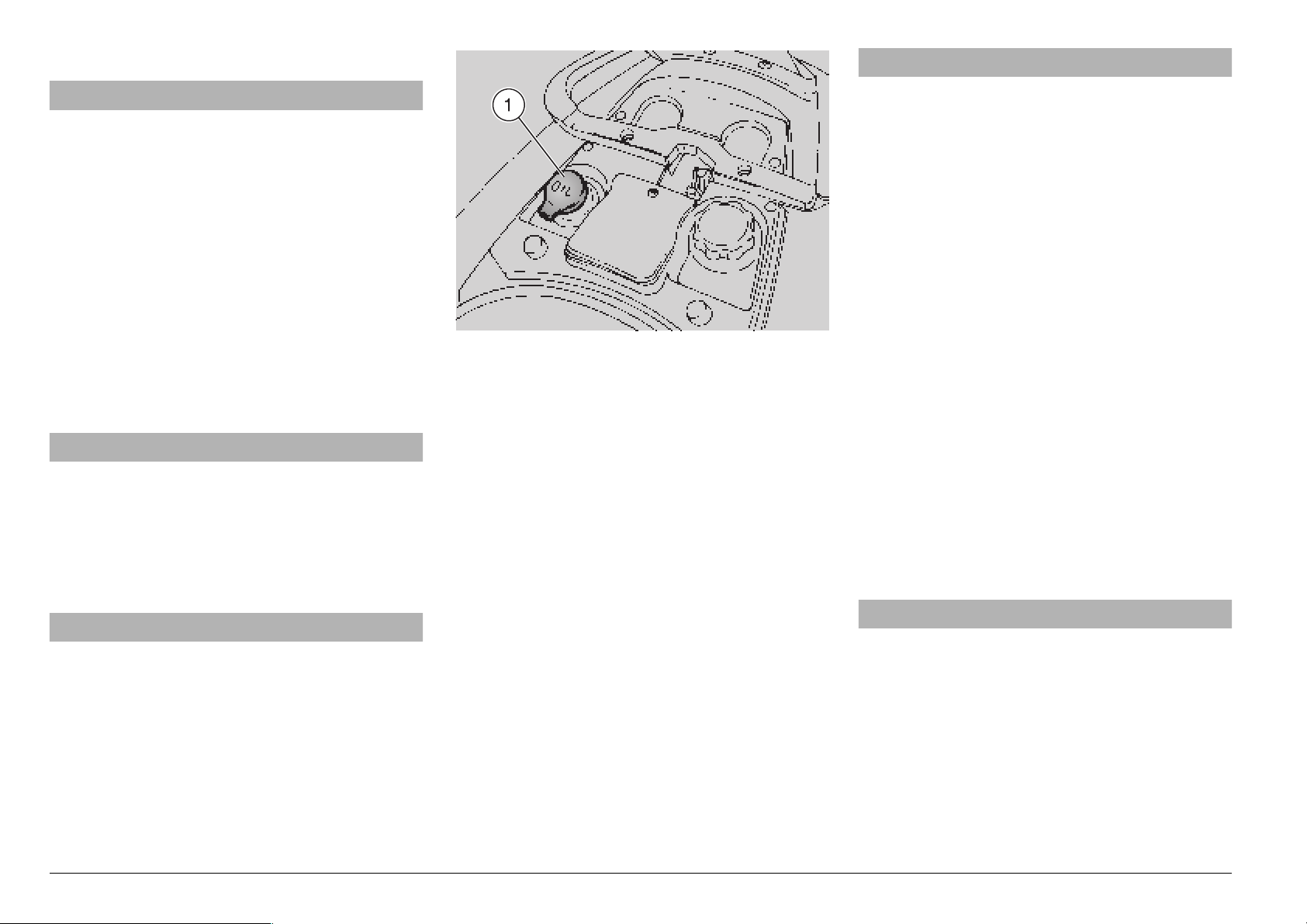
#//,!.4
.
1
aCAUTION
Do not use the vehicle if the coolant is
below the minimum prescribed level
“MIN”.
Check the coolant level every 2000 km
(1250 mi) and after long trips; have the
coolant changed by an aprilia Official
Dealer every 2 years.
aWARNING
The coolant is noxious: do not swallow
it; if the coolant gets in contact with the
skin or the eyes, it can cause serious irritations.
If the coolant gets in contact with your
skin or eyes, rinse with plenty of water
and consult a doctor. If it is swallowed,
induce vomit, rinse mouth and throat
with plenty of water and consult a doctor without delay.
DO NOT DISPOSE OF THE FLUID IN
THE ENVIRONMENT.
KEEP AWAY FROM CHILDREN.
Be careful not to spill the coolant on the
red-hot parts of the engine: it may catch
fire and send out invisible flames.
In case maintenance operations are to
be performed, it is advisable to use latex gloves.
The coolant is made up of 50% water and
50% antifreeze.
This mixture is ideal for most running temperatures and ensures good protection
against corrosion.
It is advisable to keep the same mixture
also in the hot season, since in this way
losses due to evaporation are reduced and
it is not necessary to top up very frequently.
The mineral salt deposits left in the radiator
by evaporated water are thus reduced and
the efficiency of the cooling system remains unchanged.
If the outdoor temperature is below 0°C,
check the cooling circuit frequently and if
necessary increase the antifreeze concentration (up to maximum 60%).
For the cooling solution use distilled water,
in order not to damage the engine.
aWARNING
Do not remove the expansion tank cap
(1) when the engine is hot, since the
coolant is under pressure and its temperature is high.
If it gets in contact with the skin or with
clothes it may cause severe burns
and/or damage.
Have the coolant changed by an APRILIA
Official Dealer.
use and maintenance SR 50 - SR 125 - SR 150
30
Page 31

CHECKING AND TOPPING UP
.
1
aWARNING
Check the coolant level and top up the
expansion tank with cold engine.
◆
Stop the engine and wait until it has
cooled down.
NOTE Position the vehicle on firm and
flat ground.
◆
Remove the front cover, see p. 53 (REMOVING THE FRONT COVER).
◆
Make sure that the level of the fluid contained in the expansion tank (2) is included between the “MIN” and “MAX” marks.
MIN = minimum level.
MAX= maximum level.
If not, proceed as follows:
◆
Loosen the filling cap (1) without removing it (give it half turn anticlockwise).
◆
Wait a few seconds in order to release
any residual pressure.
◆
Unscrew and remove the cap (1).
aWARNING
The coolant is noxious: do not swallow
it; if the coolant gets in contact with the
skin or the eyes, it can cause serious irritations.
Do not use your fingers or any other object to check if there is enough coolant.
aCAUTION
While topping up, never exceed the
“MAX” level, otherwise the fluid will
flow out of the tank while the engine is
running.
◆
Top up with coolant, p. 84 (
BRICANT CHART) until reaching approx. the “MAX” notch
◆
Put back the filling cap (1).
.
x LU-
aCAUTION
In case of excessive consumption of
coolant and in case the tank remains
empty, make sure that there are no
leaks in the circuit.
Have it repaired by an APRILIA Official
Dealer.
◆
Put back the front cover, see p. 53 (REMOVING THE FRONT COVER).
use and maintenance SR 50 - SR 125 - SR 150
31
Page 32

Some types of tyres homologated for
this vehicle are provided with wear indicators.
There are several kinds of wear indicators.
For more information on how to check
the wear, contact your Dealer.
Visually check if the tyres are worn and
in this case have them changed.
If the tyres are old, even if not completely worn out, they may become hard and
may not ensure good road holding.
In this case, have the tyres changed.
492%3
This vehicle is provided with tubeless tyres.
aWARNING
Periodically check the tyre inflation
pressure at room temperature, see p. 79
(TECHNICAL DATA).
If the tyres are hot, the measurement is
not correct.
Carry out the measurement especially
before and after long rides.
If the inflation pressure is too high, the
ground unevenness cannot be dampened and is therefore transmitted to the
handlebar, thus compromising the driving comfort and reducing road holding
during turns.
If, on the contrary, the inflation pressure
is too low, the tyre sides (1) are under
greater stress and the tyre itself may
slip on the rim or it may become loose,
with consequent loss of control of the
vehicle.
In case of sudden braking the tyres
could even get out of the rims. Further,
the vehicle could skid while turning.
Check the surface and the wear of the
tyres, since tyres in bad conditions can
impair both the grip and the controllability of the vehicle.
Change the tyre when it is worn out or
in case of puncture on the tread side, if
the puncture is larger than 5 mm.
After repairing a tyre, have the wheels
balanced.
Use only tyres in the size suggested by
APRILIA, see p. 79 (TECHNICAL DATA).
Do not install tyres with air tube on rims
for tubeless tyres and viceversa.
use and maintenance SR 50 - SR 125 - SR 150
32
Page 33

Make sure that the tyres always have
their valve sealing (2) caps on, to prevent them from suddenly going flat.
Change, repair, maintenance and balancing operations are very important
and should be carried out by qualified
technicians with appropriate tools.
For this reason, it is advisable to have
the above mentioned operations carried
out by an APRILIA Official Dealer or by a
qualified tyre repairer.
If the tyres are new, they may still be
covered with a slippery film: drive carefully for the first miles. Do not oil the
tyres with unsuitable fluids.
MINIMUM TREAD DEPTH LIMIT (3)
front: ........................... 1.5 mm (3 mm
rear: ............................ 1.5 mm (3 mm
-
-
!54/-!4)#
.
,)'(437)4#().'6%23)/.
The vehicles provided with the Automatic
Switch-on Device can be immediately recognized, since the lights come automatically on as soon as the engine is started.
For this reason the light switch has been
replaced with a dimmer switch “
The lights can be switched off only by stopping the engine.
◆
Before starting the vehicle, make sure
that the dimmer switch is in position “
(front low beam).
+
,)'(437)4#().'6%23)/.
The vehicles provided with the Automatic
Switch-on Device can be immediately rec-
)
ognized, since the lights come automatical-
)
ly on as soon as the engine is started.
For this reason the light switch has been
replaced with a dimmer switch “
The lights can be switched off only by turn-
ing the ignition switch to position “
◆
Before starting the vehicle, make sure
that the dimmer switch is in position “
(front low beam).
!54/-!4)#
b - a”.
b - a”.
_
b”
_
m”.
b”
use and maintenance SR 50 - SR 125 - SR 150
33
Page 34

#!4!,94)#3),%.#%2
2
aWARNING
Avoid parking the vehicle catalytic version near dry brush wood or in places
easily accessible to children, as the catalytic silencer becomes extremely hot
during use; be very careful and avoid
any kind of contact before it has completely cooled down.
The catalytic vehicle is fitted with a silencer
with metal catalytic converter of the “platinum-rhodium bivalent” type.
This device provides for the oxidation of
the CO (carbon monoxide) and of the HC
(unburned hydrocarbons) contained in the
exhaust gases, changing them into carbon
dioxide and steam, respectively.
Due to the catalytic reaction, the high temperature reached by the exhaust gases
makes for the burning of the oil particles,
thus keeping the silencer clean and eliminating the exhaust fumes.
To have the catalytic converter function
correctly and for long and to reduce possible problems regarding the soiling of the
thermal unit and of the exhaust, it is necessary to avoid covering long distances with
the engine running at constantly low rpm.
It is sufficient to alternate these periods
with periods in which the engine runs at relatively high rpm, even if only for a few seconds, but rather frequently.
What has been stated above assumes particular importance for the cold starting of
the engine: in this case, in order to reach a
rpm regime sufficient to enable the “priming” of the catalytic reaction, just make
sure that the temperature of the thermal
unit has reached at least 50°C, which generally occurs a few seconds after starting
the engine.
aCAUTION
Do not use leaded petrol, since it causes the destruction of the catalytic converter.
%8(!5343),%.#%2
aWARNING
Tampering with the noise control system is prohibited.
Owners are warned that the law may prohibit:
– the removal or rendering inoperative by
any person, other than for purposes of
maintenance, repair or replacement, of
any device or element of design incorporated into any new vehicle – for the purpose of noise control – prior to its sale or
delivery to the ultimate purchaser or
while it is in use; and
– the use of the vehicle after such device
or element of design has been removed
or rendered inoperative by any person.
Check the exhaust silencer and the silencer pipes, making sure that there are neither
signs of rust, nor holes and that the exhaust system works effectively.
If the noise produced by the exhaust system increases, immediately contact your
aprilia Official Dealer.
use and maintenance SR 50 - SR 125 - SR 150
34
Page 35

).3425#4)/.3&/253%
aWARNING
Before departure, always carry out a
preliminary checking of the vehicle, to
make sure that it functions correctly
and safely, see the following table PRELIMINARY CHECKING OPERATIONS.
The non-performance of these checking
operations can cause severe personal
injuries or damages to the vehicle.
Do not hesitate to consult your APRILIA
Official Dealer in case there is something you do not understand about the
functioning of some controls or in case
you suspect or discover some irregularities.
It does not take long to carry out a
check-up and this operation ensures
you much more safety.
02%,)-).!29#(%#+).'/0%2!4)/.3
Component Check Page
Disc brakes Check the functioning, the fluid level and make sure
there are no leaks.
Check the wear of the pads. Top up, if necessary.
Rear drum brake
3
Accelerator Make sure that it works smoothly and that it is possible to
2 stroke oil Check and/or top up, if necessary. 26
Wheel / tyres Check the tyre surface, the inflation pressure, wear and
Brake levers Make sure that they work smoothly.
Steering Make sure that the steering rotates smoothly, without any
Centre stand Make sure that they work smoothly and that the spring
Fastening elements Make sure that the fastening elements are not loose.
Fuel tank Check the fuel level and top up, if necessary.
Coolant
1
Engine stop switch
n - m) (in the
(
countries where
required)
Lights, warning
lights, horn and
electric devices
Check the functioning, the idle stroke and the control
lever conditions. If the clearance is not correct, adjust it
open and close it completely, in all steering positions.
If necessary, adjust and/or lubricate it.
tear and any damage.
If necessary, lubricate the articulations.
clearance or slackening.
tension brings it back to its normal position.
If necessary, lubricate joints and hinges.
If necessary, adjust or tighten them.
Make sure there are no leaks or occlusions in the circuit.
The coolant level in the expansion tank must be included
between the
Top up, if necessary.
Make sure that it functions correctly.
Check the proper functioning of all the devices.
Change the bulbs or intervene in case of failure. 65 – 75
“MIN” and “MAX” markings.
27, 28, 51
.
27, 28, 29
29, 51
32 ,33
30, 31
63
52
61
—
25
19
use and maintenance SR 50 - SR 125 - SR 150
35
Page 36

34!24).'
aWARNING
Exhaust gases contain carbon monoxide,
which is extremely noxious if inhaled.
Avoid starting the vehicle in closed or
badly-ventilated rooms.
The non-observance of this warning
may cause loss of consciousness or
even lead to death by asphyxia.
Do not get on the vehicle for the starting.
ELECTRIC STARTING
◆
Position the vehicle on the centre stand.
◆
Make sure that the light switch (1) is in
position“
◆
Make sure that the dimmer switch (2) is
in position “
◆
◆
Make sure that the dimmer switch (3)
_
is in position “
Rotate the key (4) and move the ignition
switch to position “
”.
•
b”.
b”.
n”.
◆
◆
Move the engine stop switch (5) to
.
position “
quired).
Lock at least one wheel, by pulling a
brake lever (6).
If this operation is not carried out, the
start relay receives no current and therefore the engine does not start.
n”, (in the countries where re-
NOTE After a long period of inactivity,
carry out the operations described at p. 37
(STARTING AFTER A LONG PERIOD OF
INACTIVITY).
NOTE To avoid the excessive wear of
the battery, do not keep the start push but-
r” pressed for more than five sec-
ton “
onds. If the engine does not start within this
lapse of time, wait ten seconds and press
the start push button “
◆
Press the start push button “r” (7) without accelerating, then release it as soon
as the engine starts.
r” again.
aCAUTION
When the start push button “r” is
pressed, the 2 stroke oil reserve warning
light “
With the engine in running condition,
when the start push button “
leased, the 2 stroke oil reserve warning
light “
occur, top up the 2 stroke oil tank, see
p. 26 (2 STROKE OIL).
Avoid pressing the start push button
“
since you may damage the starter.
NOTE
(in particular at very low temperatures),
wait 15-20 seconds without accelerating, in
order to allow the engine to warm up.
◆
To leave, see p. 38 (DEPARTURE AND
DRIVE).
j” comes on.
r” is re-
j” must go out; if this does not
r” (7) when the engine is running,
+
Do not accelerate and pull the brake levers at the same time until you move off.
After starting the engine
use and maintenance SR 50 - SR 125 - SR 150
36
Page 37

KICK START
◆
Position the vehicle on the centre stand.
◆
Move to the left side of the vehicle.
◆
Make sure that the light switch (1) is in
position“
◆
Make sure that the dimmer switch (2) is
in position “
◆
◆
◆
◆
◆
Make sure that the dimmer switch (3)
_
is in position “
Rotate the key (4) and move the ignition
switch to position “
Move the engine stop switch (5) to
.
position “
quired).
To avoid losing control of the vehicle during the starting, lock both wheels by
putting on the brake levers (6).
+
wards.
”.
•
b”.
b”.
n”.
n”, (in the countries where re-
Rotate the start pedal (8) out-
aCAUTION
Do not push down the kick starter with
the engine on.
◆
Push down the kick starter (8) with your
right foot, releasing it immediately.
If necessary, repeat the operation until
the engine starts.
◆
+
its original position.
STARTING WITH FLOODED ENGINE
If the starting is not carried out properly or if
there is too much fuel in the intake ducts
and in the carburettor, the engine may get
flooded.
To clean a flooded engine:
◆
Press the start push button “r” (7) for a
few seconds (letting the engine spin
over) with completely open throttle (9)
(Pos. A).
STARTING WITH COLD ENGINE
When the room temperature is low (near or
below 0°C), it may be difficult to start the
engine at the first attempt.
In this case:
◆
.
downwards.
◆
Press the start push button “r” (7) and
at the same time rotate the throttle grip
(9) moderately.
Rotate the start pedal (8) back to
Rotate the cold start lever “e” (10)
If the engine starts.
◆
Release the throttle grip (9).
◆
If the idling is unstable, twist the throttle
grip (9) slightly and frequently.
To leave, see p. 38 (DEPARTURE AND
DRIVE).
If the engine does not start.
Wait a few seconds and repeat the STARTING WITH COLD ENGINE procedure.
◆
If necessary, remove the spark plug, see
p. 64 (SPARK PLUG) and make sure
that it is not wet.
◆
If the spark plug is wet, clean and dry it.
Before reinstalling it:
NOTE Put a clean cloth on the cylinder,
near the spark plug seat, in order to protect
it from oil sprays.
◆
Press the start push button “r” (7) and
let the starter run for about five seconds
without accelerating.
STARTING AFTER A LONG PERIOD
OF INACTIVITY
After a long period of inactivity, if the start
is not immediate, this may be due to the
fact that the fuel circuit is partially empty.
In this case:
◆
Press the start push button “r” (7) for
about five seconds, in order to ensure
the filling of the float chamber.
use and maintenance SR 50 - SR 125 - SR 150
37
Page 38

$%0!2452%!.$$2)6%
NOTE Before departure, carefully read
the “safe drive” chapter, see p. 5 (SAFE
DRIVE).
aWARNING
Any mention to the use of the vehicle
with passenger is to be intended as referred only to the countries where this
is allowed.
While riding, keep your hands on the
grips and your feet on the footrests.
NEVER RIDE IN ANY POSITION OTHER
THAN THOSE INDICATED.
If you drive with a passenger, instruct
him/her so that he / she does not create
problems during manouvres.
Before leaving, make sure that the
stand/stands is / are completely up.
To leave:
◆
Release the throttle grip (Pos. A), put on
the rear brake, then move the vehicle
down the stand.
◆
Get on the vehicle, keeping at least one
foot on the ground in order not to lose
balance.
◆
Adjust the inclination of the rear-view
mirrors correctly.
aWARNING
With the vehicle at rest, try to get acquainted with the use of the rear-view
mirrors.
◆
To leave, release the brake lever and accelerate by gently rotating the throttle
grip (Pos. B); the vehicle will start moving.
◆
Once the engine has warmed up,
.
see p. 17 (
cator
upwards.
1), rotate the cold start lever “e”
Coolant temperature indi-
.
aCAUTION
Never leave abruptly with cold engine.
To reduce the emission of polluting
substances and the consumption of fuel, warm the engine up by proceeding at
low speed for the first miles.
aWARNING
Avoid opening and closing the throttle
repeatedly and continuously, so that
you do not accidentally lose control of
the vehicle.
use and maintenance SR 50 - SR 125 - SR 150
38
Page 39

aWARNING
If you have to brake, close the throttle
and put on both brakes in order to obtain uniform deceleration, properly exerting pressure on the braking parts.
By putting on the front brake only or the
rear brake only, you reduce the braking
force considerably, thus running the
risk of locking one wheel and consequently losing grip.
If you stop uphill, decelerate completely
and use the brakes only to keep the vehicle steady.
The use of the engine to keep the vehicle at a halt may cause the overheating
of the speed variator.
Before beginning to turn, slow down or
brake driving at moderate and constant
speed or accelerating slightly; avoid
braking at the last moment: it would be
very easy to skid.
If the brakes are operated continuously
on downhill stretches, the friction material may overheat, thus reducing the
braking efficiency.
Exploit the engine compression by
putting on both brakes intermittently.
Never drive downhill with the engine
off!
aWARNING
In case of wet road or scarce wheel grip
(snow, ice, mud, etc.), drive slowly,
avoiding sudden brakings or manoeuvres that could make you lose grip and
fall down.
Pay the utmost attention to any obstacle or variation of the road surface.
Uneven roads, rails, manhole covers,
indications painted on the road surface,
building site metal plates become rather
slippery by rain. For this reason all
these obstacles have to be carefully
avoided, driving smoothly and bending
the vehicle as little as possible.
Always use the direction indicators in
time when you intend to change lane or
direction, avoiding sharp and dangerous movements.
Switch off the direction indicators as
soon as you have changed direction.
Be extremely careful when you overtake
other vehicles or are overtaken.
In case of rain, the water cloud created
by big vehicles reduces visibility; the
air shift may make you lose control of
the vehicle.
aWARNING
If the 2 stroke oil reserve warning light
“
j” comes on during the normal func-
tioning of the engine, this means that
the 2 stroke oil reserve is being used; in
this case, top up the 2 stroke oil tank,
see p. 26 (2 STROKE OIL).
aCAUTION
. 1 If the pointer of the coolant tem-
perature indicator “
area, stop the engine and check the
coolant level, see p. 30 (
).
1
h” reaches the red
COOLANT
.
use and maintenance SR 50 - SR 125 - SR 150
39
Page 40

25..).').
.
+
25..).').
aWARNING
After the first 500 km (312 mi), carry out
the checking operations indicated in the
column “After running-in” of the REGULAR SERVICE INTERVALS CHART, see
p. 44, in order to avoid hurting yourself
or other people and/or damaging the vehicle.
The running-in of the engine is primary to
ensure its correct functioning and its correct
functioning.
If possible, drive on hilly roads and/or roads
with many bends, so that the engine, the
suspensions and the brakes undergo a
more effective running-in.
For the first 500 km (312 mi), keep to the
following indications:
◆
0-100 km (0-62 mi)
During the first 100 km (62 mi) put on
the brakes with caution, avoiding sharp
and prolonged brakings.
This ensures a correct bedding-in of the
pads on the brake disc.
◆
0-300 km (0-187 mi)
Do not keep the throttle grip open more
than one half for long stretches.
◆
300-500 km (187-312 mi)
Do not keep the throttle grip open more
than three-fourths for long stretches.
aWARNING
After the first 1000 km (625 mi), carry
out the checking operations indicated in
the column “after running-in” of the
REGULAR SERVICE INTERVALS
CHART, see p. 46, in order to avoid hurting yourself or other people and/or damaging the vehicle.
The running-in of the engine is primary to
ensure its correct functioning and its correct
functioning.
If possible, drive on hilly roads and/or roads
with many bends, so that the engine, the
suspensions and the brakes undergo a
more effective running-in.
Keep to the following indications:
◆
Do not open the throttle completely if the
speed is low, both during and after the
running-in.
◆
0-100 km (0-62 mi)
During the first 100 km (62 mi) put on
the brakes with caution, avoiding sharp
and prolonged brakings.
This ensures a correct bedding-in of the
pads on the brake disc.
◆
0-1000 km (0-625 mi)
During the first 1000 km (625 mi), do not
exceed the 80% of the maximum allowed
speed.
◆
Avoid driving at constant speed for long
distances.
◆
After the first 1000 km (625 mi), progressively increase the speed until reaching
the highest performance levels.
use and maintenance SR 50 - SR 125 - SR 150
40
Page 41

34/00).'
aWARNING
If possible, avoid stopping abruptly,
slowing down suddenly and braking at
the last moment.
◆
Release the throttle grip (Pos. A) and
gradually put on the brakes to stop the
vehicle.
◆
In case of a brief stop, keep at least one
brake on.
0!2+).'
aWARNING
Park the vehicle on firm and flat ground,
to prevent it from falling down.
Neither lean the vehicle against walls,
nor lay it on the ground.
Make sure that the vehicle and especially its red-hot parts do not represent a
danger for persons and children.
Do not leave the vehicle unattended
when the engine is on or the key is inserted into the ignition switch.
Do not sit on the vehicle when the stand
is down.
◆
Stop the vehicle, see beside (STOPPING).
◆
Move the engine stop switch (1) to position “
quired).
m” (for the countries where re-
aCAUTION
With stopped engine and ignition
switch in position “
run down.
◆
Rotate the key (2) and move the ignition
switch (3) to position “
◆
Position the vehicle on the stand, see
p. 42 (POSITIONING THE VEHICLE ON
THE STAND).
n”, the battery may
m”.
aCAUTION
It is not necessary to close the fuel tap
when the engine is off, since it is
equipped with an automatic closing
system.
aCAUTION
Never leave the key in the ignition
switch.
◆
Lock the steering, see p. 22 (STEERING
LOCK) and extract the key (2).
use and maintenance SR 50 - SR 125 - SR 150
41
Page 42

0/3)4)/.).'4(%6%()#,%
/.4(%34!.$
Carefully read p. 41 (PARKING).
CENTRE STAND
◆
Grasp the left handgrip and the left rear
grab rail (1).
◆
Push down the stand lever (2).
35''%34)/.3
4/02%6%.44(%&4
NEVER leave the ignition key inserted and
always use the steering lock.
Park the vehicle in a safe place, possibly in
a garage or a protected place.
If possible, use the appropriate aprilia
“Body-Guard” armored cable
ditional anti-theft device.
, or an ad-
&
Write down your personal data and telephone number in the space provided in this
page, to facilitate the identification of the
owner in case of finding after theft.
SURNAME: ................................................
NAME:........................................................
ADDRESS:.................................................
use and maintenance SR 50 - SR 125 - SR 150
42
Make sure that all documents are in order
and the road tax has been paid.
...................................................................
TELEPHONE NO.:.....................................
NOTE Very often stolen vehicles are
identified thanks to the data written on the
use/maintenance manual.
Page 43

-!).4%.!.#%
aWARNING
Risk of fire.
Keep fuel and other flammable substances away from the electrical components.
Before beginning any maintenance operation or any inspection of the vehicle,
stop the engine, extract the key from
the ignition block, wait until the engine
and the exhaust system have cooled
down and if possible lift the vehicle by
means of the proper equipment, on firm
and flat ground.
Before proceeding, make sure that the
room in which you are working is properly ventilated.
Keep away from the red-hot parts of the
engine and of the exhaust system, in order to avoid burns.
Do not hold any mechanical piece or
other parts of the vehicle with your
mouth: the components are not edible
and some of them are noxious or even
toxic.
aCAUTION
If not expressly indicated otherwise, for
the reassembly of the units repeat the
disassembly operations in reverse order.
In case any maintenance operation has
to be carried out, it is advisable to use
latex gloves.
Normally, the routine maintenance operations can be performed by the user; however, in some cases the use of specific
tools and technical expertise may be required.
If you need assistance or technical advice,
consult your aprilia Official Dealer, who
can ensure you prompt and accurate servicing.
Ask your aprilia Official Dealer to test the
vehicle on the road after a repair or periodic maintenance operation.
In any case, personally carry out the “Preliminary checking operations” after any
maintenance operation, see p. 35 (PRELIMINARY CHECKING OPERATIONS).
use and maintenance SR 50 - SR 125 - SR 150
43
Page 44

2%'5,!22%'5,!23%26)#%
).4%26!,3#(!24x
OPERATIONS TO BE CARRIED OUT BY
THE APRILIA Official Dealer (WHICH
CAN BE CARRIED OUT EVEN BY THE
USER).
Component
Battery - Terminal fastening Electrolyte level
After running-in
[500 km (312 mi)]
–
Every 4000 km
(2500 mi) or 12
months
Every 8000 km
(5000 mi) or 24
months
Spark plug –
Key
= check and clean, adjust, lubricate or
change, if necessary;
= clean;
= change;
= adjust.
NOTE Carry out the maintenance opera-
tions more frequently if you use the vehicle
in rainy and dusty areas or on uneven
ground.
Carburettor - idling –
Air cleaner –
Accelerator operation –
Brake locking operation –
Light system –
Stop light switches – –
Brake fluid – –
2 stroke oil every 500 km (312 mi):
Headlight beam direction - operation – –
Wheels/tyres and inflation pressure every month:
Front and rear brake pad wear every 2000 km (1250 mi):
use and maintenance SR 50 - SR 125 - SR 150
44
Page 45

OPERATIONS TO BE CARRIED OUT BY
THE APRILIA Official Dealer.
Key
= check and clean, adjust, lubricate or
change, if necessary;
= clean;
= change;
= adjust.
NOTE Carry out the maintenance opera-
tions more frequently if you use the vehicle
in rainy and dusty areas or on uneven
ground.
After running-in
Component
Rear shock absorber – –
Transmission cables and controls
Variator belt every 6000 km:
Steering tube bearings and steering
slack
Wheel bearings –
Brake discs
Piston rings every 12000 km (7500 mi):
Accelerator operation - Mixer
General running of the vehicle
Braking systems/brake discs
Cylinder cooling system every 20000 km (12500 mi):
Rear brake cam pin greasing
Brake fluid every 2 years:
Coolant
Fork oil and oil seal every 12000 km (7500 mi):
Transmission oil
Rear pulley pins every 12000 km (7500 mi):
Movable/fixed front pulley every 6000 km (3750 mi):
Variator front pins and guides every 6000 km (3750 mi):
Wheels/tyres and inflation pressure
Nut, bolt, screw tightening
Front suspension
2 stroke oil reserve warning light
Fuel pipe every 4000 km (2500 mi):
Braking system pipe –
Mixer oil pipe
Clutch wear – –
Rear brake shoe wear
q
t
t
[500 km (312 mi)]
–
every 2000 km (1250 mi): / every 2 years:
––
Every 4000 km
(2500 mi) or 12
months
(outside cleaning)
/ every 4 years:
Every 8000 km
(5000 mi) or 24
every 12000 km
every 4 years:
every 2 years:
months
–
–
–
–
–
–
–
–
(7500 mi) or 2
years:
–
–
–
–
use and maintenance SR 50 - SR 125 - SR 150
45
Page 46

2%'5,!22%'5,!23%26)#%
).4%26!,3#(!24z{
OPERATIONS TO BE CARRIED OUT BY
THE APRILIA Official Dealer (WHICH
CAN BE CARRIED OUT EVEN BY THE
USER).
Component
After running-
in [1000 km
(625 mi)]
Every 4000
km (2500 mi)
or 12 months
Every 8000
km (5000 mi)
or 24 months
Battery - Terminal fastening –
Spark plug
Key
= check and clean, adjust, lubricate or
change, if necessary;
= clean;
= change;
= adjust.
NOTE Carry out the maintenance opera-
tions more frequently if you use the vehicle
in rainy and dusty areas or on uneven
ground.
Carburettor - idling –
Air cleaner –
Accelerator operation –
Brake locking operation –
Light system –
Stop light switches – –
Brake fluid – –
2 stroke oil every 500 km (312 mi):
Headlight beam direction - operation – –
Wheels/tyres - inflation pressure every month:
Brake pad wear every 2000 km (1250 mi):
use and maintenance SR 50 - SR 125 - SR 150
46
Page 47

OPERATIONS TO BE CARRIED OUT BY
THE APRILIA Official Dealer.
Key
= check and clean, adjust, lubricate or
change, if necessary;
= clean;
= change;
= adjust.
NOTE Carry out the maintenance opera-
tions more frequently if you use the vehicle
in rainy and dusty areas or on uneven
ground.
Component
Rear shock absorber – –
Transmission cables and controls
Cylinder/Piston every 12000 km (7500 mi):
Mixer belt every 30000 km (18750 mi):
Speed change gear belt and roller
shoes
Steering tube bearings and steering
slack
Wheel bearings –
Brake discs
Piston rings every 12000 km (7500 mi):
General running of the vehicle
Braking systems
Cylinder cooling system every 20000 km (12500 mi):
Gas cable splitter greasing every 12000 km (7500 mi):
Brake fluid every 2 years:
Mixer/accelerator operation
Fork oil and oil seal every 12000 km (7500 mi):
Transmission oil
Wheels/tyres and inflation pressure
Nut, bolt, screw tightening
2 stroke oil reserve warning light
Fuel pipe –
Braking system pipe –
Mixer oil pipe
Clutch wear – –
After running-in
[1000 km (625 mi)]
every 12000 km (7500 mi):
Every 4000 km
(2500 mi) or 12
months
––
Every 8000 km
(5000 mi) or 24
(outside cleaning)
every 12000 km
every 4 years:
every 4 years:
every 4 years:
months
–
–
–
–
–
–
–
(7500 mi):
–
–
Rear brake shoe wear
t
every 2000 km (1250 mi):
use and maintenance SR 50 - SR 125 - SR 150
47
Page 48

)$%.4)&)#!4)/.$!4!
+
ENGINE NUMBER
FRAME NUMBER
It is a good rule to write down the frame
and engine numbers in the space provided
in this manual.
The frame number can be used for the
purchase of spare parts.
NOTE The engine number is stamped
on the rear side, near the rear brake adjuster.
ENGINE NUMBER
.
The engine number is stamped on the lower support of the rear shock absorber.
Engine no.
The engine number is stamped on the rear
side, near the rear brake adjuster.
Engine no.
The frame number is stamped on the central tube of the frame. To be able to read it,
it is necessary to remove the cover (1).
NOTE The cover (1) can be inserted in
one direction only. The part provided with
the tang (2) is the lower part.
Frame no.
use and maintenance SR 50 - SR 125 - SR 150
48
Page 49

!)2#,%!.%2
.
aWARNING
Do not use petrol or inflammable solvents to wash the air cleaner, in order to
avoid fires or explosions.
Carefully read p. 43 (MAINTENANCE).
Check the conditions of the air cleaner and
clean it monthly or every 4000 km (2500
mi), depending on the conditions in which
the vehicle is used.
If the vehicle is used on dusty or wet roads,
the cleaning operations and any replacement should be carried out more frequently.
To clean the filtering element it is necessary to remove the whole filter casing from
the vehicle.
REMOVAL
◆
Remove the lower shield cover, see
p. 59 (
REMOVING THE LOWER
.
SHIELD COVER).
◆
Remove the left inspection cover, see
p. 55 (REMOVING THE RIGHT AND
LEFT INSPECTION COVERS).
◆
Unscrew and remove the screw (1), taking the washer and the breather pipe ring
(2).
◆
Unscrew and remove the screw (3) with
the relevant washer.
◆
Loosen the screw (4) of the air manifold
clamp.
◆
Grasp the air manifold in correspondence with the clamp and pull it, thus removing the whole air cleaner casing.
CLEANING THE AIR FILTER
◆
Unscrew the three screws (5).
◆
Remove the filter case cover (6) and extract the filtering element.
◆
To clean the filtering element use clean,
non-inflammable solvents or solvents
with high volatility point, then let it dry
thoroughly.
◆
Apply a filter oil or a thick oil (SAE 80W-
90) on the whole surface of the filtering
element, then squeeze it to eliminate the
oil in excess.
NOTE The filter must be well impregnat-
ed, though not dripping.
use and maintenance SR 50 - SR 125 - SR 150
49
Page 50

+
!)2#,%!.%2
Carefully read p. 43 (MAINTENANCE).
Check the conditions of the air cleaner and
clean it monthly or every 4000 km (2500
mi), depending on the conditions in which
the vehicle is used.
If the vehicle is used on dusty or wet roads,
the cleaning operations and any replacement should be carried out more frequently.
To clean the filtering element it is necessary to remove it from the vehicle.
REMOVAL
◆
Position the vehicle on the centre stand.
◆
Unscrew and remove the two screws (1).
◆
Unscrew and remove the seven screws
(2).
◆
Remove the filter case cover (3).
◆
Remove the filtering element (4).
◆
Check:
– filtering element (4);
– filter case gasket (5);
and change them if necessary.
CLEANING
aWARNING
Do not use petrol or inflammable solvents to wash the filtering element, in
order to avoid fires or explosions.
◆
Wash the filtering element (4) with clean,
non-inflammable solvents or solvents
with high volatility point, then let it dry
thoroughly.
◆
Apply a filter oil on the whole surface of
the filtering element.
use and maintenance SR 50 - SR 125 - SR 150
50
Page 51

#(%#+).'
4(%"2!+%0!$7%!2
Carefully read p. 27 (BRAKE FLUID recommendations), p. 28 (DISC
BRAKES), p. 43 (MAINTENANCE).
.
Check the brake pad wear after the first
500 km (312 mi) and successively every
2000 km (1250 mi).
+
Check the brake pad wear after the first
1000 km (625 mi) and successively every
2000 km (1250 mi).
aWARNING
Check the wear of the brake pads especially before every trip.
To carry out a rapid checking of the wear of
the front pads, proceed as follows:
◆
Position the vehicle on the centre stand.
◆
Remove the brake caliper cover (1).
◆
Carry out a visual check between brake
disc and pads.
aWARNING
The excessive wear of the friction material would cause the contact of the pad
metal support with the disc, with consequent metallic noise and production of
sparks from the caliper; braking efficiency, safety and soundness of the
disc would thus be negatively affected.
◆
If the thickness of the friction material
(even of one pad only) has reduced to
about 1.5 mm, replace both pads.
aWARNING
Have the pads changed by your APRILIA
Official Dealer.
#(%#+).'4(%3(/%7%!2
Carefully read p. 29 (REAR DRUM
BRAKE) and p. 43 (MAINTENANCE).
.
Have the rear brake shoe wear checked by
an aprilia Official Dealer after the first 500
km (312 mi) and successively every 4000
km (2500 mi).
+
Have the rear brake shoe wear checked by
an aprilia Official Dealer after the first
1000 km (625 mi) and successively every
2000 km (1250 mi).
In any case:
The wear of the brake pads depends on
the use, on the kind of drive and on the
road. The wear will be greater when the vehicle is driven on dirty or wet roads.
aWARNING
If the adjuster (2) can be screwed completely, this means that the shoes are
worn; in this case, contact an APRILIA
Official Dealer.
use and maintenance SR 50 - SR 125 - SR 150
51
Page 52

#(%#+).'4(%34%%2).'
Carefully read p. 43 (MAINTENANCE).
Occasionally check the steering slack.
To check the steering it is necessary to:
◆
Position the vehicle on the centre stand.
NOTE
port, the base of which must measure 200
x 200 mm.
NOTE
support, the base of which must measure
200 x 200 mm.
◆
Place the support under the vehicle and
a spongy cloth between them, so that the
front wheel can move freely and the vehicle cannot fall down.
Prepare a 270 mm high sup-
.
+
Prepare a 210 mm high
aWARNING
Make sure that the vehicle is stable.
◆
Shake the fork in the direction of travel.
NOTE Do not shake the fork excesively,
otherwise you may take in consideration
the movement of the stand, thus observing
an incorrect slack.
Repeat the previous operation more than
once.
◆
If you find that there is a considerable
slack, contact your aprilia Official Dealer
to restore the optimal steering conditions.
#(%#+).'
4(%%.').%&5,#25-!8)3
Carefully read p. 43 (MAINTENANCE).
Periodically check the slack existing between the engine pin bushings.
To carry out this operation, proceed as follows:
◆
Position the vehicle on the centre stand.
◆
Shake the wheel transversally with respect to the riding direction.
◆
If any slack should be noticed, contact
your aprilia Official Dealer, to restore the
optimal operating conditions.
use and maintenance SR 50 - SR 125 - SR 150
52
Page 53

2%-/6).'4(%
#/6%23500/24%,%-%.4
Carefully read p. 43 (MAINTENANCE).
◆
Position the vehicle on the centre stand.
◆
Rotate the handlebar completely, unscrew and remove the screws (1).
◆
Remove the cover support element (2).
NOTE Upon reassembly, fit the tangs
correctly in the appropriate seats.
2%-/6).'4(%&2/.4#/6%2
Carefully read p. 43 (MAINTENANCE).
◆
Remove the cover support element (2),
see beside (REMOVING THE COVER
SUPPORT ELEMENT).
◆
Rotate the handlebar completely, unscrew and remove the screws (3), taking
the washers.
aCAUTION
Proceed with care.
Do not damage the tangs and/or their
seats.
Handle the plastic and painted components with care and avoid scraping or
damaging them.
◆
Remove the front cover (4), by pulling it
upwards.
NOTE Upon reassembly, correctly insert
the lower tang (5) and successively the
four side tangs (6) in their seats.
use and maintenance SR 50 - SR 125 - SR 150
53
Page 54

2%-/6).'4(%,/7%2
(!.$,%"!2#/6%2
Carefully read p. 43 (MAINTENANCE).
◆
Remove the cover support element, see
p. 53 (REMOVING THE COVER SUPPORT ELEMENT).
NOTE Support the front part of the fair-
ing (1), to prevent it from accidentally falling down.
◆
★ Unscrew and remove the two screws
(2).
aCAUTION
Handle the plastic or painted components with care and avoid scraping or
damaging them.
◆
Remove the front part of the fairing (1).
◆
★ Unscrew and remove the screw (3).
◆
★ Rotate the handlebar completely right-
wards, unscrew and remove the screw
(4) (with shorter diameter) and the
screws (5) (6) and (7).
NOTE Upon reassembly, fit the screws
(4) (with shorter diameter) in the relevant
seats.
◆
Rotate the handlebar in central position,
withdraw the lower handlebar cover (8)
from the front and remove it.
0!24)!,2%-/6!,/&4(%
500%2(!.$,%"!2#/6%2
Carefully read p. 43 (MAINTENANCE).
◆
Remove the rear-view mirrors, see p. 61
(REMOVING THE REAR-VIEW MIRRORS).
◆
Remove the lower handlebar cover, see
beside (REMOVING THE LOWER HANDLEBAR COVER).
◆
★ Disconnect the two electric terminals
(9).
aCAUTION
The upper handlebar cover (10) (complete with switches, instruments and indicators) remains connected with the
speedometer cable and with the electric
cables, which makes it impossible to remove it completely.
Proceed with care in order to avoid
damaging the components.
◆
Paying attention to the two switch connections (11), lift the upper handlebar
cover and rotate it forwards, then rest it
on the front shield.
NOTE Upon reassembly, when position-
ing the upper handlebar cover, pass the
electric terminal cables (9) behind and under the handlebar.
use and maintenance SR 50 - SR 125 - SR 150
54
Page 55

2%-/6).'4(%2)'(4!.$,%&4
).30%#4)/.#/6%23
Carefully read p. 43 (MAINTENANCE).
NOTE Handle the painted components
with care and avoid scraping or damaging
them.
◆
Position the vehicle on the centre stand.
◆
Remove the battery/tool kit compartment
cover (1), see p. 24 (BATTERY / TOOL
KIT COMPARTMENT).
◆
Remove the tool kit compartment (2).
◆
Unscrew and remove the two screws (3).
NOTE Carry out the following operations
on the side of the inspection cover to be removed.
◆
Unscrew and remove the screw (4) and
the screw (5) of the rear part of the fairing.
NOTE Upon reassembly, fit the screw
(5) (with shorter diameter) of the rear part
of the fairing in the relevant seat.
◆
Slightly raise the inspection cover (6), release it from the footrest and withdraw it
sidewards.
NOTE Upon reassembly, insert the rear
part of the inspection cover in the rear part
of the fairing, making the seat (7) coincide
with the end of the rear part of the fairing
(8).
NOTE In points (9) and (10) the left in-
spection cover must overlap the right
ispection cover.
If both inspection covers have been removed, reassemble first the right and then
the left cover.
use and maintenance SR 50 - SR 125 - SR 150
55
Page 56

).34!,,).'4(%2%!2
.
-5$'5!2$%84%.3)/.
Carefully read p. 43 (MAINTENANCE).
◆
Position the vehicle on the centre stand.
◆
Unscrew and remove the nuts (1).
◆
Remove the reflector (2).
AC%K-_
◆
Grasp the bulb socket (3), pull and take it
out of its seat.
◆
Remove the number plate light (4).
◆
Unscrew and remove the nut (5).
◆
Withdraw the screw (6).
◆
Position the rear mudguard extension (7)
inside the number plate holder support
(8).
◆
Position the reflector (2) and tighten the
relevant nuts (1).
AC%K-_
◆
Position the number plate light (4) and
tighten the relevant nuts.
◆
Insert the number plate light cable (3) in
the two couplings.
◆
Insert the screw (6) and tighten the relevant nut (5).
◆
Make sure that the rear mudguard extension (7) is positioned correctly.
+
2%-/6).'4(%.5-"%2
0,!4%3500/24
Carefully read p. 43 (MAINTENANCE).
◆
Position the vehicle on the centre stand.
◆
Unscrew and remove the number plate
fastening screws.
◆
Remove the number plate.
NOTE Pay attention to the position of the
two spacers (9), in order to be able to reinstall them correctly.
◆
Unscrew and remove the three screws
(10), taking the nuts.
◆
Take the number plate support (11) and
the two spacers (9).
use and maintenance SR 50 - SR 125 - SR 150
56
Page 57

+
).34!,,).'4(%2%!2
-5$'5!2$%84%.3)/.
Carefully read p. 43 (MAINTENANCE).
◆
Remove the number plate support, see
p. 56 (
+
REMOVING THE NUM-
BER PLATE SUPPORT).
◆
Grasp the bulb socket (1), pull and take it
out of its seat.
◆
Release the number plate light cable
from the two couplings (2).
◆
Unscrew and remove the two nuts (3).
◆
Remove the number plate light (4).
◆
Correctly position the rear mudguard extension (5) in its seat.
◆
Mark the three holes (6) with an indelible
felt-tip pen, as indicated in the figure.
◆
Remove the rear mudguard extension
(5).
◆
Using a cross-point screwdriver, press in
correspondence with the marks, in order
to obtain the seat.
aWARNING
Proceed with care. Keep your hands
away from the drilling axis.
◆
Drill in correspondence with the three
seats (holes with diameter 5).
◆
Position the rear mudguard extension (5)
correctly in its seat.
◆
Insert the three screws (7) and screw the
relevant nuts, without tightening them.
◆
Make sure that the rear mudguard extension (5) is positioned correctly.
◆
Tighten the three nuts.
◆
Position the number plate light (4) correctly on the mudguard extension seat.
◆
Screw and tighten the two nuts (3).
◆
Position the bulb socket (1) correctly in
its seat.
◆
Insert the number plate light cable (2) in
the two couplings.
◆
Put back the number plate support,see
p. 56 (
+
REMOVING THE NUM-
BER PLATE SUPPORT).
use and maintenance SR 50 - SR 125 - SR 150
57
Page 58

+
$)2%#4)/.).$)#!4/2
◆
Position the vehicle on the centre stand.
◆
Unscrew and remove the screw (1).
2%-/6).'4(%7(/,%
NOTE When removing the protection
screen, proceed with care, in order not to
break the cog.
◆
Remove the protection screen (2).
NOTE Upon reassembly, position the
protection screen correctly in its seat.
Tighten the screw (1) moderately and with
care, in order not to damage the protection
screen.
aCAUTION
Handle with care.
Do not force the electric cables.
◆
Extract the bulb socket (3) as much as
necessary to disconnect its two electric
terminals (4).
NOTE Upon reassembly, make the bulb
socket opening coincide with the seat of
the screw (1).
◆
Unscrew the screw (5) and take the relevant nut.
aCAUTION
Handle with care.
Do not force the electric cables.
NOTE To remove the indicator support
(6), withdraw the cables one by one.
◆
Remove the indicator support (6) and
withdraw it from the cables (7).
+
$)2%#4)/.).$)#!4/2
%84%.3)/.3
The following information refers to one extension only, but is valid for both.
Repeat the operations on the opposite side
of the vehicle.
).34!,,).'4(%
aCAUTION
The direction indicators must be clearly
visible in order to ensure safety.
Install both direction indicator extensions.
use and maintenance SR 50 - SR 125 - SR 150
58
Page 59

12
15
14
13
◆
Remove the direction indicators, see p.
+ REMOVING THE WHOLE
58 (
DIRECTION INDICATOR).
NOTE The direction indicator extension
(8) can be installed in one direction only.
The tang (9) must fit in the seat (10).
◆
Insert the electric terminals (4) in the direction indicator extension (8).
◆
Insert the electric terminals (4) in the direction indicator support (6).
◆
Connect the extension (8) to the direction indicator (6) correctly.
◆
Put back the direction indicator, replacing the screw (5) with the screw (9) supplied with this equipment, see p. 58 (
+
REMOVING THE WHOLE DIREC-
TION INDICATOR).
16
2%-/6).'4(%,/7%2
.
3()%,$#/6%2
Carefully read p. 43 (MAINTENANCE).
◆
Position the vehicle on the centre stand.
11
aWARNING
Before performing the operations described below, let the engine and the
exhaust silencer cool down until they
have reached room temperature, in order to avoid burns.
◆
Unscrew and remove the screw (11).
◆
★ Raise the rear part of the footboard
mat (12).
◆
★ Unscrew and remove the upper screw
(13).
◆
★ Unscrew and remove the rear screw
(14).
◆
★ Withdraw the side tang (15).
◆
Withdraw the two front tangs (16) and remove the lower shield cover.
use and maintenance SR 50 - SR 125 - SR 150
59
Page 60

2%-/6).'
4(%&2/.4)..%23()%,$
Carefully read p. 43 (MAINTENANCE).
NOTE Remove the key from the ignition
switch.
◆
Position the vehicle on the centre stand.
◆
★ Unscrew and remove the two screws
(1).
◆
★ Remove the footrest mat (2).
◆
Unscrew and remove the two fastening
screws (3) of the bag hook.
◆
Remove the bag hook (4).
◆
Unscrew and remove the screw (5) with
the relevant washer.
◆
★ Unscrew and remove the three screws
(6).
◆
★ Unscrew and remove the screw (7).
aCAUTION
Proceed with care.
Do not damage the tangs and/or their
seats.
Handle the painted components with
care and avoid scraping or damaging
them.
◆
Withdraw and remove the front inner
shield, rotating it toward the saddle.
use and maintenance SR 50 - SR 125 - SR 150
60
Page 61

2%-/6).'
4(%2%!26)%7-)22/23
Carefully read p. 43 (MAINTENANCE).
The following information refers to one
rear-view mirror only, but is valid for both.
◆
Position the vehicle on the centre stand.
NOTE Group the components of the left
and right rear-view mirrors separately.
◆
Remove the cover (1).
aCAUTION
Hold the rear-view mirror (2), to prevent
it from accidentally falling down.
◆
Unscrew the screw (3).
◆
Remove the rear-view mirror (2).
◆
Remove the gasket (4).
#(%#+).'4(%34!.$
Carefully read p. 43 (MAINTENANCE).
The stand (5) must rotate without hindrances.
Carry out the following checks:
◆
The springs (6) must not be damaged,
worn, rusty or weakened.
◆
The stand must rotate freely, if necessary grease the joint, see p. 84 (x LU-
BRICANT CHART) or p. 85 (z { LUBRICANT CHART).
#(%#+).'4(%37)4#(%3
Carefully read p. 43 (MAINTENANCE).
The vehicle is provided with two switches:
– stoplight switch on the rear brake control
lever (7);
– stoplight switch on the front brake con-
trol lever (8).
To reach the switches, proceed as follows:
◆
Remove the lower handlebar cover, see
p. 54 (REMOVING THE LOWER HANDLEBAR COVER).
Periodically carry out the following checks:
◆
Make sure that there are no dirt or mud
deposits on the switch; the pin must be
able to move without interferences, returning automatically to its initial position.
◆
Make sure that the cables are connected
correctly.
use and maintenance SR 50 - SR 125 - SR 150
61
Page 62

)$,).'!$*534-%.4
.
Carefully read p. 43 (MAINTENANCE).
Adjust the idling after the first 500 km (312
mi) and every time it is irregular.
To carry out this operation, proceed as follows:
◆
Drive for a few miles until the engine
reaches the normal running temperature,
then stop the engine.
◆
Position the vehicle on the centre stand.
◆
Remove the left inspection cover, see
p. 55 (REMOVING THE RIGHT AND
LEFT INSPECTION COVERS).
◆
Connect an electronic revolution counter
to the spark plug cable.
aWARNING
Before proceeding, make sure that the
room in which you are working is properly ventilated.
◆
Start the engine.
The minimum speed of the engine (idling)
must be about 1800 ± 100 rpm; in this case
the engine does not make the rear wheel
rotate.
If necessary:
◆
Act on the adjusting screw (1) positioned
on the carburettor.
By SCREWING IT (clockwise), you increase the engine rpm.
By UNSCREWING IT (anticlockwise), you
decrease the engine rpm.
◆
Twist the throttle grip, accelerating and
decelerating a few times to make sure
that it functions correctly and to check if
the idling speed is constant.
aCAUTION
Do not act on the air adjusting screw, to
avoid variations of the carburation setting.
NOTE If necessary, contact your aprilia
Official Dealer.
use and maintenance SR 50 - SR 125 - SR 150
62
Page 63

The minimum speed of the engine (idling)
must be about 1500 ± 100 rpm; in this case
the engine does not make the rear wheel
rotate.
If necessary:
NOTE The vehicle can be equipped with
two different carburettor models. For the
positioning of the adjuster, see the figure.
◆
Act on the adjusting screw (1) positioned
on the carburettor.
By SCREWING IT (clockwise), you increase the engine rpm.
+
)$,).'!$*534-%.4
Carefully read p. 43 (MAINTENANCE).
Adjust the idling after the first 1000 km
(625 mi) and every time it is irregular.
To carry out this operation, proceed as follows:
◆
Drive for a few miles until the engine
reaches the normal running temperature,
then stop the engine.
◆
Remove the battery/tool kit compartment
cover, see p. 24 (BATTERY / TOOL KIT
COMPARTMENT).
◆
Remove the tool kit compartment.
◆
Connect an electronic revolution counter
to the spark plug cable.
aWARNING
Before proceeding, make sure that the
room in which you are working is properly ventilated.
By UNSCREWING IT (anticlockwise), you
decrease the engine rpm.
◆
Twist the throttle grip, accelerating and
decelerating a few times to make sure
that it functions correctly and to check if
the idling speed is constant.
NOTE If necessary, contact your aprilia
Official Dealer.
!$*534).'
4(%!##%,%2!4/2#/.42/,
Carefully read p. 43 (MAINTENANCE).
The ideal slack of the accelerator control
should be about 2-3 mm.
To adjust the slack, proceed as follows:
◆
Position the vehicle on the centre stand.
◆
Remove the protection element (2).
◆
Loosen the nut (3).
◆
Act on the adjuster (4), positioned at the
beginning of the accelerator control cable.
After the adjustment:
◆
Tighten the nut (3), thus locking the adjuster (4) and put back the protection element (2).
aWARNING
After the adjustment, make sure that the
rotation of the handlebar does not modify the engine idling rpm and that the
throttle grip returns smoothly and automatically to its original position after
being released.
◆
Start the engine.
use and maintenance SR 50 - SR 125 - SR 150
63
Page 64

30!2+0,5'
Carefully read p. 43 (MAINTENANCE).
.
Check the spark plug after the first 500 km
(312 mi). Change it every 4000 km (2500
mi).
+
Check the spark plug after the first
1000 km (625 mi), and successively every
4000 km (2500 mi). Change it every
8000 km (5000 mi).
Periodically remove the spark plug and
clean it carefully, removing carbon deposits; change it if necessary.
To reach the spark plug:
◆
Remove the left inspection cover, see
p. 55 (REMOVING THE RIGHT AND
LEFT INSPECTION COVERS).
To remove and clean the spark plug:
◆
Take off the spark plug cap (1).
◆
Remove all the dirt from the base of the
spark plug, then unscrew it with the
spanner you will find in the tool kit and
extract it from its seat, taking care that
neither dust nor other substances enter
the cylinder.
◆
Make sure that there are neither carbon
deposits, nor corrosion marks on the
electrode and on the central porcelain
part; if necessary, clean them with the
special cleaners for spark plugs, with an
iron wire and/ or a metal brush.
◆
Energetically blow some air, in order to
prevent the removed residues from getting into the engine.
If the spark plug has crackings on the insulating material, corroded electrodes or
excessive deposits, it must be changed.
◆
◆
◆
◆
Spark plug driving torque:
20 Nm (2 kgm).
Check the spark plug gap with a
.
thickness gauge.
The gap must be 0.5 – 0.6 mm; if neces-
sary adjust it, carefully bending the earth
electrode.
Check the spark plug gap with
+
a thickness gauge.
The gap must be 0.6 – 0.7 mm; if neces-
sary adjust it, carefully bending the earth
electrode.
Make sure that the washer is in good
conditions. With the washer on, screw
the spark plug by hand in order not to
damage the thread.
Tighten the spark plug by means of the
spanner you will find in the tool kit, giving
it half a turn to compress the washer.
aCAUTION
The spark plug must be well tightened,
otherwise the engine may overheat and
be seriously damaged.
Use the recommended type of spark
plug only, see p. 79 (TECHNICAL DATA), in order not to compromise the life
and performance of the engine.
◆
Position the spark plug cap (1).
◆
Put back the inspection cover.
use and maintenance SR 50 - SR 125 - SR 150
64
Page 65

"!44%29
Carefully read p. 43 (MAINTENANCE).
aWARNING
Risk of fire.
Keep fuel and other flammable sub-
stances away from the electrical components.
The electrolyte in the battery is toxic
and caustic and if it gets in contact with
the skin it can cause burns, since it contains sulphuric acid. Wear protection
clothes, a face mask and/or goggles
during maintenance operations.
In case of contact with the skin, rinse
with plenty of water.
In case of contact with the eyes, rinse
with plenty of water for fifteen minutes,
then consult an oculist without delay.
If the electrolyte is accidentally swallowed, drink a lot of water or milk, then
continue drinking milk of magnesia or
vegetable oil and consult a doctor without delay.
The battery gives off explosive gases;
keep it away from flames, sparks, cigarettes and any other source of heat.
During the recharging or the use, make
sure that the room is properly ventilated
and avoid inhaling the gases released
during the recharging.
KEEP AWAY FROM CHILDREN.
Do not incline the vehicle too much, in
order to avoid dangerous leaks of the
battery fluid.
aCAUTION
Never invert the connection of the battery cables.
Connect and disconnect the battery
with the ignition switch in position “
otherwise some components may be
damaged.
Connect first the positive cable (+) and
then the negative cable (–).
Disconnect following the reverse order.
The electrolyte is corrosive.
Do not pour or spill it, especially on the
plastic parts.
ONLY FOR MAINTENANCE-FREE BATTERIES
If this vehicle is equipped with a “MAINTENANCE-FREE” battery, it does not require any maintenance operation, exception made for periodical checks and
recharging, when necessary.
m”,
In case of installation of a “MAINTENANCE-FREE” battery, to recharge it
use a specific recharger (type with constant voltage/amperage or constant
voltage).
The use of a traditional battery recharger may damage the battery.
,/.').!#4)6)49
/&4(%"!44%29
If the vehicle remains unused for more
than fifteen days, it is necessary to recharge the battery, in order to prevent its
sulphation, see p. 68 (
THE BATTERY), (
THE BATTERY).
◆
Remove the battery, see p. 66 (REMOVING THE BATTERY) and put it in a cool
and dry place.
It is important to check the charge periodically (about once a month), during the winter or when the vehicle remains unused, in
order to prevent the deterioration of the
battery.
◆
Recharge it completely with a normal
charge, see p. 68 (
THE BATTERY), (
ING THE BATTERY).
If the battery remains on the vehicle, disconnect the cables from the terminals.
+
RECHARGING
.
RECHARGING
RECHARGING
.
+
RECHARG-
use and maintenance SR 50 - SR 125 - SR 150
65
Page 66

#(%#+).'!.$#,%!.).'4(%
4%2-).!,3
Carefully read p. 65 (BATTERY).
◆
Remove the battery/tool kit compartment
cover, see p. 24 (BATTERY / TOOL KIT
COMPARTMENT).
◆
Remove the tool kit compartment (1).
◆
Make sure that the cable terminals (2)
and the battery terminals (3) are:
– in good conditions (and not corroded
or covered with deposits);
– covered with special grease or Vase-
line.
If necessary:
◆
Make sure that the ignition switch is in
position “
◆
Disconnect first the negative (–) and then
m”.
the positive cable (red) (+).
◆
Brush with a wire brush to eliminate any
sign of corrosion.
◆
Reconnect first the positive (red) (+) and
then the negative cable (–).
◆
Cover the terminals with special grease
or Vaseline.
After these operations:
◆
Put back the tool kit compartment (1).
◆
Put back the battery / tool kit compartment cover, see p. 24 (BATTERY /
TOOL KIT COMPARTMENT).
2%-/6).'4(%"!44%29
Carefully read p. 65 (BATTERY).
◆
Remove the battery/tool kit compartment
cover, see p. 24 (BATTERY / TOOL KIT
COMPARTMENT).
◆
Remove the tool kit compartment (1).
◆
Make sure that the ignition switch is in
position “
◆
Disconnect first the negative (–) and then
m”.
the positive cable (red) (+).
◆
Remove the battery breather pipe
.
(4) (only for batteries that need maintenance).
◆
Remove the battery from its compartment and put it on a flat surface, in a cool
and dry place.
aWARNING
Once it has been removed, the battery
must be stored in a safe place and kept
away from children.
◆
Put back the tool kit compartment (1).
◆
Put back the battery/tool kit compartment
cover, see p. 24 (BATTERY / TOOL KIT
COMPARTMENT).
use and maintenance SR 50 - SR 125 - SR 150
66
Page 67

).34!,,).'4(%"!44%29
Carefully read p. 65 (BATTERY).
◆
Remove the battery/tool kit compartment
cover, see p. 24 (BATTERY / TOOL KIT
COMPARTMENT).
◆
Remove the tool kit compartment.
◆
Put the battery in its container.
◆
Connect the breather pipe (only for
.
batteries that need maintenance).
aCAUTION
Always connect the battery breather
.
pipe, to prevent the sulphuric acid vapours from corroding the electric system, painted parts, rubber elements or
gaskets when they exit the breather
pipe itself.
◆
Connect, in order, the positive (red) (+)
and negative (–) cable.
◆
Cover the terminals with special grease
or Vaseline.
◆
Put back the tool kit compartment.
◆
Put back the battery/tool kit compartment
cover, see p. 24 (BATTERY / TOOL KIT
COMPARTMENT).
#(%#+).'
.
4(%%,%#42/,94%,%6%,
(ONLY FOR BATTERIES THAT NEED
MAINTENANCE)
NOTE The following text is valid ONLY if
the installed battery needs maintenance.
Carefully read p. 65 (BATTERY).
◆
Remove the battery from its compartment, see p. 66 (REMOVING THE BATTERY).
◆
Make sure that the fluid level is included
between the two “MIN” and “MAX” notch-
es stamped on the battery side.
Otherwise:
◆
Unscrew and remove the element plugs.
aCAUTION
Top up with distilled water only. Do not
exceed the “MAX” mark, since the electrolyte level increases during the recharge.
◆
Top up by adding distilled water.
aCAUTION
After topping up, put back the element
plugs in the correct position.
◆
Put back the element plugs.
use and maintenance SR 50 - SR 125 - SR 150
67
Page 68

2%#(!2').'4(%"!44%29
.
(ONLY FOR BATTERIES THAT NEED
MAINTENANCE)
Carefully read p. 65 (BATTERY).
◆
Remove the battery from its compartment, see p. 66 (REMOVING THE BATTERY).
◆
Unscrew and remove the element plugs.
◆
Check the electrolyte level, see p. 67
CHECKING THE ELECTROLYTE
(
.
LEVEL).
◆
Connect the battery with a battery charger.
◆
A recharge with an amperage equal to
1/10th of the battery capacity is recommended.
◆
After the recharging operation, check the
electrolyte level again and if necessary
top up with distilled water.
◆
Replace the element plugs.
aCAUTION
Reassemble the battery only 5-10 minutes after disconnecting the recharger,
since the battery continues to produce
gas for a short lapse of time.
+
"!44%29
(ONLY FOR “MAINTENANCE-FREE”
BATTERIES)
Carefully read p. 65 (BATTERY).
NOTE Do not remove the battery plugs:
without plugs the battery may be damaged.
◆
Remove the battery, see p. 66 (REMOVING THE BATTERY).
2%#(!2').'4(%
aWARNING
During the recharging or the use, make
sure that the room is properly ventilated
and avoid inhaling the gases released
during the recharging.
◆
Connect the battery with a battery charger.
Recharge
Normal 1.2 8 - 10
Quick 12 0.5
Voltage
(amp)
Time
(hours)
aWARNING
Reassemble the battery only 5/10 minutes after disconnecting the recharge
apparatus, since the battery continues
to produce gas for a short lapse of time.
use and maintenance SR 50 - SR 125 - SR 150
68
Page 69

#(!.').'4(%&53%3
Carefully read p. 43 (MAINTENANCE).
aCAUTION
Do not repair faulty fuses.
Never use fuses different from the recommended ones.
The use of unsuitable fuses may damage the electric system or, in case of
short circuit, may even cause a fire.
NOTE If a fuse blows frequently, there
probably is a short circuit or an overload in
the electric system.
In this case it is advisable to consult an
aprilia Official Dealer.
If an electric component does not work or
works irregularly, or if the engine fails to
start, it is necessary to check the fuses.
To carry out the checking:
◆
Turn the ignition switch to position “m”,
to avoid any accidental short circuit.
◆
Remove the battery/tool kit compartment
cover, see p. 24 (BATTERY / TOOL KIT
COMPARTMENT).
◆
Remove the tool kit compartment.
◆
Extract the fuses one by one and check if
the filament is broken.
◆
Before replacing a fuse, try to find out the
cause of the trouble, if possible.
◆
Then replace the damaged fuse with a
new one having the same amperage.
NOTE If you use one of the spare fuses,
put a new fuse in the appropriate seat.
◆
Put back the tool kit compartment.
◆
Put back the battery/tool kit compartment
cover, see p. 24 (BATTERY / TOOL KIT
COMPARTMENT).
ARRANGEMENT OF THE FUSE
.
7.5 A fuse from the battery to:
all the electric loads, excluding the light circuit, which is fed with alternate current.
+
OF THE FUSES
5 A fuse (1) - From key switch to:
– carburettor heater;
– automatic starter.
15A fuse (2) - From battery to:
– ignition switch / steering lock;
– voltage regulator;54
– start relay and relevant circuit;
– fuel level sensor and relevant circuit;
– direction indicators and relevant circuit;
– stop light and relevant circuit;
– 2 stroke oil reserve sensor and relevant
circuit;
–horn.
ARRANGEMENT
use and maintenance SR 50 - SR 125 - SR 150
69
Page 70

!$*534).'
4(%6%24)#!,(%!$,)'(4"%!-
To rapidly check the correct direction of the
beam, place the vehicle on flat ground, 10
m away from a wall.
Turn on the low beam, sit on the vehicle
and make sure that the beam projected on
the wall is slightly under the horizontal line
of the headlight (about 9/10th of the total
height).
To adjust the headlight beam:
◆
Act on the suitable screw (1) by means
of a screwdriver.
◆
. C % K - _
able screw (2) by means of a screwdriver.
By TURNING IT CLOCKWISE, you set
the beam upwards.
By TURNING IT ANTICLOCKWISE, you
set the beam downwards.
"5,"3
Act on the suit-
aCAUTION
Before changing a bulb, position the vehicle on the centre stand, move the ignition switch to position “
few minutes, so that the bulb cools
down.
Change the bulb wearing clean gloves
or using a clean and dry cloth.
Do not leave fingerprints on the bulb,
since these may cause its overheating
and consequent breakage.
m” and wait a
NOTE For the versions
-
front cover.
◆
Remove the front cover, see p. 53 (REMOVING THE FRONT COVER).
70
it is not necessary to remove the
_
use and maintenance SR 50 - SR 125 - SR 150
.
C % K
Carefully read p. 43 (MAINTENANCE).
aWARNING
Risk of fire.
Keep fuel and other flammable sub-
stances away from the electrical components.
If you touch the bulb with bare hands,
remove any fingerprint with alcohol, in
order to avoid any damage.
DO NOT FORCE THE ELECTRIC
CABLES.
Page 71

#(!.').'4(%(%!$,)'(4
.
"5,"3
Carefully read p. 70 (BULBS).
The headlight contains:
– two low beam bulbs.
To change the bulbs, proceed as follows:
◆
Remove the front inner shield, see p. 60
(REMOVING THE FRONT INNER
SHIELD).
◆
Move the protection element (1) with
your hands.
◆
Rotate the check tang (2) positioned behind the bulb socket anticlockwise.
◆
Extract the bulb and replace it with a new
one of the same type.
#(!.').'4(%(%!$,)'(4
.
"5,"3
Carefully read p. 70 (BULBS).
The headlight contains:
– one parking light bulb (7);
– one low/high beam bulb (5).
LOW / HIGH BEAM BULB
To change the bulb, proceed as follows:
◆
Remove the front inner shield, see p. 60
(REMOVING THE FRONT INNER
SHIELD).
◆
Move the protection element (3) with
your hands.
◆
Rotate the bulb socket (4) anticlockwise
and extract it.
C%K-_
◆
Press the bulb (5) slightly and rotate it
anticlockwise.
◆
Extract the bulb (5) from its seat.
◆
Correctly install a new bulb of the same
type.
PARKING LIGHT BULB
To change the bulbs, proceed as follows:
aCAUTION
Do not pull the electric cables to extract
the bulb socket.
◆
Grasp the parking light bulb socket (6),
pull it and remove it from its seat.
◆
Withdraw the parking light bulb (7) and
replace it with a new one of the same
type.
use and maintenance SR 50 - SR 125 - SR 150
71
Page 72

+
#(!.').'4(%
(%!$,)'(4"5,"3
Carefully read p. 70 (BULBS).
The headlight contains:
– one parking light bulb (1);
– one low beam bulb (2);
– one high beam bulb (3).
To change the bulbs, proceed as follows:
◆
Remove the front inner shield, see p. 60
(REMOVING THE FRONT INNER
SHIELD).
PARKING LIGHT BULB
aCAUTION
Do not pull the electric cables to extract
the bulb socket.
◆
Manually move the protection element (4).
◆
Grasp the parking light bulb socket (5),
pull it and remove it from its seat.
◆
Withdraw the parking light bulb (1) and
replace it with a new one of the same
type.
LOW BEAM BULB
◆
Manually move the protection element
(10).
◆
Withdraw the electric terminal (6).
◆
Release the check spring (7) positioned
at the rear of the bulb socket.
◆
Extract the bulb from its seat.
NOTE Insert the bulb in the bulb socket,
making the relevant positioning seats coincide.
aCAUTION
Do not press the bulb cable with the
check spring (7).
◆
Correctly install a new bulb of the same
type.
HIGH BEAM BULBS
◆
Manually move the protection element (4).
◆
Withdraw the electric terminal (8).
◆
Release the check spring (9) positioned
at the rear of the bulb socket.
◆
Extract the bulb from its seat.
NOTE Insert the bulb in the bulb socket,
making the relevant positioning seats coincide.
aCAUTION
Do not press the bulb cable with the
check spring (9).
◆
Correctly install a new bulb of the same
type.
use and maintenance SR 50 - SR 125 - SR 150
72
Page 73

◆
Remove the protection screen (5).
NOTE Upon reassembly, correctly posi-
tion the protection screen in its seat.
Tighten the screw (4) moderately and carefully, to avoid damaging the protection
screen.
◆
Press the bulb (6) slightly and rotate it
anticlockwise.
◆
Extract the bulb (6) from its seat.
NOTE Insert the bulb in the bulb socket,
making the two bulb pins coincide with the
relevant guides on the socket.
#(!.').'4(%&2/.4
$)2%#4)/.).$)#!4/2"5,"3
Carefully read p. 70 (BULBS).
◆
Position the vehicle on the stand.
NOTE Before changing a bulb, check
the fuses, see p. 69 (CHANGING THE
FUSES).
To change the bulbs:
◆
Unscrew and remove the screw (1).
◆
Remove the protection screen (2).
NOTE Upon reassembly, tighten the two
screws (1) carefully, in order not to damage the protection screen.
◆
Press the bulb (3) slightly and rotate it
anticlockwise.
◆
Extract the bulb from its seat.
NOTE Insert the bulb in the bulb socket,
making the two bulb pins coincide with the
relevant guides on the socket.
◆
Correctly install a new bulb of the same
type.
#(!.').'4(%2%!2
$)2%#4)/.).$)#!4/2"5,"3
Carefully read p. 70 (BULBS).
◆
Position the vehicle on the stand.
NOTE Before changing a bulb, check the
fuse, see p. 69 (CHANGING THE FUSES).
◆
Unscrew and remove the screw (4).
NOTE While removing the protection
screen, proceed carefully in order not to
break the cog.
◆
Correctly install a new bulb of the same
type.
NOTE If the bulb socket (7) goes out of
its seat, insert it correctly, making the bulb
socket opening coincide with the screw
seat.
use and maintenance SR 50 - SR 125 - SR 150
73
Page 74

#(!.').'
4(%$!3("/!2$"5,"3
Carefully read p. 70 (BULBS).
NOTE Before changing a bulb, check
the fuses, see p. 69 (CHANGING THE
FUSES).
The dashboard contains:
– the warning light bulbs;
– the dashboard lighting bulbs.
To change the bulbs:
◆
Partially remove the upper handlebar
cover, see p. 54 (PARTIAL REMOVAL
OF THE UPPER HANDLEBAR COVER).
WARNING LIGHT BULBS
NOTE Extract the bulb sockets one by
one, in such a way as to avoid positioning
them incorrectly during the reassembly.
◆
Extract the relative bulb socket:
Pos. Warning light Colour
1
2
3
3
3
Direction indicators
c)
(
2 stroke oil reserve
j)
(
Low beam (b) green
.
High beam (a)
.
C % K - _
+
High beam (
a)
green
red
blue
blue
DASHBOARD LIGHTING BULBS
NOTE Extract the bulb sockets one by
one, in such a way as to avoid positioning
them incorrectly during the reassembly.
◆
Extract the bulb socket of the dashboard
part in which there has been a light decrease:
Pos. Lit part
5 Upper right part
6 Upper left part
7 Lower right part
◆
Extract the bulb and replace it with one
of the same type.
use and maintenance SR 50 - SR 125 - SR 150
74
4 Low fuel (
◆
Extract the bulb and replace it with one
of the same type.
g) amber
Page 75

#(!.').'
4(%2%!2,)'(4"5,"
Carefully read p. 70 (BULBS).
NOTE Before changing a bulb, check
the fuse, see p. 69 (CHANGING THE FUSES) and the effective operation of the stoplight switches, see p. 61 (CHECKING THE
SWITCHES).
The rear light comprises two units. Each
unit contains:
– one parking light bulb (1);
– one stoplight bulb (2).
To change them, proceed as follows:
◆
Position the vehicle on the stand.
◆
Unscrew and remove the screw (3).
NOTE While removing the protection
screen, proceed carefully in order not to
break the cog.
◆
Remove the protection screen (4).
◆
For the stoplight bulb (2) only, slightly
press the bulb and rotate it anticlockwise.
◆
Remove the bulb from its seat.
NOTE Insert the bulb in the socket, mak-
ing the two bulb pins coincide with the relevant guides on the socket.
◆
Correctly install a new bulb of the same
type.
aCAUTION
Upon reassembly, correctly position the
protection screen in its seat.
Tighten the screw (3) carefully, without
exerting too much pressure, in order to
avoid damaging the protection screen.
#(!.').'
4(%.5-"%20,!4%"5,"
Carefully read p. 70 (BULBS).
To change the bulb:
aCAUTION
Do not pull the electric wires to extract
the bulb socket.
◆
Grasp the bulb socket (5) from the inside
of the rear part of the fairing cover, pull it
and remove it from its seat.
◆
Withdraw the bulb (6) and replace it with
a new one of the same type.
use and maintenance SR 50 - SR 125 - SR 150
75
Page 76

42!.30/24
aWARNING
Before transporting the vehicle, it is
necessary to empty the fuel tank and
the carburettor completely, see below
(DRAINING THE FUEL TANK) making
sure that both are completely dry.
During transport the vehicle must be
kept in vertical position and be firmly
anchored, in order to avoid any leakage
of fuel, oil or coolant.
aWARNING
In case of failure, do not tow the vehicle,
but ask for assistance.
$2!).).'4(%&5%,4!.+
Carefully read p. 25 (FUEL).
aWARNING
Risk of fire.
Wait until the engine and the exhaust silencer have completely cooled down.
Fuel vapours are noxious for your
health.
Before proceeding, make sure that the
room in which you are working is properly ventilated.
Do not inhale fuel vapours.
Do not smoke, nor use free flames.
DO NOT DISPOSE OF FUEL IN THE ENVIRONMENT.
◆
Position the vehicle on the centre stand.
◆
Stop the engine and wait until it has
cooled down.
◆
Prepare a container with capacity exceeding the fuel quantity present in the
tank and put it on the ground on the left
side of the vehicle.
◆
Remove the fillercap.
◆
Empty the fuel tank by means of a manual pump or a similar system.
aWARNING
After draining the tank, put back the filler cap in the correct position.
◆
Put back the filler cap.
To drain the carburettor completely,
proceed as follows:
◆
◆
Remove the left inspection cover,
.
see p. 55 (REMOVING THE RIGHT
AND LEFT INSPECTION COVERS).
Remove the filter casing, see p. 49
.
AIR CLEANER / REMOVAL).
(
.
◆
Put the free end of the pipe (1) into a receptacle.
◆
Open the carburettor outlet by loosening
the drain screw (2) positioned under the
float chamber.
When all the fuel has flowed out of the carburettor:
◆
Tighten the drain screw (2) completely.
aWARNING
Tighten the drain screw (2) with care, to
avoid fuel leakages from the carburettor
during the refuelling.
If necessary, contact an APRILIA Official
Dealer.
use and maintenance SR 50 - SR 125 - SR 150
76
Page 77

#,%!.).'
Clean the vehicle frequently if it used in
particular areas or conditions, such as:
◆
Polluted areas (cities and industrial areas).
◆
Areas characterized by an high percentage of salinity and humidity (sea areas,
hot and humid climates).
◆
Particular conditions (use of salt and
anti-ice chemical products on the roads
during the winter).
◆
Avoid leaving deposits of industrial and
polluting powders, tar spots, dead insects, bird droppings, etc. on the body.
◆
Avoid parking the vehicle under trees,
since in some seasons residues, resins,
fruits or leaves fall down, which contain
substances that may damage the paint.
aWARNING
After the vehicle has been washed, its
braking functions could be temporarily
impaired because of the presence of
water on the grip surfaces. Calculate
long braking distances to avoid accidents. Brake repeatedly to restore normal conditions.
Carry out the preliminary checking operations, see p. 35 (PRELIMINARY
CHECKING OPERATIONS).
To remove dirt and mud from the painted
surfaces use a low- pressure water jet,
carefully wet the dirty parts, remove mud
and filth with a soft car sponge impregnated with a lot of water and shampoo (2 – 4%
parts of shampoo in water).
Then rinse with plenty of water and dry with
chamois leather.
To clean the outer parts of the engine use
a degreaser, brushes and wipers.
aCAUTION
Polish with silicone wax only after having carefully washed the vehicle.
Polish with silicone wax only after having carefully washed the vehicle.
Do not wash the vehicle under the sun,
especially during the summer, when the
body is still warm, since if the shampoo
dries before being rinsed away, it can
damage the paint.
Do not use liquids at a temperature exceeding 40°C to clean the plastic components of the vehicle
Use neither high pressure water / air
jets, nor vapour jets on the following
parts: wheel hubs, controls on the right
and on the left side of the handlebar,
bearings, brake pumps, instruments
and indicators, silencer exhaust, glove /
tool kit compartment, ignition switch /
steering lock.
Do not use alcohol, petrol or solvents to
clean the rubber and plastic parts and
the saddle: use only water and mild
soap.
aWARNING
Do not apply protection waxes onto the
saddle, in order not to make it too slippery.
use and maintenance SR 50 - SR 125 - SR 150
77
Page 78

,/.'0%2)/$3/&).!#4)6)49
After a long period of inactivity of the vehicle some precautions are necessary to
avoid any problem.
Further, it is important to carry out the necessary repairs and a general check up before the period of inactivity, since you could
forget to carry them out later.
Proceed as follows:
◆
Empty the fuel tank and the carburettor,
see p. 76 (DRAINING THE FUEL
TANK).
◆
Extract the spark plug, see p. 64
(SPARK PLUG) and pour a teaspoon (510 cm#) of two-stroke engine oil into the
cylinder,
NOTE Put a clean cloth on the cylinder,
near the spark plug seat, in order to protect
it from oil sprays.
◆
Move the ignition switch to position “n”,
press the start push button “
seconds, to distribute the oil evenly on
the cylinder surfaces.
◆
Remove the cloth.
◆
Put back the spark plug.
◆
Remove the battery, see p. 66 (REMOVING THE BATTERY).
◆
Wash and dry the vehicle, see p. 77
(CLEANING).
◆
Polish the painted surfaces with wax.
r” for a few
◆
Inflate the tyres, see p. 32 (TYRES).
◆
By means of a suitable support, position
the vehicle so that both tyres are raised
from the ground.
◆
Place the vehicle in an unheated, not-humid room, away from sunlight, with minimum temperature variations.
◆
Position and tie a plastic bag on the final
pipe of the exhaust silencer, in order to
prevent moisture from getting into it.
◆
Cover the vehicle avoiding the use of
plastic or waterproof materials.
AFTER A PERIOD OF INACTIVITY
◆
Uncover and clean the vehicle, see p. 77
(CLEANING).
◆
Check the charge of the battery, see p.
68 (
(
+
RECHARGING THE BATTERY),
.
RECHARGING THE BATTERY)
and install it, see p. 67 (INSTALLING
THE BATTERY).
◆
Make sure that the fuel drain screw is
thoroughly screwed (breather pipe closing index), see p. 76 (DRAINING THE
FUEL TANK).
◆
Refuel, see p. 25 (FUEL).
◆
Carry out the preliminary checking operations, see p. 35 (PRELIMINARY
CHECKING OPERATIONS).
aWARNING
Have a test ride at moderate speed in a
low-traffic area.
use and maintenance SR 50 - SR 125 - SR 150
78
Page 79

4%#(.)#!,$!4!
Description
DIMENSIONS
.+
Max. length
(rear mudguard extension
included)
Max. width 720 mm 700 mm
Max. height
(front part of the fairing included)
Seat height 830 mm 837 mm
Distance between centres 1250 mm 1330 mm
Min. ground clearance 160 mm 200 mm
Weight ready for starting 94 kg 112 kg
Weight ready for starting
Type
Type
Number of cylinders 1
Total displacement 49,26 cm# 123,54 cm# 149,98 cm#
.
+
1
1880 mm 1930 mm
1160 mm 1195 mm
99 kg ––
MINARELLI - 2-stroke with controlled ignition
aprilia Engines S.A. - 2-stroke with controlled ignition
ENGINE
Bore / stroke
Compression ratio 12,5 ±0,5 : 1 10,2 ±0,5 : 1 9,19 ±0,5 : 1
Starting electric + kick starter
Engine idle 1800 ± 100 rpm 1500 ± 100 rpm
Clutch automatic, centrifugal, dry clutch
Change gear automatic stepless variator
Cooling with forced air
Cooling
1
40 mm / 39,2 mm 55 mm / 52 mm 60,6 mm / 52 mm
liquid cooled ––
use and maintenance SR 50 - SR 125 - SR 150
79
Page 80

Description
.+
CAPACITY
TRANSMISSION
Fuel (reserve included) 8
Fuel reserve 2 L
Transmission oil 110 cm# 80 cm#
2 stroke oil (reserve included) 1,6
2 stroke oil reserve 0,5 L
Coolant
Seats
Vehicle max. load
(driver + luggage)
Vehicle max. load
(driver + passenger + luggage)
Speed change gear automatic and stepless
Primary V-belt
Ratios
– minimum for stepless change
1
1,2 L (50% antifreeze +
50% water)
n° 1 (2 in the countries
where this is allowed)
180 kg (
2,6 2,39
.
in the countries where this is allowed)
L
L
––
n° 2
105 kg
– maximum for stepless change 0,862 0,79
Secondary with gears
MODEL
– standard DELL’ORTO PHBN 12 MIKUNI VM20
CARBURETTOR
use and maintenance SR 50 - SR 125 - SR 150
80
–alternative
Choke tube Ø 12 mm ––
Choke tube MIKUNI –– Ø 20 mm
Choke tube DELL’ORTO –– Ø 20,5 mm
TEI KEY TK 3AA DELL’ORTO PHVB 20,5
Page 81

Description
Fuel
.+
premium grade petrol (4
Stars
the DIN 51600 standard,
min. O.N. 98 (N.O.R.M.)
and 88 (N.O.M.M.)
) according to
U
––
FUEL SUPPLY
Fuel
2
Fuel ––
FRAME Type one beam split in two at the rear
Front hydraulically operated telescopic fork
SUSPENSIONS
BRAKES
Stroke 90 mm
Rear hydraulic mono-shock absorber
Stroke 72 mm
Front disc brake, Ø190 mm with hydraulic transmission
Rear
Rear
3
unleaded petrol accor-
ding to the DIN 51607
standard, min. O.N. 95
(N.O.R.M.) and 85
(N.O.M.M.)
drum brake, Ø110 mm,
with mechanic transmis-
sion
disc brake, Ø190 mm
with hydraulic transmis-
sion
––
unleaded petrol according to the DIN 51607 standard, min. O.N. 95 (N.O.R.M.) and 85 (N.O.M.M.)
––
––
Rear ––
drum brake, Ø140 mm,
with mechanic transmission
use and maintenance SR 50 - SR 125 - SR 150
81
Page 82

Description
.+
Type alloy
WHEEL RIMS
TYRES
IGNITION
Front 3,50 x 13"
Rear 3,50 x 13"
Type tubeless
FRONT 130/60 - 13" - 53L
REAR 130/60 - 13" - 53J 130/60 - 13" - 60L
STANDARD INFLATION PRESSURE
Front 170 kPa (1,7 bar)
Rear 190 kPa (1,9 bar)
INFLATION PRESSURE WITH PASSENGER
(
in the countries where this is allowed)
.
Front 170 kPa (1,7 bar)
Rear 210 kPa (2,1 bar)
Type C.D.I.
Spark advance 14° ± 2° before T.D.C. 19° ± 1° before T.D.C. at 4000 rpm
190 kPa (1,9 bar)
210 kPa (2,1 bar)
210 kPa (2,1 bar)
230 kPa (2,3 bar)
Standard
SPARK PLUG
– alternative ––
1
Spark plug gap 0,5 − 0,6 mm 0,6 − 0,7 mm
use and maintenance SR 50 - SR 125 - SR 150
82
NGK BR7 HS NGK BR8 ES
BOSCH WR3CC; CHAMPION RN2C;
CHAMPION QN2C
Standard NGK BR8 HS ––
Page 83

Description
.+
Battery 12 V - 4 Ah 12 V - 6 Ah
ELECTRIC
SYSTEM
BULBS
Fuses 7,5 A 15 A - 5 A
Generator
(with permanent magnet)
Low beam 12 V - 15 W 12 V - 55 W H3
High beam –– 12 V - 55 W H1
Front parking light 12 V - 5 W
Low / high beam
C % K - _
Front parking light
C % K - _
Direction indicators 12 V - 10 W
Rear parking light 12 V - 5 W
Stoplight 12 V - 21 W
Number plate –– 12 V - 3 W
Number plate
_
-
A C % K
12 V - 85 W 12 V - 150 W
12 V - 35/35 W ––
12 V - 3 W ––
12 V - 3 W ––
WARNING
LIGHTS
Dashboard lighting 12 V - 1,2 W
High beam
High beam
Direction indicators 12 V - 2 W
2 stroke oil reserve 12 V - 2 W
Low fuel 12 V - 1,2 W
C % K - _
12 V - 1,2 W ––
12 V - 1,2 W
use and maintenance SR 50 - SR 125 - SR 150
83
Page 84

x,5"2)#!.4#(!24
T
A
A
A
A
A
ransmission oil (recommended):
s an alternative to the recommended oil, it is possible to use high-quality oils with characteristics in compliance with or superior to the
.P.I. GL-4 specifications.
Mixer oil (recommended):
s an alternative to the recommended oil, use high-quality oils with characteristics in compliance with or superior to the ISO-L-ETC++,
.P.I. TC++ specifications.
Fork oil (recommended):
If you need an oil with intermediate characteristics in comparison with the
FORK 20W, these can be mixed as indicated below:
SAE 10W =
SAE 15W =
Bearings and other lubrication points (recommended):
s an alternative to the recommended product, use high-quality grease for rolling bearings, working temperature range -30°C.... +140°C,
dripping point 150°C... 230°C, high protection against corrosion, good resistance to water and oxidation.
F.A. 5W 67% of the volume +
0
FORK 5W 67% of the volume + FORK 20W 33% of the volume;
F.A. 5W 33% of the volume +
0
FORK 5W 33% of the volume + FORK 20W 67% of the volume.
GREEN HIT 2 or CITY 2T.
0
F.A. 5W or
0
an alternative FORK 5W or FORK 20W fork oil.
F.C., SAE 75W - 90 or GEAR SYNTH, SAE 75W - 90.
0
F.A. 20W fork oil;
0
0
F.A. 20W 33% of the volume, or
0
F.A. 20W 67% of the volume, or
0
AUTOGREASE MP or GREASE 30.
0
F.A. 5W and
F.A. 20W or FORK 5W and
0
Protection of the battery poles: neutral grease or vaseline.
aWARNING
Use new brake fluid only.
Brake fluid (recommended):
F.F., DOT 5 (DOT 4 compatible) or BRAKE 5.1, DOT 5 (DOT 4 compatible).
0
aWARNING
Use only antifreeze and anticorrosive without nitrite, ensuring protection at -35°C at least.
Engine coolant (recommended):
use and maintenance SR 50 - SR 125 - SR 150
84
ECOBLU - 40°C or COOL.
0
Page 85

z{,5"2)#!.4#(!24
Transmission oil (recommended): SAE 80W - 90.
As an alternative to the recommended oil, it is possible to use high-quality oils with characteristics in compliance with or superior to the
A.P.I. GL-3 specifications.
Mixer oil (recommended):
As an alternative to the recommended oil, use high-quality oils with characteristics in compliance with or superior to the ISO-L-ETC++,
A.P.I. TC++ specifications.
Fork oil (recommended):
If you need an oil with intermediate characteristics in comparison with the
FORK 20W, these can be mixed as indicated below:
SAE 10W =
SAE 15W =
Bearings and other lubrication points (recommended):
As an alternative to the recommended product, use high-quality grease for rolling bearings, working temperature range -30°C.... +140°C,
dripping point 150°C... 230°C, high protection against corrosion, good resistance to water and oxidation.
Protection of the battery poles: neutral grease or vaseline.
F.A. 5W 67% of the volume +
0
FORK 5W 67% of the volume + FORK 20W 33% of the volume;
F.A. 5W 33% of the volume +
0
FORK 5W 33% of the volume + FORK 20W 67% of the volume.
GREEN HIT 2 or CITY 2T.
0
F.A. 5W or
0
an alternative FORK 5W or FORK 20W fork oil.
F.A. 20W fork oil;
0
F.A. 20W 33% of the volume, or
0
F.A. 20W 67% of the volume, or
0
F.A. 5W and
0
AUTOGREASE MP or GREASE 30.
0
0
F.A. 20W or FORK 5W and
aWARNING
Use new brake fluid only.
Brake fluid (recommended):
F.F., DOT 5 (DOT 4 compatible) or BRAKE 5.1, DOT 5 (DOT 4 compatible).
0
use and maintenance SR 50 - SR 125 - SR 150
85
Page 86

)MPORTERS
use and maintenance SR 50 - SR 125 - SR 150
86
Page 87

)MPORTERS
use and maintenance SR 50 - SR 125 - SR 150
87
Page 88

7)2).'$)!'2!-32AIRANDLIQUIDCOOLEDVERSION
1
use and maintenance SR 50 - SR 125 - SR 150
88
Page 89

7)2).'$)!'2!-+%932AIRANDLIQUIDCOOLEDVERSION
1
1) Generator
2) CDI
3) Spark plug
4) HT coil
5) Voltage regulator
6) Battery
7) Starter
8) Start relay
9) Front stoplight switch
10) Rear stoplight switch
11) 2 stroke oil reserve switch
12) –
13) Fuel level sensor
14) Rear right direction indicator
15) Rear light
16) Rear left direction indicator
17) Light switch
18) Horn push button
19) Ignition switch/steering lock
20) Control diode
21) Coolant thermistor
22) Blinking
23) Dashboard
24) Direction indicator warning light
25) 2 stroke oil reserve warning light
26) Dashboard light
27) Fuel level instrument
28) Low fuel warning light
29) Low beam warning light
30) Coolant temperature instrument
1
1
31) Front right direction indicator
32) Front left direction indicator
33) Front parking light
34) Low beam bulb
35) Horn
36) Pick up
37) Fuse
38) Multiple connectors
39) Rear parking light
40) Rear stoplight
41) Direction indicator switch
42) Start push button
43) Number plate light
#!",%#/,/523
Ar orange
Az light blue
B blue
Bi white
G yellow
Gr grey
M brown
N black
R red
V green
Vi violet
Ro pink
A
use and maintenance SR 50 - SR 125 - SR 150
89
Page 90

7)2).'$)!'2!-32
C%K_
AIRANDLIQUIDCOOLEDVERSION
1
use and maintenance SR 50 - SR 125 - SR 150
90
Page 91

7)2).'$)!'2!-+%932
C%K_
AIRANDLIQUIDCOOLEDVERSION
1
1) Generator
2) CDI
3) Spark plug
4) HT coil
5) Voltage regulator
6) Battery
7) Starter
8) Start relay
9) Front stoplight switch
10) Rear stoplight switch
11) 2 stroke oil reserve switch
12) Front parking light bulb
13) Fuel level sensor
14) Rear right direction indicator
15) Rear light
16) Rear left direction indicator
17) Light switch (
17) Dimmer switch
18) Horn push button
19) Ignition switch/steering lock
20) Control diode
21) Coolant thermistor
22) Blinking
23) Dashboard
24) Direction indicator warning light
25) 2 stroke oil reserve warning light
26) Dashboard light
27) Fuel level instrument
28) Low fuel warning light
29) High beam warning light
30) Coolant temperature instrument
not provided)
_
_
1
1
31) Front right direction indicator
32) Front left direction indicator
33) Front parking light
34) Low/high beam bulb
35) Horn
36) Pick up
37) Fuse
38) Multiple connectors
39) Rear parking light
40) Rear stoplight
41) Direction indicator switch
42) Start push button
43) Number plate light
#!",%#/,/523
Ar orange
Az light blue
B blue
Bi white
G yellow
Gr grey
M brown
N black
R red
V green
Vi violet
Ro pink
use and maintenance SR 50 - SR 125 - SR 150
91
Page 92

7)2).'$)!'2!-32
AIRANDLIQUIDCOOLEDVERSION
-
1
use and maintenance SR 50 - SR 125 - SR 150
92
Page 93

7)2).'$)!'2!-+%932
AIRANDLIQUIDCOOLEDVERSION
-
1
1) Generator
2) CDI
3) Spark plug
4) HT coil
5) Voltage regulator
6) Battery
7) Starter
8) Start relay
9) Front stoplight switch
10) Rear stoplight switch
11) 2 stroke oil reserve switch
12) Front parking light bulb
13) Fuel level sensor
14) Rear right direction indicator
15) Rear light
16) Rear left direction indicator
17) Dimmer switch
18) Horn push button
19) Ignition switch/steering lock
20) Control diode
21) Coolant thermistor
22) Blinking
23) Dashboard
24) Direction indicator warning light
25) 2 stroke oil reserve warning light
26) Dashboard light
27) Fuel level instrument
28) Low fuel warning light
29) High beam warning light
30) Coolant temperature instrument
1
1
31) Front right direction indicator
32) Front left direction indicator
33) Front parking light
34) Low/high beam bulb
35) Horn
36) Pick up
37) Fuse
38) Multiple connectors
39) Rear parking light
40) Rear stoplight
41) Direction indicator switch
42) Start push button
43) Number plate light
44) Engine stop switch
#!",%#/,/523
Ar orange
Az light blue
B blue
Bi white
G yellow
Gr grey
M brown
N black
R red
V green
Vi violet
Ro pink
-
use and maintenance SR 50 - SR 125 - SR 150
93
Page 94

7)2).'$)!'2!-3232
use and maintenance SR 50 - SR 125 - SR 150
94
Page 95

7)2).'$)!'2!-+%93232
1) Generator
2) HT coil
3) Starter
4) Voltage regulator
5) Fuses
6) Battery
7) Start relay
8) Front stoplight switch
9) Rear stoplight switch
10) Low beam bulb
11) 2 stroke oil reserve switch
12) Cold start heating device
13) Fuel level sensor
14) Rear right direction indicator
15) Rear light
16) Rear left direction indicator
17) Blinking
18) Ignition switch / steering lock
19) Light switch
20) Dimmer switch
21) Dashboard
22) Horn push button
23) Dashboard light
24) Low fuel warning light
25) Direction indicator switch
26) Start push button
27) Control diode
28) High beam warning light
29) Direction indicator warning light
30) Horn
31) Front right direction indicator
32) High beam bulb
33) Front parking light
34) Front left direction indicator
35) 2 stroke oil reserve warning light
36) Multiple connectors
37) Spark plug
38) Automatic starter
39) Front light
40) Fuel level instrument
41) Rear parking light
42) CDI
43) Rear stoplight
44) Pick up
45) Number plate light
#!",%#/,/523
Ar orange
Az light blue
b blue
Bi white
G yellow
Gr grey
M brown
N black
R red
V green
Vi violet
Ro pink
use and maintenance SR 50 - SR 125 - SR 150
95
Page 96

7)2).'$)!'2!-3232
J
use and maintenance SR 50 - SR 125 - SR 150
96
Page 97

7)2).'$)!'2!-+%93232
J
1) Generator
2) HT coil
3) Starter
4) Voltage regulator
5) Fuses
6) Battery
7) Start relay
8) Front stoplight switch
9) Rear stoplight switch
10) Low beam bulb
11) 2 stroke oil reserve switch
12) Cold start heating device
13) Fuel level sensor
14) Rear right direction indicator
15) Rear light
16) Rear left direction indicator
17) Blinking
18) Ignition switch / steering lock
19) —
20) Dimmer switch
21) Dashboard
22) Horn push button
23) Dashboard light
24) Low fuel warning light
25) Direction indicator switch
26) Start push button
27) Control diode
28) High beam warning light
29) Direction indicator warning light
30) Horn
31) Front right direction indicator
32) High beam bulb
33) Front parking light
34) Front left direction indicator
35) 2 stroke oil reserve warning light
36) Multiple connectors
37) Spark plug
38) Automatic starter
39) Front light
40) Fuel level instrument
41) Rear parking light
42) CDI
43) Rear stoplight
44) Pick up
45) Number plate light
#!",%#/,/523
Ar orange
Az light blue
b blue
Bi white
G yellow
Gr grey
M brown
N black
R red
V green
Vi violet
Ro pink
use and maintenance SR 50 - SR 125 - SR 150
97
Page 98

aprilia s.p.a. wishes to thank its customers for the purchase of this vehicle.
– Do not dispose of oil, fuel, polluting substances and components in the envi-
ronment.
– Do not keep the engine running if it isn’t necessary.
– Avoid disturbing noises.
– Respect nature.
use and maintenance SR 50 - SR 125 - SR 150
98
 Loading...