

Aprilia SL Mille 2001 Owner's manual

© 1999 aprilia s.p.a. - Noale (VE)
★
3!&%497!2.).'3
4%#(.)#!,
First edition: september 1999
Reprint: december 1999, april 2001,
october 2001
Produced and printed by:
editing division
Soave (VERONA) - Italy
Tel. +39 - 045 76 11 911
Fax +39 - 045 76 12 241
E-mail: customer@stp.it
www.stp.it
On behalf of:
aprilia s.p.a.
via G. Galilei, 1 - 30033 Noale (VE) - Italy
Tel. +39 - 041 58 29 111
Fax +39 - 041 44 10 54
www.aprilia.com
The following precautionary warnings are
used throughout this manual in order to
convey the following messages:
Safety warning. When you find this
a
symbol on the vehicle or in the
manual, be careful to the potential risk
of personal injury. Non-compliance with
the indications given in the messages
preceded by this symbol may result in
grave risks for your and other people’s
safety and for the vehicle!
aWARNING
Indicates a potential hazard which may
result in serious injury or even death.
aCAUTION
Indicates a potential hazard which may
result in minor personal injury or damage to the vehicle.
NOTE The word “NOTE” in this manual
precedes important information or instructions.
The operations preceded by this
symbol must be repeated also on
the opposite side of the vehicle.
If not expressly indicated otherwise, for the
reassembly of the units repeat the disassembly operations in reverse order.
The terms “right” and “left” are referred to
the rider seated on the vehicle in the normal riding position.
7!2.).'3 02%#!54)/.3
'%.%2!,!$6)#%
Before starting the engine, carefully read
this manual and in particular the section
“SAFE DRIVE”.
Your and other people’s safety depends
not only on your quickness of reflexes and
on your agility, but also on what you know
about the vehicle, on its efficiency and on
your knowledge of the basic information for
“SAFE DRIVE”. Therefore, get a thorough
knowledge of the vehicle, in such a way as
to be able to drive in the traffic safely.
use and maintenance SL mille
2
NOTE This manual must be considered
as an integral part of the vehicle and must
always accompany it, even in case of resale.
aprilia has carried out this manual with the
maximum attention, in order to supply the
user with correct and updated information.
However, since aprilia constantly improves the design of its products, there
may be slight discrepancies between the
characteristics of your vehicle and those
described in this manual.
For any clarification concerning the information contained in this manual, do not
hesitate to contact your aprilia Official
Dealer.
For control and repair operations not expressly described in this publication, for the
purchase of aprilia genuine spare parts,
accessories and other products, as well as
for specific advice, contact exclusively
aprilia Official Dealers and Service Centers, which guarantee prompt and accurate
assistance.
Thank you for choosing aprilia. We wish
you a nice ride.
All rights as to electronic storage, reproduction and total or partial adaptation, with
any means, are reserved for all Countries.
NOTE In some countries the antipollu-
tion and noise regulations in force require
periodical inspections.
The user of the vehicle in these countries
must:
– contact an aprilia Official Dealer to have
the non-homologated components re-
placed with others homologated for use
in the country in question;
– carry out the required periodical inspec-
tions.
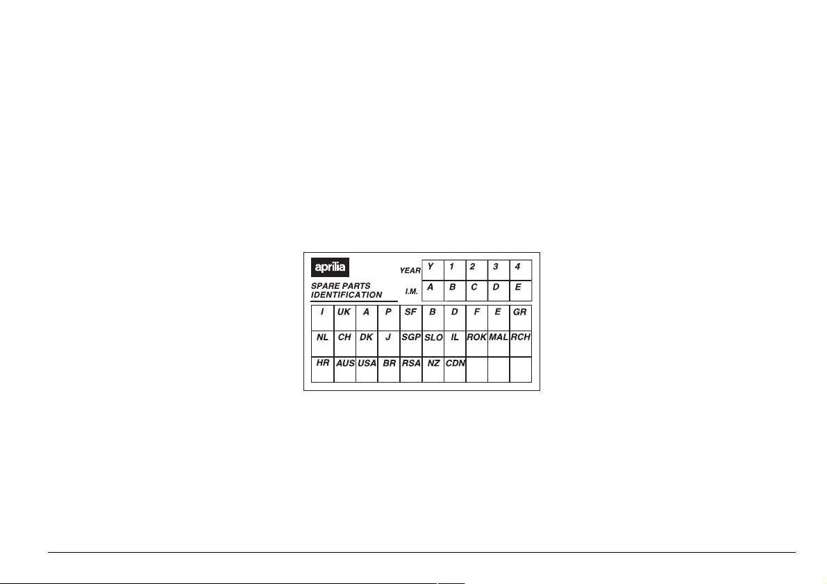
NOTE Soon after purchasing the vehi-
cle, write down the identification data indicated on the SPARE PARTS IDENTIFICATION LABEL in the table here below. The
label is positioned under the rider saddle,
see p. 66 (REMOVING THE RIDER SADDLE).
These data indicate:
– YEAR = year of manufacture (Y, 1, 2, ...);
– I.M. = modification code (A, B, C, ...);
– COUNTRY CODES = homologation
country (I, UK, A, ...).
and are to be supplied to the aprilia Official Dealer as reference data for the purchase of spare parts or specific accessories of the model you have acquired.
In this manual the various versions are indicated by the following symbols:
automatic light switching version
e
(Automatic Switch-on Device)
optional
m
VERSION:
Italy
I
United Kingdom
U
Austria
a
Portugal
p
Finland
F
Belgium
B
Germany
d
France
f
Spain
E
Greece
G
Holland
O
Switzerland
Y
Denmark
D
Japan
J
Singapore
S
Slovenia
s
Israel
i
South Korea
¬
Malaysia
M
Chile
c
Croatia
H
Australia
A
United States
u
of America
Brazil
Ä
South Africa
R
New Zealand
n
Canada
C
use and maintenance SL mille
3

4!",%/&#/.4%.43
SAFE DRIVE ......................................................... 5
BASIC SAFETY RULES ................................ 6
CLOTHING .................................................... 9
ACCESSORIES ........................................... 10
LOAD ........................................................... 10
ARRANGEMENT OF THE
MAIN ELEMENTS .............................................. 12
ARRANGEMENT OF THE
INSTRUMENTS/CONTROLS ............................14
INSTRUMENTS AND INDICATORS ................. 15
INSTRUMENTS AND INDICATORS TABLE 16
MULTIFUNCTION COMPUTER .................. 18
MAIN INDEPENDENT CONTROLS .................. 24
CONTROLS ON THE LEFT PART
OF THE HANDLEBAR ................................. 24
CONTROLS ON THE RIGHT PART
OF THE HANDLEBAR ................................. 25
IGNITION SWITCH ...................................... 26
STEERING LOCK ........................................ 26
AUXILIARY EQUIPMENT .................................. 27
UNLOCKING / LOCKING
THE PASSENGER SEAT ............................ 27
GLOVE/TOOL KIT COMPARTMENT .......... 28
LUGGAGE RACK FASTENINGS ................ 28
SPECIAL TOOLS
REAR MUDGUARD EXTENSION
MAIN COMPONENTS ........................................ 30
FUEL ............................................................ 30
BRAKE FLUID - recommendations ............. 31
DISC BRAKES ............................................. 31
FRONT BRAKE ........................................... 32
REAR BRAKE .............................................. 33
CLUTCH FLUID - recommendations ...........34
CLUTCH ...................................................... 35
COOLANT ................................................... 36
TYRES ......................................................... 38
ENGINE OIL ................................................ 39
ADJUSTING THE FRONT BRAKE
CONTROL LEVER AND THE CLUTCH
CONTROL LEVER ...................................... 40
& .................................. 29
& ......... 29
ADJUSTING THE REAR BRAKE
CONTROL LEVER CLEARANCE ................40
AUTOMATIC
LIGHT SWITCHING VERSION
EXHAUST SILENCERS / EXHAUST PIPES 41
INSTRUCTIONS FOR USE ................................42
PRELIMINARY
CHECKING OPERATIONS ..........................42
STARTING ...................................................43
DEPARTURE AND DRIVE ...........................46
RUNNING-IN ................................................49
STOPPING ...................................................49
PARKING .....................................................50
SUGGESTIONS TO PREVENT THEFT ......50
MAINTENANCE ..................................................51
REGULAR SERVICE INTERVALS CHART .52
IDENTIFICATION DATA ..............................54
JOINTS WITH CLICK CLAMPS
AND WITH SCREW CLAMPS .....................54
CHECKING THE ENGINE OIL LEVEL
AND TOPPING UP .......................................55
CHANGING THE ENGINE OIL
AND THE OIL FILTER .................................56
ASSEMBLING THE PINS FOR THE REAR
SUPPORT STAND
POSITIONING THE VEHICLE
ON THE REAR SUPPORT STAND
POSITIONING THE VEHICLE
ON THE FRONT SUPPORT STAND
AIR CLEANER .............................................59
FRONT WHEEL ...........................................60
REAR WHEEL ..............................................62
DRIVE CHAIN ..............................................64
REMOVING THE RIDER SADDLE ..............66
LIFTING THE FUEL TANK ...........................66
CHECKING THE BRAKE PAD WEAR .........67
INSPECTING THE FRONT
AND REAR SUSPENSIONS ........................68
FRONT SUSPENSION ................................68
REAR SUSPENSION ...................................70
IDLING ADJUSTMENT ................................72
& .................................58
_ ..............41
& .......58
& .....58
ADJUSTING
THE ACCELERATOR CONTROL ............... 72
ADJUSTING
THE COLD START CONTROL (
CHECKING THE SIDE STAND
AND THE SAFETY SWITCH ........................ 73
SPARK PLUGS ........................................... 74
BATTERY .................................................... 74
CHECKING AND CLEANING
THE TERMINALS ........................................ 75
REMOVING THE BATTERY ........................ 76
RECHARGING THE BATTERY ...................77
INSTALLING THE BATTERY ...................... 77
LONG INACTIVITY
OF THE BATTERY ...................................... 78
CHECKING THE SWITCHES ......................78
CHANGING THE FUSES ............................ 79
HORIZONTAL ADJUSTMENT OF THE
HEADLIGHT BEAM ...................................... 80
ADJUSTING THE VERTICAL
HEADLIGHT BEAM ..................................... 81
BULBS ......................................................... 81
CHANGING
THE HEADLIGHT BULBS ........................... 82
CHANGING THE FRONT AND REAR
DIRECTION INDICATOR BULBS ................ 83
CHANGING
THE REAR LIGHT BULB ............................. 84
CHANGING
THE NUMBER PLATE BULB ....................... 84
CLEANING ......................................................... 85
LONG PERIODS OF INACTIVITY ............... 86
TRANSPORT ..................................................... 86
TECHNICAL DATA ............................................ 87
LUBRICANT CHART ................................... 90
Importers .................................................92-93
WIRING DIAGRAM SL mille ........................ 94
WIRING DIAGRAM KEY SL mille ................95
e) ............ 72
use and maintenance SL mille
4
safe drive
"!3)#3!&%4925,%3
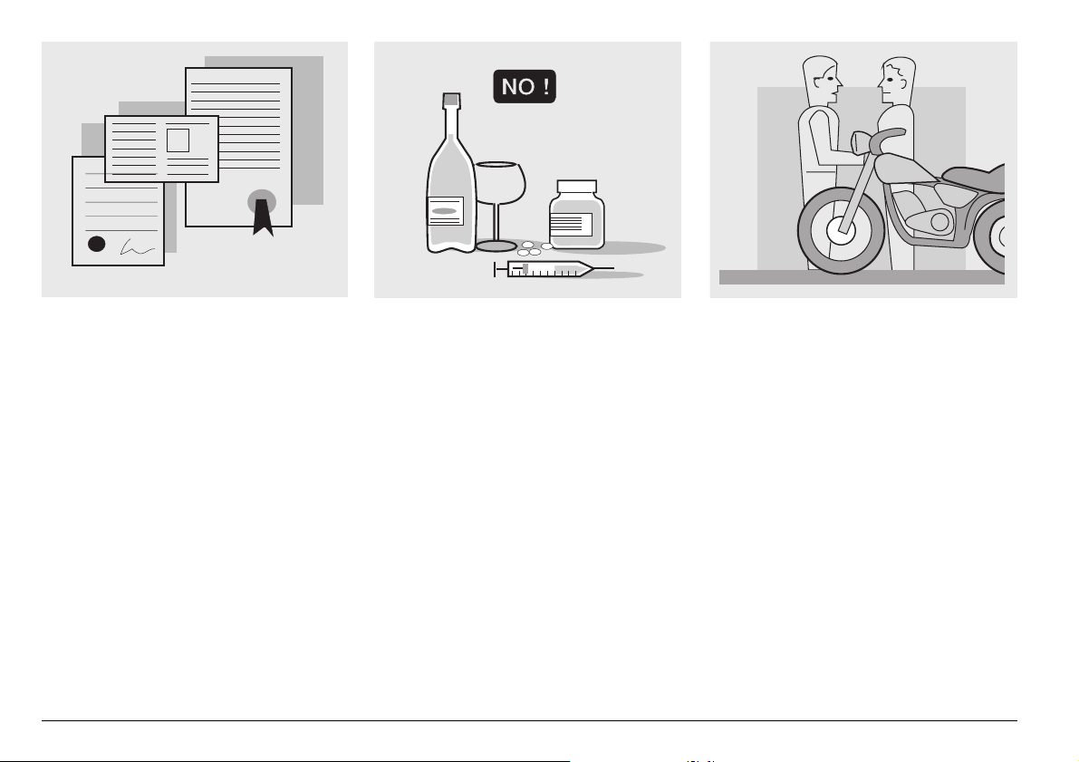
To drive the vehicle it is necessary to be in
possession of all the requirements prescribed by law (driving licence, minimum
age, psychophysical ability, insurance,
state taxes, vehicle registration, number
plate, etc.).
Gradually get to know the vehicle by driving it first in areas with low traffic and/or private areas.
use and maintenance SL mille
6
The use of medicins, alcohol and drugs or
psychotropic substances notably increases
the risk of accidents.
Be sure that you are in good psychophysical conditions and fit for driving and pay
particular attention to physical weariness
and drowsiness.
Most road accidents are caused by the
driver’s lack of experience.
NEVER lend the vehicle to beginners and,
in any case, make sure that the driver has
all the requirements for driving.
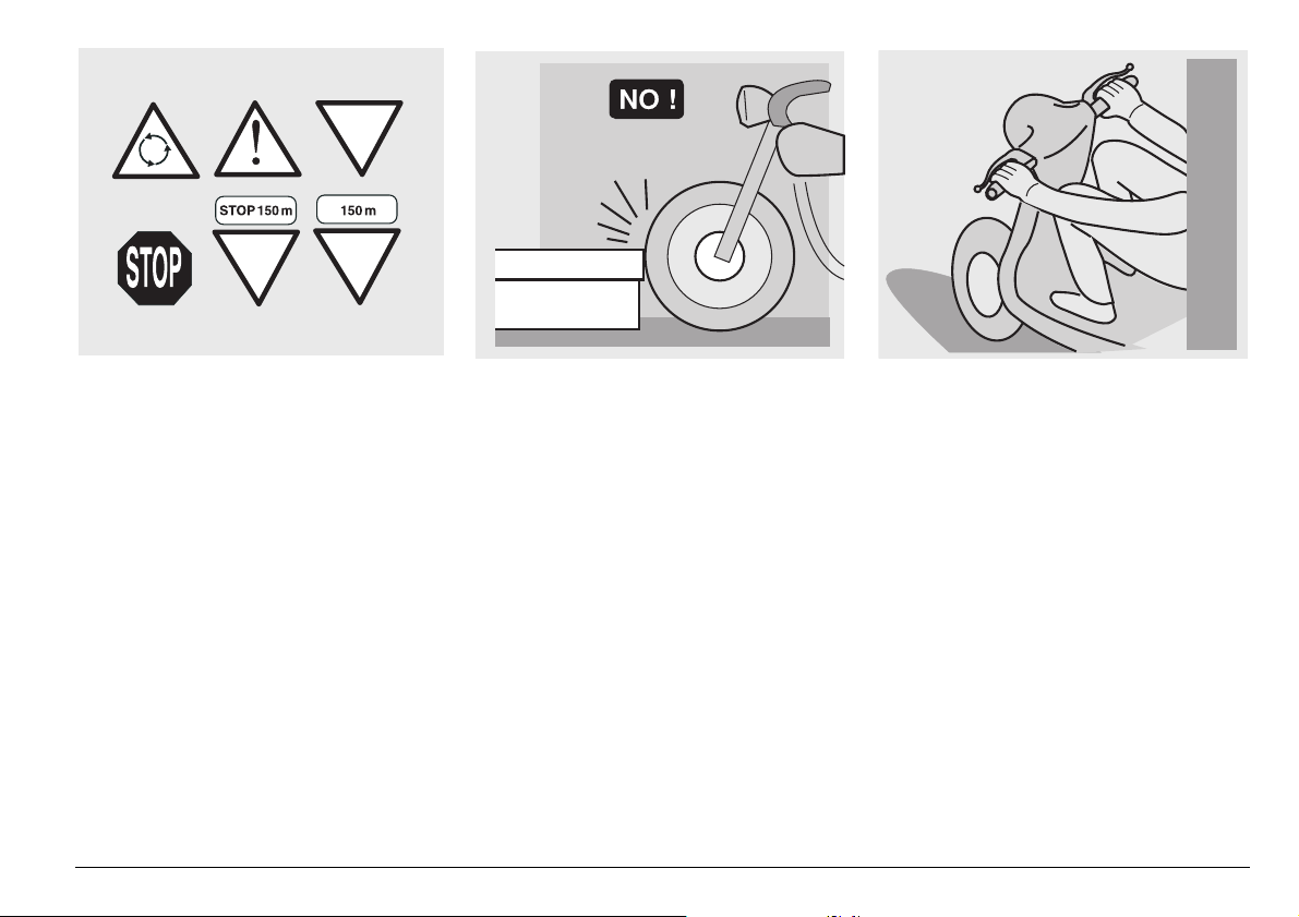
Rigorously observe all road signs and national and local road regulations.
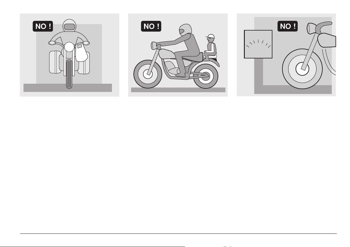
Avoid abrupt movements that can be dangerous for yourself and other people (for
example: rearing up on the back wheel,
speeding, etc.), and give due consideration
to the road surface, visibility and other driving conditions.
Avoid obstacles that could damage the vehicle or make you lose control.
Avoid riding in the slipstream created by
preceding vehicles in order to increase
your speed.
Always drive with both hands on the handlebars and both feet on the footrests (or
on the rider’s footboards), in the correct
driving posture.
Avoid standing up or stretching your limbs
while driving.
use and maintenance SL mille
7
OIL
COOLER
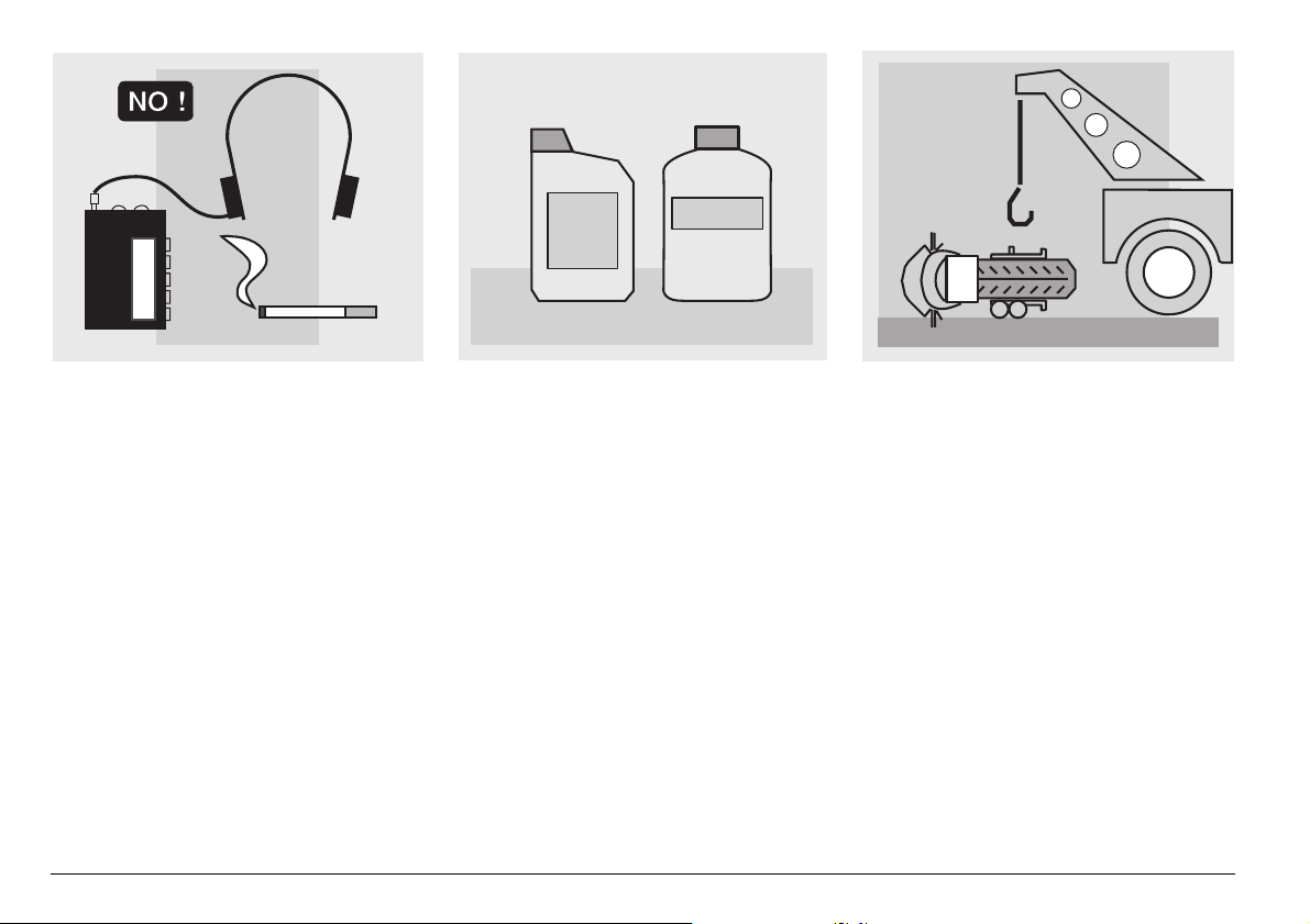
The driver should pay attention and avoid
distractions caused by people, things and
movements (never smoke, eat, drink, read,
etc.) while driving.
use and maintenance SL mille
8
Use only the vehicle’s specific fuels and lubricants indicated in the “LUBRICANT
CHART”; check the oil, fuel and coolant
levels regularly.
If the vehicle has been involved in an accident, make sure that no damage has occurred to the control levers, pipes, wires,
braking system and vital parts.
If necessary, have the vehicle inspected by
an aprilia Official Dealer, who should carefully check the frame, handlebars, suspensions, safety parts and all the devices that
you cannot check by yourself.
Always remember to report any malfunction to the technicians to help them in their
work.
Never use the vehicle when the amount of
damage it has suffered endangers your
safety.
ONLY ORIGINALS
A12
345
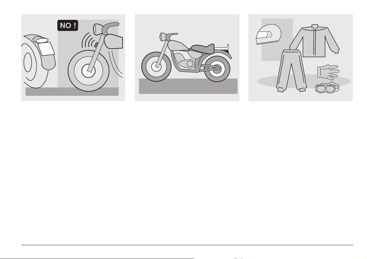
Never change the position, inclination or
colour of: number plate, direction indicators, lights and horns.
Any modification of the vehicle will result in
the invalidity of the guarantee.
Any modification of the vehicle and/or the
removal of original components can compromise vehicle performance levels and
safety or even make it illegal.
We recommend respecting all regulations
and national and local provisions regarding
the equipment of the vehicle.
In particular, avoid all modifications that increase the vehicle’s performance levels or
alter its original characteristics.
Never race with other vehicles.
Avoid off-road driving.
#,/4().'
Before starting, always wear a correctly
fastened crash helmet. Make sure that it is
homologated, in good shape, of the right
size and that the visor is clean.
Wear protective clothing, preferably in light
and/or reflecting colours. In this way you
will make yourself more visible to the other
drivers, thus notably reducing the risk of
being knocked down, and you will be more
protected in case of fall.
This clothing should be very tight-fitting
and fastened at the wrists and ankles.
Strings, belts and ties should not be hanging loose; prevent these and other objects
from interfering with driving by getting entangled with moving parts or driving mechanisms.
use and maintenance SL mille
9
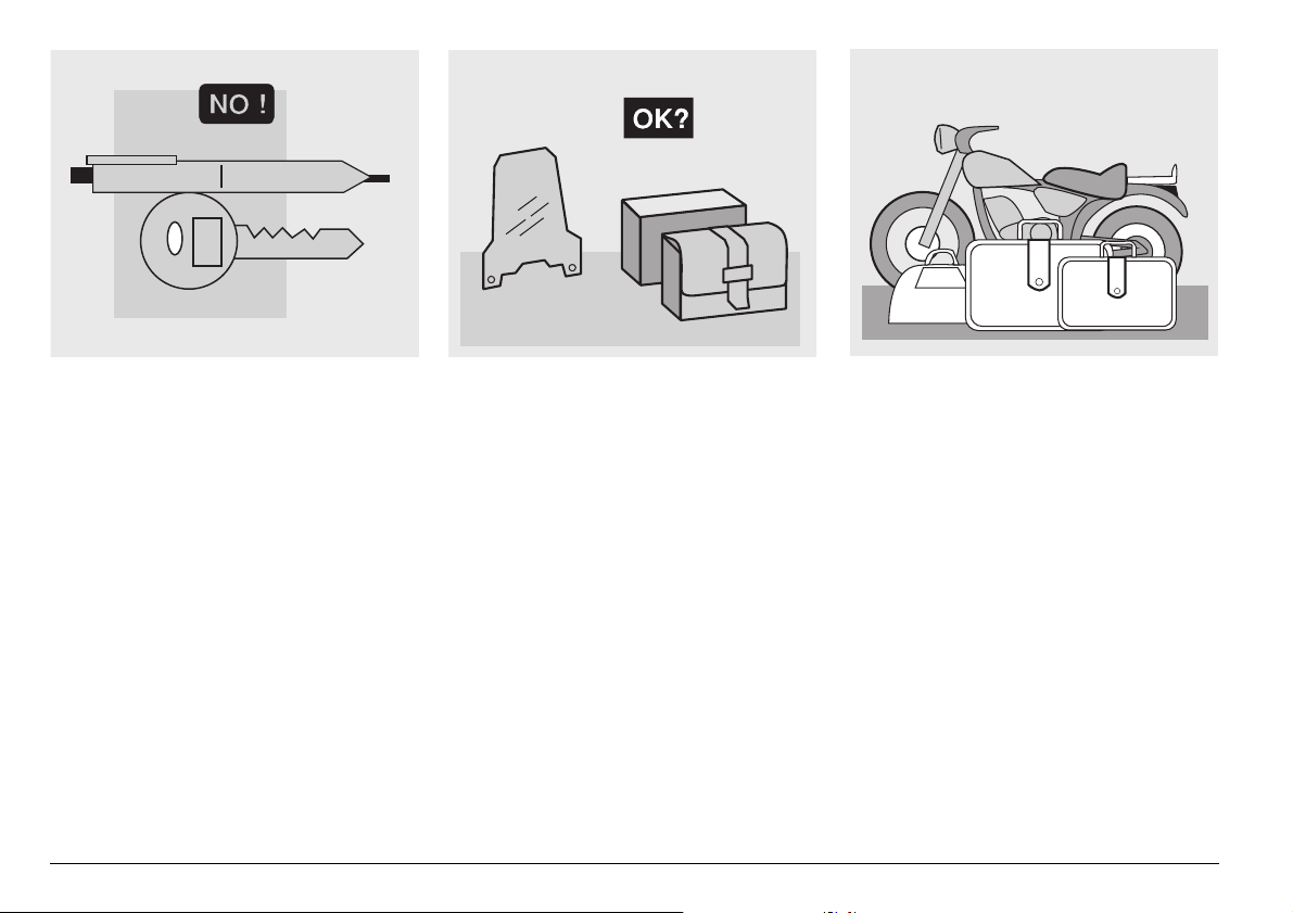
Do not keep objects that can be dangerous
in case of fall, for example pointed objects
like keys, pens, glass vials etc. in your
pockets (the same recommendations also
apply to passengers).
use and maintenance SL mille
10
!##%33/2)%3
The owner of the vehicle is responsible for
the choice, installation and use of any accessory.
Avoid installing accessories that cover
horns or lights or that could impair their
functions, limit the suspension stroke and
the steering angle, hamper the operation of
the controls and reduce the distance from
the ground and the angle of inclination in
turns.
Avoid using accessories that hamper access to the controls, since this can prolong
reaction times during an emergency.
Large fairings and windscreens assembled
on the vehicle can produce aerodynamic
forces capable of compromising the stability of the vehicle while driving.
Make sure that the equipment is well fastened to the vehicle and not dangerous
during driving. Do not install electrical devices and do not modify those already existing to avoid electrical overloads, because the vehicle could suddenly stop or
there could be a dangerous current shortage in the horn and in the lights. aprilia
recommends the use of genuine accessories (aprilia genuine accessories).
,/!$
Be careful and moderate when loading
your luggage. Keep any luggage loaded as
close as possible to the centre of the vehicle and distribute the load uniformly on
both sides, in order to reduce imbalance to
the minimum. Furthermore, make sure that
the load is firmly secured to the vehicle, especially during long trips.
KG!
Avoid hanging bulky, heavy and/or dangerous objects on the handlebars, mudguards
and forks, because the vehicle might respond more slowly in turns and its manoeuvrability could be unavoidably impaired.
Do not place bags that are too bulky on the
vehicle sides and do not ride with the crash
helmet hanging from its string, because it
could hit people or obstacles making you
lose control of the vehicle.
Do not carry any bag if it is not tightly secured to the vehicle.
Do not carry bags which protrude too much
from the luggage rack or which cover the
lights, horn or indicators.
Do not carry animals or children on the
glove compartment or on the luggage rack.
Do not exceed the maximum load allowed
for each side-bag.
When the vehicle is overloaded, its stability
and its manoeuvrability can be compromised.
use and maintenance SL mille
11
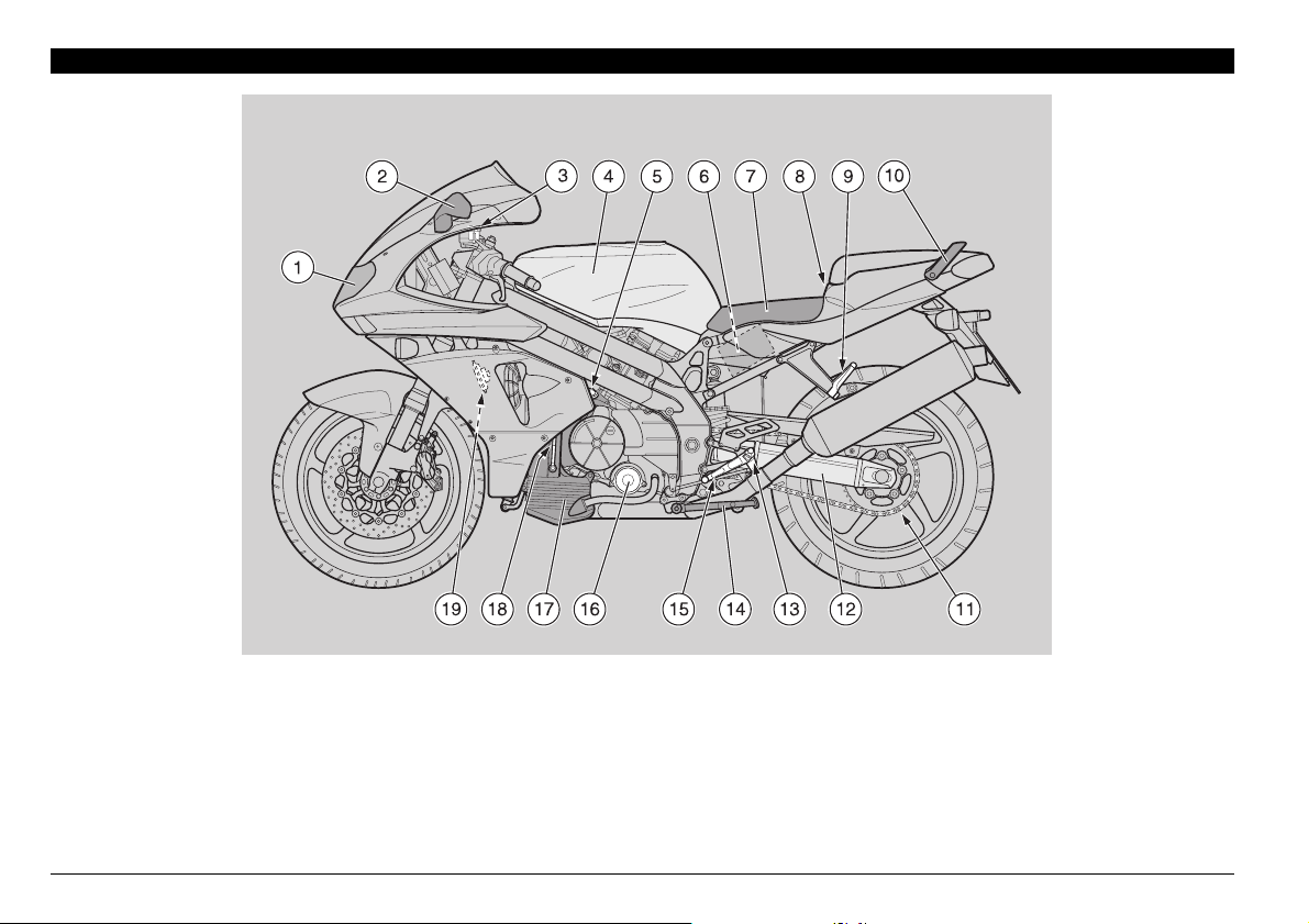
!22!.'%-%.4/& 4(%-!).%,%-%.43
+%9
1) Headlight
2) Left rear-view mirror
3) Clutch fluid reservoir
4) Fuel tank
5) Engine oil tank cap
6) Battery
7) Rider saddle
8) Glove/tool kit compartment lock
use and maintenance SL mille
12
9) Passenger left footrest
(snapping, closed/open)
10) Passenger grab rail
11) Drive chain
12) Rear fork
13) Rider left footrest
(with spring, always open)
14) Side stand
15) Shifting lever
16) Engine oil filter
17) Engine oil tank
18) Engine oil level
19) Horn
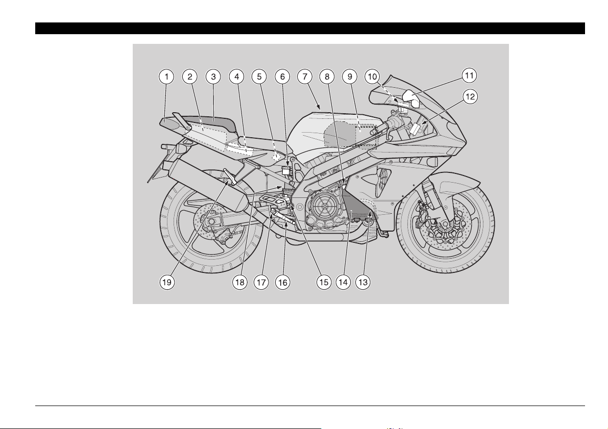
+%9
1) Rear light
2) Glove/tool kit compartment
3) Passenger seat
(alternatively: glove/tool kit compartment cover)
4) Electronic unit
5) Main fuse carrier (30 A)
6) Rear brake fluid tank
7) Fuel tank plug
8) Coolant expansion tank cap
9) Air cleaner
10) Front brake fluid tank
11) Right rear-view mirror
12) Secondary fuse carrier (15 A)
13) Coolant level
14) Expansion tank
15) Rear brake pump
16) Rear brake control lever
17) Rider right footrest
(with spring, always open)
18) Rear shock absorber
19) Passenger right footrest
(snapping, closed/open)
use and maintenance SL mille
13
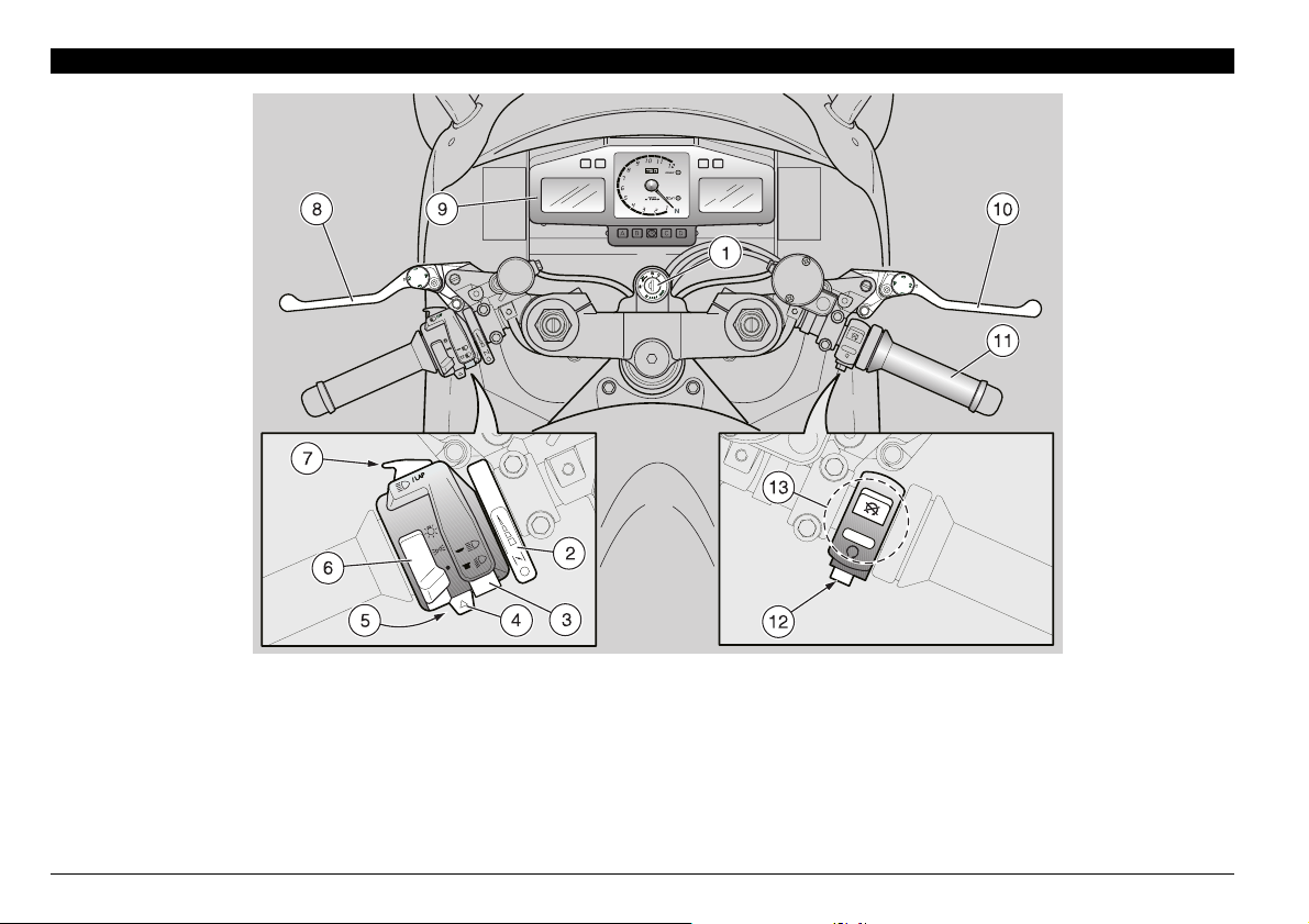
!22!.'%-%.4/& 4(%).3425-%.43#/.42/,3
+%9
1) Ignition switch/steering lock (
2) Cold start lever (
3) Dimmer switch (
4) Direction indicator switch ( c )
5) Horn push button (
6) Light switch (
7) High beam signaller push button (a) LAP push button (multifunction)
e)
b - a )
f )
o - p - • ) (not provided for
n - m - s)
_
)
8) Clutch lever
9) Instruments and indicators
10) Front brake lever
11) Throttle grip
12) Start push button (
13) Engine stop switch (
r)
n - m)
use and maintenance SL mille
14
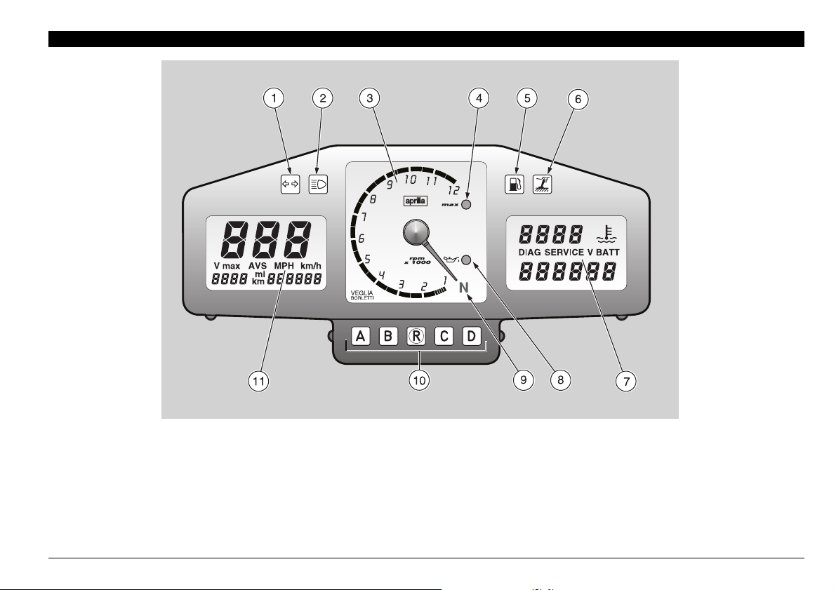
).3425-%.43!.$ ).$)#!4/23
+%9
1) Green direction indicator warning light (
2) Blue high beam warning light (
3) Revolution counter
4) Programmable red line warning light LED ( max )
5) Amber low fuel warning light (
6) Amber “side stand down” warning light ( \ )
a )
g)
c )
7) Right multifunction digital display (coolant temperature - clock
- battery voltage - chronometer - diagnostic)
8) Red engine oil pressure warning light LED (
9) Green neutral indicator warning light (q )
10) Multifunction computer programming push buttons
11) Left multifunction digital display (speedometer - odometer)
j )
use and maintenance SL mille
15
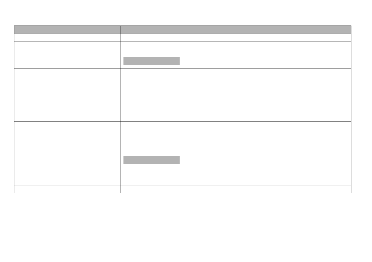
).3425-%.43!.$).$)#!4/234!",%
Description Function
Direction indicator warning light
High beam warning light
Revolution counter rpm
Programmable red line
warning light LED max
Low fuel warning light
Side stand down warning light
Engine oil pressure
warning light LED
c Blinks when the direction indicators are on.
a Comes on when the high beam bulbs are on or when the headlight signaller is operated.
Indicates the number of revolutions of the engine per minute.
a
Blinks when the max. rpm set by the user is reached, see p. 20 (SETTING THE RED LINE
THRESHOLD (WITH ENGINE OFF ONLY)).
It comes on when the engine max. rpm threshold setting is confirmed, see p. 20 (SETTING THE
RED LINE THRESHOLD (WITH ENGINE OFF ONLY)) and whenever the ignition key is rotated
to position “
Comes on when the quantity of fuel left in the tank is about 4.5 ± 1 L.
g
In this case, top up as soon as possible, see p. 30 (FUEL).
Comes on when the side stand is down.
\
Comes on, whenever the ignition switch is brought to position “n”, thus testing the correct operation of the LED.
If the light LED does not come on in this phase, contact an aprilia Official Dealer.
j
a
gine oil pressure in the circuit is insufficient.
CAUTION
Never exceed the engine max. speed rate, see p. 49 (RUNNINGIN).
n”, for about three seconds, see p. 18 (MULTIFUNCTION COMPUTER).
CAUTION
If the engine oil pressure warning light LED “
ring the normal operation of the engine, this means that the en-
” comes on du-
j
Neutral indicator warning light
use and maintenance SL mille
16
In this case, stop the engine immediately and contact an
q Comes on when the gear is in neutral.
APRILIA Official Dealer.
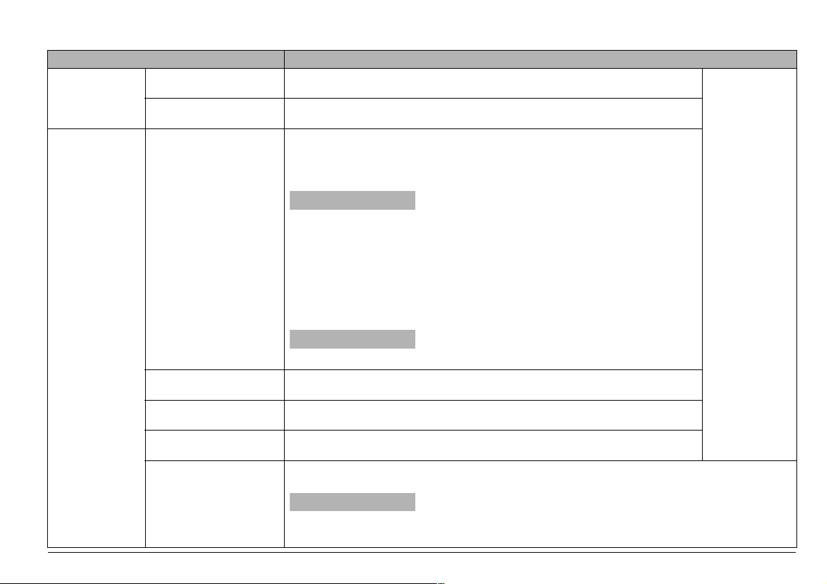
Description Function
Multifunction
digital display
(left side)
Speedometer
(km/h - MPH)
Odometer (km - mi) Indicates the partial or total number of kilometres or miles covered.
Indicates the instantaneous, average or maximum driving speed (in kilometres or
miles) according to the presetting, see p. 18 (MULTIFUNCTION COMPUTER).
Indicates the temperature of the coolant in the engine, see p. 18 (MULTIFUNCTION COMPUTER).
If a temperature of 115 ÷ 120 °C (239 ÷ 248 °F) is indicated, stop the engine
and check the coolant level, see p. 36 (COOLANT).
a
pendently of the coolant temperature and in this case the tempera-
Coolant
temperature
(°C / °F)
Multifunction
digital display
(right side)
Clock
Battery voltage
V BATT
Chronometer
Diagnostics
ture would increase further.
If the writing “
h
3000 rpm for approximately two minutes, thus allowing the coolant to circulate regularly in the system; then press the engine stop switch to position “
m “ and check the coolant level, see p. 36 (COOLANT).
If the writing “
cked, contact an aprilia Official Dealer.
a
riously damaged.
Indicates the hour and minutes according to the presetting, see p. 18 (MULTIFUNCTION COMPUTER).
Indicates the battery voltage, see p. 18 (MULTIFUNCTION COMPUTER).
Indicates the various timings according to the presetting, see p. 18 (MULTIFUNCTION COMPUTER).
Whenever the ignition switch is turned to position “n”, the writing “HIL” ” is displayed for
about three seconds.
a
ed an anomaly. In many cases, the engine keeps running with reduced performance
levels; immediately contact an APRILIA Official Dealer.
CAUTION
Do not turn the ignition switch to position
“m”, since the cooling fans would stop inde-
///” is displayed, stop the vehicle and let the engine run at
///” is still displayed after the coolant level has been che-
CAUTION
CAUTION
If the maximum allowed temperature (120°C 248 °F) is exceeded, the engine may be se-
If the writing “HIL” is displayed during the normal operation
of the engine, this means that the electronic unit has detect-
To a lter na te th e
data displayed,
see p. 18
(MULTIFUNCTION COMPUTER).
use and maintenance SL mille
17
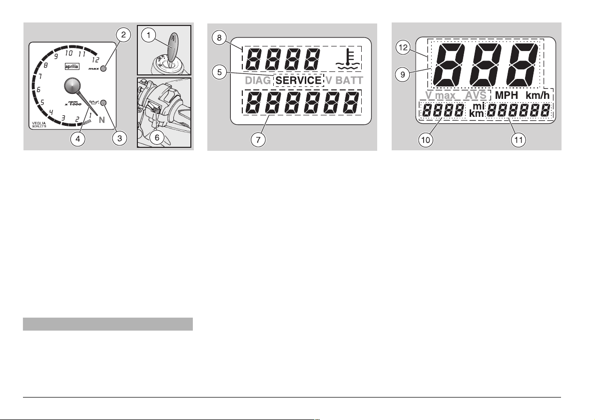
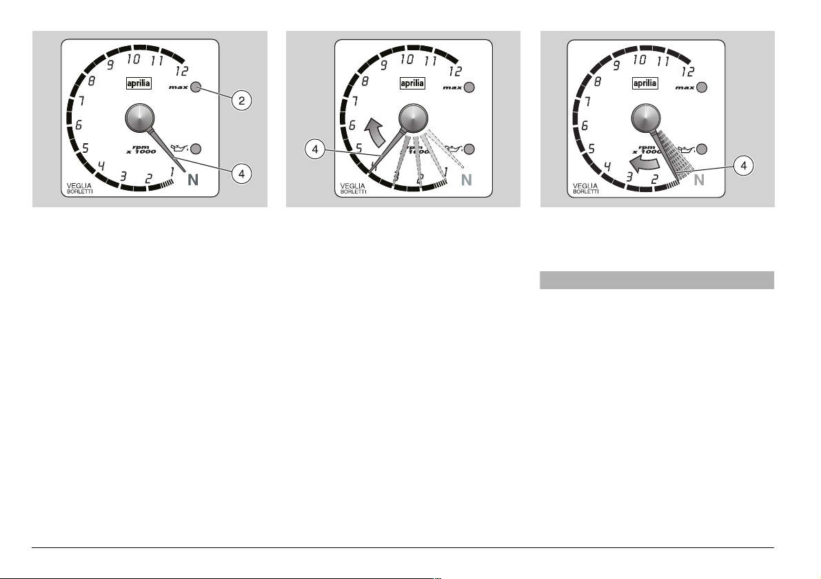
-5,4)&5.#4)/.#/-054%2
When the ignition key (1) is rotated to position “n”, the following warning lights come
on on the dashboard:
– red line warning light LED “max” (2).
– red engine oil pressure warning light
LED (
j) (3), which remains on until the
engine starts.
The pointer (4) of the revolution counter
shifts to the maximum value (rpm) set by
the user. After about three seconds the red
line warning light LED “max” (2) goes off;
the pointer (4) of the revolution counter returns to its initial position. In this way the
component operation is tested.
aCAUTION
After the first 1000 km (625 mi) and successively every 7500 km (4687 mi), the
writing “SERVICE” (5) appears on the
right display. In this case contact an
APRILIA Official Dealer, who will carry
out the operations indicated in the regu-
use and maintenance SL mille
18
lar service intervals chart, see p. 52-53
(REGULAR SERVICE INTERVALS
CHART). To make the writing “SERVICE” disappear, press the “LAP” push
button (6) and then the push button
and keep them pressed for about 5 seconds.
With the ignition key (1) in position
standard settings on the dashboard are the
following:
Right display: Clock (7), coolant temperature in °C (8).
Left display: Instantaneous speed in km/h
(9), trip 1 (trip odometer) (10), total kilometres/miles odometer (11).
Upon installation of the battery or of the
30A main fuses:
– The revolution counter pointer (4) makes
12 clockwise clicks, thus checking the
operation of the revolution counter itself.
– The instantaneous, maximum and aver-
age speed function is set in “km/h”.
R
“n” the
– The coolant temperature is set in °C.
– The digital clock is set to zero.
– The red line is set at 6000 rpm, indicated
by the coming on of the red line warning
light LED “max ” (red) (2).
NOTE If necessary, carry out the appro-
priate adjustments.
SEGMENT OPERATION CHECK
◆
Press the push buttons A and B at the
same time.
◆
Rotate the ignition key (1) from position
“
m” to position “n”.
All the segments will remain on until the
push buttons
SWITCHING FROM km TO mi (from
km/h to MPH) AND VICEVERSA (LEFT
DISPLAY)
◆
Press the push button A until, after
about 5 seconds, all the writings (12) on
the left display start blinking.
◆
Release the push button A.
A and B are released.
◆
Press the push button B to change the
unit of measurement from “km” to “mi”
(from “km / h” to “MPH”) and viceversa.
◆
To confirm the setting, press the push
A for about 5 seconds.
button
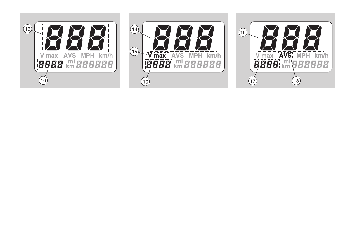
SETTING THE INSTANTANEOUS, MAXIMUM AND AVERAGE SPEED (LEFT DISPLAY)
NOTE Two seconds after the vehicle has
started moving, the instantaneous speed is
automatically shown on the display, even if
a different function is set.
When the ignition key is rotated to position
n”, the instantaneous speed (13) and the
“
partial number of kilometres/miles covered
(trip 1) (10) appear on the left display.
Resetting “trip 1” (10): with the odometer
set on the instantaneous speed function,
press the push button
onds.
R for about 2 sec-
◆
To display the maximum speed (14) and
the distance “trip 1” (10), press the push
B for about 1 second.
button
The writing “V max” (15), the maximum
speed (14) and the distance “trip 1” (10)
are displayed.
Resetting the maximum speed (14): with
the odometer set on the “V max” function,
press the push button
onds.
R for about 2 sec-
NOTE The measurement of the maxi-
mum speed is relevant to the distance covered from the last setting to zero of the maximum speed itself. The distance “trip 1” (10)
shown on the display indicates the number
of kilometres/miles covered from the last setting to zero, to the distance “trip 1”.
◆
To display the average speed (16) and
the distance “trip 2” (17), press the push
B again for about 1 second.
button
The writing “AVS” (18), the average speed
(16) and the distance “trip 2” (17) are displayed.
Resetting the average speed (16) and the
distance “trip 2” (17): with the odometer set
on the “AVS” function, press the push but-
R for about 1 second.
ton
NOTE The measurement of the average
speed is relevant to the distance “trip 2”
(odometer).
The distance “trip 2” (17) shown on the display indicates the number of kilometres/miles covered from the last setting to
zero.
If more than 1000 km (625 mi) are covered
without setting “trip 2” to zero, the value of
the average speed will be wrong.
◆
To display the instantaneous speed (13)
and the distance “trip 1” (10), press the
push button
B again.
use and maintenance SL mille
19
SETTING THE RED LINE THRESHOLD
(WITH ENGINE OFF ONLY)
When the maximum rpm set is exceeded, the red line warning light LED “
(2) positioned on the dashboard starts
blinking.
If the push button
than one second, the pointer of the revolution counter (4) shifts to the red line value
set for 3 seconds, after which it returns to
its initial position.
use and maintenance SL mille
20
C is pressed for less
max”
For the setting:
◆
Press the push button C, release it and
press it again within 3 seconds.
The pointer (4) moves increasing the value by 1000 rpm at each click, as long as
C is kept pressed; when it has reached
the maximum value, it starts again from
the beginning.
◆
Press the push button C until the desired rpm value has been set.
◆
If the push button C is released and then
pressed again within 3 seconds, intermittently, the pointer (4) moves increasing
the value by 100 rpm at each click; when
it has reached the maximum value, it
starts again from the beginning.
NOTE It is not possible to set the red line
at values lower than 2000 rpm or higher
than 12000 rpm.
aCAUTION
Never exceed the recommended rpm,
see p. 49 (RUNNING-IN).
◆
To confirm, release the push button C.
After 3 seconds, the red line threshold
setting is stored.
NOTE The setting is confirmed by the
coming on of the red line warning light LED
max” (2).
“
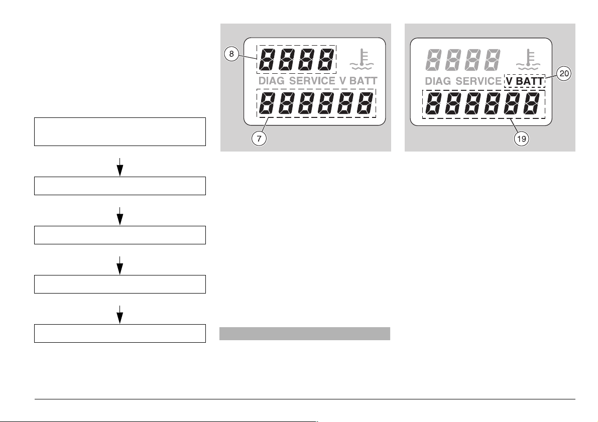
MULTIFUNCTION (RIGHT DISPLAY)
The right display (multifunction) includes
the coolant temperature in °C (°F) (8) and
the digital clock (7) as standard settings.
NOTE When the engine is cold, the writ-
×” blinks.
ing “
By pressing the push button
ing functions can be obtained in sequence:
D, the follow-
temperature in °C and digital clock
Standard setting:
D
Battery voltage (V BATT)
D
Hour setting
D
Minute setting
D
°C or °F setting
STANDARD SETTING:
COOLANT TEMPERATURE
AND DIGITAL CLOCK
The coolant temperature value (8) is
shown in the upper part of the right display.
It is possible to switch from °C to °F and
viceversa, see p. 22 (SETTING °C OR °F).
– When the temperature is below 35°C
(95°F), the writing “
the right display.
– When the temperature is over 115°C
(239°F), the value (8) blinks on the right
display, even if a function different from
the standard setting has been set.
– When the temperature is over 130°C
(266°F), the writing “///” (8) appears
on the right display.
×” (8) blinks on
aCAUTION
If the writing “///” is displayed with a
temperature below 130°C (266°F), there
may be a failure of the electric circuit. In
this case, contact an APRILIA Official
Dealer.
Thermometer range on the display:
35 – 130°C (95 – 266 °F).
The digital clock (7) appears in the lower
part of the right display.
To set or modify hour and minutes, see p.
22 (SETTING THE HOUR) and p. 22
(SETTING THE MINUTES).
BATTERY VOLTAGE - VBATT
◆
If the push button D is pressed once, the
battery voltage expressed in volt (19) appears in the lower part of the right display, while the coolant temperature (8)
is displayed in the upper part.
The writing “V BATT” (20) is displayed.
The recharge circuit functions correctly
if at 4000 rpm the battery voltage with
low beam on is included between 13
and 15 V.
use and maintenance SL mille
21
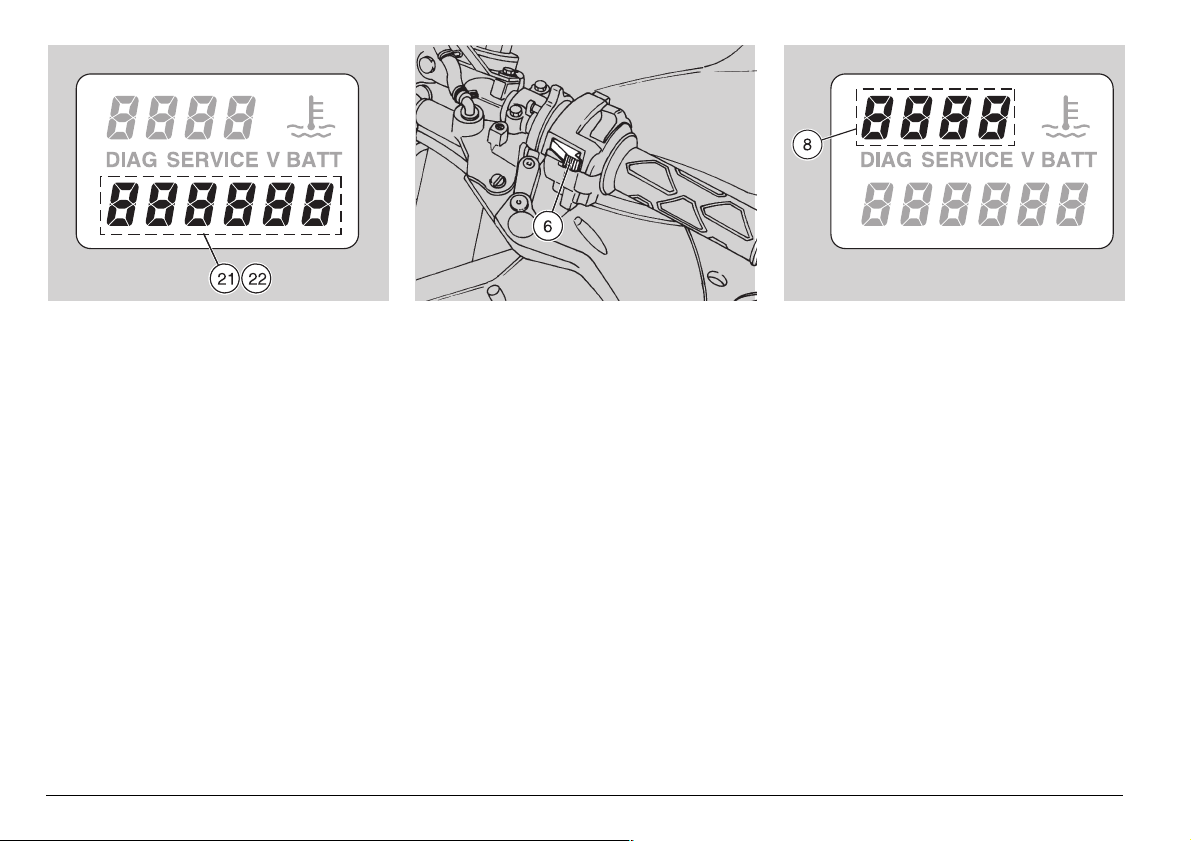
SETTING THE HOUR
◆
When the push button D is pressed for
the second time, the hour segments (21)
start blinking in the lower part of the right
display (digital clock).
◆
To modify the hour setting, press the
“LAP” push button (6) on the left part of
the handlebar.
◆
To confirm the hour setting, press the
push button D.
use and maintenance SL mille
22
SETTING THE MINUTES
◆
When the push button D is pressed for
the third time, the minute segments (22)
start blinking in the lower part of the right
display (digital clock).
◆
To modify the minute setting, press the
“LAP” push button (6) on the left part of
the handlebar.
◆
To confirm the minute setting, press the
push button D.
SETTING °C OR °F
◆
When the push button D is pressed for
the fourth time, the segments of the coolant temperature in °C or °F (8) start
blinking in the upper part of the display.
◆
To modify from °C to °F setting, or vice
versa, press the “LAP” push button (6)
on the left part of the handlebar.
◆
To confirm the setting, press the push
button D.
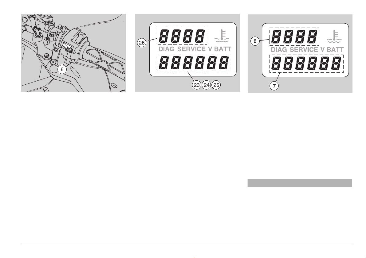
CHRONOMETER (RIGHT DISPLAY)
The chronometer makes it possible to
measure the time per lap with the vehicle
on a racetrack and to store the data, in
such a way as to be able to consult them
successively.
When the “CHRONOMETER” function has
been selected, it is not possible to recall
the following functions:
– Maximum speed “V max”
– Average speed “AVS”
– Distance “trip 2”.
◆
To operate the chronometer, press the
“LAP” push button (6) and, within 0.7
seconds, the push button
◆
To start timing, press the “LAP” push
button (6) and release it immediately.
◆
To store the time acquired, press the
“LAP” push button (6).
D.
The “LAP” push button (6) is not enabled
for 10 seconds and the last time stored
(23) is shown on the display.
After which, the chronometer with the current timing (24) is displayed, starting from
10 seconds.
◆
To display the first time stored (25),
press the push button
◆
To be able to see the stored times in sequence, press the “LAP” push button (6).
The writings
(26) are displayed.
◆
To start timing again, press the push but-
B.
ton
/, / , /, /, etc.
B.
NOTE It is possible to store max. 40
times, after which the “LAP” push button
(6) is not effective any longer.
◆
To set the memory to zero, press the
push button
ton (6) at the same time for 2 seconds.
◆
To leave the chronometer function, press
A and the “LAP” push but-
the “LAP” push button (6) and the push
button D.
The coolant temperature (8) and the digital
clock (7) appear on the right display (multifunction).
NOTE When the engine is cold, the writ-
×” is displayed.
ing “
DIAGNOSTICS
Whenever the ignition switch is turned to
position “
played for about three seconds.
n”, the writing “(),” is dis-
aCAUTION
If the writing “(),” is displayed during
the normal operation of the engine, this
means that the electronic unit has detected an anomaly. In many cases, the
engine keeps running with reduced performance levels; immediately contact an
APRILIA Official Dealer.
use and maintenance SL mille
23
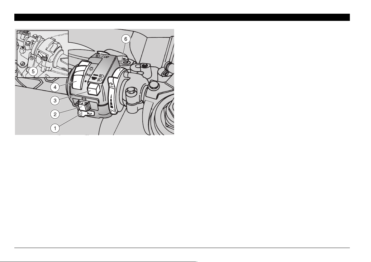
-!).).$%0%.$%.4 #/.42/,3
#/.42/,3/.4(%,%&40!24
/&4(%(!.$,%"!2
NOTE The electrical parts work only when the ignition switch is
in position “
1) HORN PUSH BUTTON (
The horn is activated when the push button is pressed.
2) DIRECTION INDICATOR SWITCH (
To indicate the turn to the left, move the switch to the left; to
indicate the turn to the right, move the switch to the right.
To turn off the direction indicator, press the switch.
n”.
f )
c )
3) DIMMER SWITCH (
When the light switch is in position “o”: if the dimmer switch
is in position “
b”, the low beam comes on.
sition “
3) DIMMER SWITCH (
When it is in position “
light and the low beam are always on.
When it is in position “
4) HEADLIGHT SWITCH (
(not provided in the
When the light switch is in position “
the switch is in position “p”, the parking lights and the dashboard light are on; when the switch is in position “
parking lights, the dashboard light and the low beam are on.
The high beam can be operated by means of the dimmer
switch.
5) HIGH BEAM SIGNALLER PUSH BUTTON (
LAP (multifunction)
b - a)
a”, the high beam comes on, while if it is in po-
b - a)
_
b” the parking lights, the dashboard
a”, the high beam comes on.
o - p -
version)
_
)
•
”, the lights are off; when
•
o”, the
a) /
NOTE For the setting of the functions, see p. 18 (MULTI-
FUNCTION COMPUTER).
This push button makes it possible to use the high beam signaller in case of danger or emergency, or displays the various
preset functions on the right multifunction display:
– hour and minutes;
– coolant temperature (°C or °F);
– chronometer.
use and maintenance SL mille
24
The high beam blinking is operated by pressing the push
button, independently of the position of the light switch (
o -
p - •).
NOTE To disconnect the high beam blinking, release the
push button.
6) COLD START LEVER (
The starter for the cold start of the engine is operated by rotating the lever “
To disconnect the starter, move the lever “
sition.
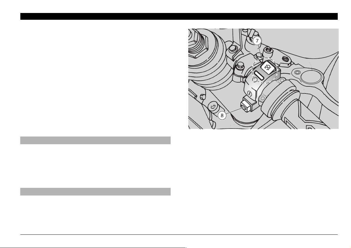
#/.42/,3/.4(%2)'(40!24
/&4(%(!.$,%"!2
e” downwards.
e)
e” to its initial po-
NOTE The electrical parts work only when the ignition switch is
in position “n”.
7) ENGINE STOP SWITCH (
n - m)
aWARNING
Do not operate the engine stop switch “n - m” in running
conditions.
This is a safety or emergency switch.
With the switch in position “
gine; the engine can be stopped by moving the switch to posi-
m”.
tion “
n”, it is possible to start the en-
aCAUTION
With stopped engine and ignition switch in position “n”,
the battery may discharge.
When the vehicle has come to rest, after stopping the engine, move the ignition switch to position “
m”.
8) START PUSH BUTTON (
When the start push button “r” is pressed, the starter makes
the engine run. For the starting, see p. 43 (STARTING).
r)
use and maintenance SL mille
25
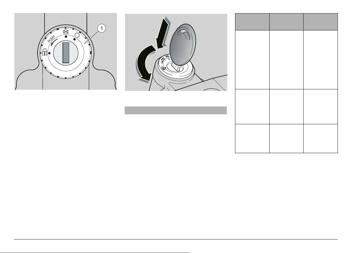
Position Function
Key
removal
)'.)4)/.37)4#(
The ignition switch (1) is positioned on the
upper plate of the steering column.
NOTE The key operates the ignition
switch/steering lock, the fuel tank lock and
the glove/tool kit compartment lock.
Two keys are supplied together with the
vehicle (one spare key).
NOTE Do not keep the spare key on the
vehicle.
34%%2).',/#+
aWARNING
Never turn the key to position “s” in
running conditions, in order to avoid
losing control of the vehicle.
OPERATION
To lock the steering:
◆
Turn the handlebar completely leftwards.
◆
Turn the key to position “m”.
◆
Press the key and rotate it to position “s”.
◆
Extract the key.
s
Steering
lock
m
n
The steering is
locked.
It is neither
possible to
start the
engine, nor
to switch on
the lights.
Neither the
engine, nor
the lights
can be
switched on.
The engine
and the
lights can be
switched on.
It is possible to
remove the
key.
It is possible to
remove the
key.
It is not possible to
remove the
key.
use and maintenance SL mille
26
!58),)!29%15)0-%.4
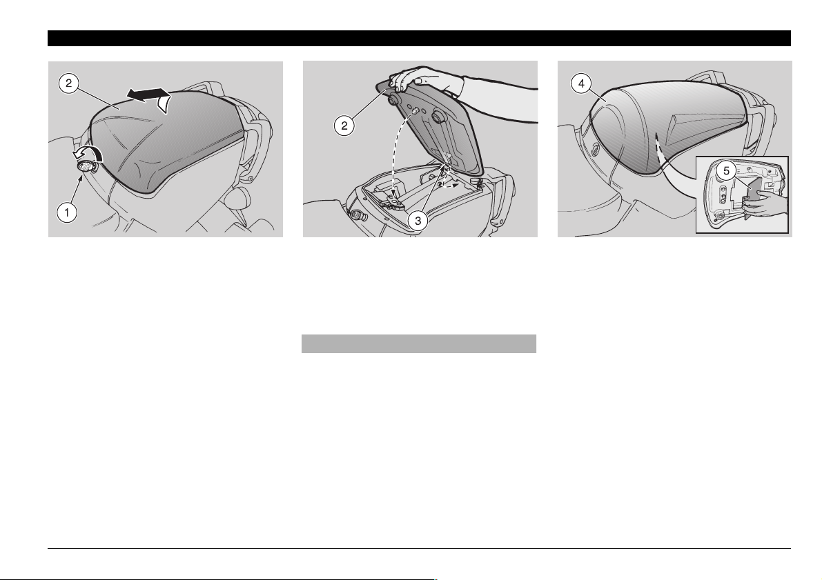
5.,/#+).',/#+).'
4(%0!33%.'%23%!4
◆
Position the vehicle on the side stand on
firm and level ground.
◆
Introduce the key (1) in the seat lock.
◆
Turn the key (1) anticlockwise, raise and
withdraw the seat (2) from the front.
NOTE Before lowering and locking the
seat (2), make sure that you have not left
the key in the glove / tool kit compartment.
To lock the seat (2), proceed as follows:
◆
Introduce the lower point (3) under the
rear saddle support plate.
◆
Position the seat and press it, making
the lock snap.
aWARNING
Before leaving, make sure that the seat
(2) is properly locked.
NOTE The vehicle comes with the
glove/tool kit cover (4) to be used as an alternative to the passenger seat.
For the installation and removal, see beside (UNLOCKING / LOCKING THE PASSENGER SEAT).
A useful compartment is available under
the glove / tool kit compartment cover; to
reach it, it is sufficient to release and remove the flap (5).
use and maintenance SL mille
27
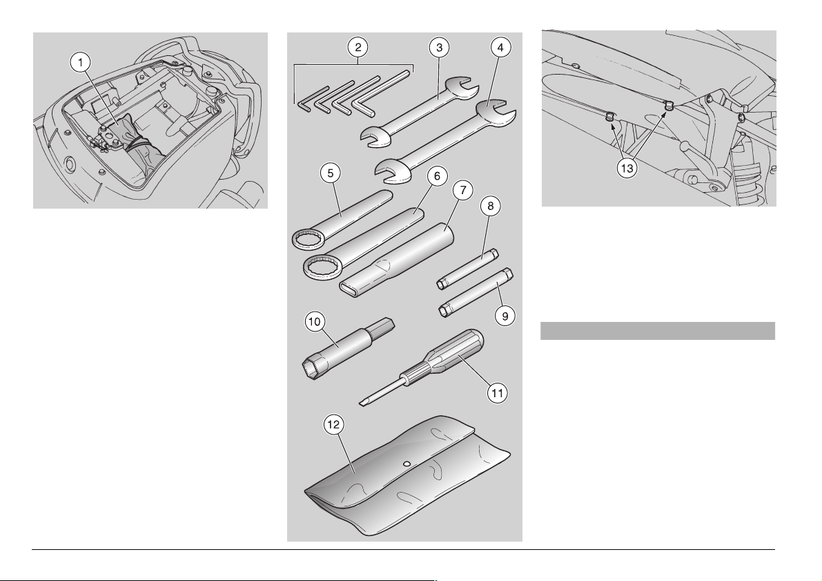
',/6%4//,+)4#/-0!24-%.4
The glove / tool kit compartment is positioned under the passenger seat; to reach
it, proceed as follows:
◆
Remove the passenger seat, see p. 27
(UNLOCKING / LOCKING THE PASSENGER SEAT).
The tool kit (1) includes:
– 3, 4, 5, 6 mm bent hexagon spanners (2)
– 8-10 mm double fork spanner (3)
– 11-13 mm double fork spanner (4)
– 22 mm simple box spanner (5)
– 32 mm simple box spanner (6)
– Extension for simple box spanners (7)
– 6-7 mm double socket spanner (8)
– 8-10 mm double socket spanner (9)
– 16 mm socket spanner for spark plug (10)
– Double-ended, cross-/cut-headed
screwdriver (11)
– Tool case (12)
Maximum allowed weight: 1.5 kg
use and maintenance SL mille
28
,5''!'%2!#+&!34%.).'3
Small luggage can be anchored to the passenger seat, by means of elastic bands
that must be fixed to the two fastenings
(13).
Maximum allowed weight: 9 kg.
aWARNING
The luggage must have reduced dimensions and must be anchored securely.
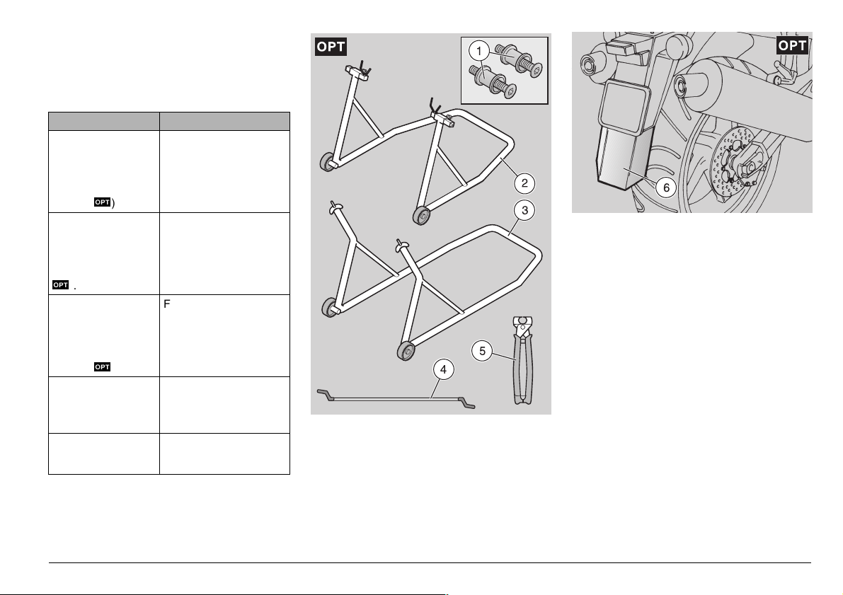
30%#)!,4//,3m
To perform some specific operations, it is
advisable to use the following special tools
(to be requested to an aprilia Official Dealer):
Tool Operations
Pins (1) for the rear
support stand, see p.
58 (ASSEMBLING
THE PINS FOR THE
REAR SUPPORT
STAND
m
).
Rear support stand
(2), see p. 58 (POSITIONING THE VEHICLE ON THE REAR
SUPPORT STAND
m
).
Front support stand
(3), see p. 58 (POSITIONING THE VEHICLE ON THE
FRONT SUPPORT
STAND
m
).
Fuel tank support rod
(4), see p. p. 66 (LIFTING THE FUEL
TANK).
Click clamp (5) installation pliers, see p. 54
(CLICK CLAMPS).
To position the vehicle on
the rear support stand
Engine oil and engine oil
filter change.
Rear wheel disassembly.
Drive chain adjustment.
Front wheel disassembly.
Lifting the fuel tank.
Click clamp installation.
2%!2-5$'5!2$%84%.3)/.m
The rear mudguard extension (6) can be
used when the road surface is wet, in fact it
reduces the reach of the water spray
caused by the rear wheel.
NOTE The rear mudguard extension (6)
is supplied as standard component in the
countries where this is required for the homologation.
use and maintenance SL mille
29
 Loading...