

Page 1

LONG INACTIVITY
OF THE BATTERY
If the vehicle remains unused for more than
fifteen days, it is necessary to recharge the
battery, in order to prevent its sulphation, see
page 75 (RECHARGING THE BATTERY).
It is important to check the charge periodically (about once a month), during the winter or when the vehicle remains unused, in
order to prevent the deterioration of the battery.
♦ Recharge it completely with a normal
charge, see page 75 (RECHARGING THE
BATTERY).
If the battery remains on the vehicle, disconnect the cables from the terminals.
CHECKING AND CLEANING
THE TERMINALS
Carefully read page 72 (BATTERY).
♦ Gain access to the battery, see page 74
(ACCESS TO BATTERY).
♦ Make sure that the cable terminals (1) and
the battery terminals (2) are:
– in good conditions (and not corroded or
covered with deposits);
– covered with special grease or Vaseline.
If necessary:
♦
Make sure that the ignition switch is in position
“ ”.
♦ Disconnect first the negative (–) and then
the positive cable (red) (+).
♦ Brush with a wire brush to eliminate any
sign of corrosion.
♦ Reconnect first the positive (red) (+) and
then the negative cable (–).
♦ Cover the terminals with special grease or
Vaseline.
♦ Refit the battery, see page 75 (INSTALL-
ING THE BATTERY).
use and maintenance
Scarabeo 50 - Scarabeo 100 4T
73
Page 2
100
MAX
1
MIN
1
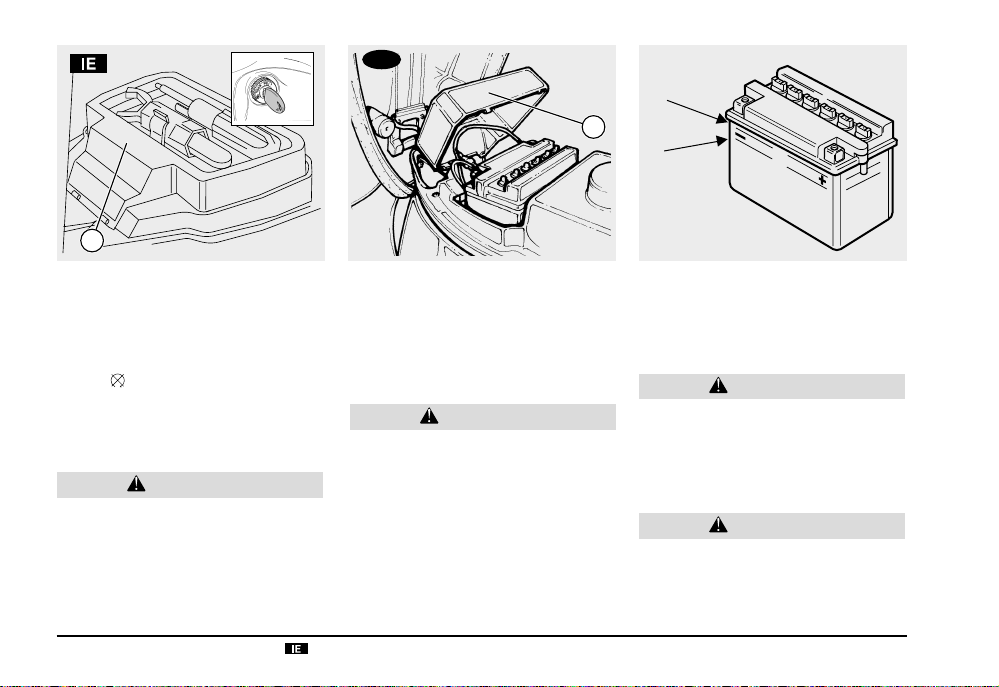
REMOVING THE BATTERY
Carefully read page 72 (BATTERY).
ACCESS TO BATTERY
♦ Make sure that the ignition switch is in po-
sition “
♦ Lift the saddle, see page 24 (UNLOCKING
♦ Remove the battery cover (1).
”.
/ LOCKING THE SADDLE).
CAUTION
The battery is connected to the electrical
wires. Do not force the wires while removing the battery.
use and maintenance
74
Scarabeo 50 - Scarabeo 100 4T
COMPLETE REMOVAL
♦ Disconnect first the negative (-) and then
the positive cable (red) (+).
♦ Detach the breather pipe.
♦ Remove the battery from its compartment
and put it on a flat surface, in a cool and
dry place.
WARNING
Once it has been removed, the battery
must be stored in a safe place and kept
away from children.
CHECKING
THE ELECTROLYTE LEVEL
Carefully read page 72 (BATTERY).
♦ Remove the battery (see REMOVING THE
BATTERY).
♦ Make sure that the fluid level is included
between the two “MIN” and “MAX” notches
stamped on the battery side.
Otherwise:
♦ Unscrew and remove the element plugs.
CAUTION
Top up with distilled water only.
Do not exceed the “MAX” mark, since the
electrolyte level increases during the recharge.
♦ Top up by adding distilled water.
CAUTION
After topping up, put back the element
plugs in the correct position.
♦ Put back the element plugs.
Page 3

RECHARGING THE BATTERY
Carefully read page 72 (BATTERY).
♦ Remove the battery, see page 74 (REMOV -
ING THE BATTERY).
♦ Take a suitable battery charger.
♦ Unscrew and remove the element plugs.
♦
Check the electrolyte level, see page 74
(CHECKING THE ELECTROLYTE LEVEL).
♦ Connect the battery with a battery charger.
NOTE A recharge with an amperage equal
to 1/10 th of the battery capacity is recommended.
♦ Switch on the battery charger.
♦ After the recharging operation, check the
electrolyte level again and if necessary top
up with distilled water.
♦ Tighten the element plugs.
CAUTION
Reassemble the battery only 5-10 minutes
after disconnecting the recharger, since
the battery continues to produce gas for
a short lapse of time.
INSTALLING THE BATTERY
Carefully read page 72 (BATTERY).
♦ Make sure that the ignition switch is in po-
sition “
”.
♦ Put the battery in its container.
♦ Connect the breather pipe.
CAUTION
Always connect the battery breather pipe,
to prevent the sulphuric acid vapours
from corroding the electric system,
painted parts, rubber elements or gaskets
when they exit the breather pipe itself.
The breather pipe must be connected in
such a way as not to be squashed, otherwise it may cause a pressure increase
inside the battery, with the risk of damaging it.
100
♦ Connect, in order, the positive (red) (+) and
negative (
♦ Cover the terminals with special grease or
-) cable.
Vaseline.
CAUTION
Upon reassembly, put the electrical cables in the correct position taking care
not to squash them.
The negative cable (
upon the positive cable (+). Take care to
position it on the side, between the battery and the box.
♦ Push the battery into the battery holder
♦ Close the battery cover (1).
♦ Lower the saddle, see page 24 (UNLOCK-
ING / LOCKING THE SADDLE).
-) must not be placed
use and maintenance
Scarabeo 50 - Scarabeo 100 4T
75
Page 4

3
1
CHANGING THE FUSES
Carefully read page 47 (MAINTENANCE).
CAUTION
Do not repair faulty fuses.
Never use fuses different from the recommended ones.
The use of unsuitable fuses may damage
the electric system or, in case of short
circuit, may even cause a fire.
NOTE If a fuse blows frequently, there prob-
ably is a short circuit or an overload in the
electric system.
In this case it is advisable to consult an
aprilia Official Dealer.
use and maintenance
76
Scarabeo 50 - Scarabeo 100 4T
If an electric component does not work or
works irregularly, or if the engine fails to start,
it is necessary to check the fuses (1).
To carry out the checking:
♦ Turn the ignition switch to position “ ”, to
avoid any accidental short circuit.
♦ Gain access to the battery in order to work
on the fuses, see page 74 (ACCESS TO
BATTERY).
♦ Extract the fuses (1) one by one and check
if the filament (2) is broken.
♦ Before replacing a fuse, try to find out the
cause of the trouble, if possible.
♦ Then replace the damaged fuse with a new
one having the same amperage.
NOTE If you use one of the spare fuses
(3), put a new fuse in the appropriate seat.
♦ Reposition the inspection cover, see page
65 (REMOVING THE INSPECTION
COVER).
LOCATION OF FUSES
7.5 A fuse (1) - From key switch to:
all electrical loads, other than the lights circuit that is powered with alternate current.
Page 5

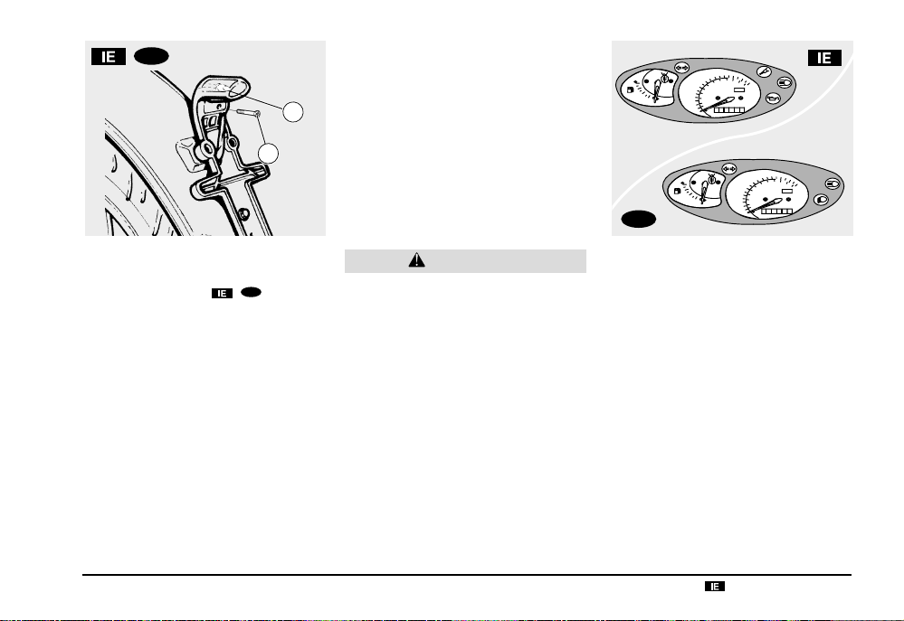
ADJUSTING THE VERTICAL
HEADLIGHT BEAM
NOTE To check the direction of the head-
light beam, specific procedures must be
adopted, in accordance with the regulations
in force in the country where the vehicle is
used.
To rapidly check the correct direction of the
beam, place the vehicle on flat ground, 10 m
away from a wall.
♦ Turn on the low beam, sit on the vehicle
and make sure that the beam projected on
the wall is slightly under the horizontal line
of the headlight (about 9/10th of the total
height).
1
To adjust the headlight beam:
♦ Position the vehicle on the centre stand,
on a solid and level surface.
♦ Act on the suitable screw (1) by means of
a screwdriver.
By TURNING IT CLOCKWISE, you set the
beam upwards.
By TURNING IT ANTICLOCKWISE, you
set the beam downwards.
BULBS
Carefully read pages 48-53 (REGULAR
SERVICE INTERVALS CHART).
WARNING
Risk of fire.
Keep fuel and other flammable substances away from the electrical components.
CAUTION
Before changing a bulb, position the vehicle on the centre stand, move the igni-
tion switch to position “
few minutes, so that the bulb cools down.
Change the bulb wearing clean gloves or
using a clean and dry cloth.
Do not leave fingerprints on the bulb,
since these may cause its overheating
and consequent breakage.
If you touch the bulb with bare hands,
remove any fingerprint with alcohol, in
order to avoid any damage.
DO NOT FORCE THE ELECTRIC CABLES.
” and wait a
use and maintenance
Scarabeo 50 - Scarabeo 100 4T
77
Page 6

1
2
CHANGING
THE HEADLIGHT BULBS
Carefully read page 77 (BULBS).
The headlight houses:
– one low / high beam bulb (1);
– one parking light bulb (2).
To change them:
♦ Remove the front handlebar cover, see
page 65 (REMOVING THE FRONT HANDLEBAR COVER).
use and maintenance
78
Scarabeo 50 - Scarabeo 100 4T
LOW / HIGH BEAM BULB
♦ Turn the bulb socket anticlockwise (3) and
remove it from its seat.
♦ Gently press and turn anticlockwise the
low/high beam bulb (1), remove it and replace it with one of the same type.
PARKING LIGHT BULB
CAUTION
Do not pull the electrical wires when removing the bulb socket.
♦ Get hold of the parking light bulb socket
(4), pull it and remove it from its seat.
♦ Withdraw the bulb (2) and replace it with
one of the same type.
Page 7

5
3
1
4
2
CHANGING THE FRONT
DIRECTION INDICATOR
BULBS
Carefully read page 77 (BULBS).
♦ Position the vehicle on the stand.
♦ Unscrew and remove the screw (1).
NOTE While removing the protection
screen, proceed carefully in order not to
break the cog.
♦ Remove the protection screen (2).
♦ Remove the amber yellow glass (3).
NOTE Upon reassembly, correctly position
the protection screen in its seat.
Tighten the screw (1) moderately and carefully, to avoid damaging the protection
screen.
6
♦ Press the bulb (4) slightly and rotate it an-
ticlockwise.
♦ Extract the bulb (4) from its seat.
7
6
NOTE Insert the bulb in the bulb socket,
making the two bulb pins coincide with the
relevant guides on the socket.
♦ Correctly install a new bulb of the same
type.
NOTE If the bulb socket (5) goes out of its
seat, insert it correctly, making the bulb socket
opening coincide with the screw seat.
CHANGING
THE REAR LIGHT BULB
Carefully read page 77 (BULBS).
♦ Position the vehicle on the stand.
♦ Unscrew and remove the two screws (6).
NOTE While removing the protection
screen, proceed carefully in order not to
break the cog.
♦ Remove the protection screen (7).
♦ Press the bulb slightly and rotate it anti-
clockwise.
♦ Remove the bulb from its seat.
NOTE Insert the bulb in the socket, mak-
ing the two bulb pins coincide with the relevant guides on the socket.
♦ Correctly install a new bulb of the same
type.
NOTE Upon reassembly, correctly position
the protection screen in its seat.
Tighten the screws (6) moderately and carefully, to avoid damaging the protection
screen.
use and maintenance
Scarabeo 50 - Scarabeo 100 4T
79
Page 8

6
1
1
2
CHANGING THE REAR
DIRECTION INDICATOR
BULBS
Carefully read page 77 (BULBS).
♦ Position the vehicle on the stand.
♦ Unscrew and remove the two screws (1).
NOTE While removing the protection
screen, proceed carefully in order not to
break the cog.
♦ Remove the protection screen (2).
NOTE Upon reassembly, correctly position
the protection screen in its seat.
♦ Remove the protection screen (3), by pull-
ing it to the vehicle external side.
use and maintenance
80
Scarabeo 50 - Scarabeo 100 4T
5
♦ Gently press on the amber yellow glass (4),
turn it anticlockwise and remove it.
4
3
NOTE While removing the protection
screen, proceed carefully in order not to break
the cog.
♦ Press the bulb (5) slightly and rotate it an-
ticlockwise.
♦ Extract the bulb (5) from its seat.
NOTE Insert the bulb in the bulb socket,
making the two bulb pins coincide with the
relevant guides on the socket.
♦ Correctly install a new bulb of the same
type.
NOTE If the bulb socket (6) goes out of its
seat, insert it correctly, making the bulb
socket opening coincide with the screw seat.
Page 9
100
70
80
60
90
50
40
4/4
1/2
R
1
50
30
40
aprilia
mph km/h
30
20
20
10
0 00 01000
0
Km
2
CHANGING THE NUMBER
PLATE BULB (in the countries
where required)
Carefully read page 77 (BULBS).
To change the bulb:
♦ Unscrew and remove the screw (1).
♦ Withdraw the rubber bulb socket (2).
♦ Remove the bulb from its seat.
♦ Correctly fit a new bulb following the same
operations in the reverse order.
100
CAUTION
To extract the bulb socket, do not pull the
electric wires.
NOTE Upon reassembly, make sure the
bulb socket is properly inserted in its seat.
use and maintenance
70
80
60
90
50
40
50
30
40
aprilia
mph km/h
30
20
20
10
0 00 01000
0
Km
100
4/4
1/2
R
CHANGING
THE DASHBOARD BULBS
Carefully read page 77 (BULBS).
The dashboard contains:
– the warning light bulbs;
– the dashboard lighting bulbs.
To change the bulbs:
♦ Remove the front handlebar cover, see
page 65 (REMOVING THE FRONT HANDLEBAR COVER).
Scarabeo 50 - Scarabeo 100 4T
81
Page 10
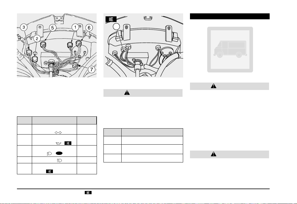
TRANSPORT
4
WARNING LIGHT BULBS
NOTE Extract the bulb sockets one by one,
in such a way as to avoid positioning them
incorrectly during the reassembly.
♦ Extract the relative bulb socket:
Pos. Warning light Colour
Direction
1
indicators (
2 stroke
2
oil reserve (
Low
2
beam (
High beam (
3
Injection
4
check
♦ Extract the bulb and replace it with one of
the same type.
use and maintenance
82
)
)
100
)
)
Scarabeo 50 - Scarabeo 100 4T
green
red
green
blue
red
DASHBOARD LIGHTING BULBS
CAUTION
Extract the bulb sockets one by one, in
such a way as to avoid positioning them
incorrectly during the reassembly.
♦ Extract the bulb socket of the dashboard
part in which there has been a light decrease:
Pos. Lit part
5 Upper right part
6 Upper left part (*)
7 Lower right part
(*) This bulb may not be installed on some
versions.
♦ Extract the bulb and replace it with one of
the same type.
WARNING
Before transporting the vehicle, it is necessary to empty the fuel tank and the carburettor completely, see page 83 (DRAINING THE FUEL TANK) making sure that
both are completely dry.
During transport the vehicle must be kept
in vertical position and be firmly anchored, in order to avoid any leakage of
fuel, oil or coolant.
WARNING
In case of failure, do not tow the vehicle,
but ask for assistance.
Page 11

DRAINING THE FUEL TANK
Carefully read page 27 (FUEL).
WARNING
Risk of fire.
Wait until the engine and the exhaust silencer have completely cooled down.
Fuel vapours are noxious for your health.
Before proceeding, make sure that the
room in which you are working is properly ventilated.
Do not inhale fuel vapours.
Do not smoke, nor use free flames.
DO NOT DISPOSE OF FUEL IN THE ENVIRONMENT.
♦ Position the vehicle on the centre stand,
on a solid and level surface.
♦ Stop the engine and wait until it has cooled
down.
♦ Prepare a container with capacity exceed-
ing the fuel quantity present in the tank
and put it on the ground on the left side of
the vehicle.
♦ Remove the fillercap.
♦ Empty the fuel tank by means of a manual
pump or a similar system.
WARNING
After draining the tank, put back the filler
cap in the correct position.
♦
Put back the filler cap.
4
1
T o drain the carburettor completely , proceed
as follows:
♦ Remove the hose clamp (4) from the right-
hand side of the vehicle.
♦ Position the tube free end (1) inside a con-
tainer.
100
♦ Open the passenger left-hand footrest (2).
♦ Insert a screwdriver between the footrest
and engine operating on the left-hand side
of the vehicle.
NOTE On reassembly, always replace the
clamp with a new one.
use and maintenance
♦ Open the carburettor outlet by loosening
the drain screw (3) positioned under the
float chamber.
When all the fuel has flowed out of the carburettor:
♦ Tighten the drain screw (3) completely.
WARNING
Tighten the drain screw (3) with care, to
avoid fuel leakages from the carburettor
during the refuelling.
If necessary, contact an aprilia Official
Dealer.
Scarabeo 50 - Scarabeo 100 4T
83
Page 12

CLEANING
Clean the vehicle frequently if it used in particular areas or conditions, such as:
♦ Polluted areas (cities and industrial areas).
♦ Areas characterized by an high percent-
age of salinity and humidity (sea areas, hot
and humid climates).
♦ Particular conditions (use of salt and anti-
ice chemical products on the roads during
the winter).
♦ Avoid leaving deposits of industrial and
polluting powders, tar spots, dead insects,
bird droppings, etc. on the body.
♦ Avoid parking the vehicle under trees, since
in some seasons residues, resins, fruits or
leaves fall down, which contain substances
that may damage the paint.
WARNING
After the vehicle has been washed, its
braking functions could be temporarily
impaired because of the presence of water on the grip surfaces. Calculate long
braking distances to avoid accidents.
Brake repeatedly to restore normal conditions.
Carry out the preliminary checking operations, see page 37 (PRELIMINARY
CHECKING OPERATIONS).
use and maintenance
84
Scarabeo 50 - Scarabeo 100 4T
To remove dirt and mud from the painted
surfaces use a low- pressure water jet, carefully wet the dirty parts, remove mud and filth
with a soft car sponge impregnated with a
lot of water and shampoo (2 – 4% parts of
shampoo in water).
Then rinse with plenty of water and dry with
chamois leather.
To clean the outer parts of the engine use a
degreaser, brushes and wipers.
CAUTION
To clean the lights, use a sponge soaked
with water and a neutral detergent, rubbing the surfaces delicately and rinsing
frequently with plenty of water.
Polish with silicone wax only after having carefully washed the vehicle. Do not
wash the vehicle under the sun, especially
during the summer, when the body is still
warm, since if the shampoo dries before
being rinsed away, it can damage the
paint.
Do not use liquids at a temperature exceeding 40°C to clean the plastic components of the vehicle.
CAUTION
Do not direct high-pressure water or air
jets or steam jets on to the following components: wheel hubs, controls on the
right and left side of the handlebar, bearings, brake pumps, instruments and indicators, exhaust pipes, glove/tool kit
compartment, ignition switch/steering
lock, radiator wings, fuel cap, lights and
electric connections.
Do not use alcohol or solvents to clean
the rubber and plastic parts and the saddle: use water and mild soap.
WARNING
Do not apply protection waxes onto the
saddle, in order not to make it too slippery.
Page 13

LONG PERIODS OF INACTIVITY
Precautions are needed to avoid the adverse
effects of prolonged inactivity.
Further, it is important to carry out the necessary repairs and a general check up before the period of inactivity, since you could
forget to carry them out later.
Proceed as follows:
♦
Completely drain the tank and carburettor,
see page 83 (DRAINING THE FUEL
TANK).
♦
R
emove the spark plug, see page 71
(SPARK PLUG) and pour one teaspoon (5-
3
) of oil for two-stroke engines in the
10 cm
cylinder.
NOTE Put a clean cloth on the cylinder,
next to the spark plug seat, as a protection
against oil splashes.
♦ Turn the ignition switch to “ ” and press
the engine start button “
onds to distribute the oil evenly on the cyl-
inder surfaces.
♦ Remove the cloth.
♦ Refit the spark plug.
♦ Remove the battery, see page 74 (REMOV -
ING THE BATTERY).
♦ Wash and dry the vehicle, see page 84
(CLEANING).
♦
Polish the painted surfaces with wax.
” for a few sec-
♦ Inflate the tyres, see page 34 (TYRES).
♦ By means of a suitable support, position
the vehicle so that both tyres are raised
from the ground.
♦ Place the vehicle in an unheated, not-hu-
mid room, away from sunlight, with minimum temperature variations.
♦ Position and tie a plastic bag on the final
pipe of the exhaust silencer, in order to prevent moisture from getting into it.
♦ Cover the vehicle avoiding the use of plas-
tic or waterproof materials.
AFTER A PERIOD OF INACTIVITY
♦ Uncover and clean the vehicle, see page
84 (CLEANING).
♦ Check the charge of the battery, see page
75 (RECHARGING THE BATTERY) and
install it, see page 75 (INSTALLING THE
BATTERY).
♦ Check that the carburettor drain screw is
fully tightened (drainage closing index), see
page 83 (DRAINING THE FUEL TANK).
♦ Refuel, see page 27 (FUEL).
♦ Carry out the preliminary checking opera-
tions, see page 37 (PRELIMINARY
CHECKING OPERATIONS).
WARNING
Have a test ride at moderate speed in a
low-traffic area.
use and maintenance
Scarabeo 50 - Scarabeo 100 4T
85
Page 14

TECHNICAL DATA
100
100
100
DIMENSIONS Max. length ........................................................
ENGINE Model .................................................................
Max. width (brake levers)...................................
Max. height (rearview mirrors) ...........................
Seat height.........................................................
Wheel base ........................................................
Minimum free height from ground ......................
Empty weight (in running order).........................
Type ...................................................................
Number of cylinders ........................................... Horizontal single-cylinder
Total displacement .............................................
Bore / stroke ...................................................... 41.0 mm / 37,4 mm -
Compression ratio..............................................
Starting ..............................................................
Clutch................................................................. centrifugal
Change gear ...................................................... automatic continuous variator
Change gear ...................................................... ventilated automatic continuous variator
Cooling............................................................... forced air
TRANSMISSION Variator .............................................................. automatic continuous
Primary .............................................................. V belt
Ratios................................................................. minimum for continuous change:
maximum for continuous change:
Secondary.......................................................... with gears
CAPACITY Fuel (reserve included) ...................................... 8
use and maintenance
86
Fuel reserve ....................................................... 1
Transmission oil .................................................
Engine oil ...........................................................
Mixer oil (reserve included)................................
Mixer oil reserve ................................................
Seats.................................................................. n° 1 (2 in the countries where this is allowed)
Seats.................................................................. n° 2
Vehicle max. load (driver + luggage) ................. 110 kg
Vehicle max. load (driver + passenger + luggage)
Scarabeo 50 - Scarabeo 100 4T
100
185 kg (in the countries where this is allowed)
1905 mm 705 mm 1270 mm 780 mm 1250 mm 145 mm 86 kg -
100
2T -
4T
ABAI -
49.38 cm3 -
10.5:1 electric -
120 cm3 -
0.8 l
1.5
0.6
100
100
1905 mm
100
705 mm
100
1270 mm
100
780 mm
100
1245 mm
100
140 mm
94 kg
4T2V
100
96.21 cm
100
100
100
10.5:1
100
electric + kick starter
3
100 cm
3
50 mm / 49 mm
2.90 -
0.75 -
100
2.63
0.76
Page 15

CARBURETTOR Model:
– standard ..........................................................
Choke tube ........................................................
FUEL SUPPLY Fuel
100
..................................................... premium petrol DIN 51 600 (4 Stars), minimum octane number 98
100
KEIHIN CVK 20 - DELLORTO PHVD 22
throttle body BING Ø 18 mm -
100
Ø 20 mm / Ø 22 mm
(N.O.R.M.) and 88 (N.O.M.M.)
FRAME Type ................................................................... split single tube with double cradle
SUSPENSIONS Front................................................................... hydraulically operated telescopic fork
Stroke ................................................................ 80 mm
Rear ................................................................... hydraulic single-shock absorber
Stroke ................................................................
78 mm -
100
82 mm
BRAKES Front................................................................... disc brake, Ø220 mm with hydraulic transmission
Rear ............................................................ disc brake, Ø190 mm with hydraulic transmission
100
Rear
............................................................ Ø 140 mm
WHEEL Rims................................................................... alloy
Front................................................................... 1.60 x 16"
Rear ................................................................... 1.85 x 16"
TYRES Front...................................................................
Rear ...................................................................
2.50 x16” 42J SAVA MC 26 CAPRI 46M
REINF
2.75 x 16” 46J SAVA MC 26 CAPRI 52 M
REINF
100
80 / 80 x 16”
100
90 / 80 - 16”
STANDARD INFLATION PRESSURE
Front................................................................... 190 kPa (1.9 bar)
Rear ................................................................... 220 kPa (2.2 bar)
INFLATION PRESSURE WITH PASSENGER (in the countries where this is allowed)
Front................................................................... 190 kPa (1.9 bar)
Rear ................................................................... 230 kPa (2.3 bar)
use and maintenance
Scarabeo 50 - Scarabeo 100 4T
87
Page 16

IGNITION Type ................................................................... T.C.I. -
100
Spark advance
Spark advance
Standard spark plug...........................................
............................................ variable con 20° at 4000 rpm
100
............................................ 17° at 7500 rpm
NGK CPR 8E -
Spark plug gap................................................... 0.6 ± 0.05 mm
rpm at slow running ........................................... 1900+o-50
C.D.I.
100
NGK BR8 HS
ELECTRIC
SYSTEM Battery ............................................................... 12 V - 4 Ah (sealed
Fuse ................................................................... 7.5 A
Generator (with permanent magnet)..................
Low / high beam bulbs ....................................... 12 V - 35 / 35 W
Parking light bulb ............................................... 12 V - 5 W (W 2.1 x 9.5 d)
Direction indicators bulbs................................... 12 V - 10 W
Stop/tail light bulb .............................................. 12 V - 5/21 W
Number plate bulb ............................................. 12 V - 5 W
Dashboard lighting bulb ..................................... 12 V - 1.2 W
High beam warning lights .................................. 12 V - 1.2 W
Direction indicators warning lights ..................... 12 V - 3 W
Mixer oil reserve warning light ........................... 12 V - 1.2 W
Injection check warning light .............................. 12 V - 2 W
use and maintenance
88
Scarabeo 50 - Scarabeo 100 4T
12 V - 140 W /
) - 12 V - 9 Ah
100
13 V - 120 W
100
Page 17

use and maintenance
Scarabeo 50 - Scarabeo 100 4T
89
Page 18

LUBRICANT CHART
Engine oil (recommended): SUPERBIKE 4, SAE 5W - 40.
As an alternative to the recommended oil, it is possible to use high-quality oils with characteristics in compliance with or superior to CCMC G4, A.P.I. SG. specifications.
WARNING
In case of severe driving conditions or use of the vehicle in warm climates, it is recommended to use synthetic oil of the 5W50/
Transmission oil (recommended):
As an alternative to the recommended oil, it is possible to use high-quality oils with characteristics in compliance with or superior to the A.P.I.
GL-4 specifications.
Mixer oil (recommended):
As an alternative to the recommended oil, use high-quality oils with characteristics in compliance with or superior to the ISO-L-ETC++, A.P .I.
TC++ specifications.
Fork oil (recommended):
If you need an oil with intermediate characteristics in comparison with the F.A. 5W and F.A. 20W or FORK 5W and FORK
20W, these can be mixed as indicated below:
SAE 10W =
SAE 15W = F.A. 5W 33% of the volume + F.A. 20W 67% of the volume, or
Bearings and other lubrication points (recommended):
As an alternative to the recommended product, use high-quality grease for rolling bearings, working temperature range -30°C.... +140°C,
dripping point 150°C... 230°C, high protection against corrosion, good resistance to water and oxidation.
Protection of the battery poles: neutral grease or vaseline.
F.A. 5W 67% of the volume + F.A. 20W 33% of the volume, or
FORK 5W 67% of the volume + FORK 20W 33% of the volume;
FORK 5W 33% of the volume + FORK 20W 67% of the volume.
F.C., SAE 75W - 90 or GEAR SYNTH, SAE 75W - 90.
GREEN HIT 2 or CITY 2T.
F.A. 5W or F.A. 20W fork oil;
an alternative FORK 5W or FORK 20W fork oil.
10W50 type.
AUTOGREASE MP or GREASE 30.
WARNING
Brake fluid (recommended):
F.F., DOT 5 (DOT 4 compatible) or BRAKE 5.1, DOT 5 (DOT 4 compatible).
Use new brake fluid only.
WARNING
Engine coolant (recommended):
use and maintenance
90
Use only antifreeze and anticorrosive without nitrite, ensuring protection at -35°C at least.
ECOBLU - 40°C or COOL.
Scarabeo 50 - Scarabeo 100 4T
Page 19

NOTE
ASK FOR GENUINE SPARE PARTS ONLY
use and maintenance
Scarabeo 50 - Scarabeo 100 4T
91
Page 20

Importers
use and maintenance
92
Scarabeo 50 - Scarabeo 100 4T
Page 21

Importers
use and maintenance
Scarabeo 50 - Scarabeo 100 4T
93
Page 22

WIRING DIAGRAM - Scarabeo
1
41
N
BBB
N
42
Bi
B
1
N
43
use and maintenance
94
40
38
37
GBBBiAz
B
ViGBBiR
G
Vi
B
B
1
M
2
G/R
3
N
4
5
6
G
7
8
V/R
9
Bi
10
11
12
Bi/R
13
V
14
R/M
15
Ro
16
R/N
17
M/G
18
Bi/G
19
B/G
20
Ar/N
21
22
35
36
-C
+
V/R
B
R
Gr/V
V/R
Gr/V
AzAz
1
Gr/VBiR
V/R
Ar/N
B
V/R
39
Vi
1
Az
B
B
R
2
3
33
34
32
Gr/V
B
1
R/N
N
V/R
Gr/V
B
31
29
ON
OFF
LOCK
N
1
NBiG
Gr
BRB/N
Gr
30
G
B/NRBiBGr
Az
Az
B/N
V/R
Ar
1
L
B
V/R
Ar
R/N
28
26
27
G/RG/RVG
V/RV/G
M
1
1
Ro
G
V
1
G/R
Vi
V/R
Vi
23
Az
Az
V/G
V/G
G
G
B
R
V/G
R/N
V/G
R/N
21
22
R/M
11
Bi/ViBi/Vi
Bi/G
B/G
GBiRo
M/G
1
Bi
B
5
R/N
M
V/R
Ro
6 87 9104
R/M
R/M
Bi/R
G/R
12
B
G/R
15
Ar
R/N
V/R
1 2
R
3
5
Ar
R/N
V/R
R/N
V
13
P
R
15 A
1
7.5 A
R
R
R
N
M
16
14
N
ArBR/M
R/N
17
ARANCIO BIANCO
Ar/Bi
VISTO DAL LATO CHE
SI CONNETTE AL REGOLATORE
Ar/Bi
VBAr
11
Ar
G V
18
BLU
VERDEARANCIO
19
24
B
R
1
25
Ro Ro
20
Scarabeo 50 - Scarabeo 100 4T
Page 23

WIRING DIAGRAM KEY - Scarabeo
1) Multiple connectors
2) Electronic control unit (ECU)
3) Serial connection
4) Throttle sensor
5) Pick-up
6) Temperature sensor
7) Oil pump
8) Fuel injector
9) Air injector
10) Fuel pump
11) H.T. coil
12) Spark plug
13) Fuse
14) Battery
15) Start relay
16) Starter
17) Injection relay
18) Voltage regulator
19) Generator
20) Resistor
21) Front stoplight switch
22) Rear stoplight switch
23) Rear left direction indicator
24) Rear stoplight
25) Rear right direction indicator
26) Oil level switch
27) Control diode
28) RH switch
29) Key switch
30) Flashers
31) LH switch
32) Horn
33) Fuel level sensor
34) Injection check warning light
35) Fuel level instrument
36) Direction indicator warning light
37) High beam warning light
38) Dashboard light
39) Oil reserve warning light
40) Dashboard
41) Front left direction indicator
42) Low/high beam bulb (35/35W)
43) Front right direction indicator
CABLE COLOURS
Ar orange
Az light blue
B blue
Bi white
G yellow
Gr grey
M brown
N black
R red
V green
Vi violet
Ro pink
use and maintenance
Scarabeo 50 - Scarabeo 100 4T
95
Page 24

WIRING DIAGRAM - Scarabeo
30 27
252629
23
N
B
RAzBiBB
G
Bi
Az
R
BGV/R
NN
Bi
Az
G
R
38
N
Az
B
32
34
33
31
B
Bi
Bi
N
N
B
B
G
G
38
B
B
N
R
35
B
M
G/Bi
Gr
V/R
38
N
M
36
1
100
C-
+
V/R
B
Gr/V
Gr/V
38
Gr/V
V/R
G/Bi
Bi/R
B
M
4312
2
3
19
ON
OFF
LOCK
V/R
ArBBi/R
38
V/R
BArBi/R
Bi/R
Gr/V
Bi
N
Az
G
B
R
V/R
Gr
G/Bi
B
V
V/R
V
B
B/N
G/Bi
38
5
3
4
38
12
V
G
5
40 6
GrGr
N
G/N
B
BiRB/NB/N
NBiG/N
Az Az
R
B
B
G/R
8
R
Ar
37
7.5 A
N
R
R
V/G
V/R
R
9
V/G
V/R
R
10
M
7
3838
V
G/N G/N
V
GG
B
Gr/V
38
B
Gr/V
13
17
M
G/R G/R
V/G V/R
16
Az
Az
V/G
V/G
G
G
B
R
38
G
B
38
G
B
15
B
R
14
12
use and maintenance
96
Scarabeo 50 - Scarabeo 100 4T
Page 25

WIRING DIAGRAM KEY - Scarabeo
100
1) Generator
2) Transducer
3) Spark plug
5) Voltage regulator
6) Battery
7) Starter
8) Start relay
9) Front stoplight switch
10) Rear stoplight switch
12) Number plate bulb
13) Fuel level sensor
14) Rear right direction indicator
15) Rear stoplight
16) Rear left direction indicator
17) RH switch
18) LH switch
19) Key switch
23) Dashboard
25) Low beam warning light
26) Dashboard light
27) Fuel level instrument
29) High beam warning light
30) Direction indicator warning light
31) Front right direction indicator
32) Front left direction indicator
33) Parking lights bulb
34) Low / high beam bulb (35/35W)
35) Horn
36) Pick up
37) Fuse
38) Multiple connectors
40) Automatic starter
CABLE COLOURS
Ar orange
Az light blue
B blue
Bi white
G yellow
Gr grey
M brown
N black
R red
V green
Vi violet
use and maintenance
Scarabeo 50 - Scarabeo 100 4T
97
Page 26

NOTE
ASK FOR GENUINE SPARE PARTS ONLY
use and maintenance
98
Scarabeo 50 - Scarabeo 100 4T
Page 27

NOTE
ASK FOR GENUINE SPARE PARTS ONLY
use and maintenance
Scarabeo 50 - Scarabeo 100 4T
99
Page 28

NOTE
ASK FOR GENUINE SPARE PARTS ONLY
use and maintenance
100
Scarabeo 50 - Scarabeo 100 4T
Page 29

NOTE
ASK FOR GENUINE SPARE PARTS ONLY
use and maintenance
Scarabeo 50 - Scarabeo 100 4T
101
Page 30

NOTE
ASK FOR GENUINE SPARE PARTS ONLY
use and maintenance
102
Scarabeo 50 - Scarabeo 100 4T
Page 31

NOTE
ASK FOR GENUINE SPARE PARTS ONLY
use and maintenance
Scarabeo 50 - Scarabeo 100 4T
103
Page 32

aprilia s.p.a. wishes to thank its customers for the purchase of this vehicle.
- Do not dispose of oil, fuel, polluting substances and components in the
environment.
- Do not keep the engine running if it isn’t necessary.
- Avoid disturbing noises.
- Respect nature.
use and maintenance
104
Scarabeo 50 - Scarabeo 100 4T
 Loading...