

Page 1
MAIN INDIPENDENT CONTROLS
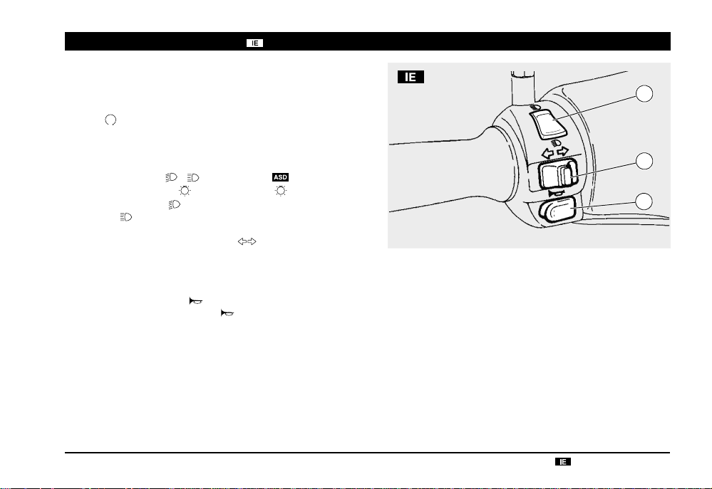
CONTROLS ON THE LEFT SIDE OF THE
HANDLEBAR
NOTE The electrical parts work only when the ignition switch is in
position “
”.
NOTE The lighting system works only when the engine is run-
ning.
1) DIMMER SWITCH (
When the light switch (
switch is in position "
position "
2) DIRECTION INDICATOR SWITCH (
To indicate the turn to the left, move the switch to the left; to
indicate the turn to the right, move the switch to the right.
To turn off the direction indicator, press the switch.
3) HORN PUSH BUTTON (
The horn is activated when the “
", the high beam comes on.
- ) (not provided )
- •) is in position " ", if the dimmer
", the low beam comes on; while if it is in
)
)
“ push button is pressed.
1
2
3
use and maintenance
Scarabeo 50 - Scarabeo 100 4T
19
Page 2

1
use and maintenance
20
CONTROLS ON THE RIGHT SIDE OF THE
1a
HANDLEBAR
NOTE The electrical parts work only when the ignition switch is in
position “
”.
NOTE The lighting system works only when the engine is run-
ning.
-
1) LIGHT SWITCH (
)
•
NOTE Before operating the light switch, make sure that the
dimmer switch (
2
When the light switch is in position “
position “
or high beam are on.
The low or high beam can be operated by means of the dimmer
switch (
1a) DIMMER SWITCH ( - )
When the dimmer switch is in position “ ”, the low beam, the
parking and the dashboard lights are on; when it is in position
”, the high beam, the parking and the dashboard lights are on.
“
- ) is in position “ ”.
”, the lights are off; in
“, the parking lights, the dashboard light and the low
- ).
•
NOTE The lights can be switched off only by stopping the en-
gine.
2) START PUSH BUTTON (
When the start push button is pressed and one of the brake
levers (front or rear) is activated at the same time, the starter
makes the engine run.
For the starting, see page 38 (STARTING).
Scarabeo 50 - Scarabeo 100 4T
)
Page 3

MAIN INDIPENDENT CONTROLS
100
CONTROLS ON THE LEFT SIDE OF THE
HANDLEBAR
NOTE The electrical parts work only when the ignition switch is in
position “
”.
NOTE The lighting system works only when the engine is running.
1) DIMMER SWITCH (
When the light switch (
switch is in position "
position "
2) DIRECTION INDICATORS DISABLING BUTTON (▲)
Move the direction indicator switch (3) to the right or to the left and
press the button to disable the direction indicators operation.
3) DIRECTION INDICATOR SWITCH ( )
T o indicate the turn to the left, move the switch to the left; to indicate
the turn to the right, move the switch to the right.
To turn off the direction indicator, press the switch (2).
4) HORN PUSH BUTTON (
The horn is activated when the “
", the high beam comes on.
- )
- - •) is in position " ", if the dimmer
", the low beam comes on; while if it is in
)
“ push button is pressed.
100
use and maintenance
Scarabeo 50 - Scarabeo 100 4T
1
2
3
4
21
Page 4

100
CONTROLS ON THE RIGHT SIDE OF THE
HANDLEBAR
NOTE The electrical parts work only when the ignition switch is in
1
position “
”.
NOTE The lighting system works only when the engine is running.
1) LIGHT SWITCH ( - - •)
NOTE Before operating the light switch, make sure that the dim-
2
mer switch (
When the light switch is in position “
tion “
position “
light are on.
The low or high beam can be operated by means of the dimmer
switch (
- ) is in position “ ”.
”, the lights are off; in posi-
“, the parking lights and the dashboard light are on; in
“, the parking lights, the dashboard light and low beam
- ).
•
use and maintenance
22
Scarabeo 50 - Scarabeo 100 4T
3) START PUSH BUTTON (
When the start push button is pressed and one of the brake levers (front or rear) is activated at the same time, the starter makes
the engine run.
For the starting, see page 38 (STARTING).
)
Page 5

Position
Function
Key
removal
IGNITION SWITCH
The ignition switch is positioned on the right
side, near the steering column.
NOTE The key (1) operates the ignition/
steering lock switch, the tool kit compartment
lock and the saddle lock.
Two keys are supplied together with the vehicle (one spare key).
NOTE Do not keep the spare key on the
vehicle.
1
STEERING LOCK
WARNING
Never turn the key to position “ ” in running conditions, in order to avoid losing
control of the vehicle.
OPERATION
To lock the steering:
♦ Turn the handlebar completely leftwards.
♦
Turn the key (1) to position “ ” and press it.
♦ Release the key.
NOTE Turn the key and steer the handle-
bar at the same time.
♦ Rotate the key (1) anticlockwise (left-
wards), steer the handlebar slowly until the
key (1) reaches position “
♦ Extract the key.
”.
use and maintenance
The steering
is locked. It is
neither pos-
lock
sible to start
the engine,
nor to switch
on the lights.
Neither the
engine, nor
the lights can
be switched
on.
The engine
and the lights
can be
switched on.
Steering
Scarabeo 50 - Scarabeo 100 4T
It is possible
to remove
the key.
It is possible
to remove
the key.
It is not possible to remove the
key.
23
Page 6

AUXILIARY EQUIPMENT
2
1
3
4
5
UNLOCKING / LOCKING THE
SADDLE
To unlock and lift the saddle:
♦ Position the vehicle on the centre stand,
on a solid and level surface.
♦ Insert the key in the saddle lock (1).
♦ Turn the key clockwise and raise the sad-
dle (2).
NOTE Before lowering and locking the
saddle, make sure that you have not left the
key in the undersaddle.
♦
To lock the saddle, lower and press it at
the centre.
WARNING
Before leaving, make sure that the saddle is properly locked.
use and maintenance
24
Scarabeo 50 - Scarabeo 100 4T
DOCUMENT HOLDER
To open the document holder:
♦ Position the vehicle on the centre stand on
a solid and level surface.
♦ Insert the ignition key in the lock (3) and
turn it in a clockwise direction.
To close the document holder:
♦ Insert the ignition key, turn it in a clockwise
direction while pushing it, then turn the key
in the opposite direction to lock the document holder.
♦ Remove the key and check that the docu-
ment holder is closed.
WARNING
Do not overload the document holder.
Maximum allowed weight: 1.5 kg.
ANTI-THEFT HOOK
The anti-theft hook (4) is positioned on the
right side of the vehicle.
To prevent the vehicle from being stolen, it
is advisable to secure it with the aprilia
“Body-Guard” armored cable
able at any aprilia Official Dealer.
(5), avail-
WARNING
Do not use the hook to lift the vehicle or
for any purpose other than securing the
vehicle once it has been parked.
 Loading...