


READ AND SAVE THESE INSTRUCTIONS
Safety &
Installation
Instructions
TABLE OF CONTENTS
INSTALLATION |
|
|
POWER & RESET OPTIONS |
|
|
Thermostat installation location recommendations . . |
. 2 |
|
Power and reset options . . . . . . . . . . . . . . . . . . |
. . . 10. . |
|
Thermostat mounting . . . . . . . . . . . . . . . . . . . . . . . . . . |
. 2 |
|
|
|
|
|
SETUP & TESTING |
|
|||
Equipment control module installation location |
|
|
|
||
|
|
|
|
|
|
recommendations . . . . . . . . . . . . . . . . . . . . . . . . . . . . . |
. 2 |
|
Installer setup wizard . . . . . . . . . . . . . . . . |
. . 10. . . . . . . |
|
Equipment control module mounting . . . . . . . . . |
2. |
. . . . |
HVAC installer system settings tables . . . . . . . |
.10. -12 |
|
Thermostat wiring . . . . . . . . . . . . . . . . . . . . . . . . . . |
. 3. |
. |
General system settings table . . . . . . . . . . . . . . |
. . . 10 |
|
Remote temperature sensor (optional) . . . . . . . . . . . |
. 3. |
|
Thermostat system settings table . . . . . . . . . . . |
11-12 |
|
Equipment control module wiring . . . . . . . . . . . . . . . . |
. 4 |
|
Indoor Air Quality system settings tables . . . . . . . |
13-15 |
|
Outdoor temperature sensor (included) . . . . . . . . . . . . |
. 5 |
|
Humidifier system settings table . . . . . . . . . . . . . |
. . 13 |
|
Optional wireless outdoor temperature sensor . . . |
. 5. |
. |
Dehumidifier system settings table . . . . . . . . . . . |
. . 14 |
|
Return air temperature sensor (optional) . . . . . . . . |
.6 . |
. |
Air cleaning system settings table . . . . . . . . . . . . |
. . 14 |
|
Leaving air temperature sensor (optional) . . . . . . |
. 6. |
. . |
Fresh air system settings table . . . . . . . . . . . |
. .15. . . |
|
|
|
|
Installer system test |
16 |
|
HVAC WIRING DIAGRAMS |
|
||||
|
|
Wi-Fi setup |
|
16 |
|
|
|
|
. . . . . . . . . . . . . . . . . . . . . . . . . . . . . . . . |
||
Conventional heat/cool single transformer |
7 |
|
|||
|
|
|
|
||
Conventional heat/cool two transformer . . . . . . . |
. 7. |
. . |
REFERENCES |
|
|
. . . . . . . . . . . . . . . . . . .Heat pump single transformer |
. 8 |
|
Quick reference to controls & display . . . . . . . . . . |
17-18 |
|
Heat pump two transformer . . . . . . . . . . . . . . . |
.8. |
. . . |
Thermostat. |
features . . . . . . . . . . . . . . . . |
. . 18. . . . . . . |
|
|
|
Troubleshooting |
19. |
|
INDOOR AIR QUALITY WIRING DIAGRAMS |
|
||||
|
|
Specifications . . . . . . . . . . . . . . . . . . . . . . . . . . . . . . |
20. . |
||
|
|
|
|||
Indoor Air Quality wiring with separate transformers . . . 9
Indoor Air Quality wiring with a single transformer . . . . . 9
INSTALLATION
THERMOSTAT INSTALLATION LOCATION RECOMMENDATIONS
Thermostat should be mounted:
•On an interior wall, in a frequently occupied space..
•Approximately 5‘ above floor..
•At least 18” from outside wall..
•Thermostat can be mounted to a vertical junction box..
Do not mount thermostat:
•Behind doors, in corners or other dead air spaces..
•In direct sunlight, near lighting fixtures, or other appliances that give off heat..
•On an outside or unconditioned area wall..
•In the flow of a supply register, in stairwells, or near outside doors..
•On a wall with concealed pipes or ductwork..
THERMOSTAT MOUNTING
1. Remove the rear mounting plate from the thermostat..
2.Pull wires through the opening on the rear mounting plate..
3.Position and level the mounting plate of the thermostat on wall and mark the hole locations with a pencil..
4.Drill 1/4” holes and insert supplied anchors (drywall only)..
5.Place mounting plate over anchors, insert and tighten screws..
6. Seal wire entry holes to prevent drafts affecting temperature readings.. |
90-2122 |
|
EQUIPMENT CONTROL MODULE INSTALLATION LOCATION RECOMMENDATIONS
Note: Installer must touch a grounded metal object before handling the equipment control module to avoid potential damage due to electrical discharge..
Equipment control module should be mounted: |
Do not mount equipment control module: |
• In a location where the temperature will not exceed |
• On foundation walls or on the HVAC equipment or |
158°F (70°C) or drop below 32°F (0°C).. |
ductwork.. These locations can cause moisture to |
|
condense on the equipment control module.. |
EQUIPMENT CONTROL MODULE MOUNTING
The equipment control module has the following features to simplify mounting and wiring and provide for a clean and neat installation..
•Six (6) mounting holes.. One on each corner and two centered top and bottom.. Any combination of these holes may be utilized.. Mount the equipment control module using 2 to 4 #8 screws appropriate for the mounting surface substrate.. (See Figure 2..)
•Wires can be routed through the top, bottom, sides or back..
•Nylon wire ties can be used to secure wires in 10 places..
Installation Steps
1.Select mounting location..
2.Pull from bottom to remove front cover.. (See Figure 1..)
3.Mount base using 2 to 4 #8
screws (field supplied).. |
Figure 1 |
Figure 2 |
|
INSTALLATION
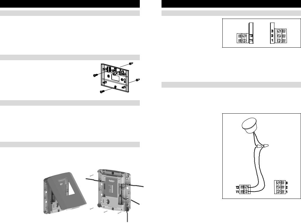
THERMOSTAT WIRING
Wire specifications: |
|
|
18-24 gauge thermostat wire |
|
|
Installation notes: |
|
|
• Ensure power at the HVAC equipment is off.. |
|
|
• Loosen screw terminals, insert stripped wire |
90-2123 |
|
and re-tighten.. |
||
|
||
• Push the excess wire back into the opening and plug the wall opening to prevent drafts.. |
|
1 – Connection to terminal 1 at equipment control module 2 – Connection to terminal 2 at equipment control module 3 – Connection to terminal 3 at equipment control module T1 & T2 – Remote temperature sensor (optional)
REMOTE TEMPERATURE SENSOR (OPTIONAL)
A remote temperature sensor can be used for control if the thermostat is to be mounted in a concealed location or a remote sensor can be averaged with the thermostat sensor to control a large space.. An 8051 flush mount or 8053 surface mount remote temperature sensor can be attached to the T1 and T2 terminals and mounted in a
recommended area.. The remote sensor must be enabled in the installer setup menu, and once enabled will override or be averaged with the thermostat’s internal temperature sensor, based on the setting..
Remote temperature sensor should be mounted:
•On an interior wall, in a frequently occupied space..
•Approximately 5‘ above floor..
•At least 18” from outside wall..
•Using less than 300’ of wire..
Do not mount remote sensor:
•Behind doors, in corners or other dead air spaces..
•In direct sunlight, near lighting fixtures, or other appliances that give off heat..
•On an outside or unconditioned area wall..
•In the flow of a supply register, in stairwells, or near outside doors..
•On a wall with concealed pipes or ductwork..
•Near 120 VAC lines..
90-2124
2 |
3 |
INSTALLATION
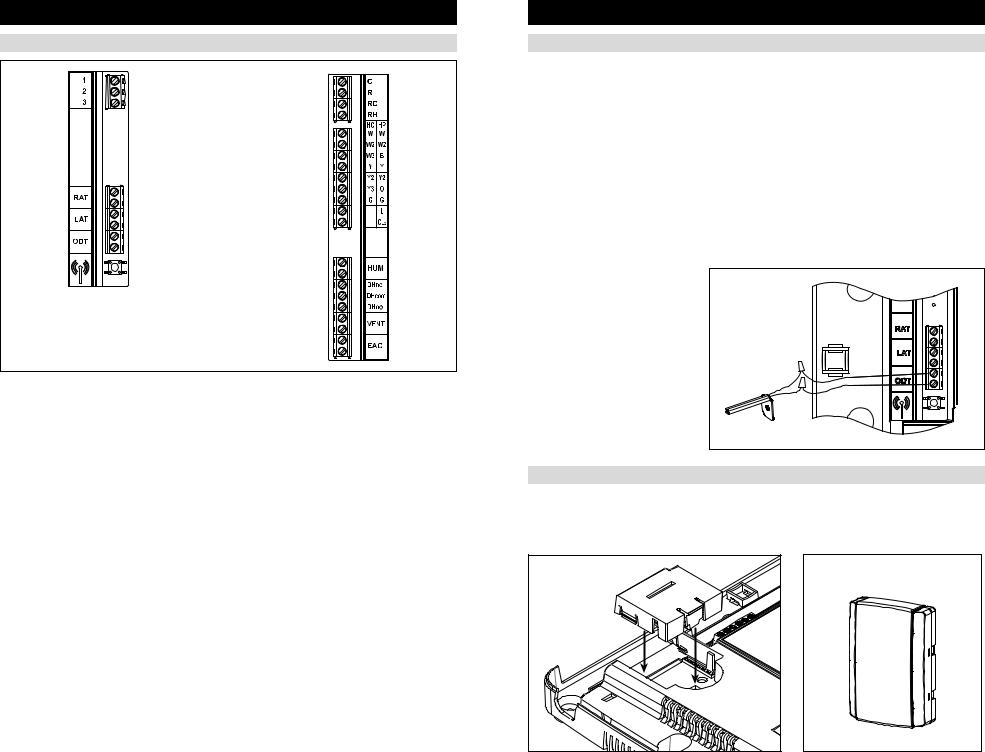
EQUIPMENT CONTROL MODULE WIRING
Wire specifications:
18-24 gauge thermostat wire
Installation notes:
•Ensure power at the HVAC equipment is off..
•Loosen screw terminals, insert stripped wire and re-tighten..
•Use zip tie to route wiring through the wiring channels..
1 – Connection to terminal 1 at thermostat
2 – Connection to terminal 2 at thermostat
3 – Connection to terminal 3 at thermostat
RAT – Return air temperature sensor (optional) LAT – Leaving air temperature sensor (optional) ODT – Outdoor temperature sensor (included)
C – 24VAC common R – 24VAC
RC – 24VAC cooling RH – 24VAC heating
W – First stage heat (conventional)/auxiliary (heat pump)
W2 – Second stage heat (conventional)/ auxiliary (heat pump)
W3/B – Third stage heat (conventional)/reversing valve (heat pump)
Y – First stage cooling (conventional)/first stage compressor (heat pump)
Y2 – Second stage cooling (conventional)/second stage compressor (heat pump)..
Y3/0 – Third stage cooling (conventional)/reversing valve (heat pump)
G – Fan
L – System fault indicator (heat pump only) (optional)
CEQ – 24VAC common from heat pump for system fault indicator (optional)
HUM – Humidifier
DHno & DHcom – Normally open dehumidifier control DHnc & DHcom – Normally closed dehumidifier control VENT – Ventilation
EAC – Electronic Air Cleaner
INSTALLATION
OUTDOOR TEMPERATURE SENSOR (INCLUDED)
Outdoor temperature can be measured by installing an 8052 sensor to the ODT terminals and enabling the outdoor sensor in the installer setup menu.. When an outdoor sensor is installed, the features below will be enabled..
In heat pump mode the outdoor temperature sensor can be used to efficiently utilize an air source heat pump:
•When the outdoor temperature is less than the Low Balance Point, the heat pump will be locked out and only auxiliary heating will be used to provide heating..
•When the outdoor temperature is higher than the High Balance Point, the auxiliary heating will be locked out and only the heat pump will be used to provide heating..
Indoor Air Quality functions can use the outdoor temperature sensor to:
•Control humidification setpoint based on outdoor temperature to prevent condensation
•Lock out humidification for temperatures over 60°F or below -30°F..
•Lock out ventilation based on high and/or low outdoor temperatures..
•Display outdoor temperature on thermostat..
Outdoor temperature sensor should be mounted:
•On side of building out of direct sunlight (north side recommended)..
•Above snow line..
•At least 3’ away from exhaust vents and condensing lines..
• Using less than 300’ of wire..
• Do not route wires along 120 VAC lines..
OPTIONAL WIRELESS OUTDOOR TEMPERATURE SENSOR
For installations where it is difficult to wire the included 8052 outdoor temperature sensor, a Model 8056 wireless outdoor temperature module can be used.. The Model 8056 module has two radio units, one that is placed on the equipment control module as shown below, and a second radio that is placed outside.. See the Model 8056 Installation Instructions for detailed directions regarding installation..
Outdoor Sensor
4 |
5 |

INSTALLATION
RETURN AIR TEMPERATURE SENSOR (OPTIONAL)
Return air temperature can be measured by attaching an 8052 sensor to the RAT terminals.. The return sensor must be enabled in the installer setup menu.. The return air temperature sensor provides protection in the event that the equipment control module loses connection with the thermostat.. In the event that the thermostat connection is lost, the equipment control module will use the return air temperature sensor to maintain a temperature greater than 40°F and less than 100°F..
1.Locate the Aprilaire Model 8052 sensor in the return trunk..
2.Mount the sensor according to the installation instructions provided with the sensor..
3.Wire the sensor to the equipment control module RAT terminals..
LEAVING AIR TEMPERATURE SENSOR (OPTIONAL)
Leaving air temperature can be measured by attaching an 8052 sensor to the LAT terminals.. The leaving air temperature sensor measurement is displayed during the installer test for diagnostic purposes..
IMPORTANT
Do not mount the sensor in direct line-of-sight of the heat exchanger, cooling coils, or UV lights as this may cause the sensor to report false temperature readings..
1.Locate the Aprilaire Model 8052 sensor in the supply trunk, after the heat exchanger and cooling coils.. (See shaded areas in figure below..)
2.Mount the sensor according to the installation instructions provided with the sensor..
3.Wire the sensor to the equipment control module LAT terminals..
LOCATE |
SENSOR |
IN SHADED |
AREA.. |
HVAC WIRING DIAGRAMS
CONVENTIONAL HEAT/COOL SINGLE TRANSFORMER (USE JUMPER)
THERMOSTAT
|
C |
1 |
R |
2 |
RC |
3 |
RH |
HC |
HP |
W |
W |
W2 |
W2 |
W3 |
B |
Y |
Y |
Y2 |
Y2 |
Y3 |
O |
G |
G |
|
L |
|
CEQ |
TRANSFORMER
1st HEATING
2nd HEATING
3rd HEATING
1st COOLING
2nd COOLING
3nd COOLING
FAN
CONVENTIONAL HEAT/COOL TWO TRANSFORMER (REMOVE JUMPER)
|
|
|
C |
TRANSFORMER |
1 |
|
|
|
|
|
|
||
|
|
1 |
R |
COOLING TRANSFORMER |
||
THERMOSTAT |
2 |
RC |
||||
|
|
|||||
|
|
|
||||
|
|
3 |
RH |
HEATING TRANSFORMER |
|
|
|
|
|
|
|
||
|
|
HC |
HP |
|
|
|
|
|
W |
W |
1st HEATING |
|
|
|
|
W2 |
W2 |
2nd HEATING |
|
|
1 |
R and C can be |
W3 |
B |
3rd HEATING |
|
|
|
powered from the |
Y |
Y |
1st COOLING |
|
|
|
HVAC equipment |
|
||||
|
|
|
|
|
||
|
transformer or any |
Y2 |
Y2 |
2nd COOLING |
|
|
|
other constantly |
Y3 |
O |
3rd COOLING |
|
|
|
powered 24VAC |
|
||||
|
G |
G |
FAN |
|
||
|
source. |
|
||||
|
|
|
L |
|
|
|
|
|
|
CEQ |
|
|
|
6 |
7 |
 Loading...