


800
Model 800 Residential Steam Humidifier
Model 800 Residential Steam Humidifier
Installation & Maintenance Instructions
TABLE OF CONTENTS
Safety Cautions..........................................2
Materials List ...........................................2
Principles of Operation...................................3
Specifications & Dimensions .............................3
Installation Instructions ..................................5
Choosing a Location .....................................5
- Dispersion Tube......................................5
- Humidifier ..........................................7
- Automatic Digital Humidifier Control.....................7
Prepare Humidifier for Mounting ...........................8
Mount Humidifier .......................................8
Steam Dispersion System .................................8
Supply Water...........................................8
Drain Line..............................................9
Automatic Digital Control and Control Wiring .................9
Electrical Power Wiring & Shut-off Switch ...................9
Start-up Procedure .....................................11
Sequence of Operations .................................11
Operating Modes . . . . . . . . . . . . . . . . . . . . . . . . . . . . . . . . . . . . . . . 11
Display Panel ..........................................12
Maintenance...........................................13
Troubleshooting Guide ..................................14
Replacement Parts......................................16
READ AND SAVE THESE INSTRUCTIONS

SAFETY CAUTIONS
CAUTION
ATTENTION INSTALLER
Read this manual before installing. This product must be installed by qualified HVAC and electrical contractors and in
compliance with local, state, federal, and governing codes. Improper installation can cause property damage, severe personal
injury, or death as a result of electric shock, burns, or fire.
Read all cautions and instructions.
Read this manual before performing service or maintenance procedures on any part of the system. Failure to follow all cautions
and instructions could produce the hazardous situations described, resulting in property damage, personal injury, or death.
Failure to follow the instructions in this manual can cause moisture to accumulate, which can cause damage to structure and
furnishings.
HOT SURFACES AND HOT WATER
This steam humidification system has extremely hot surfaces. Water in steam canister, steam pipes, and dispersion tube can
be as hot as 212°F (100°C). Discharged steam is not visible. Contact with hot surfaces, discharged hot water, or air into which
steam has been discharged can cause severe personal injury. To avoid severe burns, follow procedures in this manual when
performing service or maintenance procedures on any part of the system.
DISCONNECT ELECTRICAL POWER
Disconnect electrical power before installing supply wiring or performing service or maintenance procedures on any part of
the humidification system. Failure to disconnect electrical power could result in fire, electrical shock, and other hazardous
conditions. These hazardous conditions could cause property damage, personal injury, or death.
Contact with energized circuits can cause property damage, severe personal injury, or death as a result of electrical shock or
fire. Do not remove access panels until electrical power is disconnected.
Follow the shutdown procedure in this manual before performing service or maintenance procedures on any part of the system.
ELECTRICAL SHOCK HAZARD
If the humidifier starts up responding to a call for humidity during maintenance, severe bodily injury or death from electrical shock
could occur. Follow the procedures in this manual before performing service or maintenance procedures on this humidifier.
EXCESSIVE SUPPLY WATER PRESSURE
Supply water pressure greater than 120 psi may cause the humidifier to overflow.
SHARP EDGES
Sharp edges may cause serious injury from cuts. Use care when cutting plenum openings and handling ductwork.
EXCESS HUMIDITY
Do not set humidity higher than recommended. Condensation may cause damage.
MATERIALS LIST
MATERIALS FURNISHED NOT FURNISHED
Humidifier
Automatic Digital Humidifier Control
Dispersion tube
Steam hose (6 feet)
7/8” I.D. drain tubing (10 feet)
Hose clamps
Saddle valve
Mounting screws
Main power disconnect switch
Wiring
1/4” O.D. supply water tubing
Boards for mounting (if required)
2
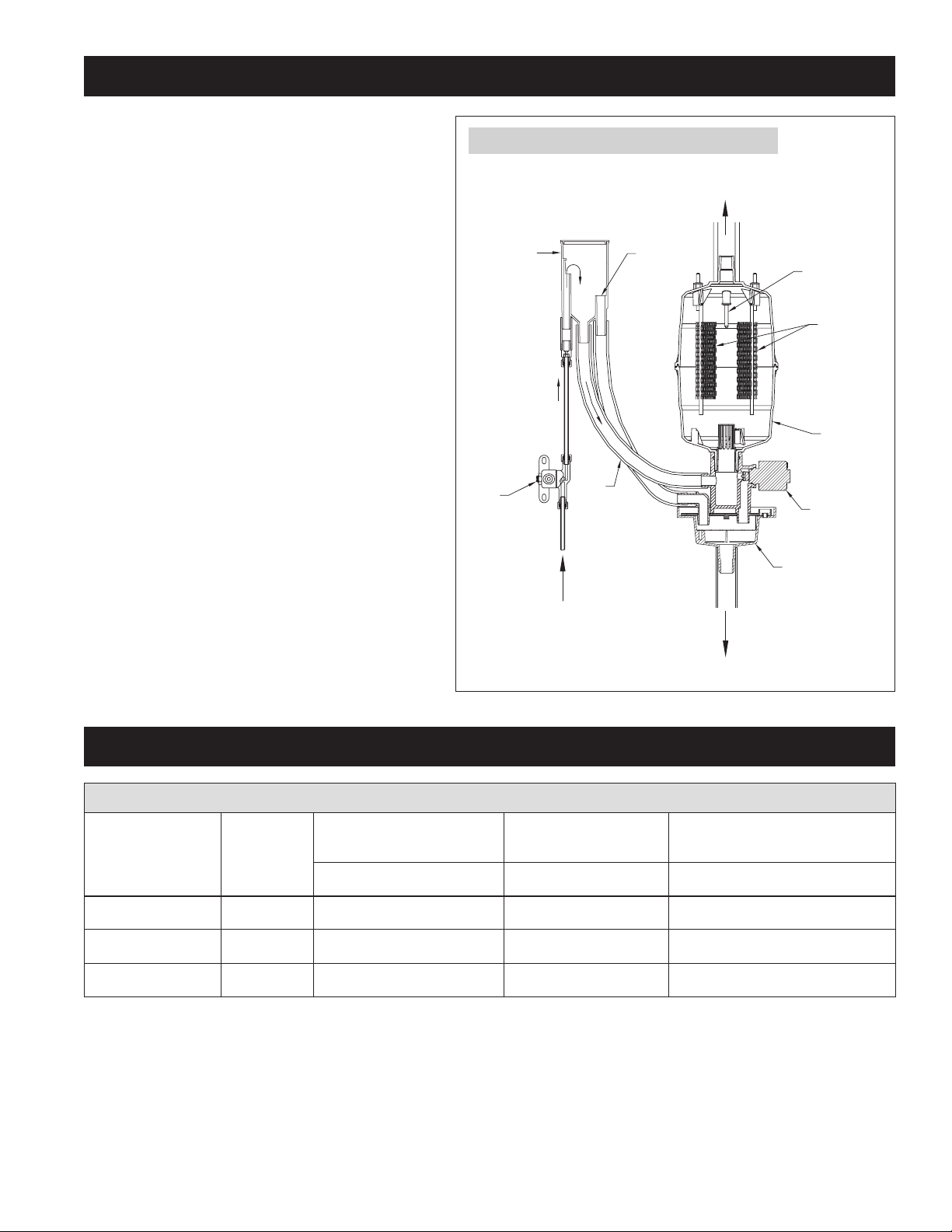
PRINCIPLES OF OPERATION
Steam
Outlet
Drain
Supply
Water
Drain Cup
Drain Valve
Canister
Electrodes
High Water
Level Sensor
Flow Control
Orifice
Inlet
Fill Valve
Overflow
Fill
Fill Cup
The Aprilaire
®
Model 800 Canister Steam Humidifier delivers
humidity in the form of steam to the conditioned space via
the HVAC system duct or optional Aprilaire Model 850 Fan
Pack. The humidifier generates steam by energizing two
electrodes that extend into a canister of water. Current
flowing between the electrodes causes the water to boil,
creating steam. Water is introduced to the humidifier through
a fill valve to a fill cup located in the top of the cabinet. The
fill cup serves as an overflow reservoir and provides an air
gap between the humidifier and water source. The steam
canister is filled from the bottom. The canister is seated
in a drain cup assembly which includes a drain valve. The
drain and fill valves work together to maintain water level
in the canister to deliver the rated steam capacity based
on the electrical conductivity of the water and to temper
drain water. See Figure 1 for representation of fill and drain
system and canister.
Steam is delivered into the airstream through a dispersion
tube mounted in the HVAC system ductwork. Openings in the
dispersion tube are fitted with “tubelets” which extend into
the center of the tube. The design of the dispersion tube and
tubelets distribute steam over a wide area in the duct and
direct any condensed moisture back into the steam hose.
FIGURE 1 – Fill and Drain System and Canister
SPECIFICATIONS & DIMENSIONS
TABLE 1 – Specifications
Voltage kW
Maximum
steam capacity
gal/day amps lbs
Nominal Current draw
(amps)
120V 1.4 11.5 11.5 23
208V 2.4 20.5 11.5 23
240V 2.8 23.3 11.5 23
90-1522
Humidifier unit
operating weight
3
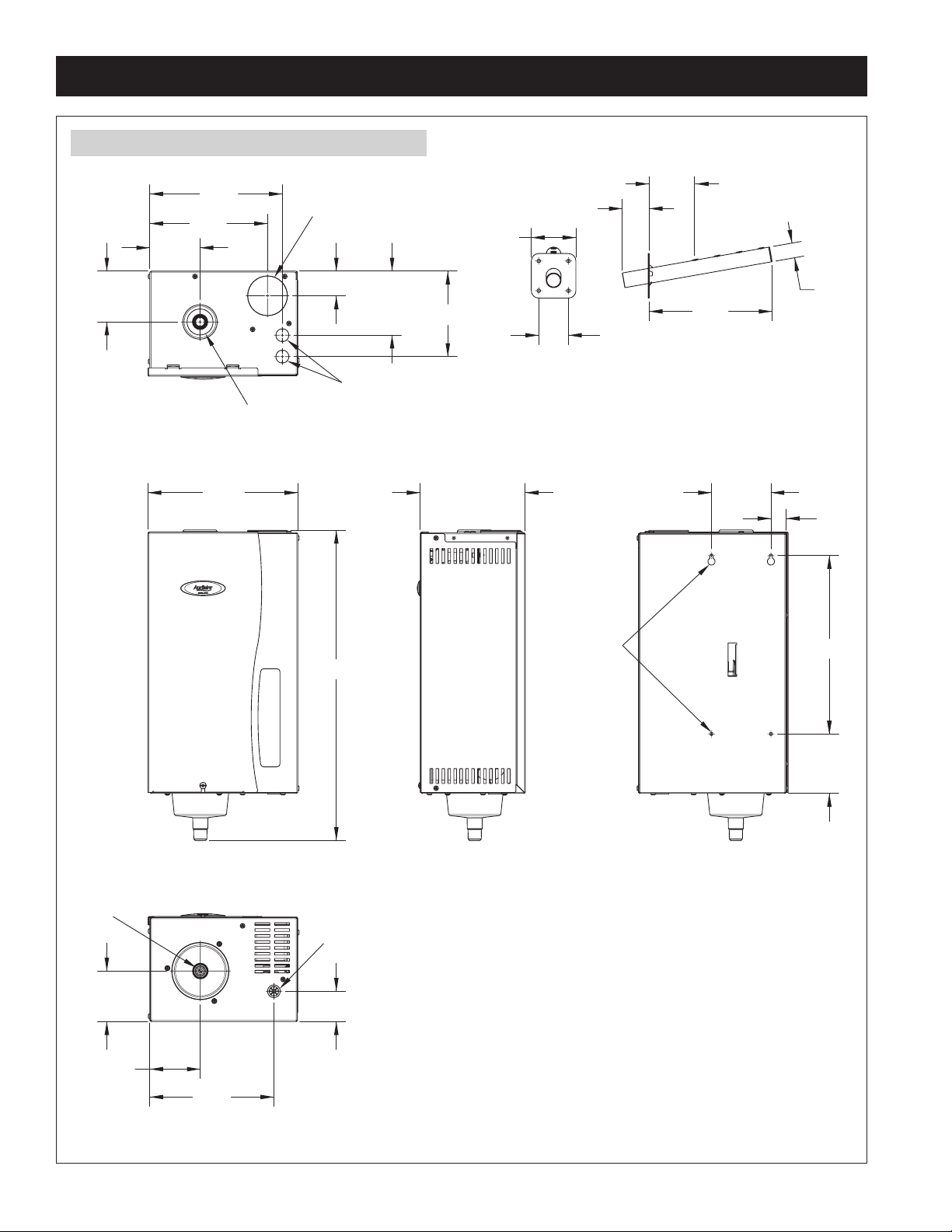
10 1/8"
20 7/8"
FRONT VIEW
3 3/8"
7 7/8"
8 7/8"
3 3/8"
1 5/8"
4 1/4"
5 3/4"
Dispersion Outlet
Electrical Knockouts
Fill Cup
TOP VIEW
7 1/8"
SIDE VIEW
1"
4"
4"
12"
BACK VIEW
Mounting
Holes
3 3/8"
8 3/8"
2"
3 3/8"
Water Fill Line Connection
Drain
BOTTOM VIEW
3" sq
2" sq
8 1/4"
1" dia
STEAM DISPERSION TUBE
3" Mounting Plate
to first opening
1 3/4"
SPECIFICATIONS & DIMENSIONS (CONTINUED)
FIGURE 2 – Humidifier & Dispersion Tube Dimensions
90-1518
4

INSTALLATION INSTRUCTIONS
CHOOSING A LOCATION
DISPERSION TUBE
When choosing a location for the dispersion tube three things must be considered: Location in duct, elevation with respect to the humidifier, and
distance from humidifier to dispersion tube.
Duct Location
The preferred location for the dispersion tube is in a supply duct because higher temperature air will more readily absorb the moisture. Whether
installed in a supply or return, the dispersion tube must be in a straight section of duct to avoid turbulent air and must be far enough upstream
of any obstruction or bends in the duct to allow the steam to be fully absorbed to prevent condensation. The exact distance from obstructions in
the duct depends on air temperature, RH set point, and airflow velocity in the duct. Table 2 provides absorption distance for typical conditions.
The higher the RH setting, the longer the absorption distance. Warmer air shortens the absorption distance. If absorption distance is a concern,
install dispersion tube in supply duct and configure humidifier and control to operate only during HVAC system heat call. Call Aprilaire Tech
Support at 1-800-334-6011 for additional information on absorption.
The dispersion tube must be mounted on a vertical surface with the tube angled up.
If the dispersion tube is mounted on insulated ductwork, make sure insulation is not more than 2” thick at tube location to prevent insulation
from blocking first steam outlet.
TABLE 2 – Absorption Distance (Minimum distance from dispersion tube downstream to any obstruction or bend in duct)
Input
Power
120 V 11.5 gal/day
208 V 20.5 gal/day
240 V 23.3 gal/day
Humidifier
Output
Airflow Velocity
300 fpm 7" 11" 13"
600 fpm 3" 6" 7"
1200 fpm 2" 3" 3"
1800 fpm < 2" 2" 2"
300 fpm 13" 19" 23"
600 fpm 6" 10" 12"
1200 fpm 3" 5" 6"
1800 fpm 2" 3" 4"
300 fpm 15" 23" 28"
600 fpm 6" 12" 13"
1200 fpm 5" 6" 7"
1800 fpm 3" 4" 5"
70°F & 30% RH
Setpoint
70°F & 45% RH
Setpoint
65°F & 45% RH
Setpoint
5
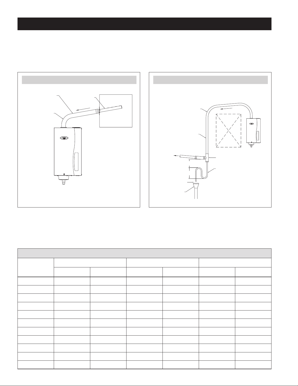
Pitch
Obstruction
90° long sweep
or two 45° elbows
6" min
8" min
Insulate hard pipe to
reduce steam loss
To
Dispersion
Tube
1" air gap
Open drain
required,
see note 1.
Drip tee installation for piping over obstruction,
or if dispersion tube is lower than humidifier.
NOTES:
1. Refer to governing codes for
drain pipe size and materials.
2. Support steam hose so there
are no sags or low spots.
Drip tee
Drain trap
90° long sweep
or two 45° elbows
Steam hose or pipe.
Insulate pipe with
1” fiberglass to
reduce steam loss.
Pitch*
Duct
Dispersion tube
*Pitch steam hose down from dispersion tube to humidifier:
2"/ft (15%) minimum when using steam hose.
1/4"/ft when using hard pipe.
INSTALLATION INSTRUCTIONS (CONTINUED)
Elevation
The preferred location for the dispersion tube is higher than the humidifier so that the steam hose has a constant downward slope of at least 2”
per foot from the dispersion tube to the humidifier. If hard pipe is used, the slope can be 1/4” per foot. With the constant downward slope, any
condensation that forms in the steam hose will drain back into the steam canister. See Figure 3. If the dispersion tube must be mounted below the
humidifier or if the steam hose needs to run up and over an obstruction, a drip tee with drain trap must be installed as shown in Figure 4.
FIGURE 3 – Dispersion Tube Mounted Above Humidifier
Distance from Humidifier to Dispersion Tube
90-1521
FIGURE 4 – Dispersion Tube Mounted Below Humidifier
90-1520
The capacity of the humidifier is reduced by the length of the steam hose or pipe due to condensation. The maximum recommended length
of steam hose is 6 feet. Use hard pipe insulated with 1” fiberglass for lengths greater than 6 feet. Table 3 provides humidifier capacity with
various lengths of steam hose and pipe. If 6-foot steam hose does not reach from humidifier to dispersion tube, splice in 1” copper pipe using
¾” x 1” reducing couplings as shown in Figure 5.
TABLE 3 – Steam Humidifier Capacity in Gallons/Day
Steam Hose
120 Volts 208 Volts 240 Volts
or Insulated
Pipe Length
< 2 ft. 11.5 11.5 20.5 20.5 23.3 23.3
2 ft. 11 11 20 20 23 23
4 ft. 10 11 19 20 22 23
Steam Hose Insulated Pipe Steam Hose Insulated Pipe Steam Hose Insulated Pipe
6 ft. 9 11 18 20 21 22
8 ft. 10 19 22
10 ft. 10 19 22
12 ft. 10 19 22
14 ft. 9 18 21
16 ft. 9 18 21
18 ft. 9 18 21
20 ft. 9 18 20
6
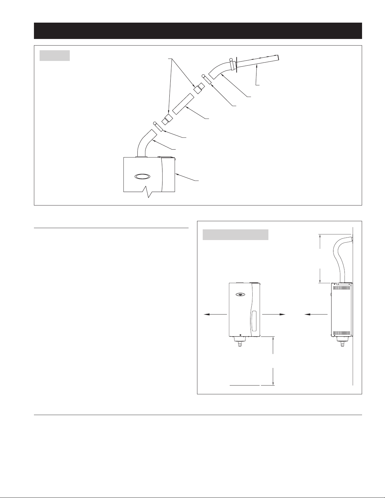
16" for
Steam
Hose
30" for
Service
Access
16" for
Electrical
Access
4"
16"
for Drain
FRONT VIEW
SIDE VIEW
INSTALLATION INSTRUCTIONS (CONTINUED)
Steam Hose
Dispersion Tube
Steam Hose
1-1/2" Hose Clamp
1-1/2" Hose Clamp
1" Copper Pipe
3/4" x 1" Reducing Coupling
Humidifier
FIGURE 5
90-1527
HUMIDIFIER
Do not mount humidifier in a location where ambient temperature
exceeds 120ºF or where freezing temperatures may occur.
Mount humidifier in a location that allows access for servicing, and
clearance to remove front panel for replacing the canister and side
panel for access to the electrical components during installation.
See Figure 6 for minimum clearances around humidifier.
The humidifier should be mounted as close to the dispersion
tube as possible. Table 3 shows how capacity is reduced as the
distance between the humidifier and dispersion tube increases. If
the humidifier is mounted on the duct directly below the dispersion
tube, allow space for a bend in the steam hose.
The humidifier can be mounted to a wood surface, or to sheet metal
ductwork if it is structurally stable. Do not mount humidifier to fiber
duct board.
The humidifier must be mounted to a vertical surface and must be
mounted level in the upright position.
Do not mount humidifier near sources of electromagnetic emissions
such as power distribution transformers.
ADHC (AUTOMATIC DIGITAL HUMIDIFIER CONTROL) MODEL 62
The ADHC must be mounted in the return air duct at least 6” upstream of any fresh air intake ducts or sources of moisture (steam dispersion
tube if it is in the return.) Follow instructions provided with the control.
If the application requires a wall-mounted control in the conditioned space, use Aprilaire Part #4993, which includes a wall-mountable manual
humidistat, a relay to activate the HVAC blower, and wiring instructions.
FIGURE 6 – Clearances
90-1519
7

INSTALLATION INSTRUCTIONS (CONTINUED)
PREPARE HUMIDIFIER FOR MOUNTING
Unpack carton. Open front panel by removing screw and lifting panel up and away from humidifier. Disconnect three wires from top of canister
by pulling straight up. The two large wires are the electrode conductors. The smaller wire is connected to the high water level sensor. Remove
canister by twisting and pulling it up and out of drain assembly. Remove two screws on right side of humidifier and lift side panel off housing to
expose electrical compartment.
INSTALL STEAM DISPERSION TUBE
Note: If humidifier will deliver steam via the Model 850 Fan Pack instead of the dispersion tube, follow instructions included with Fan Pack.
Make sure steam dispersion tube is mounted higher than the humidifier so that condensate that forms in the tube runs back into the canister.
If the dispersion tube cannot be mounted higher than the humidifier or if the steam hose must extend up from the humidifier then down to the
dispersion tube due to an obstruction, a drip tee and drain trap system must be installed as shown in Figure 4.
Drill a 1-1/4” diameter hole in a vertical surface of the duct at the location chosen for the dispersion tube. Position the tube so it is angled up.
Secure with four sheet metal screws provided.
MOUNT HUMIDIFIER
Secure humidifier to wood surface using screws provided, or to sheet metal duct. If mounting to stud frame wall, install two spanner boards to
studs and fasten humidifier to spanner boards. Make sure humidifier is mounted plumb.
Verify that the o-ring is in place in the slot in the drain assembly. Dampen the o-ring with water, then reinsert canister. (Do not use oil, grease or
any lubricant besides water.) Rotate the canister so the caution label is visible. Reattach the electrode conductors (interchangeable) and the high
water level sensor wire.
INSTALL STEAM HOSE
Six feet of steam hose is provided with the humidifier. If the steam hose must be cut, use a hacksaw. If additional length is required, use
1” O.D. metal or copper pipe. Do not use PVC pipe for steam line. Insulate pipe with 1” thick fiberglass to reduce steam loss. See Table 3 for
humidifier capacity at various lengths of steam hose and pipe.
Use the steam hose provided. Other hoses may have impurities which can cause foaming in the canister. Foaming can cause water level
inaccuracies and reduced steam production. When using pipe, remove all traces of residual materials used to connect the pipe to prevent foaming.
Attach steam hose to dispersion tube and then to top of canister using hose clamps provided. Make sure steam hose has a constant slope of
at least 2” per foot between the dispersion tube and the humidifier. Any and every low spot in the steam hose or pipe must have a drip tee and
drain trap. Fill drain trap with water before making final connections.
SUPPLY WATER
Plumb the humidifier to cold tap water. Do not use hot water because unheated supply water is used to cool water drained from the
humidifier. To operate properly, water conductivity must be within the range of 125 to 1,250 uS/cm (micro Siemens per centimeter), which is
roughly equivalent in hardness to 3 to 36 grains per gallon. Do not use demineralized water. The humidifier will produce steam immediately as
long as the mineral content of the water is within the specified range. For proper operation, supply water pressure must be between 25 psi and
120 psi.
Supply water piping must be free of oils, lubricants, solder flux and other contaminants, which can cause foaming in the canister that can lead to
water sputtering from the dispersion tube into the duct.
Install the saddle valve according to the instructions printed on the bag. Run ¼” copper tubing from the saddle valve to the humidifier. Extend the
tubing up through the port in the bottom of the humidifier and connect it to the fill valve. Double wrench to prevent leaking and damage to valve.
8

INSTALLATION INSTRUCTIONS (CONTINUED)
DRAIN LINE
Attach the 7/8” I.D. drain tubing provided to the drain assembly at the bottom of the humidifier. Secure with the hose clamp provided. Do not
over tighten.
Make sure the drain line has a constant downward slope from the humidifier to the drain and is not kinked or blocked.
AUTOMATIC DIGITAL CONTROL AND CONTROL WIRING
The control circuit operates on 24VAC.
The ADHC (Automatic Digital Humidifier Control) Model 62 must be mounted in the return air duct at least 6” upstream of any fresh air intake
ducts or sources of moisture (steam dispersion tube if it is in the return.) Follow instructions provided with the control. Connect “H” terminals on
ADHC to “HUMIDISTAT” terminals on humidifier circuit board.
If protection from over-humidification is desired, install optional high humidity limit switch #4594 at least 4 feet downstream of the dispersion
tube. If airflow verification is desired, install optional airflow proving switch #4592 in duct. The high humidity limit switch and the airflow proving
switch are wired in series with the ADHC (humidistat) circuit.
ELECTRICAL POWER WIRING & SHUT-OFF SWITCH
CAUTION
Only qualified electrical personnel should perform field wiring procedures. Improper wiring or contact with energized circuits
can cause property damage or severe personal injury.
All wiring must be installed in accordance with all governing electrical codes and with the wiring diagram provided inside the front panel.
Power wiring must be rated for 105°C (220°F).
Do not loop power wiring.
Do not use aluminum wire.
A safety grounding system that meets all governing electrical codes is required. The ground connection must be made with solid metal to metal
connections. Ground wire must be the same size as the power wiring.
Humidifier draws 11.5 amps ±10%. Use12.7 amps when sizing circuit.
The Model 800 Steam Humidifier can operate with 120, 208 or 240 VAC. If using 208V or 240V, remove jumper between N and L2
terminals on power terminal block.
When wiring to 208 or 240 V, run two conductors plus neutral plus ground.
WIRING INSTRUCTIONS
Install disconnect switch (not provided) between line power source and humidifier.
Knock-outs for power wiring and low voltage control circuit wiring are located on the top of the humidifier.
Connect power and ground wiring as shown in wiring diagram, Figure 7.
Do not run high voltage power lines over internal circuit boards.
9
(PROVIDED)
(NOT PROVIDED)
MAIN POWER SWITCH
J10-1
AUTOMATIC DIGITAL
J1-1
J1-2
ELECTRODE
WATER LEVEL
ELECTRODE
24V AC
COM
ORG
YEL/WHT
J5
J2
RED
RED
BLK
BLK
YEL
YEL
BRN
BRN
BLU
WHT
WHT
COM
24V AC
COM
24V AC
COM
24V AC
DRAIN VALV E
FILL VA LVE
POWER RELAY COIL
J3
J4
J6-2
J6-1
J8
J7
120V AC
SAFETY SWITCH
BLU
+24V DC
+24V DC
J13-2
J13-1
J11-2
J11-1
J12-2
J12-1
STEAM CYLINDER
J3-2
J3-1
J1-2
01
L1
N
L2
TERMINAL
BLOCK
BLK
BLK
BLK
68
42
WHT
24V AC
YELLYEL/WHT
CONTROL PCB CURRENT SENSING PCB
J1-1
TRANSFORMER
75VA
HUMIDITY CONTROL
HIGH LEVEL PROBE
STATIC
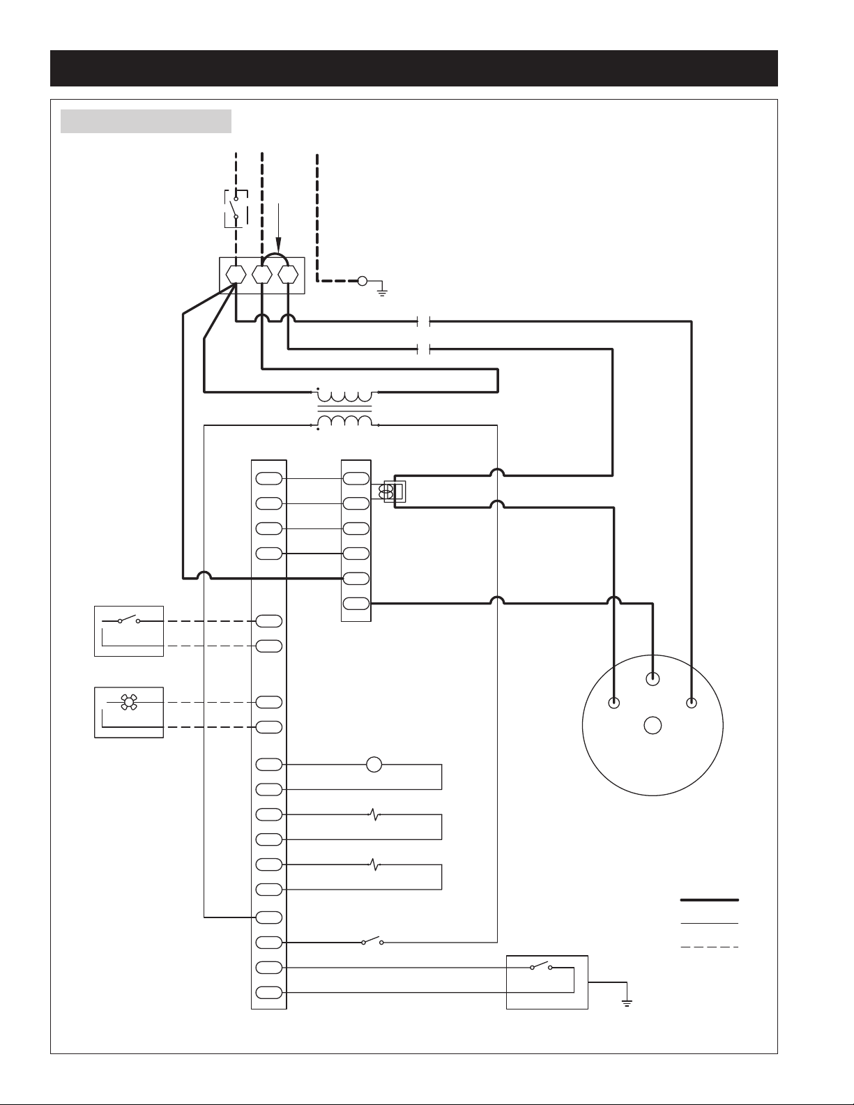
CONTROL CIRCUIT WIRING
HIGH VOLTAGE WIRING
FIELD WIRING
(OPTIONAL)
FAN PA CK
+24V AC
COM
HUMIDISTATFAN
BLK
YEL
FOR 120V INSTALLATION,
CONNECT POWER TO L1 AND N
WITH N-L2 JUMPER IN PLACE
(PROVIDED).
FOR 208 OR 240 VOLT
INSTALLATIONS,
REMOVE N-L2 JUMPER
,
AND CONNECT POWER TO L1, N, AND L2
YEL
POWER RELAY CONTACTS
PROBE
J4
J2
DISCHARGE
GROUND
JUMPER
J10-2
DISPLAY PA NEL
RIBBON CABLE
GROUND
INSTALLATION INSTRUCTIONS (CONTINUED)
FIGURE 7 – Wiring Diagram
90-1515
10
 Loading...